

Page 1

UUsseerr MMaannuuaall
WL630PCI Wireless B/G
PCI Card
User Manual
Version 1.1
CONTENTS
1 INTRODUCTION TO WL630PCI WIRELESS B/G PCI CARD................................................... 3
1.1 P
ACKAGE CONTENTS.................................................................................................................... 3
1.2 FEATURES .....................................................................................................................................3
1.3 LED INDICATORS..........................................................................................................................4
2 INSTALLATION .................................................................................................................................5
YSTEM REQUIREMENTS.............................................................................................................. 5
2.1 S
2.2 STEP 1: INSTALL THE DRIVER & UTILITY......................................................................................5
TEP 2: INSTALL THE DEVICE.......................................................................................................8
2.3 S
2.4 VERIFY INSTALLATION.................................................................................................................10
2.5 UNINSTALLATION......................................................................................................................... 10
3 NETWORK CONNECTION ............................................................................................................11
N WINDOWS 98SE/ME.............................................................................................................. 11
3.1 I
N WINDOWS 2000/XP ...............................................................................................................13
3.2 I
4 IP ADDRESS ....................................................................................................................................14
5 CONFIGURATION UTILITY........................................................................................................... 15
5.1 M
AIN TAB ....................................................................................................................................16
5.2 PROFILE MANAGER TAB .............................................................................................................21
NFORMATION TAB ......................................................................................................................22
5.3 I
6 EXAMPLE OF CONNECTION TO AN ACCESS POINT...........................................................23
Product warranty does not apply to damage caused by lightning, power surges or wrong voltage usage.
PPaaggee 11 ooff 2244
Page 2

UUsseerr MMaannuuaall
Declaration of Conformity
FCC Certification
The United States Federal Communication Commission (FCC) and the Canadian Department
of Communications have established certain rules governing the use of electronic equipment.
Part15, Class B
This device complies with Part 15 of FCC rules. Operation is subject to the following two
conditions:
1) This device may not cause harmful interface, and
2) This device must accept any interface received, including interface that may cause
undesired operation. This equipment has been tested and found to comply with the limits for a
Class B digital device, pursuant to Part 15 of the FCC Rules. These limits are designed to
provide reasonable protection against harmful interference in a residential installation. This
equipment generates, uses and can radiate radio frequency energy, and if not installed and
used in accordance with the instructions, may cause harmful interference to radio
communications. However, there is no guarantee that interference will not occur in a
particular installation. If this equipment does cause harmful interference to radio or television
reception, which can be determined by turning off and on, the user is encouraged to try to
correct the interference by one or more of the following measures:
• Reorient or relocate the receiving antenna.
• Increase the distance between the equipment and receiver.
• Connect the equipment into an outlet on a circuit different from that to which the receiver
is connected.
CAUTION:
1. To comply with FCC RF exposure compliance requirements, a separation distance of at
least 20 cm must be maintained between the antenna of this device and all persons.
2. This transmitter must not be co-located or operating in conjunction with any other antenna
or transmitter.
PPaaggee 22 ooff 2244
Page 3
UUsseerr MMaannuuaall
1 Introduction to WL630PCI Wireless B/G PCI Card
The WL630PCI Wireless B/G PCI Card is designed for creating a wireless workstation for
desktop computer. The WL630PCI Wireless B/G PCI Card is compliant with both Wireless-G
(802.11g) and Wireless-B (802.11b).
WL630PCI is based on Texas Instruments’ (TI) G++ Turbo mode (125Mbps equivalent)
performance enhancing technology. The PCI card connects to wireless network at incredible
speeds and delivers blazing fast data rates up to 125 Mbps*. An example of 125Mbps*
Wireless LAN set up will be Aztech WL630PCI (TI chipset) + DSL600EW (TI chipset).
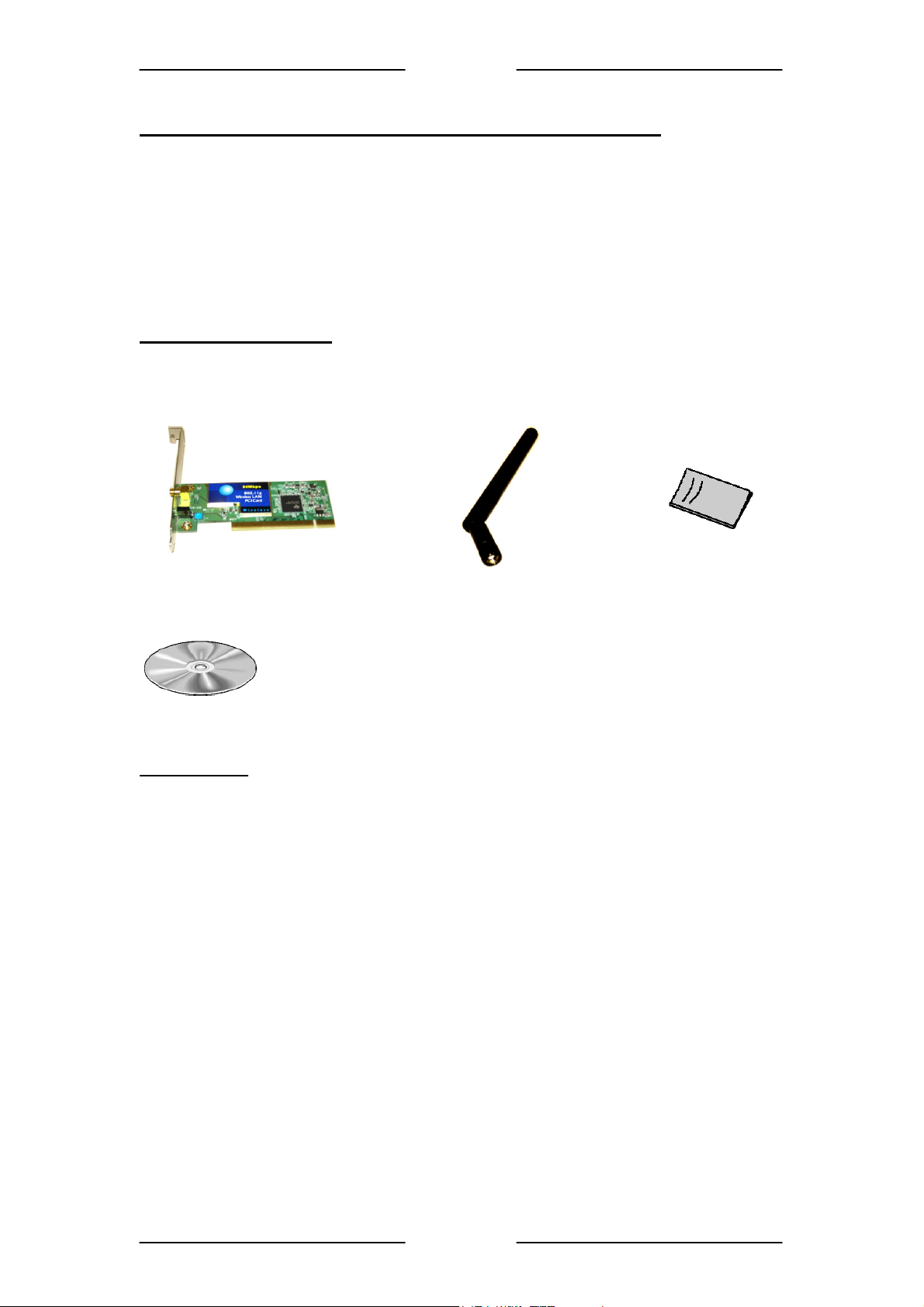
1.1 Package Contents
Make sure that you have the following items. If any of the items is damaged or missing,
please contact your dealer immediately.
WL630PCI Wireless B/G PCI Card (Qty:1) Antenna (Qty:1) Easy Start (Qty:1)
Installation CD (Qty:1)
1.2 Features
• Complies with IEEE 802.11b standard and draft standard 802.11g for 2.4GHz Wireless
LAN
• Works with all existing network infrastructure
• Complies with specific wireless products and services
• Capable of up to 256-Bit WEP Encryption
• Freedom to roam while staying connected
• 22-Mbps Packet Binary Convolution Coding (PBCC) (according to the IEEE Standard
802.11b high-rate specification)
• Up to 125Mbps
• Complies with Windows 98SE/2000/ME/XP
• Lower power consumption
• Easy to install and configure
∗
Applicable to Texas Instruments end-to-end chipsets Wireless LAN solution on Windows®
(
2000/XP platform. Maximum wireless signal rate derived from IEEE Standard 802.11g
specifications and does not represent actual data throughput. Network conditions and
environmental factors, including volume of network traffic, building materials and construction,
and network overhead, lower actual data throughput rate)
∗
data rate
PPaaggee 33 ooff 2244
Page 4

UUsseerr MMaannuuaall
1.3 LED Indicators
Power Indicator (Green LED):
The LED will light up when the device is connected to a network (an AP or Peer-to-Peer).
The LED will blink when the device is scanning for all available networks.
Act Indicator (Green LED):
The LED will flicker when there is transmitting/receiving of wireless data.
PPaaggee 44 ooff 2244
Page 5
UUsseerr MMaannuuaall
2 Installation
2.1 System Requirements
• Desktop PC
• Pentium® 233 processor or higher
• 128MB RAM
• A free PCI-Bus slot
• 20MB hard disk space (system files and modem driver only)
• CD-ROM drive
• Windows® 98 SE / Windows® Me / Windows® XP / Windows® 2000
2.2 Step 1: Install the Driver & Utility
Make sure you run the setup utility first before plugging in the PCI Card into your PC. If your
PCI Card is plugged into your PC first, the network controller will be prompted. Click Cancel.
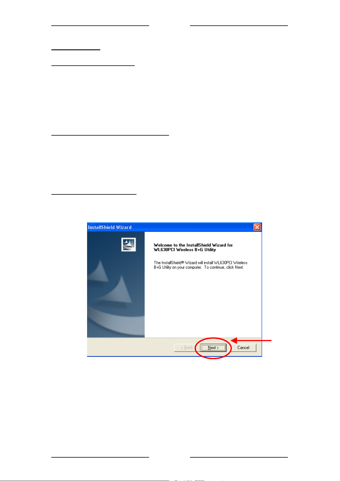
Exit all Windows programs. Insert the Installation CD into your CD-ROM. The CD will run
automatically. If the Installation CD auto run fails, please run the “Setup.exe” file in the CD.
For Windows 98SE/ME/2000/XP
1. When the Welcome screen appears, click “Next” to continue.
Click Here
PPaaggee 55 ooff 2244
Page 6
UUsseerr MMaannuuaall
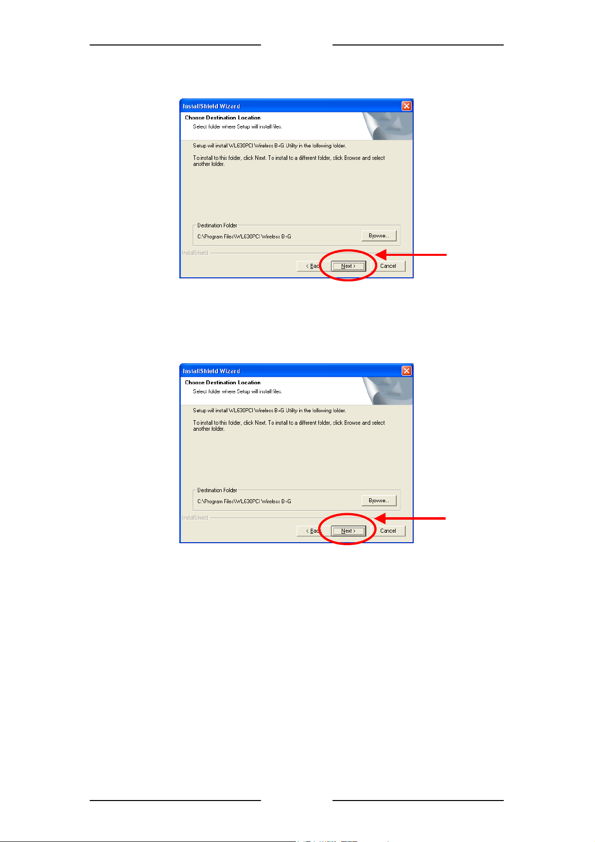
2. The below screen will be shown. Click “Next” to continue.
Click Here
3. The below screen will be shown. Click “Next” to continue and the installation program
will start running automatically.
PPaaggee 66 ooff 2244
Click Here
Page 7
UUsseerr MMaannuuaall
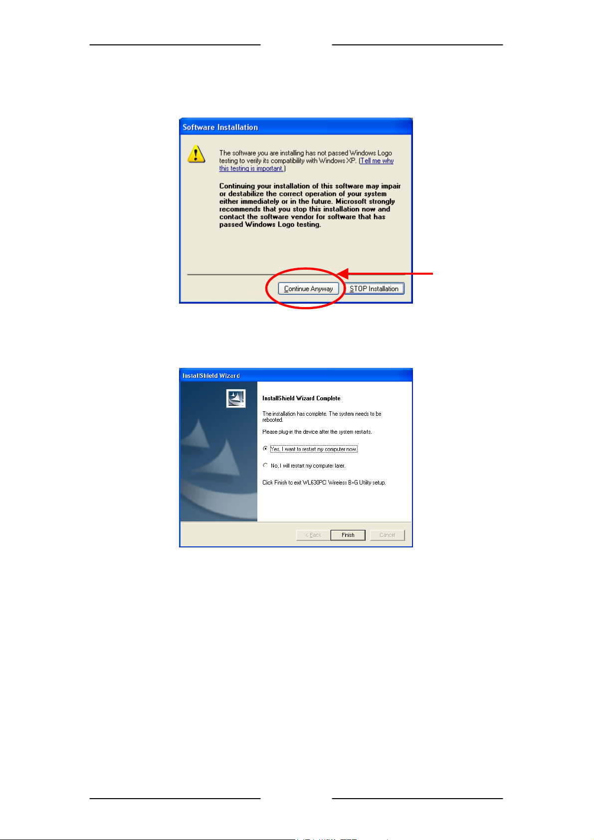
4. For Windows 2000 and Windows XP, you may be prompted for Digital Signature not
found. Just click “Yes” or “Continue Anyway” to continue with the installation.
Click Here
5
. When the below screen is shown, click “Finish” to restart the system.
PPaaggee 77 ooff 2244
Page 8
UUsseerr MMaannuuaall
2.3 Step 2: Install the Device
Note: Before you install the device to your computer, make sure you have
installed the driver and utility as described in the previous section.
Shut down the PC and remove the power cord from the PC. Locate your PCI slot and then
insert the Wireless B/G PCI Card into the slot
For Windows 98SE/ME
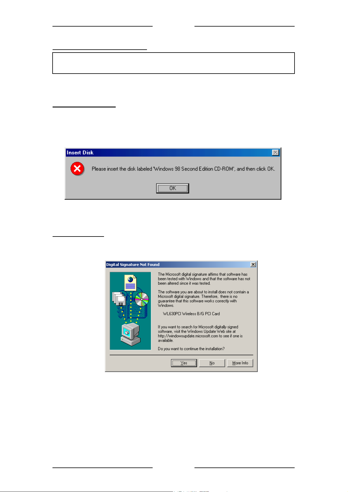
4. Before installing the device, make sure you have your original Windows 98 CD-ROM on
hand (not required for Windows ME). When the prompt for “Windows 98 Second Edition
CD-ROM” window appears, insert the CD-ROM as requested. Click “OK” to continue the
installation.
5. The installation will continue and the system may prompt for a “Version Conflict”. Click
“Yes” to keep the existing file. This completes the installation of the device.
For Windows 2000
4. When the “Digital Signature Not Found” screen appears, click “Yes” to continue the
installation.
5. This completes the installation of the device.
PPaaggee 88 ooff 2244
Page 9

UUsseerr MMaannuuaall
For Windows XP
4. Windows may ask to connect to Windows Update to search for software. Select “No”.
When below is prompted, click “Next” to continue the installation.
Click Here
5. When the “Hardware Installation” screen appears, click “Continue Anyway” to continue
the installation.
Click Here
6. When the following screen appears, click “Finish” to complete the installation of the
device.
Click Here
PPaaggee 99 ooff 2244
Page 10

UUsseerr MMaannuuaall
2.4 Verify Installation
o verify if the device exists in your computer and works, go to Start Æ Settings Æ Control
T
Panel Æ System Æ Hardware Æ Device Manager. Expand the Network Adapters
category. If the WL630PCI Wireless B/G PCI Card is listed here, it means that your device is
properly installed and enabled.
.5 Uninstallation
2
1. To uninstall the drive
2
. Open the Add/Remove Programs.
3. Select the WL630PCI Wireless B/G Utility in the Add/Remove Program
then click on the Remove.
4. Follow the on screen instructions to uninstall the driver and utility. After the uninsta
shut down and plug out the w
r and utility, go to the Control Panel of your system.
s and
ireless PCI card.
llation,
PPaaggee 1100 ooff 2244
Page 11

UUsseerr MMaannuuaall
3 NETWORK CONNECTION
Once the device driver is well installed, a network setting described in the following should be
also established.
3.1 In Windows 98SE/ME
1. Go to Start Æ Settings Æ Control Panel Æ Network.
Make sure that all the required components are installed. If any components are missing,
click on the “Add” button to add them in.
2. For making your computer visible on the network, enable the “File and Print Sharing…”
and check on the boxes as shown.
PPaaggee 1111 ooff 2244
Page 12

UUsseerr MMaannuuaall
3. Click the “Identification” tab. Make up a name that is unique from the other computers'
names on the network. Type the name of your workgroup, which should be the same
used by all of the other PCs on the network.
4. Click the “Access Control” tab. Make sure that “Share-level access control” is selected.
If connecting to a Netware server, share level can be set to “User-level access control”.
5. When finished, restart your computer to activate the new device.
PPaaggee 1122 ooff 2244
Page 13

UUsseerr MMaannuuaall
3.2 In Windows 2000/XP
1. For Windows 2000, go to Start Æ Settings Æ Control Panel Æ Network and Dial-up
Connections Æ Local Area Connection Æ Properties.
For Windows XP, go to Start Æ Control Panel Æ Network and Internet Connections
Æ Network Connection Æ Wireless Network Connection Enabled WL630PCI
Wireless B/G PCI Card.
2. Make sure that all the required components are installed. If any components are missing,
click on the “Install…” button to add them in.
PPaaggee 1133 ooff 2244
Page 14

UUsseerr MMaannuuaall
4 IP Address
1. To configure a dynamic IP address check the “Obtain an IP Address Automatically”
option.
2. To configure a fixed IP, check the “Use the following IP address” option. Then enter an
IP address into the empty field. For example, enter 192.168.1.1 in the IP address field and
255.255.255.0 for the Subnet Mask.
Note: When assigning IP Addresses to the computers on the network, remember to
have the IP address for each computer set on the same subnet mask.
PPaaggee 1144 ooff 2244
Page 15

UUsseerr MMaannuuaall
5 Configuration Utility
After the Wireless PCI Card has been successfully installed, users can use the included
Configuration Utility to set their preference.
To activate the Configuration Utility, you may go to Start J Program J WL630PCI Wireless
B+G J WL630PCI Wireless B+G Utility.
There is also a Configuration Utility icon created on the desktop. You can also open the
Configuration Utility by clicking the icon.
A
fter you have activated the Configuration Utility icon on the desktop, there will be also a
Configuration Utility icon appeared in the taskbar (as in the red circle). You can open the
Configuration Utility by clicking on the icon.
PPaaggee 1155 ooff 2244
Page 16

UUsseerr MMaannuuaall
5.1 Main Tab
Open up the Configuration Utility and the below screen will display the current status of the
WL630PCI Wireless PCI Card.
Item Description
Configure
using Windows
Zero Config.
Profile name
SSID
BBS ID
Current Tx
Rate
Channel
BSS type
External Configuration Checkbox (Windows XP only): A checkbox that
enables you to disable the WLAN Station Configuration Utility and
indicates that the station driver is to be configured with Windows XP’s
built-in Windows Zero Configuration Utility (WZC).
On Windows XP systems, the WZC service is automatically stopped when
the WLAN Configuration Utility is installed. The WZC is started when
you check the Configure using Windows Zero Configuration
checkbox.
The checkbox is only displayed on Windows XP systems.
To disable the WZC and access using the Configuration Utility, rightclick on the WLAN Utility and then uncheck the Configure using WZC.
The profile name that is currently connected.
The SSID is the unique name shared among all points in your wireless
network.
The name must be identical for all devices and points attempting to
connect to the same network.
Indicates that the network does not require special security settings
and access rights in order to connect to it (that is, you can connect to the
network by setting the station’s privacy mode to None and authentication
mode to None).
Indicates that the network requires special security settings and access
rights in order to connect to it.
Indicates a hidden network that is not broadcasting its SSID. The SSID
for such networks are listed as <Hidden Network>. In order to connect to
such a network, you must know the network’s SSID.
The MAC address for the Access Point or station.
It displays the currently connected rate.
The channel that is currently connected.
The type of connection, either Access Point or Peer-to-Peer.
PPaaggee 1166 ooff 2244
Page 17

UUsseerr MMaannuuaall
y
y
Item Description
Tx Rate /Rx
Rate
Signal quality
Connect
The actual instantaneous transmit and receive rates, in Mbps.
The signal strength from the network Access Point or station. The
strength is displayed in three formats: a signal quality level (one of five
levels, from Bad to Best), a numerical value in dBm, and a signal quality
bar graph with a scale of –82 to –10.
Highlight one of the devices from the list area and then press the
Connect button to access it.
Profile Name: Enter the profile name you wish to have.
Set Configuration: The Set Configuration area contains the following
fields
SSID Name: The SSID for the current profile
BSS Type: The BSS type, either peer-to-peer or Access Point
Channel: The preferred channel on which to make a connection
(available for peer-to-peer connections only)
Band: The band on which to make a connection.
Super Profile:Determines the security settings available to you, and can
be one of the following:
Personal: Enables only the basic security settings that you are likely to
need at home.
Enterprise: Enables all security settings, including more complex
certificate-based settings that you may need in an office.
Security: Determines the type of security to use for this connection, and
can be one of the following:
None
WEP
WPA2
Any WPA
WEP: Wired Equivalent Privacy (WEP) is a data security mechanism
based on a 64 Bit/128 Bit/256 Bit shared key algorithm.
Press the Configure button to change WEP configuration.
Note: You must use the same Default Ke
Encr
establish a connection.
KEY1 ~ KEY 4: You can specify up to 4 different keys, but only one can
be used at a time.
Encryption: Enter the key value in this field.
ption Key on both the host and destination devices in order to
#, Key Size, and
PPaaggee 1177 ooff 2244
Page 18

UUsseerr MMaannuuaall
A
Item Description
Select Hexadecimal (Hex) if you are using hexadecimal numbers (0-9, or
A-F).
Select ASCII if you are using ASCII characters (case-sensitive).
characters are: 0,1,2,...8,9 and a,b,c,d,...x,y,z.
10 Hexadecimal digits or 5 ASCII characters are needed if 64-bit WEP is
used;
26 Hexadecimal digits or 13 ASCII characters are needed if 128-bit WEP
is used;
58 Hexadecimal digits or 29 ASCII characters are needed if 256-bit WEP
is used.
For example, the characters “1122aabbcc” are in 10 Hexadecimal digits.
For example, the characters “test1” are 5 ASCII keys.
WPA2 & Any WPA: (WiFi Protected Access)is more secure than WEP,
and should be used if possible.
Authentication Mode: Determines the type of authentication to use for this
connection.
With Super Profile set to Personal, this field can be one of the following:
Open: If your access point/wireless router is using "Open" authentication,
then the wireless adapter will need to be set to the same authentication
type.
Shared Key: Shared Key is when both the sender and the recipient share
a secret key.
Auto Switch: Select Auto Switch for the adapter to automatically select
the appropriate
PSK: In the Passphrase field, enter the key that you are sharing with the
network for the WLAN connection. By default, the key that you type is
masked with asterisks (*). To view the key that you entered, check
Unmask.
With Super Profile set to Enterprise, this field can also be one of the
following:
TLS
PEAP – MS-CHAP-V2 (only with CCX mode enabled)
PEAP – GTC (only with CCX mode enabled)
LEAP (only with CCX mode enabled)
The Personal Certificate window enables you to supply a personal
certificate for use with TLS and PEAP – MS-CHAP-V2 authentication.
This window is only applicable with Enterprise security.
Personal Certificate:
SCII
PPaaggee 1188 ooff 2244
Page 19

UUsseerr MMaannuuaall
Item Description
To supply a Personal Certificate:
In the User Name field, type in the user name assigned to the certificate.
Select a certificate by clicking Browse. The standard Windows Select
Certificate window is displayed:
Select a certificate from the list, and click OK. The name of the certificate
is displayed in the textbox in the middle of the Personal Certificate
window.
To view the certificate, click View. The certificate is displayed:
The Password window enables you to supply a login name and password
for use when selecting LEAP or PEAP – GTC authentication.
To specify a user name and password:
1.Select the appropriate radio button to indicate whether:
PPaaggee 1199 ooff 2244
Page 20

UUsseerr MMaannuuaall
Item Description
You are supplying a user name and password now.
The utility prompts you for them each time you try to connect to a network.
2. To provide a user name and password now, enter them in the fields
provided.
Not all values for Authentication Mode are available for all Security
settings.
Enable CCX mode: Enables connections in CCX mode. When checked,
additional authentication modes are available.
This checkbox is only enabled when Super Profile is set to Enterprise.
Configure: Click Configure to open the configuration window.
Open Advanced Mode: Click Open Advanced Mode to configure the
following screen:
Power Save Mode: Indicates whether to use power saving. This field can
be one of the following:
None: No power save mode.
Max: Max power save mode.
TX Power Level: The transmit power level, which can be one of the
following:
Low Power (6% of full power)
Medium-Low Power (12%)
Medium-Power (25%)
Medium-High Power (50%)
High Power (100%)
TX Rate: The preferred rate of transmission, in Mbps. The options for this
field are based on the selected band and channel,
Packet Burst: Indicates whether the Packet Bursting feature is enabled.
Turbo Mode: Indicates whether the 4X feature is enabled.
Fragment Threshold: The maximum fragment length, in bytes. The value
is an even number from 256 to 4096 (default is 4096).
RTS Threshold: The minimum packet length for sending an RTS frame,
in bytes. The value must be greater than 0 (default is 4096).
Preamble: Either short or long
Retry limits: The number of retries to attempt, if necessary, when
sending a frame. There are two Retry limits fields:
Short: For frames without an RTS frame
Long: For frames with an RTS frame
To hide the advanced fields, click Close Advanced Mode.
OK: When the configuration is done, click OK to save.
Cancel: Click Cancel to discard changes.
Rescan
Configure Click Configure to modify the settings for the profiles with the SSID of the
Searches for all available networks. Clicking on the button, the device will
start to rescan and list all available sites.
selected network.
If no profile exists, the Profile Configuration window is displayed so that
you can create a profile. The Profile Name field is blank.
If profile exists, the Profile Configuration window is displayed so that
you can modify its settings.
PPaaggee 2200 ooff 2244
Page 21

UUsseerr MMaannuuaall
5.2 Profile Manager Tab
The Profile Manager enables you to create, modify and delete the profiles that the station
uses to connect to WLAN networks, to activate and de-activate profiles, and to raise and
lower a profile’s priority.
ll profiles are displayed in one of the following lists:
A
Profiles Pool: A list of inactive profiles, that is, profiles that
making a connection.
Active Profiles: A lis
connection.
Item Description
New Click New to create a new profile.
Edit Click Edit to edit an exiting profile.
D elete Click Delete to delete the profile that is currently selected in the Profile
OK Click OK to save any changes to profiles and connection settings, and
Cancel Click Cancel to discard any changes to profiles and connection settings,
Apply Click Apply to save any changes to profiles and connection settings.
t of active profiles, that is, profiles that can be used for making a
The new profile is inactive and is added to the Profiles Pool list.
Manager tab. The following confirmation dialog box is displayed:
then minimizes the utility to the Windows system tray.
and then minimizes the utility to the Windows system tray.
cannot currently be used for
PPaaggee 2211 ooff 2244
Page 22

UUsseerr MMaannuuaall
A
5.3 Information Tab
The Information tab displays information maintained by the driver, such as the number of
packet errors and the total number of bytes received or transmitted. The tab also displays
information about the current connection, as well as network information about the station.
The statistics are for the period starting when you last connected to a network. The statistics
are refreshed at least twice a second.
Connection
Status
Duration
Receive /
Transmit
Statistics
Connection
Information
Network
Information
Item Description
Indicates whether the station is currently connected to a network. This is
the same connection status as displayed on the Main tab.
The time since the station last connected to a network.
ll information is for the period starting when you last connected to a
network, except for Beacons, which is for the period starting when you
installed the driver.
Information about association and authentication attempts with the
currently selected network, as well as some connection settings.
Network information, such as the IP address, of the station.
PPaaggee 2222 ooff 2244
Page 23

UUsseerr MMaannuuaall
6 Example of connection to an Access Point
1. At the Main tab, highlight one of the devices from the list area that you wish to connect and
then press the Connect button to access it.
2. The Profile Configuration window will be displayed so that you can create a profile.
3. The SSID name will appear on the Profile Name. You can change the Profile Name if you
wish to.
4. Select Personal for Super Profile and select Open for the Authentication Mode.
5. Select None for the Security if the network does not require special security settings and
access rights in order to connect to it. Please proceed to Step 11 on Page 20.
6. Select WEP for the Security if the network requires special security settings and
access rights in order to connect to it. Then, click on Configure… to set the WEP
Configuration.
PPaaggee 2233 ooff 2244
Page 24

UUsseerr MMaannuuaall
7. The WEP Configuration screen will be shown.
8. Select Hexadecimal (Hex) if you are using hexadecimal numbers (0-9, or A-F).
10 Hexadecimal digits are needed if 64-bit WEP is used;
26 Hexadecimal digits are needed if 128-bit WEP is used;
58 Hexadecimal digits are needed if 256-bit WEP is used.
For example, the characters “1122aabbcc” are in 10 Hexadecimal digits.
9. Select ASCII if you are using ASCII characters (case-sensitive). ASCII characters are:
0,1,2,...8,9 and a,b,c,d,...x,y,z.
5 ASCII characters are needed if 64-bit WEP is used;
13 ASCII characters are needed if 128-bit WEP is used;
29 ASCII characters are needed if 256-bit WEP is used.
For example, the characters “test1” are 5 ASCII keys.
10. Click OK to exit the WEP Configuration.
11. Click OK to exit the Profile Configuration and then click on Apply in the Main tab to
activate the settings.
PPaaggee 2244 ooff 2244
 Loading...