

Page 1

VDSL5040GRV(AC)
1200Mbps VDSL2 Wireless-AC
4-Port Gateway
Page 2

User Manual
© Copyright 2014 All rights reserved.
No part of this document may be reproduced, republished, or retransmitted in any form or
by any means whatsoever, whether electronically or mechanically, including, but not limited
to, by way of photocopying, recording, information recording, or through retrieval systems
without the express written permission. We reserve the right to revise this document at any
time without the obligation to notify any person and/or entity. All other company or product
names mentioned are used for identification purposes only and may be trademarks of their
respective owners.
LIMITATION OF LIABILITY AND DAMAGES
THE PRODUCT AND THE SOFTWARES WITHIN ARE PROVIDED "AS IS," BASIS. THE MANUFACTURER
AND MANUFACTURER’S RESELLERS (COLLECTIVELY REFERRED TO AS “THE SELLERS”) DISCLAIM
ALL WARRANTIES, EXPRESS, IMPLIED OR STATUTORY, INCLUDING WITHOUT LIMITATION THE
IMPLIED WARRANTIES OF NON-INFRINGEMENT, MERCHANTABILITY OR FITNESS FOR A
PARTICULAR PURPOSE, OR ANY WARRANTIES ARISING FROM COURSE OF DEALING, COURSE
OF PERFORMANCE, OR USAGE OF TRADE. IN NO EVENT WILL THE SELLERS BE LIABLE FOR
DAMAGES OR LOSS, INCLUDING BUT NOT LIMITED TO DIRECT, INDIRECT, SPECIAL WILLFUL,
PUNITIVE, INCIDENTAL, EXEMPLARY, OR CONSEQUENTIAL, DAMAGES, DAMAGES FOR LOSS OF
BUSINESS PROFITS, OR DAMAGES FOR LOSS OF BUSINESS OF ANY CUSTOMER OR ANY THIRD
PARTY ARISING OUT OF THE USE OR THE INABILITY TO USE THE PRODUCT OR THE SOFTWARES,
INCLUDING BUT NOT LIMITED TO THOSE RESULTING FROM DEFECTS IN THE PRODUCT OR
SOFTWARE OR DOCUMENTATION, OR LOSS OR INACCURACY OF DATA OF ANY KIND,
WHETHER BASED ON CONTRACT, TORT OR ANY OTHER LEGAL THEORY, EVEN IF THE PARTIES
HAVE BEEN ADVISED OF THE POSSIBILITY OF SUCH DAMAGES. THE ENTIRE RISK AS TO THE
RESULTS AND PERFORMANCE OF THE PRODUCT OR ITS SOFTWARE IS ASSUMED BY CUSTOMER.
BECAUSE SOME STATES DO NOT ALLOW THE EXCLUSION OR LIMITATION OF LIABLITY FOR
DAMAGES, THE ABOVE LIMITATION MAY NOT APPLY TO THE PARTIES. IN NO EVENT WILL THE
SELLERS’ TOTAL CUMULATIVE LIABILITY OF EACH AND EVERY KIND IN RELATION TO THE
PRODUCT OR ITS SOFTWARE EXCEED THE AMOUNT PAID BY CUSTOMER FOR THE PRODUCT.
Page 2 of 44
Page 3

User Manual
Contents
About the Device ........................................................................................................ 5
Requirements ................................................................................................ 6
Package Contents ....................................................................................... 6
Device Design ............................................................................................... 7
Front Panel ..................................................................................................... 7
Getting Started ........................................................................................................... 10
Planning Your Network .............................................................................. 10
Setup the Device ........................................................................................ 12
Check the Installation ................................................................................ 12
Setup the Computer .................................................................................. 13
Configure the IP address manually ......................................................... 13
Obtain an IP address automatically........................................................ 13
The Web User Interface (GUI) .................................................................................. 15
Accessing Web Page ................................................................................ 15
Basic Setup .................................................................................................. 16
WAN Service ................................................................................................ 16
Wireless ......................................................................................................... 20
VOIP .............................................................................................................. 23
Advanced Setup ........................................................................................ 24
Wireless ......................................................................................................... 24
NAT ................................................................................................................ 26
Parental Control .......................................................................................... 30
Routing ......................................................................................................... 31
Quality of Service........................................................................................ 34
Applications................................................................................................. 36
DNS................................................................................................................ 36
Management .............................................................................................. 37
Reboot .......................................................................................................... 37
Account Management ............................................................................. 37
Line Test ........................................................................................................ 38
Tools .............................................................................................................. 38
Page 3 of 44
Page 4

User Manual
Router Care Tips ......................................................................................................... 39
Safety Precautions ..................................................................................................... 40
Page 4 of 44
Page 5

User Manual
About the Device
The VDSL5040GRV(AC) is an integrated device which greatly aims to
become the best companion of your customer’s needs. The
VDSL5040GRV(AC) is exquisitely hyped up with dozens of features users would
easily appreciate and utilize.
A Partner of ADSL2/2+, VDSL2 Subscribers. Designed with an RJ-11 port
for ADSL/VDSL connectivity, the Aztech VDSL5040GRV(AC) guarantees
complete compatibility with ADSL2/2+ and VDSL2 internet connections.
Revel in the Wireless-AC Experience. With its 802.11ac wireless standard
support, fast and flexible options are instantly given to your customers
when it comes to providing extreme wireless speeds of up to 300Mbps
on the 2.4GHz and up to 867Mbps on its 5.0GHz band.
Easy Connectivity through Wi-Fi Protected Setup (WPS). Instead of
connecting conventionally to the wireless network by entering a
password, WPS-enabled devices can easily connect to the
VDSL5040GRV(AC) through a simple press of the WPS button on both
devices.
Easy Installation and Setup. Unlike other complex devices, the
VDSL5040GRV(AC) uses an intuitive design making the device easy to
setup and use. You can also easily manage various router features
through an OS Independent Web User Interface that you can easily
access after connecting to the device.
Page 5 of 44
Page 6

User Manual
Requirements
Your computer must meet the following minimum requirements.
Any operating system can be used
Web Browser
Ethernet network adapter
An active ADSL/VDSL Internet account or ONT for Fibre connection
Package Contents
Package contents are listed below. For any missing items, please contact
your dealer immediately. Product contents vary for different models.
VDSL5040GRV(AC)
Ethernet cable
Telephone cable
FXS Phone Splitter
12V 1.5A DC Power Adapter
Easy Start Guide
Page 6 of 44
Page 7

Device Design
LABEL
ICON
ACTION
DESCRIPTION
POWER
OFF
No power is supplied to the device
Steady green
Connected to an AC power supply
ETHERNET
LAN 1-4
OFF
No Ethernet connection
Steady green
Connected to an Ethernet port
Blinking green
Transmitting/Receiving data
WIRELESS
2.4GHz / 5GHz
OFF
Steady green
Wireless interface disabled
Wireless Interface enabled
WPS
OFF
WPS disabled/completed
authentication
Blinking green
WPS authentication in-progress
DSL
Blinking green
Steady green
Establishing or No DSL signal
DSL signal is established
VOIP
Steady green
VOIP enabled
Front Panel
User Manual
Top Panel
The top panel provides LEDs. You can check the modem router’s working
status by following the LED Explanation table.
Page 7 of 44
Page 8

User Manual
INTERNET
OFF
Steady green
No connection to the Internet
Internet connection established
WAN
Steady green
Blinking green
Connected to the modem
Transmitting/Receiving data
LABEL
DESCRIPTION
ON/OFF
Press to power on or off the modem router.
ANTENNA
Fixed Wi-Fi Antenna. For the best Wi-Fi
performance, we recommends that the outside two antennas be
outward at about 30 degrees
12VDC
PORT
12V 1.0A DC Input port
ETHERNET
PORTS
1-4
Connecting computers and other Ethernet devices (RJ45)
POTS PORT
Connecting the telephone cable.
DSL PORT
Connecting the modem router to an ADSL line (RJ11)
Rear Panel
The rear panel provides buttons, connection ports, POTS ports and antennas.
Refer to the following for detailed instructions.
Page 8 of 44
Page 9

User Manual
BUTTON/
PORT
DESCRIPTION
WPS BUTTON
Press for two (2) seconds to initiate Wireless Protected Setup (WPS) with WPScapable clients
WLAN
BUTTON
Press for five (5) seconds to initiate or stop wireless connection.
RESET
BUTTON
Press for 10 seconds to restart the device to its factory defaults.
Side Panel
The side panel provides buttons and connection ports. Refer to the following
for detailed instructions.
Page 9 of 44
Page 10
User Manual
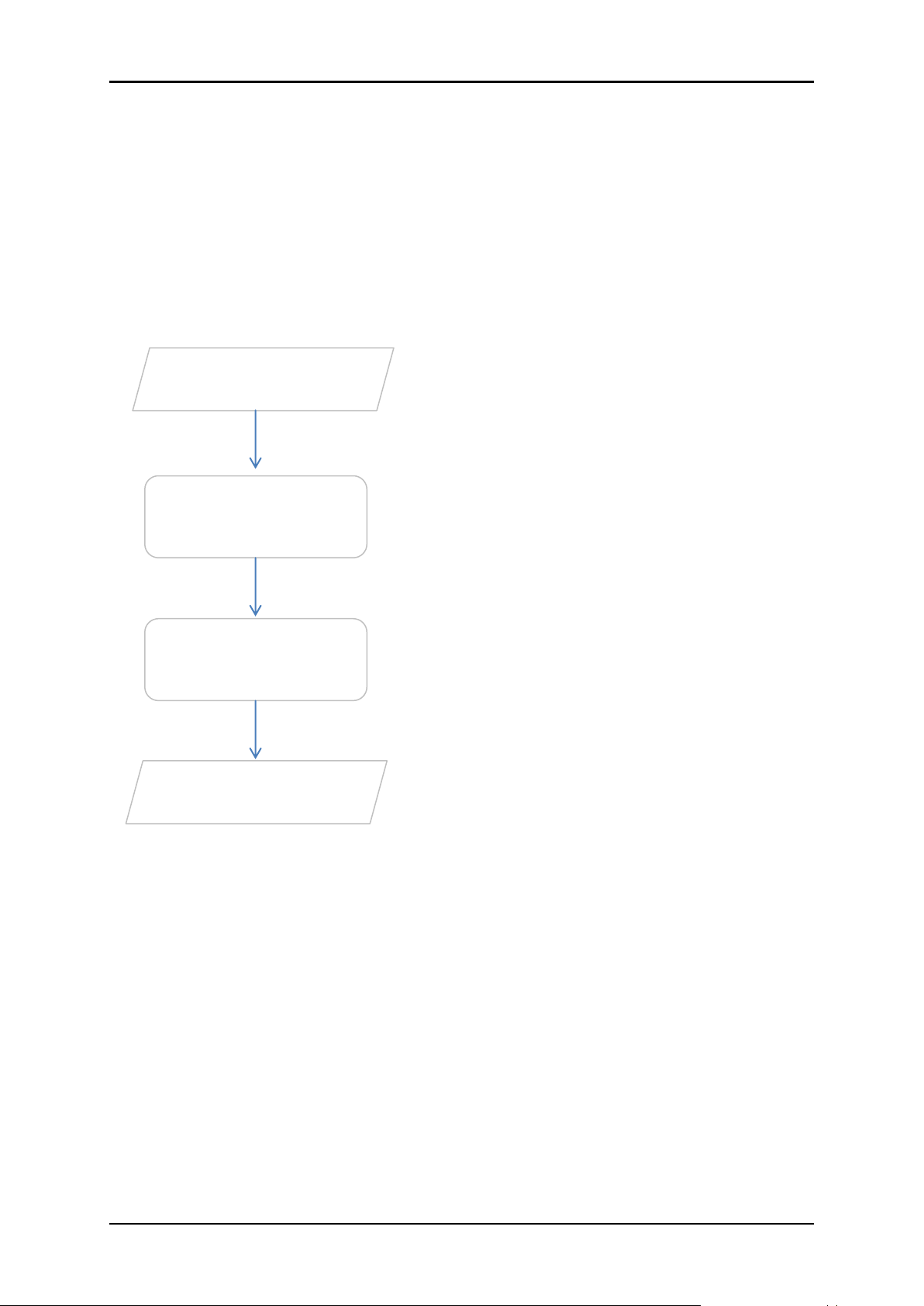
Connect the telephone cables, Ethernet
cables, and power adapter.
Plan your Network
Set up your
Modem Router
Web User Interface
Use Quick Setup or
Ready to Use
You may refer to the diagram in this user
manual for the suggested network setup.
You may configure your modem router’s
wireless settings and other features
through the Web User Interface.
You may now access the internet.
Getting Started
Setting up the device is easy. The flowchart below provides an outline of the
steps needed in order to complete the installation. Brief descriptions appear
beside each step. Detailed instructions are provided in the subsequent
pages.
Page 10 of 44
Page 11
User Manual
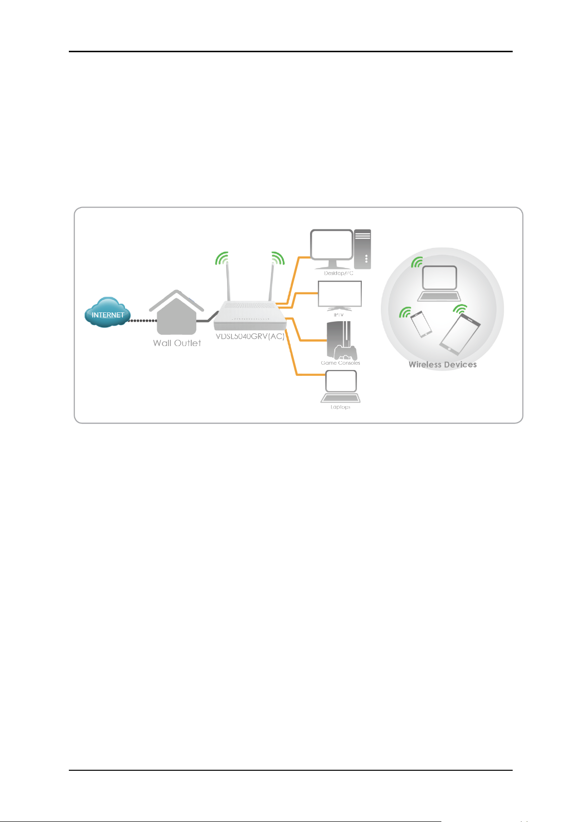
Planning Your Network
Before moving ahead to setup your network, it is a good idea to draw out a
network diagram to help identify your network devices and plan out how to
connect these devices. The illustration below is an example of a network
diagram.
Each port in the modem router can be used for different connections. For
example:
Ethernet 1 – connect to a desktop
Wireless – connect a wireless laptop to the built in wireless access point
To create a network diagram:
For wireless devices, identify the wireless devices you want to include in
the network
For wired devices, identify which modem router port you want to use
for each device
Page 11 of 44
Page 12
User Manual
3 4 1
2
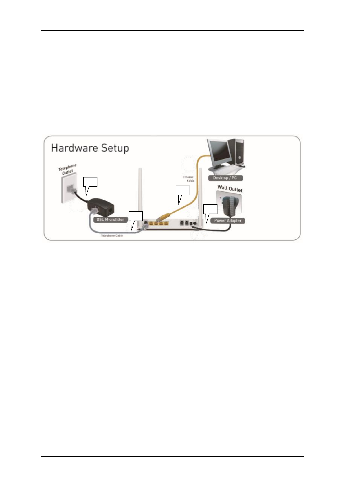
Setup the Device
When installing the modem router, find an area where there are enough
electrical outlets for the modem router, the main computer, and your other
computer devices. For those PCs you wish to access Internet by this router,
each of them must be properly connected through Cable /VDSL/ADSL
device.
1. Connect the Microfilter to the Telephone Outlet.
2. Using the Telephone cable, connect the Modem to the Microfilter.
3. Using the Ethernet cable, connect the modem to the Computer.
4. Connect the Power adapter to the modem.
5. Power ON the modem. Check and confirm that the Power LED and
Ethernet LED of the router is lit on.
Check the Installation
The control LEDs of the WLAN Router are clearly visible and the status of the
network link can be seen instantly:
1. After hardware installation, at the time of powering on, the Power LED
and Wireless LEDs of this wireless router will keep solid on indicating a
normal status.
Page 12 of 44
Page 13

User Manual
2. When the DSL Port is connected to the VDSL/ ADSL Server and dialed
successfully, the DSL LED will keep solid on all the time.
3. When the Ethernet Port is connected to the computer, the Ethernet LED
will blink all the time.
4. When the pots port is connected to the phone cable and registered
successfully, the phone LED will keep solid on.
Setup the Computer
The default IP address of the Router is 192.168.254.254, the default Subnet
Mask is 255.255.255.0. Both of these parameters can be changed as you
want. In this guide, we will use the default values for description.
Connect the local PC to the LAN port on the Router. There are two ways to
configure the IP address for your PC.
Configure the IP address manually
1. Right-click on My Network Places – Properties, then right-click Local
Area Connection – Properties; double click on TCP/IP Protocol.
2. Configure the network parameters manually. Set the IP address to
192.168.1.xxx (“xxx” range from 2 to 254). The Subnet Mask is
255.255.255.0 and Gateway is 192.168.254.254 (Router’s default IP
address).
Obtain an IP address automatically
Set up the TCP/IP Protocol to Obtain an IP address automatically mode on
your PC.
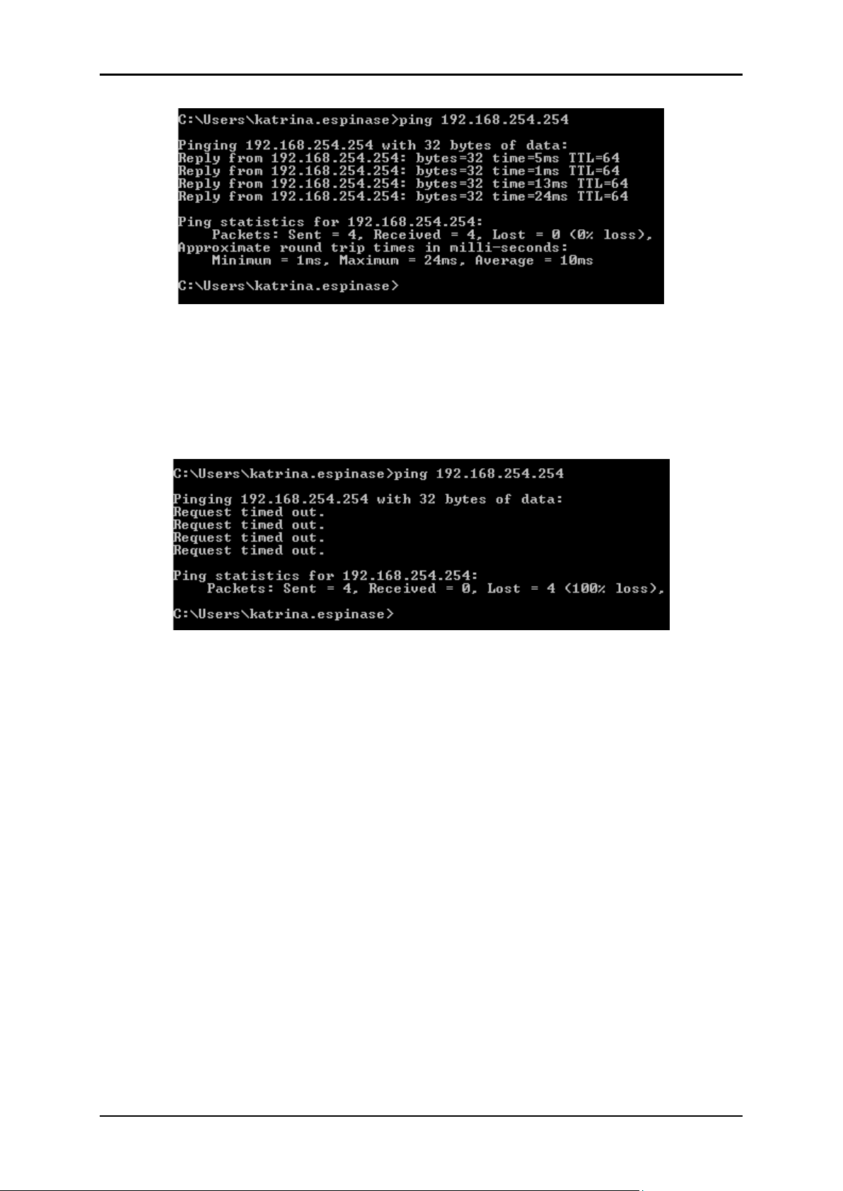
Now, you can run the Ping command in the command prompt to verify the
network connection between your PC and the Router. Open a command
prompt, and type in ping 192.168.254.254, then press Enter.
Page 13 of 44
Page 14
User Manual
If the result displayed is similar to that shown in above figure, it means that the
connection between your PC and the router has been successfully
established.
If the result displayed is similar to that shown in the above figure, it means that
your PC is not connected to the router. Check it by following below steps:
Is the connection between your PC and the Router correct?
If correct, the LAN port on the Router and LED on your PC’s adapter should
be lit.
Is the TCP/IP configuration for your PC correct?
Since the Router’s IP address is 192.168.254.254, your PC’s IP address must be
within the range of 192.168.1.2 ~ 192.168.1.254, the Gateway must be
192.168.1.1.
Page 14 of 44
Page 15

User Manual
The Web User Interface (GUI)
The Web User Interface allows you to configure all of your modem router’s
functionalities. This chapter introduces how to configure the basic functions of
your router so that you can surf the Internet.
Accessing Web Page
Set up the TCP/IP Protocol to Obtain an IP address automatically mode on
your PC.
1. Open a web browser (i.e. Google Chrome or Internet Explorer). On the
address bar, type the default IP: 192.168.254.254 and press Enter. You
will be redirected to the Login page of your modem router’s Web User
Interface.
2. Type the username and password in the login page.
3. Click Login button or press Enter key. You will be directed into the
Home page. Now, you have logged into the web interface of the
router.
Page 15 of 44
Page 16

User Manual
FIELD
DESCRIPTION
Connection
Name
Once you change your internet access, you should choose new connection
Enable VLAN
Support VLAN and make every device independently.
Basic Setup
In the navigation bar, click Basic Setup. The tab Setup contains WAN, Wireless
and VoIP.
WAN Service
Choose Basic Setup > WAN Service on the left navigation menu, then the
following screen will appear. In this page, you can configure WAN interface
of your router.
The following table describes the parameters of the above page.
Subnet Mask: This is used to define the device IP classification for the chosen
IP address range. 255.255.255.0 is a typical net mask value for Class C
networks. Generally it is provided by your ISP.
Default Gateway: This is the IP address of the host router that resides on the
external network and provides the point of connection to the next hop
towards the Internet. This can be a DSL modem, Cable modem, or a WISP
gateway router. The router will direct all the packets to the gateway if the
destination host is not within the local network.
Page 16 of 44
Page 17

User Manual
Note: (1) If finished with the Setup, you can check it out (Status > WAN
> Network, and Status should be Connected) as follows:
(2) Check the XDSL Status (Status > WAN > xDSL), and Status should be
up as follows.
(3) Check your LAN Port speed (Status > LAN > Ethernet) as follows:
Page 17 of 44
Page 18

User Manual
(4) Check the WAN statistic (Status > WAN > Ethernet) as follows:
(5) Check the LAN statistic (Status > Statistics > LAN) as follows:
(6) Check all the data of the XDSL, Current rate, Max rate, etc. (Status >
Statistics > xDSL) as follows:
Page 18 of 44
Page 19

(7) Check the ARP data (Status > Statistics > ARP) as follows:
(8) Check the xTM data (Status > Statistics > xTM) as follows:
User Manual
(9) Check the VoIP data (Status > Statistics > VoIP) as follows:
Page 19 of 44
Page 20

User Manual
FIELD
DESCRIPTION
Device
information
Including Product Type, Device ID, Hardware Version, Software Version, MAC
Address, and System up time.
WANNetwork
Including IPv4/IPv6 Connection Status, DS-Lite Status.
WANEthernet
You can check the wan data about received and Transmitted.
XDSL
If the line is XDSL access, you can check the status,
LAN-Network
The up stand for normal.
LAN-Ethernet
The LAN Host and IPv6 LAN host will be displayed
WLAN
Every interface information in LAN can be check such as status, speed and
duplex
DHCP Client
The info about SSID index, SSID, BSSID, Status Authentication Mode and
Encryption Mode can be checked
Statistic-WAN
The host information including host name, MAC Address, IP Address, lease
time
Statistic-LAN
Received and transmitted data pass through wan.
StatisticWLAN
The data pass through LAN
xDSL
Different SSID received and transmitted packages
ARP
Including the Status about the DSL up/down etc.
Voice Status
It is an address table about the LAN pc.
The following table describes the parameters of the Status.
Wireless
Basic Configuration 2.4GHz
Choose Basic Setup > Wireless > Basic Configuration 2.4GHz on the left
navigation menu, then the following screen will appear. SSID can be
Page 20 of 44
Page 21

User Manual
FIELD
DESCRIPTION
Choose SSID
In 2.4GHz, you can choose from SSID 1 to SSID 4
In 5GHz, you can choose from SSID 5 to SSID 8
Enable SSID
Enable the 2.4 GHz Wireless Network. If you don’t want to use the wireless
function, just deselect the box.
Enable
Isolation
Every SSID is independent, they cannot access each other.
Hide SSID
Select Hide SSID, and your SSID will not broadcast. Your SSID won’t display on
your wireless device when you scan for local wireless network list and you
need to manually join the network.
SSID
Service Set Identifier used to identify your 802.11 wireless LAN should be
specified while operating, All the client devices within the range will receive
broadcast messages from the access point advertising this SSID.
configured in this section. You can change the preset wireless network name
(SSID). Click the Apply button to save the changes you have made.
The following table describes the parameters of this page.
Basic Configuration 5GHz
Choose Basic Setup > Wireless > Basic Configuration 5GHz. The WLAN page
that is displayed contains Choose SSID, Enable SSID, Enable Isolation, Hide
SSID, BSSID and Choose Country. Please refer to the parameters above. You
can change the preset wireless network name (SSID). Click the Apply button
to save the changes. After that, all your wireless devices must use the new
SSID to connect to the modem router.
Page 21 of 44
Page 22

User Manual
Wireless Security Setting
Choose Basic Setup > Wireless > Security Setting. The page that is displayed
contains Choose SSID, Authentication (Generally choose WPA-PSK/WPA2-PSK
MIXED), WPA Preshare Key, Encryption (Generally choose AES). If it works
2.4GHz, you should choose SSID 1-SSID 4, and then set your own password in
the WPA Preshare key. If it works on 5GHz, you should choose SSID 5-SSID8,
and then set your own password in the WPA Preshare key.
Page 22 of 44
Page 23

User Manual
VOIP
Basic Setup
Choose Basic Setup > VoIP > Basic Setup on the left navigation menu and the
following page appears.
Page 23 of 44
Page 24

User Manual
Advanced Setup
In the navigation bar, click Advanced Setup. The tab Advanced contains
Wireless, NAT, Parental Control, Routing, and Quality of Service.
Wireless
In the navigation bar, click Advanced Setup > Wireless. The tab wireless
contains WPS Configuration 2.4GHz, and WPS Configuration 5GHz.
WPS configuration 2.4GHz
Click Advanced Setup > Wireless > WPS Configuration 2.4GHz in the left pane,
the page shown in the following figure appears. You can use WPS (Wi-Fi
Protected Setup) feature to add a new wireless device to your existing
network quickly.
There are two ways for the wireless client to establish the connection with the
modem through WPS.
Method 1. Use the WPS Button
Use this method if your client device has a WPS button.
(1) Press the WPS button the modem router for 1 second.
Page 24 of 44
Page 25

User Manual
(2) Press the WPS button of the client device directly.
(3) The WPS LED flashes for about 2 minutes during the WPS process.
(4) When the WPS LED is on, the client device has successfully
connected to the modem router.
Method 2. Enter the client device’s PIN on the modem router
(1) Keep the default WPS status as Enabled and select the PIN Code
radio button.
(2) Choose AP Role: Register and enter the client device’s PIN in the
field on the above WPS screen. Then click the Apply button.
(3) Connect successfully will appear on the above screen VAP
information, which means the client device has successfully connected
to the modem router.
Method 3. Enter the modem router’s PIN on your client device
(1) Keep the Router’s PIN status as enabled. Take a note of the Current
PIN of the modem router. You can also click the Generate button to
get a new PIN.
(2) On the client device, enter the modem router’s PIN. (The default PIN
is also printed on the label of the modem router.)
(3) The WPS LED flashes for about two minutes during the WPS process.
(4) When the WPS LED is on, the client device has successfully
connected to the modem router.
WPS configuration 5GHz
Click Advanced Setup > Wireless > WPS Configuration 5GHz in the left
pane, the page shown in the following figure appears.
Page 25 of 44
Page 26

User Manual
NAT
Port Forwarding
Click Advanced Setup > NAT > Port Forwarding in the left pane, the page
shown in the following figure appears.
Port Forwarding can be used for setting up public services in your local
network, such as HTTP, FTP, DNS, POP3/SMTP and Telnet. Different service uses
different service port. Port 80 is used in HTTP service, port 21 in FTP service, port
25 in SMTP service and port 110 in POP3 service. Please verify the service port
number before the configuration. WAN IP: 183.39.154.141
Follow the steps below to configure the Virtual server rules:
(1) Assign a static IP address to your PC, for example 192.168.1.100.
Page 26 of 44
Page 27

(2)Go to Advanced Setup > NAT > Port Forwarding, click Add.
User Manual
(3)Choose enable, description, external port, internal port and protocol
will be filled with contents as above. Enter the PC’s IP address
192.168.1.100 in the Internal IP field.
(4)Click Apply to save the settings.
(5)Users in the Internet can enter http:// WAN IP (in this example:
http:// 183.39.154.141) to visit your personal website.
Note: WAN IP should be a public IP address. For the WAN IP is assigned
dynamically by ISP, it is recommended to apply and register a domain name
for the WAN by DDNS.
Port Triggering
Click Advanced Setup > NAT > Port Triggering in the left pane, the page
shown in the following figure appears.
Port triggering is mainly applied to online games, VoIPs and video players.
Common applications include MSN Gaming Zone, Dialpad and Quick Time 4
players, etc.
Page 27 of 44
Page 28

User Manual
Follow the steps below to configure the port triggering rules:
Go to Advanced Setup > NAT > Port Triggering and click Add.
(2)Click applications, and select the desired application. The triggering
port and protocol, the external port and protocol will be automatically
filled with contents. Here we take application AIM Talk as an example.
(3) Click Apply to save the settings.
Note:
(1)You can add multiple port triggering rules according to your network
need.
(2) If the application you need is not listed in the Existing Applications list,
please enter the parameters manually. You should verify the external ports
the application uses first and enter them into External Port field according to
the format the page displays.
Page 28 of 44
Page 29

User Manual
Multi-NAT
Click Advanced Setup > NAT > Multi-NAT in the left pane, the page shown in
the following figure appears.
There are two Types:
(1) One to One In One-to-One mode, the P-334WT maps one ILA to one IGA.
(2) Many to One In Many-to-One mode, the P-334WT maps multiple ILA to
one IGA. This is equivalent to SUA (i.e., PAT, port address translation), ZyXEL's
Single User Account feature that previous ZyNOS routers supported (the SUA
only option in today's routers.
DMZ Host
Click Advanced Setup > NAT > DMZ Host in the left pane, the page shown in
the following figure appears.
Follow the steps below to configure the DMZ Host rules:
(1) Assign a static IP address to your PC, for example 192.168.1.100
Page 29 of 44
Page 30

User Manual
(2) Select the check box to enable DMZ and Enter the IP address
192.168.1.100 in the DMZ Host IP Address filed.
Note: DMZ is more applicable in the situation that users are not clear
about which ports to open. When it is enabled, the DMZ host is totally
exposed to the Internet, which may bring some potential safety
hazard. If DMZ is not in use, please disable it in time.
Parental Control
This function allows you to block inappropriate, explicit and malicious
websites, and control access to specified websites at specified time.
MAC Control
Click Advanced Setup > Parental Control > MAC Control in the left pane, the
page shown in the following figure appears. You can use this function to
come true the control of the surfing time.
This page adds time of day restriction to a special LAN device connected to
the router. Enter the MAC address of the other LAN device. To find out the
MAC address of a Windows based PC, go to command window and type
ipconfig/all.
Page 30 of 44
Page 31

URL & IP Control
User Manual
Click Advanced Setup > Parental Control > URL&IP Control in the left pane,
the page shown in the following figure appears. If you want to control the
website that access, you can setup it in the following page.
Routing
Static Route
Click Advanced Setup > Routing > Static Route in the left pane, the page
shown in the following figure appears.
For example, in a small office, Rouer1 LAN IP: 192.168.1.1, Router 2 LAN IP:
192.168.1.2 my PC (192.168.1.100) can surf the Internet, but I also want to visit
my company’s server (172.30.30.1). Now I have a switch and another router. I
Page 31 of 44
Page 32

User Manual
FIELD
DESCRIPTION
Destination IP
The destination IP address that you want to assign to a static route.
This IP address cannot be on the same subnet with the WAN IP or
LAN IP of the router. In the example, the IP address of the company
network is the destination IP address, so here enters 172.30.30.1.
Subnet Mask
Determines the destination network with the destination IP address.
If the destination is a single IP address, enter 255.255.255.255;
otherwise, enter the subnet mask of the corresponding network IP.
In the example, the destination network is a single IP, so here enters
255.255.255.255.
Gateway
The IP address of the gateway device to which the data packets will be
sent. This IP address must be on the same subnet with the router’s IP
which sends out the data. In the example, the data packets will be sent to
the LAN port of Router 2 and then to the Server, so the default
gateway should be 192.168.1.2
connect the devices as shown in the following figure so that the physical
connection between my PC and my company’s server is achieved. To surf
the Internet and visit my company’s network at the same time, I need to
configure the static routing.
(1) Go to Advanced Setup > Routing > Static Route and Click add.
(2) Select your current WAN Interface and choose from connection
name.
(3) Click Add to add a new static routing entry. Finish the settings
according to the following explanations:
(4) Select the check box to enable this entry.
(5) Click Apply to save the settings.
Page 32 of 44
Page 33

User Manual
FIELD
DESCRIPTION
Active
Select active, the router communicates with other RIP-enabled devices.
Port
The router interface that uses RIP.
Version
Choose the interface version that receives RIP messages. You can choose
off,RIPv1, RIPv2-B, RIPv2-M,or Both.
Choose RIPV1 indicates the router receives and broadcasts RIP v1
messages.
Choose RIPv2-B, RIPv2-M indicates the router receives and
broadcasts RIP v2 messages.
Choose Both indicates the router receives and broadcasts RIP v1 and
RIP v2 messages.
Choose off indicates the router can’t receive and broadcasts RIP v1
and RIP v2 messages.
Dynamic Route
Click Advanced Setup > Routing > Dynamic Route in the left pane, the page
shown in the following figure appears.
The following table describes the parameters of this page.
IPv6 Static Route
Click Advanced Setup > Routing > IPv6 Static Route in the left pane, the
page shown in the following figure appears. The setup refers to Static route.
Page 33 of 44
Page 34

User Manual
IPv6 Dynamic Route
Click Advanced Setup > Routing > IPv6 Static Route in the left pane, the
page shown in the following figure appears. The setup refers to Dynamic
route.
Quality of Service
QoS Queue
Click Advanced Setup > Quality of Service > QoS Queue in the left pane. The
page shown in the following figure appears.
Page 34 of 44
Page 35

User Manual
QoS Classification
Click Advanced Setup> Quality of Service> QoS Classification in the left
pane, the page shown in the following figure appears.
Page 35 of 44
Page 36

User Manual
Applications
DNS
Click Applications > DNS >Dynamic DNS in the left pane, the page shown in
the following figure appears Most ISPs (Internet service providers) assign a
dynamic IP address to the router and you can use this IP address to access
your router remotely. However, the IP address can change any time and you
don’t know when it changes. In this case, you might need the DDNS
(Dynamic Domain Name Server) feature on the router to allow you and your
friends to access your router and local servers (FTP, HTTP, etc.) using domain
name, in no need of checking and remembering the IP address.
Page 36 of 44
Page 37

User Manual
Management
Reboot
Click Management > Reboot in the left pane, the page shown in the
following figure appears and click the reboot button the router will restart.
Account Management
Passwords
Click Management > Account Management > Passwords, the page shown in
the following figure appears. You can modify the username and password
by yourself.
Page 37 of 44
Page 38

User Manual
Line Test
Click Management > Account Management > Line Test, the page shown in
the following figure appears.
Tools
Ping Route
Click Management > Tools > Ping route, the page shown in the following
figure appears. You can ping the host address, and learn the information of
the host.
Page 38 of 44
Page 39

User Manual
Router Care Tips
1. Do not deface the router.
2. Do not use any power adapters with the router other than the supplied
adapter as it may damage the device rendering it unusable.
3. Do not let the router get wet, when water gets in contact with the router,
the internal components can corrode which breaks down the router.
4. Install the router on a flat surface and ensure that there is enough space
for air to circulate.
5. Avoid dropping the router, depending on the surface where it lands, the
router can get cracked casing or internal components may get
dislodged affecting its functionality.
6. Clean the router's casing with a soft damp cloth and remove dust that
may cover the router casing's ventilation regularly.
7. Turn off the router and disconnect the power adapter from the power
outlet if it will be unattended for a long time.
Page 39 of 44
Page 40

User Manual
Safety Precautions
Do not open, service, or change any component.
Only qualified technical specialists are allowed to service the
equipment.
Observe safety precautions to avoid electric shock
Check voltage before connecting to the power supply. Connecting to
the wrong voltage will damage the equipment.
Page 40 of 44
Page 41

User Manual
Page 41 of 44
Page 42

User Manual
Page 42 of 44
Page 43

User Manual
Page 43 of 44
Page 44

User Manual
Copyright © 2017 Aztech Technologies Pte Ltd (CRN:199800635M). All rights reserved.
Page 44 of 44
 Loading...