

Page 1

MDP3858U Series
MDP3858UE Series
PCI 56K MODEM
Users Manual
Version 1.0
Page 2
Contents
○○○○○○○○○○○○○○○○○○○○
Preface .......................................................................
Introduction ................................................................
Before you begin ..........................................................
2.1 Minimum System Requirements ...............................................
2.2 Safety Precaution ...................................................................
2.3 Installation Notes ...................................................................
Setting Up the Modem Card .........................................
3.1 Installing the Modem Card ......................................................
3.2 Connecting the Modem Card...................................................
Installing the Modem Drivers .........................................
4.1 For Windows® 95 ..................................................................
4.2 For Windows
®
98 ..................................................................
4
5
6
6
6
7
8
8
11
14
14
17
4.3 For Windows NT®4.0 .............................................................
Testing the Modem Card................................................
5.1 For Windows® 95/98 .............................................................
5.2 For Windows NT
®
4.0 ............................................................
19
20
20
23
Page 3
Frequently Asked Questions ..........................................
24
A.1 Technical Terms ....................................................................
A.2 Common Questions ...............................................................
Technical Specifications ................................................
TAD Connection .........................................................
24
25
32
34
P/N: 040-512377-101
Page 4
Chapter 1 Introduction
Preface
This manual covers the models MDP3858SP-U, MDP3858V-U and MDP3858-U for
MDP3858U series as well as MDP3858SP-UE, MDP3858V-UE and MDP3858-UE for
MDP3858UE series.
This manual gives you a step-by-step guide of the following:
1. Installation of your modem card to your computer
2. Connection to the phone line for internet
3. Installation of modem drivers required to run the modem
4. Testing of the modem
The section - Frequently Asked Questions (FAQ) will explain some of the
technical terms used in this manual, as well as the possible solutions for some of
the commonly asked questions by users.
For further technical details on your card, you may refer to the ReadMe.txt file
found in your MDP3858 Installation Disk/CD.
○○○○○○○○○○○○○○○○○○○○○○○○○○○○○○○○○○○○○○○○○
4
Page 5

Chapter 1 Introduction
○○○○○○○○○○○○○○○○○○○○
Introduction
Congratulations on your purchase of 56K PCI Modem!
With the 56K PCI Modem alone, you can perform a comprehensive range of modem-
related functions including data communications, sending and receiving of faxes.
Depending on the model that you have bought, you can also do telephone /
speakerphone operations.
The intensive demands of todays Internet applications will no longer be a bottleneck.
Using the 56K PCI Modem, you can now download graphic intensive web pages, high
bandwidth audio and video files as well as large file size software programs at speeds of
up to 56Kbps.
○○○○○○○○○○○○○○○○○○○○○○○○○○○○○○○○○○○○○○○○○
5
Page 6
Chapter 2 Before You Begin
○○○○○○○○○○○○○○○○○○○○
Before You Begin
This chapter contains information that your need to know before installing your
modem card. They are the basic system requirements needed for your modem card to
run, the safety rules to follow, as well as the installation guidelines.
2.1 Minimum System Requirements
• IBM PC-based computer with Pentium
®
166 processor
• PCI Bus slot
• 16MB RAM
• 10MB hard disk space (system files and modem drivers only)
• CD-ROM drive
• Windows
®
95/98 / NT®4.0
2.2 Safety Precaution
• Do not remove your card from its protective bag until you are ready to
install it.
• Always try to hold your card by its edges. Avoid touching any electronic
components on your card.
• Static electricity can cause permanent damage to your card. To prevent
such a damage, you must ground yourself during the installation:
○○○○○○○○○○○○○○○○○○○○○○○○○○○○○○○○○○○○○○○○○
6
Page 7

Chapter 2 Before You Begin
» Use a grounding strap - a coiled wire with a clip at one end and an
elastic strap at the other. Wear the strap around your wrist and attach
the clip to any non-painted metal surface of your computer chassis.
» If you do not have a grounding strap, touch any non-painted surface
of your computer chassis before you begin installation, and again
every minute or so until the installation is completed.
2.3 Installation Notes
• Computers come in different shapes and sizes. Therefore, the installation
procedures in this manual apply generally and you should compare the
illustrations here with your computer.
• A Philips screwdriver is required.
• The documentation for your computer should come in handy during the
installation. Have it ready by your side.
• If you have an existing non Plug-and-Play modem installed in your computer,
you must first un-install its modem drivers before you remove the card.
Refer to the documentation of your existing modem for details.
If your existing modem is Plug-and-Play, you may proceed to install your
new modem.
○○○○○○○○○○○○○○○○○○○○○○○○○○○○○○○○○○○○○○○○○
7
Page 8
Chapter 3 Setting Up the Modem Card
○○○○○○○○○○○○○○○○○○○○
Setting Up Your Modem Card
This chapter contains information on how to install the modem card and the
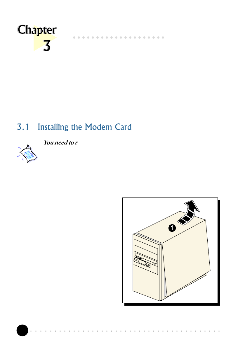
3.1 Installing the Modem Card
You need to remove any existing modem installed in your computer.
If your modem is non Plug-and-Play, you need to un-install its
modem drivers before you remove it. Check your existing modem
documentation for details on this.
Power off your computer and any connected devices before installing
your modem!
telephone line to your computer.
¶ Remove the cover of your
computer.
○○○○○○○○○○○○○○○○○○○○○○○○○○○○○○○○○○○○○○○○○
8
Page 9
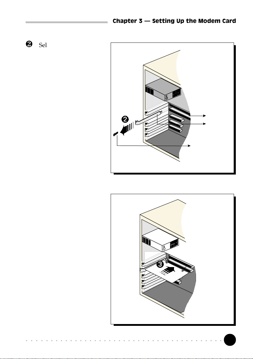
· Select an available PCI
Bus slot and remove its
cover plate. Keep the
mounting screw to
secure your card later.
Chapter 3 Setting Up the Modem Card
PCI Bus Slot
Cover Plate
Mounting Screw
¸ Align your card with
the selected PCI Bus
slot and firmly push it
into the slot. If the card
does not slide in, do
not force it. Make sure
that the card is lined up
properly and try again.
○○○○○○○○○○○○○○○○○○○○○○○○○○○○○○○○○○○○○○○○○
9
Page 10
Chapter 3 Setting Up the Modem Card
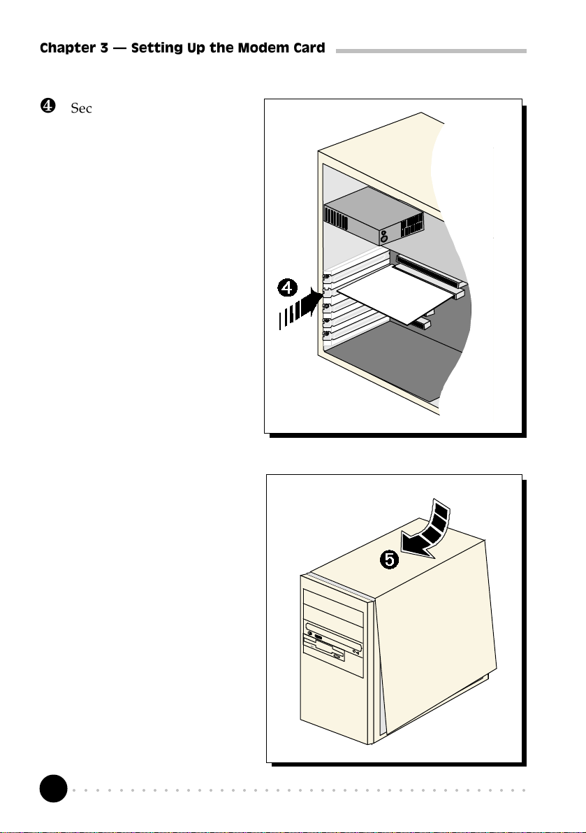
¹ Secure your card to your
computer chassis with the
mounting screw.
º Replace the cover of your
computer.
○○○○○○○○○○○○○○○○○○○○○○○○○○○○○○○○○○○○○○○○○
10
Page 11
Chapter 3 Setting Up the Modem Card
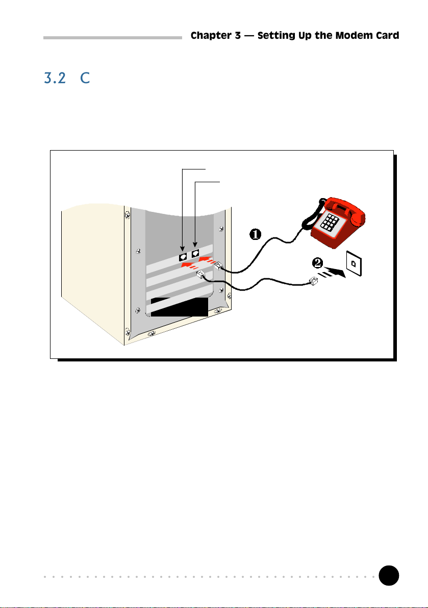
3.2 Connecting the Modem Card
3.2.1 For MDP3858V-U/V-UE, MDP3858-U/-UE users
LINE - to Telephone Wall Socket
PHONE - from Telephone set
T elephone
set
Telephone W all
Socket
¶ Connect a telephone set to the modem card.
(This optional connection eliminates the need to switch between your telephone set
and your modem card if they are sharing the same telephone wall socket)
· Connect one end of the telephone extension cord to the modem card and
the other end to the telephone wall socket.
This completes the setting up of your modem. Please proceed to the next chapter
to install your modem drivers.
○○○○○○○○○○○○○○○○○○○○○○○○○○○○○○○○○○○○○○○○○
11
Page 12

Chapter 3 Setting Up the Modem Card
3.2.2 For MDP3858SP-U/SP-UE users
MIC IN– to Microphone
LINE-OUT
Audio cable
LINE – to Telephone Wall Socket
PHONE – from Telephone set
T elephone
extension cord
Microphone
Active
speakers
¶ Connect a telephone set to the modem card.
(This optional connection eliminates the need to switch between your telephone set
and your modem card if they are sharing the same telephone wall socket)
T elephone
set
T elephone
Wall
Socket
· Connect one end of the telephone extension cord to the modem card and
the other end to the telephone wall socket.
¸ Connect a microphone to your modem card.
(This optional connection allows you to speak/sing over the microphone during
speakerphone conversations)
¹ Connect your active speakers to your modem card.
This connection is required to receive sound output from your modem card. Before
you make use of this LINE-OUT jack, you need to run the Set Audio Output Utility
to configure your modems sound output from Buzzer to Line-Out option.
○○○○○○○○○○○○○○○○○○○○○○○○○○○○○○○○○○○○○○○○○
12
Page 13

Chapter 3 Setting Up the Modem Card
i) From Windows taskbar, click Start > Programs> MDP3858 Modem Information
> Set Audio.
ii) From the dialog prompt, select Line-Out.
To configure back to buzzer, run the same utility again and click the Buzzer option.
º Alternatively, if you have a sound card (with speakers attached), you may
want to externally connect an audio cable from this LINE-OUT jack of
your modem card to the LINE-IN jack of your sound card.
This connection is required if you want to do voice playback.
For voice recording, the microphone must be connected to the MIC-IN
Jack of your compatible sound card.
Instead of using the audio cable, you may also use a TAD cable to
internally connect your modem card and your compatible sound card
as described in Appendix C - TAD Connection. For this connection,
all devices (e.g. microphone, speakers) are to be connected to your
sound card, regardless of voice recording or speakerphone.
This completes the setting up of your modem. Please proceed to the next chapter
to install your modem drivers.
○○○○○○○○○○○○○○○○○○○○○○○○○○○○○○○○○○○○○○○○○
13
Page 14

Chapter 4 Installing the Modem Drivers
○○○○○○○○○○○○○○○○○○○○
Installing the Modem Drivers
This chapter contains information on how to install the modem drivers under
Windows® 95/98 and Windows NT® 4.0.
If problems are encountered with connection or performance of this
modem, please ensure that the country setting is correct for your
location. In some cases, the country is set to match the Operating
System selected and may need to be re-selected to match your exact
location. For instructions on how to change the setting, refer to
Appendix A - Frequently Asked Questions I am using my system
with the modem card in another country. Is there any settings that
need to be changed ?.
4.1 For Windows® 95
1. Power on your computer to start Windows® 95.
Windows® 95 will
detect the newly
installed modem and
an Update Device
Driver Wizard window
will appear.
Place your Installation
CD/floppy disk into
the CD-ROM drive/
floppy disk drive.
Click Next.
○○○○○○○○○○○○○○○○○○○○○○○○○○○○○○○○○○○○○○○○○
14
Page 15

Chapter 4 Installing the Modem Drivers
2. Windows® 95 will now prompt you that the modem drivers have been found.
Click Finish to continue with the installation.
3. When the Insert Disk window appears, click OK.
4. The Copying Files... window will appear.
○○○○○○○○○○○○○○○○○○○○○○○○○○○○○○○○○○○○○○○○○
15
Page 16

Chapter 4 Installing the Modem Drivers
For drivers that are found in CD, in the Run text box, type "D:\".
(Assuming your CD-ROM drive is D. If not, substitute drive letter accordingly)
For drivers that are found in diskette, in the Run text box, type "A:\".
(Assuming your floppy disk drive is A. If not, substitute drive letter accordingly)
Click OK. Restart your system, if prompted.
This completes the installation of the modem drivers in Windows® 95. Proceed
to the next chapter to test your modem.
○○○○○○○○○○○○○○○○○○○○○○○○○○○○○○○○○○○○○○○○○
16
Page 17

Chapter 4 Installing the Modem Drivers
4.2 For Windows® 98
1. Power on your computer to start Windows® 98. Windows® 98 will detect
the newly-installed modem and an Add New Hardware Wizard window
will appear.
Place your Installation
CD/floppy disk into
the CD-ROM drive/
floppy disk drive.
Click Next.
2. The next window prompt will ask for your modem drivers.
Click the option
Search for the best
driver for your device
(Recommended).
Click Next.
○○○○○○○○○○○○○○○○○○○○○○○○○○○○○○○○○○○○○○○○○
17
Page 18

Chapter 4 Installing the Modem Drivers
3. At the next prompt, select the source of your drivers.
If your drivers are found in CD, click the option CD-ROM drive.
It your drivers are found in diskettes, click the option Floppy disk drives.
Click Next.
4. To start the drivers installation, click Next again.
5. To complete the drivers installation, click Finish and restart your system, if
prompted.
This completes the installation of the modem drivers in Windows® 98. Proceed
to the next chapter to test your modem.
○○○○○○○○○○○○○○○○○○○○○○○○○○○○○○○○○○○○○○○○○
18
Page 19

Chapter 4 Installing the Modem Drivers
4.3 For Windows NT® 4.0
1. Start Windows NT®.
2. Place your Installation CD/floppy disk into the CD-ROM drive/floppy disk
drive.
3. From the Windows NT® taskbar, select Start > Run... .
If your drivers are found in CD, in the Run text box, type:
"D:\Winnt\**Product Name\setup.exe"
(Assuming your CD-ROM drive is D. If not, substitute drive letter accordingly)
** Replace with MDP3858spu (if your product model is MDP3858SP-U)
MDP3858vu (if your product model is MDP3858V-U)
MDP3858u (if your product model is MDP3858-U)
MDP3858spue (if your product model is MDP3858SP-UE)
MDP3858vue (if your product model is MDP3858V-UE)
MDP3858ue (if your product model is MDP3858-UE)
If your drivers are found in diskette, type "A:\setup.exe"
(Assuming your floppy disk drive is A. If not, substitute drive letter accordingly)
Click OK.
4. From the Modem Board Installation Wizard, click Next and select your
product model.
5. Follow any on-screen instructions to complete the software installation.
6. Restart your system.
This completes the installation of the modem drivers in Windows NT® 4.0. Please
proceed to the next chapter to test your modem.
○○○○○○○○○○○○○○○○○○○○○○○○○○○○○○○○○○○○○○○○○
19
Page 20

Chapter 5 Testing the Modem Card
○○○○○○○○○○○○○○○○○○○○
Testing the Modem Card
This chapter contains information on how to test your modem card in
The testing procedures for MDP3858U series and MDP3858UE series
for Windows 95® and 98 are exactly the same. The following
illustrations are only based on the model MDP3858-U, in the
Windows® 95 environment.
5.1 Windows® 95/98
Windows® 95/98 & Windows NT® 4.0.
1. From the Windows taskbar, click
Start > Settings > Control Panel.
○○○○○○○○○○○○○○○○○○○○○○○○○○○○○○○○○○○○○○○○○
20
Page 21

Chapter 5 Testing the Modem Card
2. Double-click the Modems icon.
3. You will see the MDP3858 modem that you installed being listed. Click on
the Diagnostics tab.
○○○○○○○○○○○○○○○○○○○○○○○○○○○○○○○○○○○○○○○○○
21
Page 22

Chapter 5 Testing the Modem Card
4.
Select the COM Port that your
modem is connected to and click
More Info...
5. The More Info... window will appear, showing a list of AT commands. This
means that your modem is now ready to run. Click OK.
(If your modem is not installed
properly, the set of AT commands
will not be listed. You may also
be prompted by an error
message, stating that it was
unable to open the COM Port. If
this happens, refer to the
Appendix A - Frequently Asked
Questions While testing the
modem, the system gave an
error message stating that it was
unable to open the COM Port.)
(The Port Information shown here may differ from what you see on your computer. It is determined
by the COM Port which you connect your modem to)
○○○○○○○○○○○○○○○○○○○○○○○○○○○○○○○○○○○○○○○○○
22
Page 23

Chapter 5 Testing the Modem Card
5.2 Windows NT® 4.0
1. From the Windows taskbar, click Start > Programs > Accessories >
HyperTerminal > HyperTerminal.
2. Key in the required information prompted by the dialog boxes.
3. Click OK after entering any telephone number in the dialog box.
4. At the next dialog prompt, click Cancel.
5. Type "AT " and press Enter. You should see a response, OK.
6. Your modem is now ready to run.
○○○○○○○○○○○○○○○○○○○○○○○○○○○○○○○○○○○○○○○○○
23
Page 24

Appendix A Frequently Asked Questions
○○○○○○○○○○○○○○○○○○○
Frequently Asked Questions
This chapter is divided into two sections: Technical Terms and Common Problems.
Technical Terms will explain some of the technical terms used in this manual.
Common Problems will discuss on the possible solutions to some of the commonly
asked questions by users. Reviewing this chapter can help you solve many problems
and often eliminate the need for telephone assistance.
A.1 Technical Terms
What is TAD ?
TAD stands for Telephone Answering Device. Most modem and sound cards
nowadays come with a built-in TAD connector. Reasons are as folllows:
1. It establishes a link between the modem card and sound card internally.
2. It allows user to leave the microphone connection on the sound card, while
the same microphone can be used during speakerphone conversion.
3. It allows user to leave the speakers connection on the sound card, while the
same speakers can be used for any modem audio output. (see ReadMe.txt
file for the Pin configurations)
What is V.90 ?
V.90 is a new standard approved by the International Telecommunication Union
for 56K analog modems. It is a compromise officially reached between the
two competing standards - X2 (from 3COM/USR) and K56Flex (from
Rockwell/Lucent).
○○○○○○○○○○○○○○○○○○○○○○○○○○○○○○○○○○○○○○○○○
24
Page 25

Appendix A Frequently Asked Questions
What is speakerphone feature ? (for MDP3858SP-U/SP-UE models)
During phone conversations, modem speakerphone feature allows you to speak
over the microphone and receives from the speakers. This feature is only
applicable for MDP3858SP-U/SP-UE models.
A.2 Common Problems
How do I identify the MDP3858 modem card and its drivers ?
MDP3858 has its model name printed on the serial number label located at
the rear of the card.
Alternatively, you can issue an AT13 command using any Telephony Data
Terminal application to get the driver version.
This modem is set to V.90. But why am I getting slow connections to
my ISP ?
Majority of the telephone lines and ISP are already supporting V.90 connections.
However, like all data connection, the connection is sensitive to the amount of
noise present in the phone line. Hence, only very clean phone line can get
high connection rate or throughput. You may want to check with your telephone
provider.
The modem hangs up when an incoming call is received.
Disable the Call Waiting function for the Online Service, Internet Connection
and/or communications software you are using.
When I tried to dial out, the system gave me an error message No
Dial Tone.
Check the Telephone Cable connection. If necessary, plug out the Telephone
Cable and reconnect the cable.
○○○○○○○○○○○○○○○○○○○○○○○○○○○○○○○○○○○○○○○○○
25
Page 26

Appendix A Frequently Asked Questions
There are incomprehensible characters appearing on the screen.
The data, parity and stop bit settings are incorrect. Try using the default values
or check with your ISP.
Why does my modem always connect at 33.6Kbps and not 56Kbps or
V90 ?
Check with your Internet Service Provider (ISP) to ensure that they support
56Kbps or V.90 connections. You must also make sure that your modem card
is using the 56Kbps driver. For modem with Country Selection feature, please
ensure that the modem is set to your local country. To set the country select
feature, see the following question.
I am using my system with the modem card in another country. Is
there any settings that need to be changed ?
Yes. You need to ensure that the country setting for your modem card is
correct for your location. Carry out the following steps:
Windows 95/98
1. From Windows environment, right-click on My Computer icon and click
Properties.
2. Click Device Manager tab and double-click on Modem.
3. Select your product model and click Properties.
4. Click Country Select tab and select your current local country.
Windows NT 4.0
1. From the Windows taskbar, click Start > Settings > Control Panel.
2. Double-click on the HCF Modem Country Select icon.
3. Select your current local country.
○○○○○○○○○○○○○○○○○○○○○○○○○○○○○○○○○○○○○○○○○
26
Page 27

Appendix A Frequently Asked Questions
How do I know that my modem is V.90 ready ?
Windows 95/98
1. From Windows taskbar, click Start > Settings Control Panel.
2. Double-click on Modem icon.
3. Click Diagnostic tab and select your product model.
4. Click More Info... option and you will see ATI 6 displaying V.90
supported and ready.
Windows NT 4.0
1. From Windows taskbar, click Start > Programs > Accessories >
HyperTerminal > HyperTermnial.
2. Key in the required information prompted by the dialogue boxes.
3. Click OK after entering any telephone number in the dialogue box.
4. At the next dialogue box prompt, click Cancel.
5. Type ATI 6 and press Enter.
6. You will see ATI 6 displaying V.90 supported and ready.
How do I un-install the modem drivers installed in the system ?
Windows 95/98/NT 4.0
1. From the Windows taskbar, click Start > Settings > Control Panel .
2. Double-click on the Add/Remove Programs icon.
3. Select your product model and click Add/Remove. (There are 2 files
related to the product, MDP3858 PCI Modem Drivers and MDP3858
PCI Modem Files. You need to remove both of them)
4. Follow the on-line instruction to complete the removal of drivers/file.
○○○○○○○○○○○○○○○○○○○○○○○○○○○○○○○○○○○○○○○○○
27
Page 28

Appendix A Frequently Asked Questions
How do I see the resources listings ?
Windows 95/98
1. From the Windows taskbar, click Start > Settings > Control Panel.
2. Double-click the Modems icon.
3. Click the Diagnostics tab. Select your product model and click More
Info... option.
The IRQ (Interrupt) and memory range (Address) used by the modem will be
listed.
Windows NT 4.0
Run the Windows NT Diagnostics as follows:
1. From the Windows taskbar, click Start > Programs > Administrative Tools
(Common) > Windows NT Diagnostics.
2. From the Diagnostics Window, click Resources tab followed by Devices
tab.
3. Double-click WinAcPci.
The IRQ and memory range used by the modem will be listed.
(The COM Port and IRQ are assigned automatically by the Operating System
during installation. Both the COM Port and IRQ settings cannot be changed
by the user)
My system does not detect the modem when I boot up for the first
time.
Windows 95/98
Make sure your modem is fully inserted into the PCI Bus slot.
However, if you are sure that the modem has been properly installed, do the
following:
1. From the Windows taskbar, click Start > Settings > Control Panel.
2. Double-click the System icon.
3. Click the Device Manager tab.
○○○○○○○○○○○○○○○○○○○○○○○○○○○○○○○○○○○○○○○○○
28
Page 29

Appendix A Frequently Asked Questions
4. Check whether there is any yellow exclamation mark (error) on the modem
devices. If yes, select the device, click Remove and OK. Re-install the
modem drivers.
Windows NT 4.0
Not Applicable.
The Modem Board Installation Wizard says the driver could not be
installed.
Windows 95/98
Not applicable.
Windows NT 4.0
Make sure that your modem card is fully inserted into the PCI Bus Slot and
install the modem drivers again.
○○○○○○○○○○○○○○○○○○○○○○○○○○○○○○○○○○○○○○○○○
29
Page 30

Appendix A Frequently Asked Questions
I have done a diagnostics test of my modem and there is nothing
wrong with it. However, when I use a communications software, there
seems to be an error. Why?
Windows 95/98/NT 4.0
Try to use a different telephony application like Microsoft Fax to fax a
document. If the sending of a fax is successful, then the fax function of your
modem is working fine.
Try to use Hyperterminal to dial up to a BBS. If the connection is successful,
then the data function of your modem is working fine.
Try exiting the communications software and running it again.
While testing the modem, the system gave an error message saying
that it was unable to open the COM Port.
Make sure that you have closed all communication software (e.g.
Hyperterminal, Dial-up Networking, etc.) when you are doing the diagnostics
test.
However, if there is no communications software running, do the following:
1. From the Windows taskbar, click Start >Settings > Control Panel.
2. Double-click the System icon.
3. Click the Device Manager
tab.
4. Check whether there is any
yellow exclamation mark on
the modem device. If yes,
remove the modem device and
re-install the modem drivers.
○○○○○○○○○○○○○○○○○○○○○○○○○○○○○○○○○○○○○○○○○
30
Page 31

Appendix A Frequently Asked Questions
How do I use the modem speakerphone ? (for MDP3858SP-U/SP-UE
models only)
To use the speakerphone feature, make sure that you have installed, connected
and tested your card as described in Chapter 3, 4 and 5 respectively. Then,
run the Communications Application bundled in your MDP3858 Installation
CD/Disk to use the speakerphone.
Can I make use of the MIC Jack and LINE-IN Jack on my sound card
for speakerphone ? (applicable to MDP3858SP-U/SP-UE and MDP3858V-U/
V-UE models only)
You can make use of the MIC Jack and LINE-IN Jack on your compatible
sound card. Use a TAD cable to internally connect your modem card to your
sound card as described in Appendix C - TAD Connection. The TAD
connection will establish a link between your modem card and sound card. In
this case, you are able connect your microphone and speakers to MIC jack and
LINE-OUT on your sound card to do speakerphone.
○○○○○○○○○○○○○○○○○○○○○○○○○○○○○○○○○○○○○○○○○
31
Page 32

Appendix B Technical Specifications
○○○○○○○○○○○○○○○○○○○○
Technical Specifications
This chapter contains the technical specifications of your card. The information may be
more useful for technically inclined users.
Modem Standards
V.90, K56Flex
V.34+, V.34, V.32bis, V.32, V.22bis, V.22, V.21
Bell 212A, Bell 103
Modem Data Rates
56Kbps (download speed from Internet Service Provider)
33.6Kbps 300bps
Data Throughput
Up to 115.2Kbps (with compression) and 57.6Kbps (without compression)
Error Correction
V.42 LAP-M and MNP2-4
Data Compression
V.42bis and MNP5
Fax Modulations
V.17, V.29, V.27ter, V21 Channel 2 Class 1 and Group 3 Protocol
○○○○○○○○○○○○○○○○○○○○○○○○○○○○○○○○○○○○○○○○○
32
Page 33

Appendix B Technical Specifications
H.324 Video Ready
V.80, V.8bis
Rockwell VRPI
PCI Interface
PCI 2.1 Interface
PCI Plug and Play
PCI Power Management (Wake-Up on Ring through PCI PME# support*)
* only if your system supports ACPI Power Management
The product specifications herein are subject to change without prior
notifications.
○○○○○○○○○○○○○○○○○○○○○○○○○○○○○○○○○○○○○○○○○
33
Page 34

Appendix C TAD Connection
○○○○○○○○○○○○○○○○○○○○
TAD Connection
(for MDP3858SP-U/SP-UE/V-U/V-UE models)
PHONE
LINE
MIC IN
LINE OUT
Microphone or speakers connections must be connected at the sound
card if you are using TAD connection.
Modem TAD PIN Conf iguration
PIN 1
LINE-OUT to Sound Card
PIN 2
Ground
PIN 3
Not Used
PIN 4
MIC-IN from Sound Card
TAD Cable
TAD (on your modem card)
This is a Microphone input cum Line-
Out output connector for use with a
compatible sound card. When
connected, it serves as an audio
communication channel between the
sound card and modem card
for MDP3858SP-U/SP-UE
models only
TAD (on your sound card)
Compatible TAD connector
on the motherboard or
sound card
○○○○○○○○○○○○○○○○○○○○○○○○○○○○○○○○○○○○○○○○○
34
 Loading...