


 Loading...
AXIS 216FD
AXIS 216FD-V
AXIS 216MFD
AXIS 216MFD-V
Fixed Dome Network Camera
Installation Guide
ESPAÑOL ITALIANO DEUTSCH FRANCAIS ENGLISH

AXIS 216FD/216FD-V/216MFD/216MFD-V Installation Guide |
Page 3 |
AXIS 216FD/216FD-V
AXIS 216MFD/216MFD-V
Installation Guide
This installation guide provides instructions for installing the AXIS 216FD, AXIS 216FD-V, AXIS 216MFD and AXIS 216MFD-V Fixed Network Dome Camera on your network. For all other aspects of using the product, please see the User’s Manual, available on the CD included in this package, or from www.axis.com/techsup
Installation steps
1.Check the package contents against the list below.
2.Hardware overview. See page 4.
3.Install the hardware. See page 5.
4.Assign an IP address. See page 7.
5.Set the password. See page 10.
6.Adjust the focus. See page 11.
7.Complete the installation. See page 11.
Important!
This product must be used in compliance with local laws and regulations.
 Package contents
Item |
Models/variants/notes |
|
|
Fixed Dome Network camera |
AXIS 216FD: tamper-resistant casing |
|
AXIS 216FD-V: vandal-resistant casing |
|
AXIS 216MFD: tamper-resistant casing |
|
AXIS 216MFD-V: vandal-resistant casing |
|
|
PS-H indoor power supply |
Europe |
(country specific) |
UK |
|
Australia |
|
USA/Japan |
|
Argentina |
|
Korea |
|
|
Power supply extension cable |
1.8 meters |
|
|
Terminal block connector |
4-pin connector block for connecting external devices to the I/O terminal |
|
connector |
|
|
Mounting kit |
Screwdriver for tamper-proof screws |
|
Tamper-proof screws |
|
Drill template |
|
|
CD |
AXIS Network Video Product CD, including product documentation, |
|
installation tools and other software |
|
|
Printed Materials |
AXIS 216FD/216FD-V/216MFD/216MFD-V Installation Guide (this document) |
|
Axis Warranty Document |
|
|
ENGLISH
Page 4 |
AXIS 216FD/216FD-V/216MFD/216MFD-V Installation Guide |
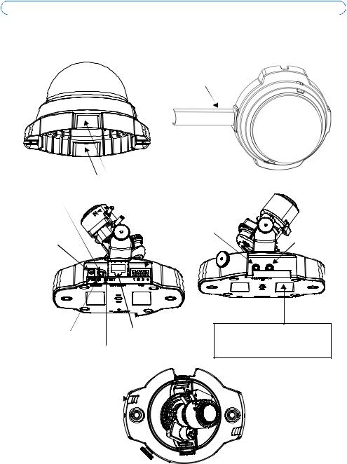
 Hardware overview
16mm cable conduit (not supplied) fitted to
AXIS 216FD-V/216MFD-V
|
Cover plates |
Control button |
I/O terminal connector |
|
(see page 14) |
|
Audio out |
Power connector |
Audio in |
(see page 14) |
|
Power |
Network connector |
indicator LED |
(see page 14) |
|
Network indicator LED
Product ID & Serial number (S/N). The serial number may be required during the installation.
Status indicator LED
 Microphone
Dimensions
HxWxD = 94 x 144 x 132mm (3.7" x 5.7" x 5.2")
Weight AXIS 216FD/AXIS 216MFD = 425g (0.94 lb) (power supply not included) Weight AXIS 216FD-V/216MFD-V = 580g (1.28 lb) (power supply not included)
AXIS 216FD/216FD-V/216MFD/216MFD-V Installation Guide |
Page 5 |
 Install the hardware
!IMPORTANT! - The casing of the AXIS 216FD/216FD-V/216MFD/216MFD-V is not approved for outdoor use - the product may only be installed in indoor environments.
Mount the camera
The AXIS 216FD/216FD-V/216MFD/216MFD-V can be mounted with the cables routed through the wall/ceiling, or from above or below. There are cover plates for the openings on both sides of the dome cover. The AXIS 216FD-V/216MFD-V can also be fitted with a metal conduit for protecting the cabling when connected via the side openings. See the illustrations on page 4.
1.Using the drill template, drill two holes in the ceiling/wall.
2.Route and connect all the required cables. See Connect the cables, below.
3.Fasten the camera unit to a ceiling or wall, using screws and plugs appropriate for the ceiling/wall material.
4.Ensure the camera is positioned so that the tamper-proof screws can be tightened using the supplied screwdriver.
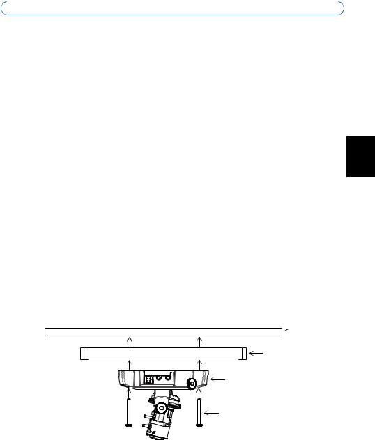
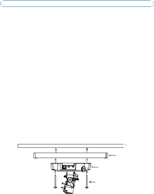
Mounting on a hard ceiling
To mount the AXIS 216FD/216FD-V/216MFD/216MFD-V on a hard ceiling, check that the ceiling material is sturdy enough to hold the weight of the camera.
The camera can also be secured using a plate or board that better carries the weight of the camera, and which is more suitable for securing the screws.
Plate or
 board
board
Hard ceiling
AXIS 216FD/216FD-V 216MFD/216MFD-V
Screws
ENGLISH
The AXIS 216FD/AXIS 216MFD can also be mounted using the AXIS 216FD/AXIS 216MFD Drop Ceiling Mount, which allows the camera to be mounted more discreetly. Please see www.axis.com for all available mounting accessories.

Page 6 |
AXIS 216FD/216FD-V/216MFD/216MFD-V Installation Guide |
Connect the cables
1.Connect the camera to the network using a shielded network cable.
2.Optionally connect external input/output devices, e.g. alarm devices. See page 14 for information on the terminal connector pins.
3.Optionally connect an active speaker and/or external microphone.
4.Connect power, using one of the methods listed below:
•PoE (Power over Ethernet). If available, this is automatically detected when the network cable is connected (see above).
•Connect the supplied indoor power supply to the power connector on the camera.
5.Check that the indicator LED:s indicate the correct conditions. See the table on page 15 for further details. Note that some LEDs can be disabled and may be unlit.
AXIS 216FD/216FD-V/216MFD/216MFD-V Installation Guide |
Page 7 |
 Assign an IP address
Most networks today have a DHCP server that automatically assigns IP addresses to connected devices. If your network does not have a DHCP server the AXIS 216FD/216FD-V/ 216MFD/216MFD-V will use 192.168.0.90 as the default IP address.
If you would like to assign a static IP address the recommended method in Windows is either AXIS IP Utility or AXIS Camera Management. Depending on the number of cameras you wish to install, use the method that best suits your purpose.
Both of these free applications are available on the Axis Network Video Product CD supplied with this product, or they can be downloaded from www.axis.com/techsup
|
|
|
|
ENGLISH |
Method |
Recommended for |
Operating system |
|
|
|
|
|||
|
|
|
|
|
AXIS IP Utility |
Single camera |
Windows |
|
|
|
||||
See page 8 |
Small installations |
|
|
|
|
|
|
|
|
AXIS Camera Management |
Multiple cameras |
Windows 2000 |
|
|
See page 9 |
Large installations |
Windows XP Pro |
|
|
|
Installation on a different subnet |
Windows 2003 Server |
|
|
|
|
|
|
|
Notes:
•If assigning the IP address fails, check that there is no firewall blocking the operation.
•For other methods of assigning or discovering the IP address of the AXIS 216FD/216FD-V/216MFD/ 216MFD-V, e.g. in other operating systems, see page 13.
Page 8 |
AXIS 216FD/216FD-V/216MFD/216MFD-V Installation Guide |
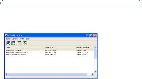
AXIS IP Utility - single camera/small installation
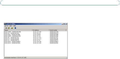
AXIS IP Utility automatically discovers and displays Axis devices on your network. The application can also be used to manually assign a static IP address.
Note that the computer running AXIS IP Utility must be on the same network segment (physical subnet) as the AXIS 216FD/216FD-V/216MFD/216MFD-V.
Automatic discovery
1.Check that the AXIS 216FD/216FD-V/216MFD/216MFD-V is connected to the network and that power has been applied.
2.Start AXIS IP Utility.
3.When the camera appears in the window, double-click it to open its home page.
4.See page 10 for instructions on how to assign the password.
Assign the IP address manually (optional)
1.Acquire an unused IP address on the same network segment as your computer.
2.Select the AXIS 216FD/AXIS 216MFD in the list.
3.Click the button  Assign new IP address to the selected device and enter the IP address.
4.Click the Assign button and follow the instructions.
5.Click the Home Page button to access the camera’s web pages.
6.See page 10 for instructions on how to set the password.
Note:
AXIS 216FD and AXIS 216FD-V will display in AXIS Camera Management as AXIS 216FD. AXIS 216MFD and AXIS 216MFD-V will display in AXIS Camera Management as AXIS 216MFD.
AXIS 216FD/216FD-V/216MFD/216MFD-V Installation Guide |
Page 9 |
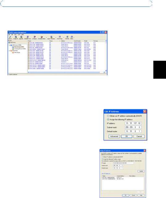
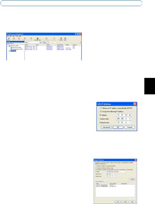
AXIS Camera Management - multiple cameras/large installations
AXIS Camera Management can automatically discover multiple Axis devices, show connection status, manage firmware upgrades and set IP addresses.
ENGLISH
Automatic discovery
1.Check that the camera is connected to the network and that power has been applied.
2.Start AXIS Camera Management. When the AXIS 216FD/AXIS 216MFD appears in the window, double-click it to open the camera’s home page.
3.See page 10 for instructions on how to set the password.
Assign an IP address in a single device
1.Select AXIS 216FD/AXIS 216MFD in AXIS Camera Management and click the Assign IP button. 
2.Select Assign the following IP address and enter the IP address, the subnet mask and default router the device will use.
3.Click the OK button.
Assign IP addresses in multiple devices
AXIS Camera Management speeds up the process of assigning IP addresses to multiple devices, by suggesting IP addresses from a specified range.
1.Select the devices you wish to configure (different models can be selected) and click the Assign IP button. 
2.Select Assign the following IP address range and enter the range of IP addresses, the subnet mask and default router the devices will use.
3.Click the OK button.
Note:
AXIS 216FD and AXIS 216FD-V will display in AXIS Camera Management as AXIS 216FD. AXIS 216MFD and AXIS 216MFD-V will display in AXIS Camera Management as AXIS 216MFD.
Page 10 |
AXIS 216FD/216FD-V/216MFD/216MFD-V Installation Guide |
 Set the password
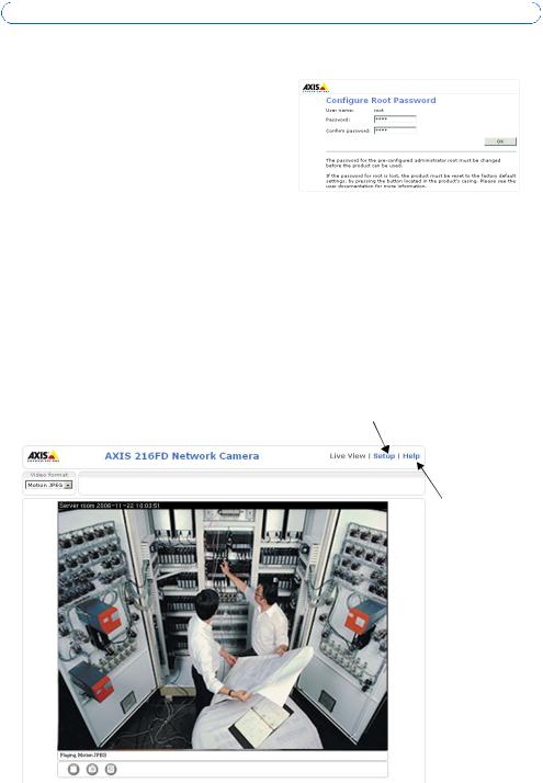
When accessing the AXIS 216FD/216FD-V/ 216MFD/216MFD-V for the first time, the ‘Configure Root Password’ dialog will be displayed.
1.Enter a password and then re-enter it, to confirm the spelling. Click OK.
2.Enter the user name root in the ‘Enter Network Password’ dialog.
Note: The default administrator user name root cannot be deleted.
3.Enter the password as set above, and click OK. If the password is lost, the AXIS 216FD/ 216FD-V/216MFD/216MFD-V must be reset to the factory default settings. See page 16.
4.If required, click Yes to install AMC (AXIS Media Control), which allows viewing of the video stream in Internet Explorer. You will need administrator rights on the computer to do this.
The Live View page of the AXIS 216FD/216FD-V/216MFD/216MFD-V is displayed, with links to the Setup tools, which allow you to customize the camera. Note that both AXIS 216FD/216FD-V will display in the browser as AXIS 216FD and AXIS 216MFD/216MFD-V will display in the browser as the AXIS 216MFD.
Setup - Provides all the tools for configuring the camera to requirements.
Help - Displays online help on all aspects of using the camera.
AXIS 216FD/216FD-V/216MFD/216MFD-V Installation Guide |
Page 11 |
 Adjust the image and focus
Open the Live View page in the web interface and make the following adjustments to the camera:
1.Loosen the locking screw and tilt adjustment screws.
2.Turn the lens to the desired position.
3.Once satisfied, gently tighten the locking screw and tilt adjustment screws to secure the camera’s position.
4.Turn the image balance ring to set the horizontal position.
5.Open the Focus Adjustment page in the Web interface under Basic Configuration > Focus and follow the onscreen instructions. Use the image window to adjust the focus and zoom.
Image |
|
|
balance |
Focus puller |
|
ring |
||
|
||
Tilt adjustment |
|
|
screw |
|
Locking screw
6.To set the focus and zoom,
loosen the zoom and focus pullers anti-clockwise and rotate the rings.
Zoom puller
Tilt adjustment screw
Note:
Due to the dome’s refraction, the image might appear slightly out of focus once the dome has been placed. To compensate, focus on an object slightly closer than the inteded area.
7. Lock the focus and zoom pullers in position by rotating the screws clockwise.
The image can also be fine-tuned for low lighting conditions.
Go to Setup > Video & Image > Advanced and see the online help for more information.
 Complete the installation
1.Rotate the black protective shield inside the dome casing to match the camera’s position.
2.Clean the dome with a dry soft cloth to remove dust and finger prints and use a blower to remove dust from the lens.
3.Mount the dome casing using the supplied tamper-proof screws and screw driver.
4.Now that the dome is in place, double-check that the camera is properly focused.
5.The installation is now complete.
ENGLISH

Page 12 |
AXIS 216FD/216FD-V/216MFD/216MFD-V Installation Guide |
Accessing the camera from the Internet
Once installed, your AXIS 216FD/216FD-V/216MFD/216MFD-V is accessible on your local network (LAN). To access the camera from the Internet, network routers must be configured to allow incoming traffic, which is usually done on a specific port. Please refer to the documentation for your router for further instructions. For more information on this and other topics, visit the Axis Support Web at www.axis.com/techsup

AXIS 216FD/216FD-V/216MFD/216MFD-V Installation Guide |
Page 13 |
Other methods of setting the IP address
The table below shows the other methods available for setting or discovering the IP address. All methods are enabled by default, and all can be disabled.
|
Use in operating |
Notes |
|
|
|
system |
|
|
|
|
|
|
|
|
UPnP™ |
Windows |
When enabled on your computer, the camera is automatically |
|
|
|
(ME or XP) |
detected and added to “My Network Places.” |
|
|
|
|
|
|
|
Bonjour |
MAC OSX |
Applicable to browsers with support for Bonjour. Navigate to the |
|
|
|
(10.4 or later) |
Bonjour bookmark in your browser (e.g. Safari) and click on the |
|
ENGLISH |
|
|
link to access the camera’s web pages. |
|
|
|
|
|
|
|
|
|
|
|
|
AXIS Dynamic DNS |
All |
A free service from Axis that allows you to quickly and simply |
|
|
Service |
|
install your camera. Requires an Internet connection with no |
|
|
|
|
HTTP proxy. See www.axiscam.net for more information. |
|
|
|
|
|
|
|
ARP/Ping |
All |
See below. The command must be issued within 2 minutes of |
|
|
|
|
connecting power to the camera. |
|
|
|
|
|
|
|
View DHCP server |
All |
To view the admin pages for the network DHCP server, see the |
|
|
admin pages |
|
server’s own documentation. |
|
|
|
|
|
|
|
Set the IP address with ARP/Ping
1.Acquire an IP address on the same network segment your computer is connected to.
2.Locate the serial number (S/N) on the AXIS 216FD/216FD-V/216MFD/216MFD-V label.
3.Open a command prompt on your computer and enter the following commands:
Windows syntax |
Windows |
example |
|
|
|
arp -s <IP Address> <Serial Number> |
arp -s 192.168.0.125 00-40-8c-18-10-00 |
|
ping -l 408 -t <IP Address> |
ping -l |
408 -t 192.168.0.125 |
UNIX/Linux/Mac syntax |
UNIX/Linux/Mac example |
|
|
|
|
arp -s <IP Address> <Serial Number> temp |
arp -s 192.168.0.125 00:40:8c:18:10:00 |
|
ping -s 408 <IP Address> |
temp |
408 192.168.0.125 |
|
ping -s |
|
4.Check that the network cable is connected to the camera and then start/restart the camera, by disconnecting and reconnecting power.
5.Close the command prompt when you see ‘Reply from 192.168.0.125: ...’ or similar.
6.In your browser, type in http://<IP address> in the Location/Address field and press Enter on your keyboard.
Notes:
•To open a command prompt in Windows: from the Start menu, select Run... and type cmd. Click OK.
•To use the ARP command on a Mac OS X, use the Terminal utility in Application > Utilities.

Page 14 |
AXIS 216FD/216FD-V/216MFD/216MFD-V Installation Guide |
Unit connectors
Network connector - RJ-45 Ethernet connector. Supports Power over Ethernet. Using shielded cables is recommended.
Power connector - Mini DC connector. 5.1V DC, max 3.8W. See product label for ± connection.
Audio in - 3.5mm input for a mono microphone, or a line-in mono signal (left channel is used from a stereo signal).
Audio out - Audio output (line level) that can be connected to a public address (PA) system or an active speaker with a built-in amplifier. A pair of headphones can also be attached. A stereo connector must be used for the audio out.
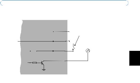
I/O terminal connector - Used in applications for e.g. motion detection, event triggering, time lapse recording and alarm notifications. It provides the interface to:
•1 transistor output - For connecting external devices such as relays and LEDs. Connected devices can be activated by AXIS VAPIX AP, output buttons on the Live View page or by an Event Type. The output will show as active (shown under Event Configuration > Port Status) if the alarm device is activated.
•1 digital input - An alarm input for connecting devices that can toggle between an open and closed circuit, for example: PIRs, door/window contacts, glass break detectors, etc. When a signal is received the state changes and the input becomes active (shown under Event Configuration > Port Status).
•Auxiliary power and GND
Function |
Pin number |
Notes |
Specifications |
|
|
|
|
GND |
1 |
|
|
|
|
|
|
3.3V DC |
2 |
Can be used to power auxiliary equipment. |
Max load = 50mA |
Power |
|
|
|
|
|
Note: This pin can only be used as power out. |
|
|
|
|
|
Digital Input |
3 |
Connect to GND to activate, or leave floating |
Must not be exposed to |
|
|
(or unconnected) to deactivate. |
voltages greater than |
|
|
|
10V DC |
|
|
|
|
Transistor |
4 |
Uses an open-collector NPN transistor with |
Max load = 50mA |
Output |
|
the emitter connected to the GND pin. If used |
Max voltage = 24V DC |
|
|
with an external relay, a diode must be con- |
(to the transistor) |
|
|
nected in parallel with the load, for protection |
|
|
|
against voltage transients. |
|
|
|
|
|
AXIS 216FD/216FD-V/216MFD/216MFD-V Installation Guide
Connection diagram
AXIS 216FD/216FD-V/216MFD/216MFD-V
3.3V |
|
|
|
|
1 o |
|
|
||||||||
|
|
|
|
|
|
||||||||||
|
|
|
|
|
|
e.g. pushbutton |
|||||||||
|
|
|
|
|
|
|
|
|
|
||||||
max. 50mA |
|
|
|
|
2 o |
|
|
|
|
|
|||||
|
|
|
|
|
|
|
|
|
|
|
|
|
|
|
|
|
|
|
|
|
|
|
|
|
|
|
z |
|
|
|
|
|
|
|
|
|
|
|
|
|
|
3 o |
|
|
|
|
|
|
|
|
|
|
|
|
|
||||||||
|
|
|
|
|
|
4 |
|
|
|
|
|
||||
o
Page 15
ENGLISH
LED indicators
LED |
Color |
Indication |
|
|
|
Network |
Green |
Steady for connection to a 100 Mbit/s network. Flashes for network activity. |
|
|
|
|
Amber |
Steady for connection to 10 Mbit/s network. Flashes for network activity. |
|
|
|
|
Unlit |
No network connection. |
|
|
|
Status |
Green |
Steady green for normal operation. |
|
|
Note: The Status LED can be configured to be unlit during normal operation, or to |
|
|
flash only when the camera is accessed. To configure, go to Setup > System |
|
|
Options > LED settings. See the online help files for more information. |
|
|
|
|
Amber |
Steady during startup, during reset to factory default or when restoring settings. |
|
|
|
|
Red |
Slow flash for failed upgrade. |
|
|
|
Power |
Green |
Normal operation. |
|
|
|
|
Amber |
Flashes green/amber during firmware upgrade. |
|
|
|
Page 16 |
AXIS 216FD/216FD-V/216MFD/216MFD-V Installation Guide |
Resetting to the Factory Default Settings
This will reset all parameters, including the IP address, to the Factory Default settings:
1.Disconnect power from the camera.
2.Press and hold the Control button and reconnect power.
3.Keep the Control button pressed until the Power indicator flashes amber (this may take up to 15 seconds).
4.Release the Control button. When the Power indicator displays green (which can take up to 1 minute) the process is complete and the camera has been reset.
5.Re-assign the IP address, using one of the methods described in this document.
It is also possible to reset parameters to the original factory default settings via the web interface. For more information, please see the online help or the user’s manual.
Further information
The user’s manual is available from the Axis Web site at www.axis.com or from the Axis Network Video Product CD supplied with this product.
Tip!
Visit www.axis.com/techsup to check if there is updated firmware available for your AXIS 216FD/216FD-V/216MFD/216MFD-V. To see the currently installed firmware version, see the Basic Configuration web page in the product’s Setup tools.
AXIS 216FD/216FD-V/216MFD/216MFD-V Guide d’installation |
Page 17 |
AXIS 216FD/216FD-V
AXIS 216MFD/216MFD-V
Guide d'installation
Ce guide d'installation vous explique comment installer la AXIS 216FD, AXIS 216FD-V, AXIS 216MFD, et AXIS 216MFD-V sur votre réseau. Pour d'autres informations sur l'utilisation de ce produit, consultez le Manuel de l'utilisateur, disponible sur le CD fourni, ou visitez le site www.axis.com/techsup
Étapes de l'installation
1. Vérifiez le contenu de la livraison à l'aide de la liste ci-dessous.
2.Présentation du matériel. Reportez-vous à la page 18.
3.Installez le matériel. Reportez-vous à la page 19.
4.Paramétrez une adresse IP. Reportez-vous à la page 21.
5.Définissez le mot de passe. Reportez-vous à la page 24.
6.Réglez la mise au point. Reportez-vous à la page 25.
7.Complétez l'installation. Reportez-vous à la page 25.
 Contenu de l'emballage
Important !
Ce produit doit être utilisé conformément aux lois et dispositions locales en vigueur.
Article |
Modèles/variantes/remarques |
|
|
Caméra réseau |
AXIS 216FD: boitier invoyable |
|
AXIS 216FD-V: boitier a l'épreuve du vandalisme |
|
AXIS 216MFD: boitier invoyable |
|
AXIS 216MFD-V: boitier a l'épreuve du vandalisme |
|
|
Alimentation intérieure |
Europe |
PS-H |
Royaume-Uni |
(dépend du pays) |
Australie |
|
États-Unis/Japon |
|
Argentine |
|
Corée |
|
|
Prolongateur de câble |
1,8 mètres |
d’alimentation |
|
|
|
Connecteur pour ter- |
Connecteur 4 broches pour la connexion d'équipements externes au connecteur E/S |
minaux |
|
|
|
Kit de montage |
Tournevis pour vis inviolables |
|
Vis inviolables |
|
Gabarit de perçage |
|
|
CD |
CD de la caméra vidéo réseau Axis comprenant les outils d'installation, les autres logiciels et la |
|
documentation |
|
|
Documentation |
AXIS 216FD/216FD-V/216MFD/216MFD-V Guide d'installation (le présent document) |
|
Document de garantie d'Axis |
|
|
FRANCAIS

Page 18 |
AXIS 216FD/216FD-V/216MFD/216MFD-V Guide d’installation |
 Présentation du matériel
Conduit de 16mm (non fourni) adaptable à AXIS 216FD-V/216MFD-V
Capot plaques
Connecteur pour terminaux E/S Bouton de (reportez-vous à la page 28) commande
Sortie Connecteur audio d'alimentation
(reportez-vous à la page 28) 
|
Connecteur de |
Témoin DEL |
réseau |
d’alimentation Témoin |
(reportez-vous à la |
DEL réseau |
page 28) |
Entrée audio
ID du produit et numéro de série (S/N). Le numéro de série peut être requis pendant l'installation.
Témoin DEL d’état 
Dimensions |
Microphone |
|
H x L x P = 94 x 144 x 132mm |
||
|
||
Poids AXIS 216FD/AXIS 216MFD = 425g (alimentation exclue) |
|
|
Poids AXIS 216FD-V/216MFD-V = 580g (alimentation exclue) |
|
AXIS 216FD/216FD-V/216MFD/216MFD-V Guide d’installation |
Page 19 |
 Installation du matériel
!IMPORTANT! - Le boitier de l'AXIS 216FD/216FD-V/216MFD/216MFD-V n'est pas approuvé pour une utilisation extérieure - Le produit doit être uniquement installé en intérieur.
Montage de la caméra
La caméra AXIS 216FD/216FD-V/216MFD/216MFD-V peut être montée avec les câbles d'alimentation et réseau acheminés dans le mur/plafond, ou depuis le haut ou le bas. Vous disposez de plaques d'obturation pour les ouvertures des deux côtés du capot du dôme. L’AXIS 216FD-V/216MFD-V peut aussi equipé avec un conduit en métal afin de protéger le câblage lorsqu'il est connecté par les ouvertures latérales. Consultez les figures de la page 18.
1. |
Avec le gabarit de perçage, percez deux trous dans le plafond/mur. |
|
|
2. |
Orienter et connecter tous les câbles néccessaires. Voi Branchement des câbles, en bas. |
FRANCAIS |
|
3. |
Fixez la caméra au plafond ou au mur à l'aide des vis et des chevilles appropriées. |
||
|
|||
4. |
Veillez à ce que la caméra soit positionnée de telle manière que les vis inviolables |
|
|
|
puissent être serrées à l'aide du tournevis fourni. |
|
|
|
|
Montage au plafond dur
Pour monter l’AXIS 216FD/216FD-V/216MFD/216MFD-V au plafond dur, vérifier si le materiau du plafond est assez solid pour soutenir le poids de la caméra.
Pour fixer la caméra, vous pouvez utiliser une plaque ou une carte supportant le poids de la caméra, qui sera plus adaptée à la fixation des vis.
Plaque ou
 carte
carte
plafond dur
AXIS 216FD/216FD-V 216MFD/216MFD-V
Vis
The AXIS 216FD/AXIS 216MFD peut aussi être montée à l'aide de l’AXIS 216FD/AXIS 216MFD Drop Ceiling Mount, qui permet de placer la caméra plus discrètement. Voir www.axis.com pour les accessoires de montage disponibles.

Page 20 |
AXIS 216FD/216FD-V/216MFD/216MFD-V Guide d’installation |
Branchement des câbles
1.Connectez la caméra à votre réseau à l'aide d'un câble de réseau blindé.
2.Si vous le souhaitez, connectez des dispositifs externes, par exemple des dispositifs d'alarme. Reportez-vous à la page 28 pour plus d'informations sur les broches du connecteur pour terminaux.
3.Si vous le souhaitez, connectez un haut-parleur actif pour la transmission audio bidirectionnelle.
4.Branchez l'alimentation à l'aide de l'une des méthodes reprises ci-dessous.
•PoE (Alimentation éléctrique par câble ethernet). Si disponible, ceci est automatiquement détecté quand le câble résau est connecté (Voir au -dessus).
•Branchez l'alimentation intérieure fournie au connecteur d'alimentation de la caméra.
5.Vérifiez que les témoins DEL indiquent les conditions correctes. Pour plus d'informations, consultez le tableau à la page 29. Notez que certains témoins DEL peuvent être désactivés et éteints.
AXIS 216FD/216FD-V/216MFD/216MFD-V Guide d’installation |
Page 21 |
 Attribution d'une adresse IP
Aujourd'hui, la plupart des réseaux comportent un serveur DHCP qui attribue automatiquement des adresses IP aux dispositifs connectés. Si ce n'est pas le cas de votre réseau, l'AXIS 216FD/216FD-V/216MFD/216MFD-V utilisera l'adresse IP par défaut 192.168.0.90.
Si vous souhaitez affecter une adresse IP statique, sous Windows nous recommandons l'utilisation de l'application AXIS IP Utility ou de l'application AXIS Camera Management. Selon le nombre de caméras à installer, utilisez la méthode qui vous convient le mieux.
Ces deux applications gratuites sont disponibles sur le CD de la caméra vidéo réseau Axis fourni avec ce produit. Vous pouvez également les télécharger à partir du site www.axis.com/techsup.
Méthode |
Recommandée pour |
Système |
|
|
|
|
d'exploitation |
|
|
|
|
FRANCAIS |
||
|
|
|
|
|
AXIS IP Utility |
Une seule caméra |
Windows |
|
|
|
|
|||
Voir page 22 |
Les petites installations |
|
|
|
|
|
|
|
|
AXIS Camera Management |
Plusieurs caméras |
Windows 2000 |
|
|
Voir page 23 |
Les grandes installations |
Windows XP Pro |
|
|
|
Installation sur un autre sous-réseau |
Windows 2003 Server |
|
|
|
|
|
|
|
Remarques
•En cas d'échec de l'attribution de l'adresse IP, vérifiez qu'aucun pare-feu ne bloque l'opération.
•Pour connaître les autres méthodes d'affectation ou de repérage de l'adresse IP de la caméra AXIS 216FD/216FD-V/216MFD/216MFD-V, par exemple sur d'autres systèmes d'exploitation, reportezvous à la page 24.
Page 22 |
AXIS 216FD/216FD-V/216MFD/216MFD-V Guide d’installation |
AXIS IP Utility - Une seule caméra/petite installation
L'utilitaire AXIS IP Utility détecte et affiche automatiquement les périphériques Axis de votre réseau. Cette application sert également à attribuer manuellement une adresse IP statique.
Notez que l'ordinateur exécutant l'application AXIS IP Utility doit se trouver sur le même segment de réseau (sous-réseau physique) que l'appareil AXIS 216FD/216FD-V/216MFD/ 216MFD-V.
Détection automatique
1.Vérifiez que l'appareil AXIS 216FD/AXIS 216MFD est connecté au réseau et sous tension.
2.Démarrez AXIS IP Utility.
3.Lorsque l'icône de la caméra apparaît dans la fenêtre, double-cliquez dessus pour ouvrir la page d'accueil correspondante.
4.Consultez la page 24 pour savoir comment affecter le mot de passe.
Définissez manuellement l'adresse IP (optionnel)
1.Trouvez une adresse IP inutilisée sur le même segment de réseau que celui de votre ordinateur.
2.Sélectionnez le nom abrégé du produit dans la liste.
3.Cliquez sur le bouton Paramétrer une nouvelle adresse IP de l'outil sélectionné. 
4.Cliquez sur le bouton Paramétrer et suivez les instructions.
5.Cliquez sur le bouton Page d'accueil pour accéder aux pages Web de la caméra.
6.Consultez la page 24 pour savoir comment définir le mot de passe.
Remarque:
AXIS 216FD et AXIS 216FD-V vont être visulaisées dans AXIS IP Utility comme AXIS 216FD, AXIS 216MFD et AXIS 216MFD-V comme AXIS 216MFD.
AXIS 216FD/216FD-V/216MFD/216MFD-V Guide d’installation |
Page 23 |
AXIS Camera Management - Plusieurs caméras/grandes installations
AXIS Camera Management peut détecter automatiquement plusieurs dispositifs Axis, afficher les états de connexion, gérer les mises à niveau du microcode et définir les adresses IP.
Détection automatique
1. |
Vérifiez que la caméra est connectée au réseau et que l'alimentation est activée. |
|
2. |
Démarrez AXIS Camera Management. Double-cliquez sur l'icône de l'AXIS 216FD/ |
|
|
216FD-V/216MFD/216MFD-V lorsqu'elle apparaît dans la fenêtre de façon à ouvrir la |
|
|
FRANCAIS |
|
|
page d'accueil. |
|
|
|
|
3. |
Consultez la page 24 pour savoir comment définir le mot de passe. |
|
Attribuer une adresse IP à un seul dispositif
1.Sélectionnez AXIS 216FD/AXIS 216MFD dans l'application AXIS Camera Management, puis cliquez sur le bouton Assign IP (Affecter une IP). 
2.Sélectionnez Assign the following IP address (Affecter l’adresse IP suivante) et saisissez la plage d’adresse IP, le masque de sous-réseau et le routeur par défaut que le dispositif utilisera.
3.Cliquez sur le bouton OK.
Attribuer des adresses IP à plusieurs dispositifs
AXIS Camera Management accélère le processus d'affectation d'adresses IP sur plusieurs appareils en suggérant les adresses IP parmi une plage spécifiée.
1.Sélectionnez les appareils à configurer (il peut s'agir de plusieurs modèles), puis cliquez sur le bouton Assign IP (Affecter une adresse IP). 
2.Sélectionnez Assign the following IP address range
(Affecter la plage d’adresses IP suivante) et saisissez la plage d'adresses IP, le masque de sous-réseau et le routeur par défaut que les dispositifs utiliseront.
3.Cliquez sur le bouton OK.
Remarque: AXIS 216FD et AXIS 216FD-V vont être visulaisées dans AXIS Camera Management comme AXIS 216FD, AXIS 216MFD et AXIS 216MFD-V comme AXIS 216MFD.
Loading...