


User’s Manual 2006-06-14
Closer to Real, 
DynamixelAX-12

DYNAMIXEL AX-12
Contents
1.Summary
1-1. |
Overview and Characteristics of AX-12 |
Page 2 |
1-2. |
Main Specifications |
Page 3 |
2. |
Dynamixel Operation |
|
2-1. |
Mechanical Assembly |
Page 4 |
2-2. |
Connector Assembly |
Page 5 |
2-3. |
Dynamixel Wiring |
Page 6 |
3. |
Communication Protocol |
|
3-1. Communication Overview |
Page 9 |
|
3-2. |
Instruction Packet |
Page 10 |
3-3. |
Status Packet |
Page 10 |
3-4. |
Control Table |
Page 12 |
4. |
Instruction Set and Examples |
|
4-1. WRITE_DATA |
Page 19 |
|
4-2. READ_DATA |
Page 20 |
|
4-3. REG WRITE and ACTION |
Page 20 |
|
4-4. PING |
Page 21 |
|
4-5. RESET |
Page 22 |
|
4-6. SYNCWRITE |
Page 23 |
|
5. |
Example |
Page 24 |
Appendix |
Page 30 |
|
1

DYNAMIXEL AX-12
1. Dynamixel AX-12
1-1. Overview and Characteristics of AX-12
Dynamixel AX-12 |
The Dynamixel series robot actuator is a smart, modular actuator that incorporates a |
|
gear reducer, a precision DC motor and a control circuitry with networking functionality, |
|
all in a single package. Despite its compact size, it can produce high torque and is |
|
made with high quality materials to provide the necessary strength and structural |
|
resilience to withstand large external forces. It also has the ability to detect and act |
|
upon internal conditions such as changes in internal temperature or supply voltage. |
|
The Dynamixel series robot actuator has many advantages over similar products. |
Precision Control |
Position and speed can be controlled with a resolution of 1024 steps. |
Compliance Driving The degree of compliance can be adjusted and specified in controlling position. |
|
Feedback |
Feedback for angular position, angular velocity, and load torque are available. |
Alarm System |
The Dynamixel series robot actuator can alert the user when parameters deviate from |
|
user defined ranges (e.g. internal temperature, torque, voltage, etc) and can also handle |
|
the problem automatically (e.g. torque off) |
Communication |
Wiring is easy with daisy chain connection, and it support communication speeds up to |
|
1M BPS. |
Distributed Control |
Position, velocity, compliance, and torque can be set with a single command packet, |
|
thus enabling the main processor to control many Dynamixel units even with very few |
|
resources. |
Engineering Plastic |
The main body of the unit is made with high quality engineering plastic which enables it |
|
to handle high torque loads. |
Axis Bearing |
A bearing is used at the final axis to ensure no efficiency degradation with high external |
|
loads. |
Status LED |
The LED can indicate the error status to the user. |
Frames |
A hinge frame and a side mount frame are included. |
2

DYNAMIXEL |
|
AX-12 |
|
|
|
|
1-2. Main Specifications |
|
|
|
|
||
|
|
|
|
|
|
|
|
|
|
AX-12 |
|
||
|
|
|
|
|
|
|
|
|
Weight (g) |
|
55 |
|
|
|
|
|
|
|
|
|
|
|
Gear Reduction Ratio |
|
1/254 |
|
|
|
|
|
|
|
|
|
|
|
Input Voltage (V) |
at 7V |
|
at 10V |
|
|
|
|
|
|
|
|
|
|
Final Max Holding Torque(kgf.cm) |
12 |
|
16.5 |
|
|
|
|
|
|
|
|
|
|
Sec/60degree |
0.269 |
|
0.196 |
|
|
|
|
|
|
|
|
Resolution |
0.35° |
|
|
|
|
|
Operating Angle |
|
300°, Endless Turn |
|
|
|
|
Voltage |
|
7V~10V (Recommended voltage: 9.6V) |
|
|
|
|
Max. Current |
|
900mA |
|
|
|
|
Operate Temperature |
|
-5 ~ +85 |
|
|
|
|
Command Signal |
Digital Packet |
|
|
|
|
|
Protocol Type |
|
Half duplex Asynchronous Serial Communication (8bit,1stop,No Parity) |
||||
Link (Physical) |
|
TTL Level Multi Drop (daisy chain type Connector) |
||||
ID |
254 ID (0~253) |
|
|
|
|
|
Communication Speed |
7343bps ~ 1 Mbps |
|
|
|
|
|
Feedback |
|
Position, Temperature, Load, Input Voltage, etc. |
|
|
|
|
Material |
Engineering Plastic |
|
|
|
|
|
3

DYNAMIXEL AX-12
2. Dynamixel Operation
2-1. Mechanical Assembly
Frames Provided The two frames provided with AX-12 are shown below.
OF-12SH |
OF-12S |
OF-12SH Installation The OF-12SH (hinge frame) can be installed on the AX-12 as the following.
Exploded view |
Assembled |
OF-12S Installation The OF-12S (side mount frame) can be installed on the AX-12 as the following. The OF12S can be mounted on any of the three faces (left, right, or under side) of the AX-12 body as needed.
Horn2Body
Exploded view |
Assembled |
|
|
Body2Body
Exploded view |
Assembled |
4
DYNAMIXEL AX-12
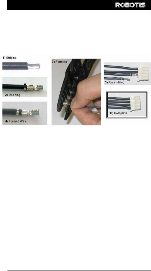
2-2 . Connector Assembly
Assemble the connectors as shown below. Attach the wires to the terminals using the correct crimping tool. If you do not have access to a crimping tool, solder the terminals to the wires to ensure that they do not become loose during operation.
5
DYNAMIXEL AX-12
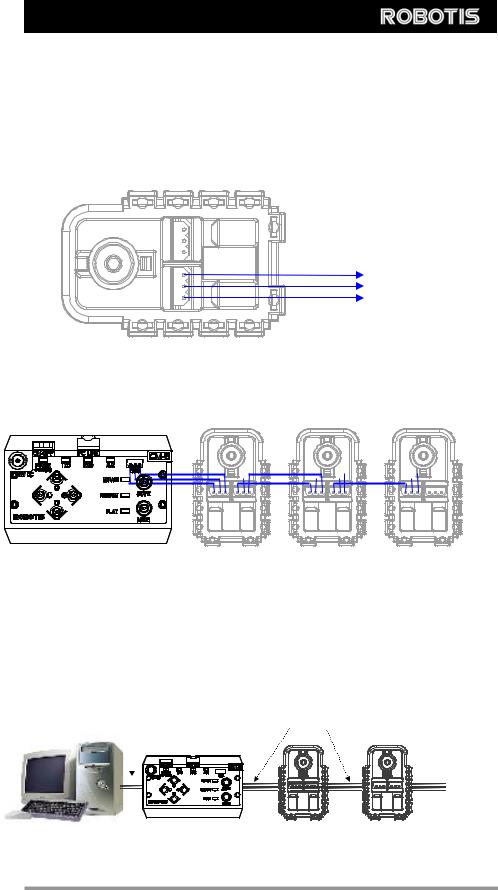
2-3. Dynamixel Wiring
Pin Assignment The connector pin assignments are as the following. The two connectors on the Dynamixel are connected pin to pin, thus the AX-12 can be operated with only one connector attached.
 PIN1: GND
 PIN2: VDD
 PIN3: Data
PIN1: GND
PIN2: VDD
PIN3: Data
Wiring |
Connect the AX-2 actuators pin to pin as shown below. Many AX-12 actuators can be |
||||||
|
controlled with a single bus in this manner. |
||||||
|
|
|
|
|
|
|
|
|
|
|
|
|
|
|
|
Control Box “CM-5”
Main Controller To operate the Dynamixel actuators, the main controller must support TTL level half duplex UART. A proprietary controller can be used, but the use of the Dynamixel controller CM-5 is recommended.
PC LINK |
A PC can be used to control the Dynamixel via the CM-5 controller. |
TTL
RS232 Level
Level
PC |
CM-5 |
Dynamixels |
6
DYNAMIXEL |
AX-12 |
bioloid |
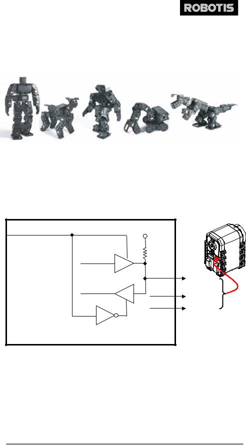
A robot can be built using only the CM-5 controller and a number of AX-12 actuators. An |
|
edutainment robotic kit named “Bioloid” is available which is based on the CM-5 |
|
controller and the AX-12 actuators. |
An example of a robot built with Bioloid
For details, please refer to the Bioloid manual.
Connection to UART To control the Dynamixel actuators, the main controller needs to convert its UART signals to the half duplex type. The recommended circuit diagram for this is shown below.
DIRECTION_PORT |
5V |
74HC126 |
10K |
|
TXD |
|
|
|
|
|
74HC126 |
DATA |
DATA(PIN3) |
|
|
|
RXD |
9.6V |
VDD(PIN2) |
|
||
|
GND |
GND(PIN1) |
|
|
74HC04
CM-5 internal circuit (HALF DUPLEX UART)
The power is supplied to the Dynamixel actuator from the main controller through Pin 1 and Pin 2 of the Molex3P connector. (The circuit shown above is presented only to explain the use of half duplex UART. The CM-5 controller already has the above circuitry built in, thus the Dynamixel actuators can be directly connected to it)
The direction of data signals on the TTL level TxD and RxD depends on the DIRECTION_PORT level as the following.
7
DYNAMIXEL AX-12
•When the DIRECTION_PORT level is High: the signal TxD is output as Data
•When the DIRECTION_PORT level is Low: the signal Data is input as RxD
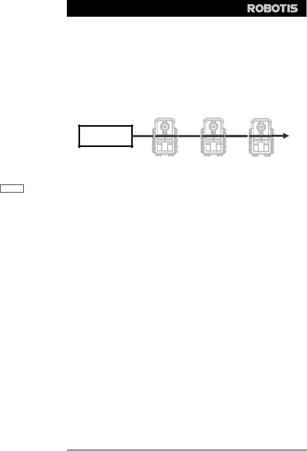
Half Duplex UART A multi-drop method of connecting multiple Dynamixel actuators to a single node is possible by using the half duplex UART. Thus a protocol that does not allow multiple transmissions at the same time should be maintained when controlling the Dynamixel actuators.
|
Main |
|
Controller |
|
[Multi Drop Link] |
Caution |
Please ensure that the pin assignments are correct when connecting the Dynamixel |
|
actuators. Check the current consumption when powering on. The current consumption |
|
of a single Dynamixel actuator unit in standby mode should be no larger than 50mA |
Connection Status Verification
When power is applied to the Dynamixel actuator, the LED blinks twice to confirm its connection.
Inspection |
If the above operation was not successful, then check the connector pin assignment and |
|
the voltage/current limit of the power supply. |
8
DYNAMIXEL AX-12
|
3. Communication Protocol |
3-1. Communication Overview |
|
Packet |
The main controller communicates with the Dynamixel units by sending and receiving |
|
data packets. There are two types of packets; the “Instruction Packet” (sent from the |
main controller to the Dynamixel actuators) and the “Status Packet” (sent from the Dynamixel actuators to the main controller.)
|
Instruction Packet |
|
Main |
||
|
||
Controller |
Status Packet |
|
|
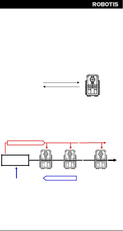
Communication For the system connection below, if the main controller sends an instruction packet with the ID set to N, only the Dynamixel unit with this ID value will return its respective status packet and perform the required instruction.
Instruction Packet(ID=N)
Main
Controller
ID=0 |
ID=1 |
ID=N |
||
|
Status Packet(ID=N) |
|
|
|
|
|
|
||
|
|
|
||
Unique ID |
If multiple Dynamixel units have the same ID value, multiple packets sent |
|
simultaneously collide, resulting in communication problems. Thus, it is imperative that |
|
no Dynamixel units share the same ID in a network node. |
Protocol |
The Dynamixel actuators communicate through asynchronous serial communication |
|
with 8 bit, 1 stop bit and no parity. |
9
DYNAMIXEL AX-12
3-2. Instruction Packet
|
|
|
|
|
|
|
|
The Instruction Packet is the packet sent by the main controller to the Dynamixel units |
|||||||||||||
|
|
|
|
|
|
|
|
to send commands. The structure of the Instruction Packet is as the following. |
|||||||||||||
Instruction Packet |
|
|
|
ID |
|
|
|
|
|
|
|
|
|
|
|||||||
OXFF |
0XFF |
LENGTH |
INSTRUCTION |
PARAMETER1 |
…PARAMETER N |
CHECK SUM |
|||||||||||||||
|
|
|
|
|
|
|
|
The meanings of each packet byte definition are as the following. |
|||||||||||||
|
|
|
|
|
|
|
|
The two 0XFF bytes indicate the start of an incoming packet. |
|||||||||||||
0XFF |
|
0XFF |
|
|
|
|
|||||||||||||||
ID |
The unique ID of a Dynamixel unit. There are 254 available ID values, ranging from |
||||||||||||||||||||
|
|
|
|
|
|
|
|
0X00 to 0XFD. |
|||||||||||||
Broadcasting ID |
ID 0XFE is the Broadcasting ID which indicates all of the connected Dynamixel units. |
||||||||||||||||||||
|
|
|
|
|
|
|
|
Packets sent with this ID apply to all Dynamixel units on the network. Thus packets sent |
|||||||||||||
|
|
|
|
|
|
|
|
with a broadcasting ID will not return any status packets. |
|||||||||||||
|
|
|
|
|
The length of the packet where its value is “Number of parameters (N) + 2” |
||||||||||||||||
LENGTH |
|
|
|
|
|||||||||||||||||
|
|
|
|
The instruction for the Dynamixel actuator to perform. |
|||||||||||||||||
INSTRUCTION |
|
|
|||||||||||||||||||
|
|
|
Used if there is additional information needed to be sent other than the instruction itself. |
||||||||||||||||||
PARAMETER0…N |
|
||||||||||||||||||||
|
|
The computation method for the ‘Check Sum’ is as the following. |
|||||||||||||||||||
CHECK SUM |
|
||||||||||||||||||||
|
|
|
|
|
|
|
|
Check Sum = ~ (ID + Length + Instruction + Parameter1 + ... Parameter N) |
|||||||||||||
|
|
|
|
|
|
|
|
If the calculated value is larger than 255, the lower byte is defined as the checksum |
|||||||||||||
|
|
|
|
|
|
|
|
value. |
|||||||||||||
|
|
|
|
|
|
|
|
~ represents the NOT logic operation. |
|||||||||||||
3-3. Status Packet(Return Packet)
The Status Packet is the response packet from the Dynamixel units to the Main Controller after receiving an instruction packet. The structure of the status packet is as the following.
OXFF
 0XFF
0XFF
 ID
ID
 LENGTH
 ERROR
ERROR
 PARAMETER1
 PARAMETER2…PARAMETER N
 CHECK SUM
10

DYNAMIXEL AX-12
|
|
|
|
|
|
|
|
The meanings of each packet byte definition are as the following. |
|
|
|
|||
|
|
|
|
|
|
|
|
The two 0XFF bytes indicate the start of the packet. |
|
|
|
|
||
0XFF |
|
0XFF |
|
|
|
|
|
|
|
|||||
ID |
The unique ID of the Dynamixel unit returning the packet. The initial value is set to 1. |
|
||||||||||||
|
|
|
|
|
The length of the packet where its value is “Number of parameters (N) + 2” |
|
|
|||||||
LENGTH |
|
|
|
|
|
|||||||||
|
|
|
|
The byte representing errors sent from the Dynamixel unit. The meaning of each bit is |
||||||||||
ERROR |
|
|
|
|||||||||||
|
|
|
|
|
|
|
|
as the following. |
|
|
|
|
|
|
|
|
|
|
|
|
|
|
|
|
|
|
|
|
|
|
|
|
|
|
|
|
|
Bit |
Name |
|
Details |
|
|
|
|
|
|
|
|
|
|
|
|
|
|
|
|
|
|
|
|
|
|
|
|
|
|
Bit 7 |
0 |
|
- |
|
|
|
|
|
|
|
|
|
|
|
|
|
|
|
|
||
|
|
|
|
|
|
|
|
Bit 6 |
Instruction Error |
Set to 1 if an undefined instruction is sent or |
an |
action |
||
|
|
|
|
|
|
|
|
instruction is sent without a Reg_Write instruction. |
|
|
||||
|
|
|
|
|
|
|
|
|
|
|
|
|||
|
|
|
|
|
|
|
|
|
|
|
|
|||
|
|
|
|
|
|
|
|
Bit 5 |
Overload Error |
Set to 1 if the specified maximum torque can't |
control the |
|||
|
|
|
|
|
|
|
|
applied load. |
|
|
|
|
||
|
|
|
|
|
|
|
|
|
|
|
|
|
|
|
|
|
|
|
|
|
|
|
|
|
|
||||
|
|
|
|
|
|
|
|
Bit 4 |
Checksum Error |
Set to 1 if the checksum of the instruction packet is incorrect. |
||||
|
|
|
|
|
|
|
|
|
|
|
||||
|
|
|
|
|
|
|
|
Bit 3 |
Range Error |
Set to 1 if the instruction sent is out of the defined range. |
||||
|
|
|
|
|
|
|
|
|
|
|
||||
|
|
|
|
|
|
|
|
|
Overheating |
Set to 1 if the internal temperature of the Dynamixel unit is |
||||
|
|
|
|
|
|
|
|
Bit 2 |
above the operating |
temperature |
range as defined |
in the |
||
|
|
|
|
|
|
|
|
Error |
||||||
|
|
|
|
|
|
|
|
|
control table. |
|
|
|
|
|
|
|
|
|
|
|
|
|
|
|
|
|
|
|
|
|
|
|
|
|
|
|
|
|
|
|
|
|
|
|
|
|
|
|
|
|
|
|
|
Angle Limit |
Set as 1 if the Goal |
Position is |
set outside of |
the |
range |
|
|
|
|
|
|
|
|
Bit 1 |
between CW Angle Limit and CCW Angle |
|
|
|||
|
|
|
|
|
|
|
|
Error |
|
|
||||
|
|
|
|
|
|
|
|
|
Limit. |
|
|
|
|
|
|
|
|
|
|
|
|
|
|
|
|
|
|
|
|
|
|
|
|
|
|
|
|
|
|
|
||||
|
|
|
|
|
|
|
|
Bit 0 |
Input Voltage |
Set to 1 if the voltage is out of the operating voltage range as |
||||
|
|
|
|
|
|
|
|
Error |
defined in the control table. |
|
|
|
||
|
|
|
|
|
|
|
|
|
|
|
|
|||
|
|
|
|
|
|
|
|
|
|
|||||
|
|
|
Used if additional information is needed. |
|
|
|
|
|||||||
PARAMETER0…N |
|
|
|
|
|
|||||||||
|
|
The computation method for the ‘Check Sum’ is as the following. |
|
|
|
|||||||||
CHECK SUM |
|
|
|
|
||||||||||
|
|
|
|
|
|
|
|
Check Sum = ~ (ID + Length + Instruction + Parameter1 + ... Parameter N) |
|
|
||||
If the calculated value is larger than 255, the lower byte is defined as the checksum value. ~ represents the NOT logic operation.
11
 Loading...