

Page 1
Page 2

2
AXIS 200 User’s Manual
Safety Notices
Please observe all safety markings and instructions when
using this product.
Caution! -
product.
Important -
impair operation.
Do not proceed any of the above notices until you have fully
understood the implications.
potential hazard that can damage the
potential hazard that can seriously
Legal Considerations
Camera surveillance can be prohibited by laws that vary
from country to country. Check out the laws in your
country before using the AXIS 200 for surveillance.
Electromagnetic Compatibility (EMC)
USA -
radio frequency energy and if not installed and used in
accordance with the instruction manual, may cause
interference to radio communications. It has been tested
and found to comply with the limits for a Class A
computing device pursuant to Subpart B of Part 15 of FCC
rules, which are designed to provide reasonable protection
against such interference when operated in a commercial
environment. Operation of this equipment in a residential
area is likely to cause interference in which case the user at
his/her own expense will be required to take whatever
measures may be required to correct the interference.
Shielded cables should be used with this unit to ensure
compliance with the Class A limits.
This equipment generates, uses, and can radiate
any kind with regard to the material contained within this
document, including, but not limited to, the implied warranties of
merchantability and fitness for a particular purpose. Axis
Communications shall not be liable nor responsible for incidental
or consequential damages in connection with the furnishing,
performance or use of this material.
Year 2000 Compliance
Axis Communications warrants that the AXIS 200 is year 2000
compliant.
Axis’ Trademarks
ThinServer
Trademark Acknowledgments
Acrobat, Adobe, Apple, Chimera, Ethernet, IBM, Internet,
Internet Explorer, LAN Manager, LAN Server, Macintosh,
Microsoft, NCSA Mosaic, Netscape Navigator, Novell NetWare,
Oracle Power Browser, OS/2, UNIX, Windows, WWW, are
registered trademarks of the respective holders.
AXIS 200 User’s Manual
Revision 1.6
Part No: 14978
Dated: October 1998
Copyright © Axis Communications AB,
1996 - 1998
Europe -
requirements for radiated emission according to limit B of
EN55022/1994, and the requirements for immunity
according to EN50082-1/1992 residential, commercial, and
light industry (Compliance is not valid for unshielded
network and printer cables).
This digital equipment fulfils the
Liability
Every care has been taken in the preparation of this manual;
if you detect any inaccuracies or omissions, please inform us
at an address which can be found in the last appendix of the
manual. Axis Communications cannot be held responsible
for any technical or typographical errors and reserves the
right to make changes to the product and manuals without
prior notice. Axis Communications makes no warranty of
Page 3

AXIS 200 User’s Manual Preface
Preface
Thank you for purchasing the AXIS 200 Network Camera Server. This product has been
developed to connect your cameras anywhere in your network, allowing all users to take high
quality snapshot pictures around the globe over Internet and intranet networks.
About This Manual
The manual provides introductory information as well as detailed instructions on how to set up
and manage the AXIS 200 in various network environments. It is intended for everyone involved
in installing and managing the AXIS 200. To fully benefit from the manual, you should be
familiar with basic networking principles.
This manual applies to the AXIS 200, with software release 1.31.
1
About Axis
Axis Communications is dedicated to providing innovative solutions for network-connected
computer peripherals. Since the start in 1984, Axis has been one of the fastest growing companies
in the market and is now a leader in its field.
ThinServer™ Technology
enables them to act as intelligent file server independent ThinServer™ devices. A ThinServer™
device is a network server which includes “thin” embedded server software capable of
simultaneous multiprotocol communication, scalable RISC hardware and a built-in Web server
which allows easy access and management via any standard Web browser. The ThinServer™
technology makes it possible to connect any electronic device to the network, thus providing
“Access to everything”.
Today, Axis Communications is offering the ThinServer™ technology as well as six major
ThinServer™ product lines consisting of:
Network Print Servers
resources in your network. They connect to any standard printer, featuring high performance,
simple management and easy upgrading across the network. The print servers are available in
Ethernet, Fast Ethernet and Token Ring versions.
Being the core of all Axis’ products, the ThinServer™ technology
offer you a powerful and cost-efficient method for sharing printer
IBM Mainframe and S/3x - AS/400 Print Servers and Protocol Converters
wide range of LAN, coax and twinax attached print servers for the IBM host environment. By
emulating IBM devices, these servers provide conversion of the IPDS, SCS and 3270DS data
streams to the major ASCII printer languages.
includes a
Page 4

2
Preface AXIS 200 User’s Manual
Network Attached Optical Media Servers
provide you with a flexible and cost-efficient
solution for sharing CD-ROMs, DVD-ROMs and other optical media across the network. They
are available in Ethernet, Fast Ethernet and Token Ring versions.
Network Attached Storage Servers
offer network connectivity for re-writable media such as
hard disks and Iomega Jaz cartridges, which, via the storage server, can be backed up on DAT
tapes. They are only available in Ethernet versions.
Network Camera Servers
provide live images using standard Internet technology, thus
enabling access to live cameras via any standard Web browser. They offer a perfect solution for
remote surveillance over the Internet and their sharp images can bring life into any web site.
These servers support Ethernet as well as PSTN and GSM phone lines.
Network Scan Servers
enable easy distribution of paper-based information across workgroups
and the enterprise. By sending the scanned documents to your destination via the
Internet/intranet, you will reduce your faxing/mailing costs, as well as save time, thus improving
your organization efficiency.
Support Services
Should you require any technical assistance, please contact your local dealer. If your questions
cannot be answered immediately, your local dealer will forward your queries through the
appropriate channels to ensure you a rapid response.
WWW: http://www.axis.com
FTP server: ftp://ftp.axis.com/pub/axis
Support
e-mail address:
tech-sup@axis.com
If you are connected to Internet, you can find online
manuals, technical support, firmware updates,
application software, company information, on any of
the addresses listed to the left.
Page 5

AXIS 200 User’s Manual Table of Contents
Table of Contents
Section 1 Introduction . . . . . . . . . . . . . . . . . . . . . . . . . . . . . . . . . . . . . . . . . . . . . . . . . . 5
The AXIS 200 Network Camera . . . . . . . . . . . . . . . . . . . . . . . . . . . . . . 5
Features and Benefits . . . . . . . . . . . . . . . . . . . . . . . . . . . . . . . . . . . . . . . 6
Section 2 Installing the AXIS 200 . . . . . . . . . . . . . . . . . . . . . . . . . . . . . . . . . . . . . . . . . . 9
Installation Summary . . . . . . . . . . . . . . . . . . . . . . . . . . . . . . . . . . . . . . . . 9
Stage 1. Unpacking and Checking the Hardware . . . . . . . . . . . . . . . . . 10
Stage 2. Identifying the Connectors and Indicators . . . . . . . . . . . . . . . 11
Stage 3. Connecting the AXIS 200 to your Network . . . . . . . . . . . . . 13
Stage 4. Assigning an Internet Address and Host Name . . . . . . . . . . 13
Stage 5. Testing the AXIS 200 . . . . . . . . . . . . . . . . . . . . . . . . . . . . . . . 14
Stage 6. Adjusting the Focus . . . . . . . . . . . . . . . . . . . . . . . . . . . . . . . . . 16
3
Section 3 Assigning an Internet Address . . . . . . . . . . . . . . . . . . . . . . . . . . . . . . . . . . . 17
Downloading the Internet Address . . . . . . . . . . . . . . . . . . . . . . . . . . . 17
Section 4 Configuring the AXIS 200 . . . . . . . . . . . . . . . . . . . . . . . . . . . . . . . . . . . . . . . 23
Configuring using a Web browser. . . . . . . . . . . . . . . . . . . . . . . . . . . . . 24
White Balance . . . . . . . . . . . . . . . . . . . . . . . . . . . . . . . . . . . . . . . . . . . . 30
Configuring using FTP . . . . . . . . . . . . . . . . . . . . . . . . . . . . . . . . . . . . . . 32
Section 5 Using the AXIS 200 . . . . . . . . . . . . . . . . . . . . . . . . . . . . . . . . . . . . . . . . . . . . 33
Snapshots . . . . . . . . . . . . . . . . . . . . . . . . . . . . . . . . . . . . . . . . . . . . . . . . 34
Automatic Picture Updates . . . . . . . . . . . . . . . . . . . . . . . . . . . . . . . . . . 37
External Web Sites . . . . . . . . . . . . . . . . . . . . . . . . . . . . . . . . . . . . . . . . 38
CRON Script . . . . . . . . . . . . . . . . . . . . . . . . . . . . . . . . . . . . . . . . . . . . . 39
Common Gateway Interface (CGI). . . . . . . . . . . . . . . . . . . . . . . . . . . . 47
Point to Point Protocol (PPP) . . . . . . . . . . . . . . . . . . . . . . . . . . . . . . . . 49
Zmodem . . . . . . . . . . . . . . . . . . . . . . . . . . . . . . . . . . . . . . . . . . . . . . . . 52
Appendix A Troubleshooting . . . . . . . . . . . . . . . . . . . . . . . . . . . . . . . . . . . . . . . . . . . . . . 55
The Log File . . . . . . . . . . . . . . . . . . . . . . . . . . . . . . . . . . . . . . . . . . . . . . 55
Symptoms, Possible Causes and Remedial Actions . . . . . . . . . . . . . . . 57
Appendix B The Parameter List . . . . . . . . . . . . . . . . . . . . . . . . . . . . . . . . . . . . . . . . . . . 61
The Config File . . . . . . . . . . . . . . . . . . . . . . . . . . . . . . . . . . . . . . . . . . . 61
Page 6

4
Table of Contents
AXIS 200 User’s Manual
Factory Default Settings . . . . . . . . . . . . . . . . . . . . . . . . . . . . . . . . . . . . 64
Appendix C Updating the Software . . . . . . . . . . . . . . . . . . . . . . . . . . . . . . . . . . . . . . . . . 65
Obtaining Updated Software . . . . . . . . . . . . . . . . . . . . . . . . . . . . . . . . 65
Upgrading the Software . . . . . . . . . . . . . . . . . . . . . . . . . . . . . . . . . . . . 66
Appendix D Technical Specifications . . . . . . . . . . . . . . . . . . . . . . . . . . . . . . . . . . . . . . . . . 69
Appendix E The Auxiliary IO Port . . . . . . . . . . . . . . . . . . . . . . . . . . . . . . . . . . . . . . . . . . 73
Physical connection . . . . . . . . . . . . . . . . . . . . . . . . . . . . . . . . . . . . . . . . 73
Controlling and Monitoring . . . . . . . . . . . . . . . . . . . . . . . . . . . . . . . . . 74
Appendix F The RS232 Serial Port . . . . . . . . . . . . . . . . . . . . . . . . . . . . . . . . . . . . . . . . . . 77
Physical connector . . . . . . . . . . . . . . . . . . . . . . . . . . . . . . . . . . . . . . . . 77
Setting Up the AXIS 200 Modem Server . . . . . . . . . . . . . . . . . . . . . . . 78
Appendix G Camera Applications . . . . . . . . . . . . . . . . . . . . . . . . . . . . . . . . . . . . . . . . . . . 87
Appendix H CRON Script Command Reference . . . . . . . . . . . . . . . . . . . . . . . . . . . . . . . 89
Script Format . . . . . . . . . . . . . . . . . . . . . . . . . . . . . . . . . . . . . . . . . . . . 89
Commands . . . . . . . . . . . . . . . . . . . . . . . . . . . . . . . . . . . . . . . . . . . . . . 90
Page 7

AXIS 200 User’s Manual Section 1: Introduction
Section 1 Introduction
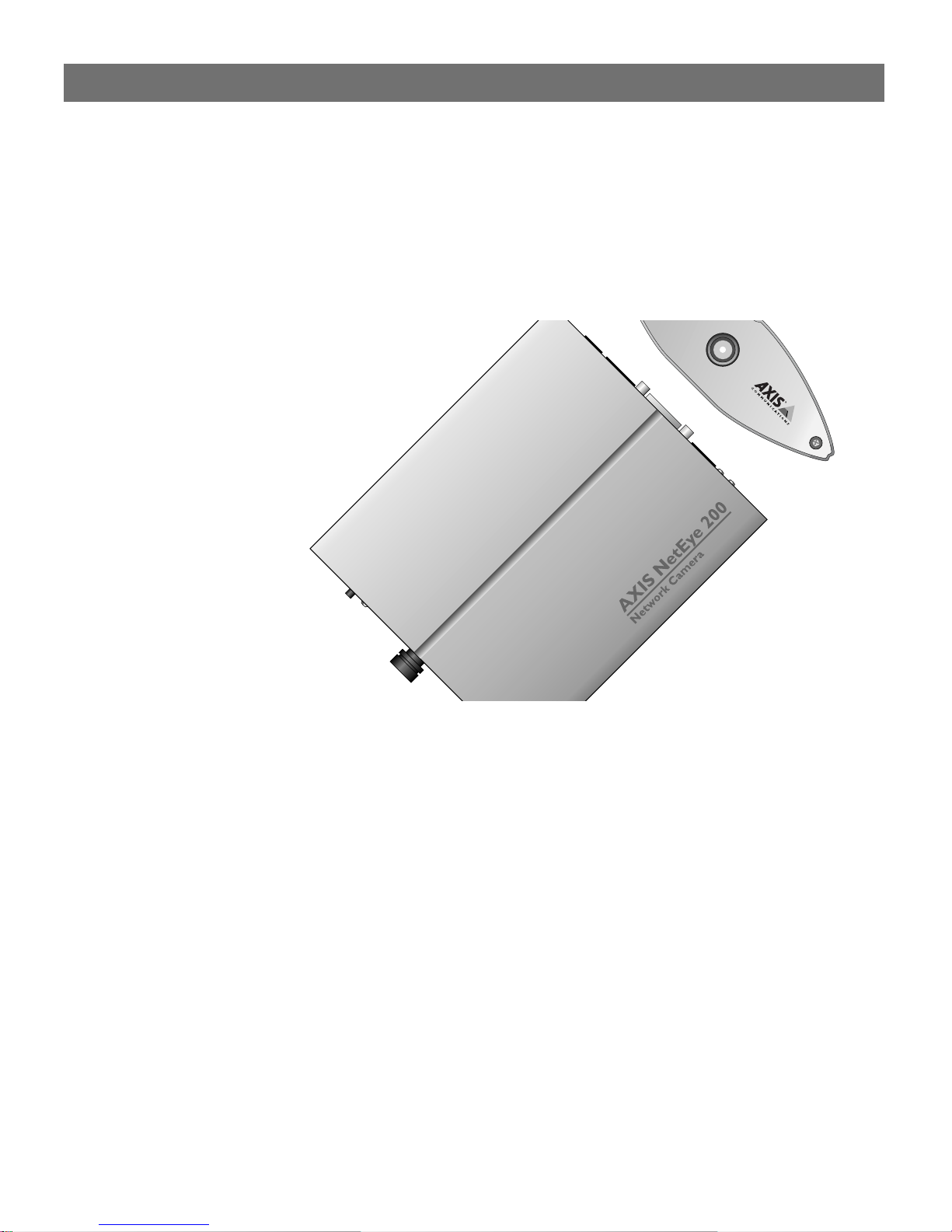
The AXIS 200 Network Camera
The AXIS 200 Network Camera is a digital snapshot camera with a
built-in Web server. Connecting directly to Ethernet networks, it
provides a source for live color pictures over the Internet.
5
In the past, network imaging solutions have required cumbersome,
complicated systems involving PCs or workstations with specific video
cabling. The AXIS 200 eliminates the cost, management and
maintenance issues commonly associated with those types of solutions.
Technically, the AXIS 200 is a microprocessor-based device that
includes:
•
•
•
•
The AXIS 200 Network Camera
A digital color camera
RISC-based hardware for image compression
Standalone Web server functionality
Physical Ethernet connection
Page 8
6
Section 1: Introduction
Features and Benefits
AXIS 200 User’s Manual
Easy Installation
Cost-effective
Operating
Environments
Connecting the AXIS 200 to the network is easy. It does not require
the use of a PC frame grabber card or interaction with any other
server. No additional software or hardware is needed. You can actually
install it in a single minute - all you need to do is assign a valid
Internet address.
With all necessary features included, the AXIS 200 provides a reliable
and low cost alternative for publication of pictures on the network.
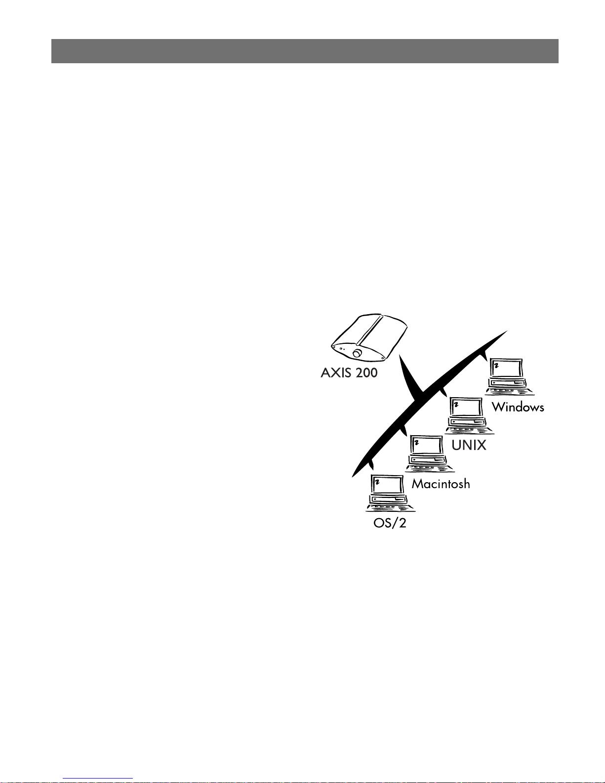
The AXIS 200 supports
TCP/IP and Internetrelated protocols. It can
therefore be used in
mixed operating system
environments such as
Windows, Macintosh,
UNIX and OS/2.
Standard Image
Format
Using a standard Web
browser, the AXIS 200
can be configured and
managed directly from
its own Web pages.
The AXIS 200 also supports FTP so that snapshots can be taken and
saved locally.
The AXIS 200 generates pictures in standard JPEG format which
means that users can take and view pictures over the network using
any standard Web browser. Pictures taken by the AXIS 200 can be
displayed in your Web pages by creating HTML links.
The AXIS 200 provides high-quality snapshot pictures for any
Internet/intranet client that cares to visit it. Primarily designed to
produce a ‘live’ snapshot for each occasion it is accessed, it can also
broadcast recently generated pictures upon request.
Page 9

AXIS 200 User’s Manual Section 1: Introduction
7
Fast JPEG
Compression
External Device
Connection
Security
Web Forum
discussions
The AXIS 200 has hardware support for the JPEG compression as well
as a 32-bit high speed RISC CPU. This results in fast JPEG
compression. The AXIS 200 provides JPEG images directly, without
the need for manual conversion between image formats. A full size
JPEG image is compressed in less than one second.
The auxiliary input makes it possible to control the AXIS 200 from
external relays. This means that external devices like door-openers,
external switches, etc. can trigger the camera.
The AXIS 200 is a self-contained web server. This means that the
server is secured like any other Internet host. It is up to the Network
Administrator to decide whether individuals, groups, the whole
company or the whole world may access your camera server. Normally
this is done in your company's Internet firewall.
Axis Communications will be running a web forum for ideas and
suggestion notes for possible camera applications. Axis will also
maintain a link collection where you can insert your own link to your
application and keep lists of application notes, FAQ:s and other
related information.
Page 10

8
Section 1: Introduction
AXIS 200 User’s Manual
Page 11
AXIS 200 User’s Manual Section 2: Installing the AXIS 200
Section 2 Installing the AXIS 200
This section provides a brief description of the unit connectors and
indicators, and describes the AXIS 200 installation procedures.
9
Installation Summary
The AXIS 200 is installed in these stages:
Stage 1. Unpacking and Checking the Hardware.
Stage 2. Identifying the Connectors and Indicators
Stage 3. Connecting the AXIS 200 to your Network
Stage 4. Assigning an Internet Address and Host Name
Stage 5. Testing the AXIS 200
Stage 6. Adjusting the Focus
Page 12

10
Section 2: Installing the AXIS 200
AXIS 200 User’s Manual
Stage 1. Unpacking and Checking the Hardware
Unpack and check all the items against the check list below. Contact
your dealer if anything is missing or damaged. All packing material is
recyclable. The AXIS 200 hardware pack contains:
AXIS 200 Network Camera, part no: 0064-1
AXIS 200 Quick Installation Guide, part no: 15107
AXIS 200 Tripod
Product Brochure, part no: 14412
Power supply. Part numbers vary according to country, as
described in this table:
Country Part Number
Europe 14233
UK 14234
Australia 14255
USA 14253
Japan 14254
Page 13
AXIS 200 User’s Manual Section 2: Installing the AXIS 200
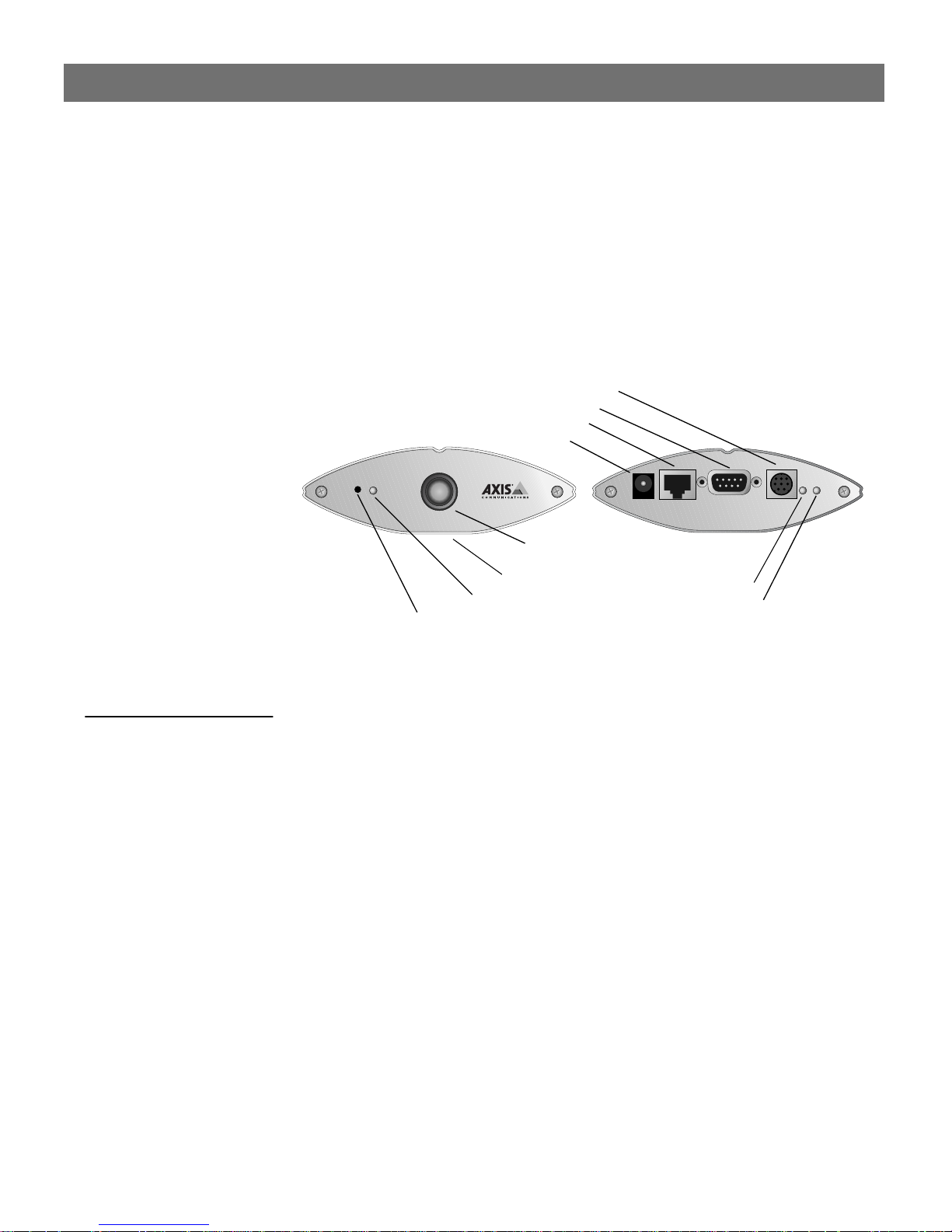
Stage 2. Identifying the Connectors and Indicators
Please read the following information to familiarize yourself with the
AXIS 200, making particular note of where the connectors and
indicators are located. This information provide a useful reference
when performing the remaining stages of the installation.
Auxiliary I/O connector
RS232 serial connector
Ethernet 10baseT connector
Power supply connector
11
Connectors
Auxiliary I/O
Connector
RS232 Serial
Connector
Camera lens
(with rotational focus control)
Serial number
Snapshot indicator
Control button
Front view
Power indicator
Network indicator
Rear view
A Mini-DIN 8-pole external connector for auxiliary connection to the
AXIS 200. The functionality of this connector is fully discussed in
Appendix E - The Auxiliary IO Port.
A 9 pin D-sub connector provides the physical RS232 serial interface
to a modem server within the AXIS 200. This connector is discussed
in detail in Appendix F - The RS232 Serial Port.
Ethernet 10baseT
Connector
Power Supply
10baseT (RJ-45) twisted pair Ethernet connector for connection to
the network.
Jack socket for connection of AXIS 200 power supply.
Connector
Page 14

12
Section 2: Installing the AXIS 200
AXIS 200 User’s Manual
Caution!
Indicators
Snapshot Indicator
Power Indicator
Network Indicator
Camera Lens
The power supply delivered with your AXIS 200 is country specific.
Please check that the type of power supply you are using is correct
against the checklist on page 10.
This indicator will flash on every occasion the AXIS 200 takes a
snapshot.
This is normally lit while power is applied. If it is not lit, or it flashes,
there is problem with the AXIS 200 power supply.
This flashes to indicate network activity.
Wide angle lens with rotational-focus control. Refer to Appendix D -
Technical Specifications for complete specification.
Serial Number
Control Button
This is located on the underside label of the AXIS 200. Please note
that the serial number of your AXIS 200 is identical to the Ethernet
address of the unit.
This is used for multiple purposes, e.g. restoring the factory default
settings, adjusting the White balance, triggering CRON scripts. Refer
to the appropriate sections of the manuals.
Page 15

AXIS 200 User’s Manual Section 2: Installing the AXIS 200
Stage 3. Connecting the AXIS 200 to your Network
To connect your AXIS 200 to the network, follow the step-by-step
instructions below:
1. Note the serial number of your AXIS 200 for future reference
during the installation procedure. This is located on the underside
label of the AXIS 200. Please note that the serial number of your
AXIS 200 is identical to the Ethernet address of the unit.
2. Fasten the AXIS 200 to its tripod and position it appropriately for
your application.
13
Caution!
❏ Please note that the CCD (charged coupled device) within the
AXIS 200 can become permanently damaged if the camera lens is
exposed to too much direct sunlight! If your application demands
prolonged exposure to sunlight, you should consider the purchase
of a visor. Refer to the following link for further information:
http://www.axis.com/products/camera_servers/applic/housing.
htm
3. Connect your AXIS 200 to the network using an Ethernet 10baseT
connector.
4. Connect the power supply to the AXIS 200.
5. Check that the Power indicator is constantly lit.
Stage 4. Assigning an Internet Address and Host Name
Assign and download an Internet address and Host name for your
AXIS 200. Refer to Section 3 - Assigning an Internet Address.
Page 16
14
Section 2: Installing the AXIS 200
Stage 5. Testing the AXIS 200
You are now ready to test the connection between your AXIS 200 and
the network.
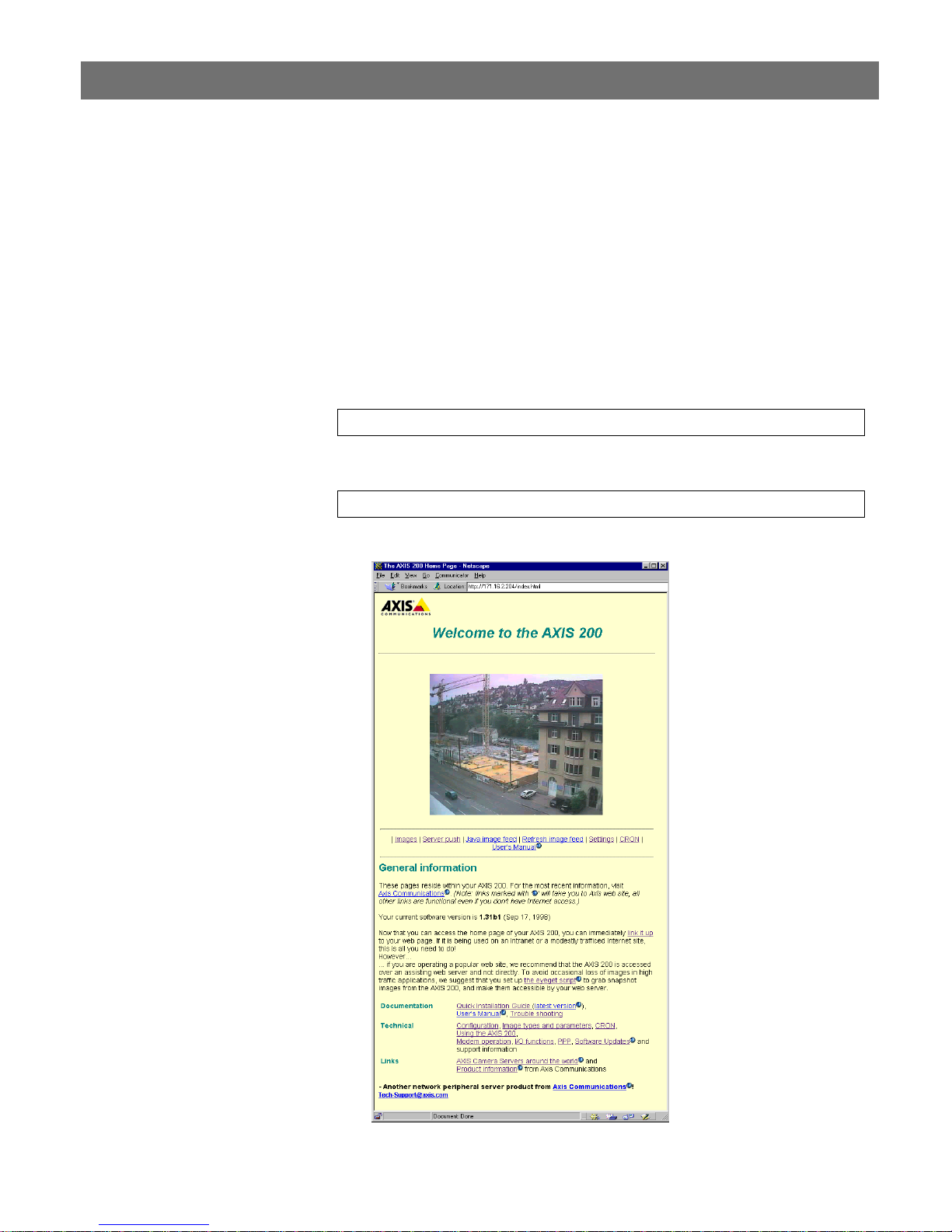
1. Start your Web browser.
2. Enter the name or Internet address of the AXIS 200 in the
location/address field:
http://cameraname/
or:
http://192.168.3.191/
AXIS 200 User’s Manual
The Home Page of your AXIS 200 appears.
Page 17

AXIS 200 User’s Manual Section 2: Installing the AXIS 200
3. To further test your AXIS 200, take some more pictures. You can
do this by simply reloading your Web browser.
15
Notes:
❏ Server push and other automatic updating functions are described
in Automatic Picture Updates, on page 37.
❏ Web pages are kept locally for fast browsing and in some instances
your AXIS 200 may display a cached image, as opposed to a newly
taken snapshot. In these circumstances, we recommend that you
reload your Web browser.
Page 18

16
Section 2: Installing the AXIS 200
Stage 6. Adjusting the Focus
The AXIS 200 has a lens with rotational focus control. To obtain a
sharp picture, adjust the focus of your AXIS 200 by carefully turning
the lens. A white spot on the lens assembly indicates the approximate
focus position for the unit, when adjusted to a 12
o’clock position.
You can test the results of the adjustments you have made by taking
some new pictures. To do this, simply reload your Web browser. If
you are using Netscape Navigator, you can simultaneously monitor
the changes to focus by clicking on the
Home Page.
AXIS 200 User’s Manual
Server push
link within the
Notes:
❏ To correctly set the focus, you might need to turn the lens one or
two full turns either clockwise or anticlockwise from the 12
o’clock position.
❏ The lens assembly rotates on a conventional screw fitting and may
be completely removed if taken to the end of its thread. You
should not normally require to remove the lens, but should you
have cause to do so, take care not to let any debris enter the lens as
this will adversely effect the quality of your picture snapshots.
White dot
(focus position)
Front view
Camera lens
(with rotational focus control)
The installation is now complete and pictures may now be included
into your own applications.
Note:
❏ To avoid the occasional loss of snapshot images, we suggest that
you use the CRON script facility described in “CRON Script” on
page 39.
Page 19

AXIS 200 User’s Manual Section 3: Assigning an Internet Address
Section 3 Assigning an Internet Address
To enable access to your AXIS 200, you must first assign it an
appropriate Internet address.
This section describes how to assign and download an Internet address
for your AXIS 200.
Downloading the Internet Address
You can set the Internet address of the AXIS 200 in three different
ways, using either ARP, RARP or BOOTP. All methods are enabled
by default. The main characteristics of each of these methods are
described below:
17
ARP
RARP
BOOTP
ARP is available in Windows 95, Windows NT, UNIX and OS/2. It
requires the Internet address for each new device to be downloaded
individually. It is not appropriate to use this method over routers.
RARP is available in UNIX. It downloads the Internet address to each
device automatically. It requires a RARP daemon on your system, and
operates within a single network segment only.
BOOTP is available in UNIX and is similar to RARP, although it can
operate on the entire network. It requires a BOOTP daemon on your
system. A request made to an active BOOTP or RARP daemon
initiates a search of the Ethernet address table (RARP daemon), or
boot table (BOOTP daemon) for an entry matching the unit’s
Ethernet address. If a matching entry is found, the daemon then
downloads the Internet address to the device.
Page 20

18
Section 3: Assigning an Internet Address
AXIS 200 User’s Manual
Before you begin
Internet Address
System Privileges
Ethernet Address
Important!
Make sure the AXIS 200 is powered up and attached to the network.
Acquire an unused Internet address from your Network
Administrator.
You will require root privileges on your UNIX system and
administrator privileges on the Windows NT servers.
Depending on the method you are using, you will need to know the
Ethernet address of your AXIS 200. The Ethernet address is based
upon the serial number found on the underside label of the unit.
❏ Do not use the default or example Internet address when
installing your AXIS 200. Always consult your Network
Administrator before assigning an Internet address.
Mapping a Host Name
to the Internet
Address
Note:
If you are using host names, you can map a unique host name to the
acquired Internet address. Refer to your system manuals or to your
Network Administrator for instructions on how to perform the name
mapping on your particular system.
❏ If the host name has not been included in the system host table,
you can still perform the following instructions on how to
download the Internet address. In this case, simply replace the
host name entry with the Internet address wherever required.
Page 21

AXIS 200 User’s Manual Section 3: Assigning an Internet Address
19
Procedures
Using ARP in
Windows 95 and
Windows NT
Choose one of the following methods to download the Internet
address to your AXIS 200.
Follow these instructions to download the Internet address and verify
the communication.
Start a DOS window and type the following commands:
arp -s <Internet address> <Ethernet address>
ping <Internet address>
Example:
arp -s 192.168.3.191 00-40-8c-10-00-86
ping 192.168.3.191
The host will return ‘
Reply from 192.168.3.191 ...
’ or some
similar message. This indicates that the address has been set and the
communication is established.
Important!
Note:
Windows 95 only: if the ARP table is empty, you must first ping an
existing unit on your network before setting the Internet address of
your AXIS 200. Type
arp -a
to display the ARP table.
Note that if your AXIS 200 unit is connected to the Windows 95
client via a hub, without network connection to other devices, you
must use the command
address> <client address>
arp -s <Internet address> <Ethernet
where
<client address>
is the
Internet address of your Windows 95 client.
command for the first time, you will
❏ When you execute the
ping
experience a significantly longer response time than usual.
Page 22
20
Section 3: Assigning an Internet Address
AXIS 200 User’s Manual
Using ARP in
UNIX and OS/2
Notes:
Follow these instructions to download the Internet address and verify
the communication.
Type the following commands:
arp -s <host name> <Ethernet address> temp
ping <host name>
Example:
arp -s cameraname 00:40:8c:10:00:86 temp
ping cameraname
The host will return ‘
cameraname is alive’,
or some similar
message to indicate that the address has been set and the
communication is established.
command for the first
❏ Please note that when you execute the
ping
time, you may experience a significantly longer response time
than is usual.
❏ The
arp -s
command may vary from system to system. Some
BSD-type systems expect the host name and Ethernet address in
reverse order, whereas IBM AIX systems require the additional
argument
arp -s ether <host name> 00:40:8c:10:00:86 temp
ether
. For example:
Page 23
AXIS 200 User’s Manual Section 3: Assigning an Internet Address
21
Using RARP in UNIX
Follow these steps to use the RARP method in UNIX:
1. Append the following line to your Ethernet address table. This is
typically performed using the command
<Ethernet address> <host name>
/etc/ethers
:
Example:
00:40:8c:10:00:86 cameraname
2. If necessary, update your host table and alias name databases as
described required by your system.
3. If it is not already running, start the rarp daemon. This is typically
performed using the command
rarpd -a
4. Restart the AXIS 200 to download the Internet address.
Page 24

22
Section 3: Assigning an Internet Address
AXIS 200 User’s Manual
Using BOOTP
in UNIX
Follow these steps to use the BOOTP method:
1. Append the following entry to your boot table. This is typically
performed using the command
<host name>:ht=<hardware type>:vm=<vendor
magic>:\
:ha=<hardware address>:ip=<Internet address>:\
:sm=<subnet mask>:gw=<gateway field>
/etc/bootptab
:
where:
ht
= ether
vm
= rfc1048
ha
= The Ethernet address of the AXIS 200
ip
= The Internet address of the AXIS 200
sm
= The subnet mask
gw
= The default router address
Example:
cameraname:ht=ether:vm=rfc1048:\
:ha=00408c100086:ip=192.168.3.191:\
:sm=255.255.255.0:gw=192.168.1.1
2. If necessary, update your host table and alias name databases as
described required by your system.
3. If it is not already running, start the bootp daemon. This is typically
performed using the command
bootpd
4. Restart the AXIS 200 to download the Internet address, default
router address, and subnet mask.
Page 25

AXIS 200 User’s Manual Section 4: Configuring the AXIS 200
Section 4 Configuring the AXIS 200
This section includes an overview of the AXIS 200 configuration
parameters.
You can configure the AXIS 200 via hyperlinks from within its own
web pages from any standard Web browser. Alternatively, you can
configure the AXIS 200 using FTP.
Refer to Appendix B - The Parameter List for a full listing of the
configuration parameters.
23
Note:
❏ For the latest technical information, refer to the AXIS 200 web
site at http://www.axis.com/products/cam_200/ .
Page 26

24
Section 4: Configuring the AXIS 200
Configuring using a Web browser
To configure the AXIS 200, enter the name or Internet address into
the location/address field of your Web browser:
http://cameraname/
or
http://172.16.253.80/
The Home Page for your AXIS 200 will be displayed:
AXIS 200 User’s Manual
Page 27

AXIS 200 User’s Manual Section 4: Configuring the AXIS 200
On the AXIS 200 Home Page, click on the Settings link to reach the
Configuration pages.
The configuration parameters are grouped into these pages:
•Image
•Date & Time
• Security
•TCP/IP
•Modem
25
Note:
Image Page
❏ When entering the configuration pages for the first time during a
session, you will be prompted for username and password. Log on
and use the default password
as user
root
recommended to change the root password
pass
. You are
since all Axis
,
products are shipped with the same password as default.
To specify the default image settings, click Image at the top of the
Configuration page.
The following is a description of the Image parameters
Parameter name Description
Rotation Snapshots may be presented with a varied degree of
rotation. The following settings are available: normal,
upsidedown, 90 deg or 270 deg.
Mirror Enables horizontal mirror images for your snapshots.
Color The AXIS 200 currently provides three different color
settings: none, less, or normal. When set to none, a black
and white snapshot file is produced. The two ot her settings
produce progressively colorful snapshots results.
Compression Three different compression settings for your snapshots:
high, medium or low. These settings determine the
compression factor for the resulting JPEG image. Low
compression produces an optimum picture quality, but
creates larger snapshot file sizes.
White balance The white balance is the reference color to which all other
colors in an image are compared. These modes are
available: Automatic, Fixoutdoor, Fixindoor and Freeze.
See further description on page 30.
Brightness Standard brightness parameter with a range setting of 0-9
and default value 5.
:
Page 28

26
Section 4: Configuring the AXIS 200
Contrast Standard contrast setting that defines the color contrast for
Dark Detect Generally, black and white image production provides
Image Cache time A single snapshot image will be transmitted for multiple
Front panel LED Enables the Snapshot indicator on the front panel of the
Image Text
Position x
position y
AXIS 200 snapshots. This parameter has a range setting
of 0-9 and a default value 5.
better clarity during low light conditions. With the Dark
Detect parameter set to on, the AXIS 200 will only
generate black and white images once the level of light has
reached a predetermined minimum threshold.
accesses of the AXIS 200 within the defined Image Cache
time. This parameter may be varied between 0 - 999
seconds. The default value of zero causes the AXIS 200 to
generate a new snapshot for each access.
AXIS 200.
Text to be displayed on the image at the position specified
by the x and y coordinates.
AXIS 200 User’s Manual
Note:
❏ If you use CGI parameters within a URL request, these
parameters will override any settings defined within the
Configuration - Image page. You will find further information on
the CGI parameters on page 47.
Page 29

AXIS 200 User’s Manual Section 4: Configuring the AXIS 200
27
Date & Time Page
You can set the current date and time via the Configuration - Date &
Time Page. You reach the page by clicking Date & Time on the
Configuration pages.
The following is a description of the Date and Time parameters
Parameter name Description
Date The date is displayed in this format: day-month-year
Time The time is displayed in this format: hour:minute:second.
The time must be set in 24 hour format, e.g. 5pm should
be entered in the hour field as 17.
Datesync Server
Datesync Period
Datesync Protocol
Datesync Time Zone
Display Date/Time An internal clock enables a time stamp to be
Time format The clock may be presented in either of the following
Clock Position x
Clock Position y
To activate the integrated date and time synchronization
mechanism, you must provide the Internet address of a
date server, a synchronization period (in minutes) greater
than zero, the synchronization protocol and time zone
adjustment. The date server provides the actual time and
date when connected to TCP port 13 (Daytime protocol),
TCP port 37 (Time protocol) or UDP port 123 (NTP
protocol). The date and time will be automatically updated
in intervals as specified in the synchronization period
field. Default values are 0.0.0.0, 0, Time and 0,
respectively.
superimposed upon the picture image. You may choose
whether or not to display the date and time in your
snapshots simply by selecting Yes or No from the Display
Date/Time field.
formats: 24 hours or AM/PM.
These settings determine where the date and time stamp
will be placed within the snapshot. The date and time is
always shown within the snapshot area, regardless of
whether one or more of the clock co-ordinates are out of
limit. Under such circumstances, the clock is displayed as
close as possible to the furthest co-ordinate within the
snapshot boundary.
:
.
Page 30

28
Section 4: Configuring the AXIS 200
AXIS 200 User’s Manual
Security Page
TCP/IP Page
You may change the configuration password for your AXIS 200 via
the Configuration - Security page. Click Security at the top of the
Configuration pages.
The following is a description of the Security parameters:
Parameter name Description
Root password The password of the Administrator. When configuring the
and use the
root
Usernames and
passwords
unit for the first time, log on as user
. It is recommended that you
default password
change the root password later, since all Axis products
are shipped with this password as default.
The AXIS 200 is default to anonymous user access,
which means that anybody on the Internet/intranet may
access the pictures taken by the camera from a Web
browser. Should you wish to restrict access to specific
users, enter the user names and passwords of only those
authorized users. If you are happy to provide an
anonymous user service, simply do not add any users.
Only characters a-z, A-Z or 0-9 are valid.
pass
You can set the IP parameters via the Configuration - TCP/IP page.
Click TCP/IP at the top of the Configuration pages.
Parameter name Description
IP Address Defines the Internet address of the AXIS 200.
Node address Defines the Ethernet address of the AXIS 200.
Default Router Defines the default router for the AXIS 200. By default the
parameter is set to automatic router search.
Net Mask Defines the net mask for the AXIS 200. Used to determine
when the traffic should be sent via a router. The default
0.0.0.0 indicates that automatic router sensing is used.
Primary DNS The Internet address of the primary DNS server. Used for
identifying computers with names instead of IP addresses.
Secondary DNS The Internet address of the secondary DNS server, should
the primary DNS server be unavailable or disconnected.
SMTP Mail Server Name of the server that provides your e-mail facilities.
SMTP Return Address The reply address for e-mails sent by the AXIS 200.
Enable BOOTP Enables the BOOTP protocol for downloading the Internet
address.
Enable RARP E nables the RARP protocol for downloading the Internet
address.
Page 31

AXIS 200 User’s Manual Section 4: Configuring the AXIS 200
29
Modem Page
To enable a serial link to the AXIS 200, click Modem at the top of the
Configuration page. This is needed if you want to transfer snapshots
and configuration data via a connecting modem.
The following is a description of the Modem parameters:
Parameter name Description
[Mode]
Serial Mode When set to Disabled, PPP or zmodem access is not available.
When set to Full Support, serial mode is enabled for both
incoming and outgoing modem connection. When set to
Inbound only, the AXIS 200 answers incoming calls, but does
not dial up. When set to Outbound only, the AXIS 200 dials up
according to the behavior programmed in the cronscript, but
does not answer incoming calls.
[Settings]
Modem Type Autodetected Modem or Null Modem.
Detected Modem Set internally by the AXIS 200.
Modem Init String String of setup commands to be sent to the modem. Used for
non-US Robotics modems.
Busy Redial
Attempts
Baud Rate 19200 or 38400 is recommended. When used with
Dial Prefix Specifies whether your modem is using tone dialing or pulse
Flow Control Modem server operation mode. Always set to XON/XOFF.
Specifies how many additional attempts the AXIS 200 will
make in order to establish a connection in case the line is busy.
GSM/cellular phones, always set the Baud rate to 9600.
dialing. The default is Tone Dialing which is the most
commonly used method.
To ensure that the new configuration is activated within the AXIS
200, you must reset the unit after the serial mode has been enabled.
To do this, remove and then re-insert the power connector.
Alternatively, type this command in the location/address field:
http://<cameraname>/hardreset/
Note:
❏ Do not enable serial mode unless you intend to connect your
Refer to “Setting Up the AXIS 200 Modem Server” on page 78 for more
information on how to connect the AXIS 200 to a modem.
AXIS 200 to a modem.
Page 32

30
Section 4: Configuring the AXIS 200
White Balance
White balance can be described as the reference color against which all
other colors in an image are compared. In considering the operational
aspects of the AXIS 200, the white balance is of particular importance.
You set the white balance parameter on the Configuration - Image
page.
The resident white balancing system within the AXIS 200 can
automatically detect white colors in any image, and use these
intelligently as a reference for other colors it views. In certain
situations, this system will not operate effectively.
Generally, problems will occur if the viewed image does not contain
any white color at all, or if the dominant color is something other than
white. In such circumstances, the AXIS 200 might erroneously base
the white balance on some other visible color in the scanned image.
Consequently, the colors may become distorted. A pale background
picture with foreground objects of an acute reddish or blue hue are
symptomatic of this condition. If this is the case, it is best to operate
the AXIS 200 in a fixed white balance mode.
AXIS 200 User’s Manual
White balance modes
You can specify one of these white balance modes:
Mode Description
Automatic The AXIS 200 uses the dominant color in the scanned image as
the white balance reference. This is the recommended mode.
Fixed outdoor This provides a standard white balance setting that is normally
suitable for outdoor use of the AXIS 200.
Fixed indoor This provides a standard white balance setting that is normally
suitable for indoor use of the AXIS 200.
Freeze The AXIS 200 uses a fix white balance that you establish
manually. See “Setting the white balance manually” on page 31..
Note that the setting will be lost when the AXIS 200 is powered
off.
Page 33

AXIS 200 User’s Manual Section 4: Configuring the AXIS 200
31
Setting the white
balance manually
Follow these steps to set the white balance of the AXIS 200 manually:
1. Hold a white paper in front of the camera lens for at least one
minute.
2. Press and hold down the Control button a few seconds until the
Snapshot indicator starts to flash rapidly. The Control button is
situated at the front of the AXIS 200.
3. Release the button.
4. Press the Control button again while the Snapshot indicator
continues to flash. The Snapshot indicator should then stop
flashing. The AXIS 200 saves the white balance setting a couple of
seconds after you have pressed the button.
5. Confirm that the white balance has been set by clicking the Settings
link from the AXIS 200 Home Page. The white balance settings
should read Freeze.
The white balance is now fixed and your AXIS 200 is no longer
dependent upon the prevailing light conditions. Note that the setting
will be lost when the AXIS 200 is powered off.
Note:
❏ Due to the multiple functionality of the Control button, you
should not run a CRON script while setting the white balance.
Page 34

32
Section 4: Configuring the AXIS 200
Configuring using FTP
The configuration parameters of your AXIS 200 can be modified
using the File Transfer Protocol (FTP). FTP is supported in UNIX,
Windows 95 and Windows NT environments.
AXIS 200 User’s Manual
Modifying the
configuration file
The instructions below describe how to modify the configuration file
using FTP:
1. In a DOS or UNIX window, type
cameraname
is the Internet address or host name of your AXIS
ftp cameraname
, where
200 specified in your Web browser.
2. Login using the user root and the root password. Default password
is
. You are highly recommended to change the root password,
pass
since all Axis products are shipped with this password as default.
3. If you are using an operating system other than Windows 95,
proceed directly to the next step. In Windows 95, you must change
directory not to overwrite any of your system files.
4. Use the
get config
to access the configuration file.
5. Edit the config file using any editor. In Windows 95 and Windows
NT environments, you can use the Notepad editor to edit the
parameters you wish.
6. Once the editing is complete, save the file as config. Type
config CONFIG
that if the last uppercase
to save the configuration file permanently. Note
CONFIG
is omitted, the file will only be
put
stored temporarily until the next time the product is powered off.
7. To exit FTP, type the command
Caution!
❏ Windows 95 has a library called ‘config’ that contains important
quit, bye
, or similar.
system files. It is therefore important to change this directory
command before modifying your AXIS 200
using the
cd/
configuration file from within a Windows 95 environment.
Failure to do this may result in some of your system files to be
overwritten.
Page 35

AXIS 200 User’s Manual Section 5: Using the AXIS 200
Section 5 Using the AXIS 200
After installing the AXIS 200 and assigning it with an appropriate
Internet address, you are ready to begin using it in your own
applications.
This section describes how to use the AXIS 200 effectively to realize its
full potential, including:
• Snapshots - Taking snapshots of various formats and including
them on your own web pages
• Automatic picture updates - Using the Server push, Java image
feed and Refresh image feed functions
• External web sites - Using snapshot files on the Internet
33
• CRON script - Triggering the AXIS 200 by time or input events
• CGI parameters - Defining special snapshot features and
input/output operations within embedded URL requests
• Point to Point Protocol (PPP) - Accessing the AXIS 200
remotely over a serial link
• Zmodem - Downloading snapshot images to remote computers
using standard modem equipment
Page 36

34
Section 5: Using the AXIS 200
Snapshots
Throughout this manual, a picture image generated by the AXIS 200
is referred to as a snapshot. The following information describes how
to take a snapshot and also defines the various types of snapshots file
that can be produced.
AXIS 200 User’s Manual
Taking Snapshots
Home Page
Snapshots
Clean Snapshots
For each snapshot taken a JPEG file is created and stored within the
internal memory of the unit.
To produce a snapshot that is presented within the AXIS 200
Home page, simply enter the chosen Internet address or Host
name of your unit into the URL of your Web browser. This
initiates a camera access to produce a fullsize JPEG image.
Example:
http://192.36.253.80
This causes the AXIS 200 to generate a fullsize JPEG image. Each time
you reload the page, a new snapshot is displayed within the AXIS 200
Home Page.
To generate clean snapshots that are not embedded within the AXIS
200 Home Page, you must specify the preferred snapshot type for the
target JPEG file within the URL of your Web browser. Snapshots can
be created in different file sizes, e.g. fullsize, halfsize etc.
Examples:
http://192.36.253.80/fullsize.jpg
http://192.36.253.80/halfsize.jpg
Page 37

AXIS 200 User’s Manual Section 5: Using the AXIS 200
35
Snapshot Files Sizes
You can adjust the size and appearance of your snapshots, ranging
from small, highly compressed to large, high-quality images.
The file size depends on several factors. Low compression and large
images result in larger files, but higher quality. Images with a lot of
detail will also generate larger files.
These snapshot types are available within your AXIS 200:
File name Size (pixels) Description
fullsize.jpg
halfsize.jpg
lastshot.jpg
hugesize.jpg 704 x 576
zoom.jpg 352 x 288
352 x 288
(30 kBytes)
176 x 144
(15 kBytes)
352 x 288
or
176 x 144
The standard resolution. Hardware generated in 0.5
seconds.
Excellent for thumbnails. Hardware generated in 0.3
seconds.
The last snapshot taken, either a ‘fullsize’ or
‘halfsize’ snapshot. Primarily intended for software
applications for archiving a buffered image.
The highest resolution snapshot available. As
opposed to the ‘fullsize’ and ‘halfsize’ images, the
‘hugesize’ image is software generated which takes
about 18 seconds.
A cutout from the center of ’hugesize’. It takes about
8 seconds to generate.
Page 38

36
Section 5: Using the AXIS 200
AXIS 200 User’s Manual
Using Snapshots in
Web Pages
Follow these steps to integrate live snapshots into your own web pages:
1. Create your web page using your preferred HTML creation tool,
i.e. an ordinary text editor, or a dedicated HTML design
application, such as Microsoft Internet Assistant, Front Page,
Adobe PageMill, etc.
2. In your Web browser, enter the name or Internet address of your
AXIS 200 together with the preferred snapshot type.
Example
http://cameraname/fullsize.jpg
3. Add an HTML reference to the snapshot within the target web page.
Example
<HTML>
<HEAD>
<TITLE>Sample page</TITLE>
</HEAD>
<BODY>
<H1>Welcome to Axis Web camera demo</H1>
<IMG ALT="Fullsize JPEG Image”
SRC=”http://cameraname/fullsize.jpg"
WIDTH="320" HEIGHT="240">
</BODY>
</HTML>
Each time anyone visits this page, a new fullsize snapshot will be
generated and displayed in the Web browser.
Page 39

AXIS 200 User’s Manual Section 5: Using the AXIS 200
Automatic Picture Updates
The AXIS 200 supports three methods for automatic picture updates,
namely:
•Server push
• Java image feed
• Refresh image feed
These are available from links on the AXIS 200 Home Page.
37
Server Push
Note:
The Server push function pushes new snapshots into your Web
browser continuously.
The frame rate depends on how fast the AXIS 200 can deliver the
snapshot data over the available network bandwidth. Therefore, you
cannot adjust the frequency of the Server push snapshots within your
Web browser.
In order to limit the memory overhead that this facility demands, a
maximum number of 5 clients can simultaneously activate a Server
push link to the same camera. Once this client threshold has been
exceeded, a single snapshot image is produced for all additional clients
that are trying to activate the link.
❏ The Server push function is currently supported by Netscape
Navigator only. However, you can download an ActiveX
component from the AXIS 200 web site that will provide the
same function.
Java Image Feed
This function is implemented within a Java applet that can be started
from anywhere on the network. The refresh rate is programmable.
Refresh Image Feed
This function instructs your Web browser to collect a new snapshot at
a programmable rate. It is supported by most standard Web browsers.
Note:
❏ To terminate the automatic picture updating, you can click Stop
or enter another URL in the location/address field.
Page 40

38
Section 5: Using the AXIS 200
External Web Sites
When using the AXIS 200 over the Internet, we recommend that it is
accessed over an assisting web server and not directly. This is because
the AXIS 200 has limited capacity for handling the extra amount of
buffering that might be required.
AXIS 200 User’s Manual
Note:
❏ You can use the CRON script facility to collect snapshots
periodically. See “CRON Script” on page 39.
If your web site does not have heavy traffic, it is possible to use the
URL directly to the AXIS 200. However, this has three main
drawbacks:
• Your AXIS 200 may be located on the other side of a firewall.
• The AXIS 200 cannot handle more than 5 simultaneous requests.
• Generating large files, such as the
hugesize.jpg
, is very time
consuming. If used with a CRON script, the delay will not be
noticed.
Page 41

AXIS 200 User’s Manual Section 5: Using the AXIS 200
CRON Script
Axis has developed an extended CRON service to facilitate periodic
command execution. In practice, the CRON service allows you to
program event and/or time triggered functions within the AXIS 200.
39
Script Format
Note:
From the AXIS 200 Home Page, you can access an on-line editor for
generating the CRON script file. Alternatively, you can use a common
text editor and download the file via FTP.
A CRON script can include one or several entries. Each entry is
composed of the following elements:
• Comment(s)
• A trigger condition
• Command(s)
• An entry termination character
%
❏ Only one CRON script can be resident within the AXIS 200 at a
time.
Page 42

40
Section 5: Using the AXIS 200
A typical CRON script construction is detailed below:
# <comment> (first entry)
%
# <comment> (second entry)
<trigger condition> :
<command 1> ;
<command 2> ;
.
.
.
<trigger condition> :
<command 1> ;
<command 2> ;
.
.
.
AXIS 200 User’s Manual
Comments
%
# <comment> (...nth entry)
<trigger condition> :
<command 1> ;
<command 2> ;
.
.
.
%
CRON Script Construction
It is good programming practice to start each new entry with a
comment to describe its function. Comments are optional but must be
character, as detailed below:
proceeded by a
# <comment>
#
Page 43

AXIS 200 User’s Manual Section 5: Using the AXIS 200
Example:
# This cron entry will...
41
Trigger Condition
Time and Date
Event Fields
The commands contained within each specific entry are triggered by a
defined trigger condition. The trigger condition is specified by six
separate fields and must be terminated with a colon “:”..
<Minute> <Hour> <Day> <Month> <Day of the week>
<Input and Boot (optional)> :
The first five fields specify the time and date events, i.e. Minute,
Hour, Day, Month and Day of the week.
The syntax for each field within a trigger condition is governed by the
following rules:
• Each time and date field can contain several numerical event
variables that are delimited by commas and hyphens.
• Each field is delimited by an open space.
• An asterisk (*) represents the full range of event variables within
the relative time and date field, i.e.
* * * * *
means every
minute, every hour, every day, every month, every day of the
week.
• Numerical event variables separated by a hyphen indicates an
3 10,12,14 4-8 * * :
means 2 to 6.
inclusive range, i.e.
2-6
Example:
Trigger every month, between the fourth and eighth at 10.03,
12.03 and 14.03, using the 24 hr clock:
Page 44

42
Section 5: Using the AXIS 200
AXIS 200 User’s Manual
Input and Boot
Field
The sixth field is an optional Input and Boot field that defines the
input and boot trigger functions.
You can program the AXIS 200 to trigger at startup or on the logical
states present on the Control button and digital input ports, using the
trigger variables
boot, B, I1
trigger variables must be proceeded by an activate condition,
, to indicate when the trigger variable is activated.
1
and I2 respectively. The B, I1 and I2
/, \, 0
or
This table outlines the available trigger variables and their possible
conjugation:
Trigger Variable Description
boot Activate at startup
\B Activate after high-low logical transition of Control button
/B Activate after low-high logical transition of Control button
1B Activate when Control button is logically high (pressed)
0B Activate when Control button is logically low (released)
\I1 Activate after high-low logical transition on Input Port 1
/I2 Activate after low-high logical transition on Input Port 2
1I1 Activate when Input Port 1 is logically high
0I2 Activate when Input Port 2 is logically low
... etc.
Note:
❏ The AXIS 200 polls the input ports every 0.2 seconds. Thus,
more rapid logical transitions will not be detected.
By conjugating the trigger variables using a logical AND function (&),
you can develop complex triggering mechanisms.
Example 1
Activate on Control button transition from high to low and Input
port 1 high.
\B&1I1
Page 45

AXIS 200 User’s Manual Section 5: Using the AXIS 200
Example 2
Activate on Input port 1 low and Input port 2 transition from low
to high.
0I1&/I2
43
Triggering Fields
Summary
Commands
This table summarizes the valid values of the triggering event fields:
Input and Boot
Field #
Description
Valid values
Time and Date Fields
1 2 3 4 5 6
Minute Hour Day Month Day of the Week Conditional Tag
*
0-59*0-23*1-31*1-12*0-6
0 = Sunday
Field
(Optional)
boot
B
I1, I2
Several CRON script commands can be used within an entry. All
commands must be terminated with a semi-colon “;”.
This table lists the available commands:
Command Description
alert Sends a message to a remote host.
ftp Transfers an image to a remote host using FTP.
mail Sends an e-mail using the Simple Mail Transfer Protocol (SMTP).
offline Terminates the current PPP connection.
online Dials up a modem for PPP connection.
reset Resets the software or hardware of the unit.
sleep Makes a pause in the CRON script execution.
snapshot Updates the last snapshot image.
Syntax
The syntax of the commands is defined below:
alert [-host HOST] [-port PORTNUMBER]
[-message STRING];
Page 46

44
Section 5: Using the AXIS 200 AXIS 200 User’s Manual
ftp [-host HOST] [-user USERNAME] [-pass PASSWORD]
[-src SOURCEFILE] [-dest DESTINATIONFILE]
[-temp TEMPORARY_DESTINATIONFILE]
[-loop LOOPTIME] [-time TOTALTIME];
mail [-s SUBJECT] [-a ATTACHMENTS]
[-t RECIPIENTS];
offline ;
online [-dial NUMBER] [-user USERNAME -pass
PASSWORD] [-timeout TIME]
[-script "word_1 word_2 ... "];
Notes:
reset [-soft | -hard];
sleep [TIME];
snapshot [-l LOOPTIME] [-t TOTALTIME]
[FILE];
❏ For more details on the CRON script command options, refer to
the Appendix H - CRON Script Command Reference .
❏ Although the downloaded entries are effectively executed in
parallel, the commands included within each entry are executed
sequentially, i.e the second command is not executed until the
first is finished.
Page 47

AXIS 200 User’s Manual Section 5: Using the AXIS 200
45
Sample CRON Script
This example shows how several entries can be programmed into one
CRON script:
# This is an example of an Axis extended CRON script:
# Once a day I want my mother to receive an e-mail
# containing the lastshot.jpg image.
0 0 * * * * :
mail -s "Hi mom! Look what my little camer a has taken
for you." -a lastshot.jpg -t mother@some.site;
%
# This, the second entry will store a fullsize image
# using ftp on the ftp server an.ftp.site in
# /home/snapshots when input 1 goes high.
* * * * * /I1 :
ftp -host an.ftp.site -user aUser -pass aPass -src
fullsize.jpg -dest home/snapshots;
%
# This, the third entry will dial up an ISP and store
# an image on the ftp server an.ftp.site every
# hour. It will then disconnect.
0 * * * * :
online -dial aNumber -user aUser -pass aPass;
ftp -host an.ftp.site -user aUser -pass aPass -src
fullsize.jpg -dest home/snapshots;
offline;
%
Downloading the
CRON Script
These instructions describe how to download a CRON script, e.g.
cron.txt
1. Start an FTP session and log in as root, using the root password.
2. Set FTP to binary mode, using the command
3. Download the script using the command
FTP will indicate “
file transfer is complete. The CRON script becomes active within one
minute after it has been downloaded to the AXIS 200.
, to the AXIS 200 using FTP:
put cron.txt cronscript
File transfer complete
.
bin
” or similar when the
Page 48

46
Section 5: Using the AXIS 200
Example:
C:\Temp>ftp 171.16.3.30
Connected to 171.16.3.30.
220 AXIS NetEyeV1.30a2 Nov 6 1997 ready.
User (171.16.3.30:(none)): root
331 User name ok, need password
Password:
230 Root user logged in
ftp> bin
200 TYPE set to I.
ftp> put cron.txt cronscript
200 PORT command successful.
150 Opening data connection for cronscript
(171,16,4,70,4,6), (mode binary).
226- Compilation OK
Events initiated
226 File transfer complete
112 bytes sent in 0.00 seconds (112000.00 Kbytes/sec)
ftp> quit
221 Goodbye.
AXIS 200 User’s Manual
Notes:
FTP session downloading a CRON script
❏ Only one CRON script can be resident within the AXIS 200 at a
time. Active entries contained in any previously downloaded
CRON script are stopped and automatically erased from memory
once a new script is installed.
❏ An erroneous CRON file will not be accepted by the AXIS 200
and consequently will not erase a previously loaded script.
Page 49

AXIS 200 User’s Manual Section 5: Using the AXIS 200
Common Gateway Interface (CGI)
A CGI program within the AXIS 200 allows users to define special
snapshot features within an embedded URL request. These requests
are generated in the form of a query strings that are appended to the
chosen URL of your AXIS 200.
Example
http://cameraname/fullsize.jpg?clock=on&rotation=
270deg
The URL above requests a fullsize JPEG snapshot from the AXIS 200
cameraname.
?clock=on&rotation=270deg
contain a clock reference and be rotated by 270 degrees.
The embedded CGI query string
denotes that the image should
47
Page 50

48
Section 5: Using the AXIS 200
AXIS 200 User’s Manual
CGI Parameter
Summary
This table summarizes all available CGI parameters:
Parameter/
Syntax
Compression/
compression=<value>
Color/
color=<value>
AXIS Logo/
axislogo=<value>
Clock/
clock=<value>
Dark detect/
dark detect=<value>
Rotation/
rotation=<value>
Mirror/
mirror=<value>
Cropping/
top=<value>
&left=<value>
&width=<value>
&height=<value>
Description Value s
Adjusts the image
quality and file
size.
Selects color or
grayscale image
Shows/hides the
Axis logotype.
Shows/hides the
timestamp
Generates grayscale images in
low light conditions
Rotates the image.
Mirrors the image
horizontally
Crops a ‘hugesize’
type image
medium/high/low
normal/none
off/on
off/on
normal/upsidedown/90deg/ 270deg
off/on
Parameter values expressed in
number of pixels and truncated to
multiples of 8 (45 is truncated to 40)
Top+height must not exceed 576
pixels (hugesize height).
Click on the Image types and parameters link within the Home Page
of your AXIS 200 for further details and sample images.
Note:
❏ CGI parameters embedded in URL requests override image
Left+width must not exceed 704
pixels (hugesize’ width).
Summary of CGI the available CGI parameters
parameters previously established within the Configuration Image page.
Page 51

AXIS 200 User’s Manual Section 5: Using the AXIS 200
Point to Point Protocol (PPP)
The AXIS 200 supports the Point to Point Protocol (PPP) which is a
mechanism for creating and running the Internet Protocol and other
network protocols over a serial link. This can be either:
• a direct serial connection that uses a null-modem cable, or
• a connection established using modems and telephone lines
(including digital lines such as ISDN).
PPP can transport any IP based protocol and allows the AXIS 200 to
be remotely accessed almost as if it were directly connected to the
network. However, the major difference between PPP and an Ethernet
connection is of course speed. A standard Ethernet connection
operates at 10 Mbps (maximum theoretical throughput), whereas an
analog modem only operates at speeds up to 56 kbps.
49
PPP Setup for
Windows 95
Follow these instructions to configure PPP from a Windows 95 host:
1. Connect the remote modem to the serial port of the AXIS 200
(US Robotics modem recommended).
2. From the Windows desktop, double click on the My Computer icon
and then open Dial-Up Networking.
3. Double click on Make New Connection. From within this dialog,
define a name that describes the connection you are creating in the
‘Type name for the computer you are dialing’ field. Select a local
modem from the displayed modem list.
4. Click Configure... to open the Modem Properties dialog box.
Accept all default settings but ensure that modem speed is
compatible with your modem and does not exceed 38,400 bps,
which is the maximum serial port speed for the AXIS 200.
5. Click the Connection tab and then click Advanced... Check ‘Use
flow control’ and select Software (XON/XOFF). Click OK to return
to the ‘Make New Connection’ dialog.
6. Enter the relevant phone number information for the remote
modem connected to your AXIS 200. Click Next.
Page 52

50
Section 5: Using the AXIS 200
7. Click Finish. The system then proceeds to build the Driver
information database and your connection dialog will then
subsequently appear in the Dial-Up Networking dialog.
AXIS 200 User’s Manual
Accessing the remote
AXIS 200
PPP Setup for Linux
Follow this procedure to dial out to a remote AXIS 200.
1. Double click on the newly created icon to establish a modem
connection for your remote AXIS 200.
2. Enter your username and password and then click Connect. The
status dialogs "Dialing" and "Logging onto the network" are
presented prior to the display of a Connected to
<name>
dialog that
will confirm a successful connection.
You can now access the AXIS 200 by entering the name or Internet
address (URL) into the location field of your Web browser. Please
ensure that you are not using a proxy server (Netscape: Options
menu\Select Network\Proxies)
Follow these instructions to connect a Linux host to the AXIS 200 to
your network using PPP:
1. Create a file containing the following lines:
ABORT BUSY ABORT 'NO CARRIER' '' ATDT<phone
number> CONNECT
2. Save the file as
This script dials out to
.DIAL_AXIS200
<phone number>
within the
and then waits for a
home directory.
root
connection before proceeding to the PPP negotiation phase.
Page 53

AXIS 200 User’s Manual Section 5: Using the AXIS 200
3. To open the connection, enter:
pppd connect '/usr/sbin/chat -f DIAL_AXIS200'
115200 /dev/modem
or,
pppd connect '/usr/sbin/chat -f DIAL_AXIS200'
:172.16.3.219 115200 /dev/modem
The latter variation on this command causes the AXIS 200 to
temporarily have the Internet address 172.16.3.219. If an address
is not specified, as displayed in first form of this command, the unit
will then use its default address that was previously assigned using
command.
arp
the
51
Note:
❏ Please note that you will probably have to be
root
user to
establish the connection. The modem will try to connect and the
PPP process will then fork off into the background. A shell
prompt will be returned immediately. You may suppress this
behavior by giving the switch
-detach
.
4. After approximately 20 seconds, the connection should be ready for
service. You should then try pinging the AXIS 200, and make sure
that it is online. The ping response times should be similar to those
below:
64 bytes from 172.16.3.219: icmp_seq=0 ttl=15
time=197.0 ms
64 bytes from 172.16.3.219: icmp_seq=1 ttl=15
time=180.0 ms
5. Type the following to terminate the connection:
kill -TERM ‘cat /var/run/ppp0.pid‘
Page 54
52
Section 5: Using the AXIS 200
Zmodem
AXIS 200 User’s Manual
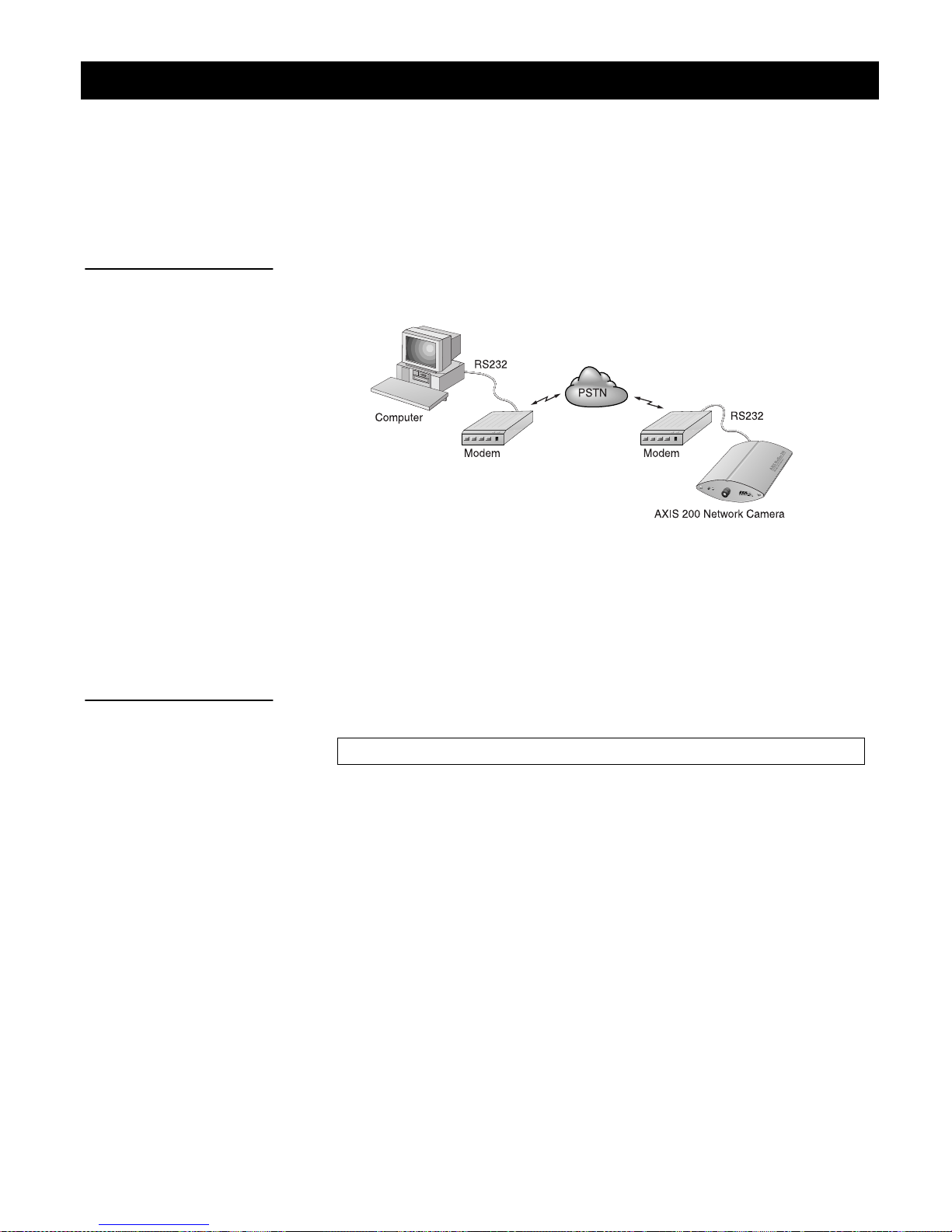
Modem Connection
File Transfer
By connecting the AXIS 200 to a modem as detailed below, it is
possible to download snapshot images to remote computers using
standard modem equipment.
Configuration of the serial port for modem connection
Snapshot data and configuration data may be transferred over the
serial link using the zmodem protocol. This protocol is supported by
most UNIX and PC/Mac communications packages.
To initiate a file transfer, simply type the
command followed by the
sz
filename of file you wish to transfer, as follows:
sz fullsize.jpg
Many communication packages allow automatic download of
snapshot files, i.e. the program will detect the file transfer starting, and
then proceed to take care of it. However, should your
communications package not support this, you will need to manually
select 'receive zmodem' (or similar) from with the program.
A successfully transferred snapshot file is in JPEG compressed image
format, which is precisely the same as if the picture were saved from
within a browser. Consequently, the downloaded file is an identical
copy of a snapshot representation held within your AXIS 200 file
system.
Page 55

AXIS 200 User’s Manual Section 5: Using the AXIS 200
53
Notes:
❏ Before files can be transferred from your AXIS 200, the host and
remote modems must be configured correctly. Refer to Appendix
E - The Auxiliary IO Port for further details.
❏ A typical zmodem session is displayed on page 85.
Page 56

54
Section 5: Using the AXIS 200
AXIS 200 User’s Manual
Page 57

AXIS 200 User’s Manual Appendix A: Troubleshooting
Appendix A Troubleshooting
This appendix describes some of the common problems that AXIS
200 users have experienced previously and aims to provide useful
information that will help you resolve any difficulty you may have, as
expediently as possible.
Symptoms, possible causes and remedial actions are listed within a
reference table and references to other information sources are also
discussed.
The Log File
55
Obtaining the File
The AXIS 200 log file records all commands executed within the unit
and can prove a useful diagnostic tool when attempting to resolve any
problems that might occur.
If you cannot resolve your problem after referencing the information
contained in this appendix and on the AXIS 200 FAQ, we suggest that
you send the following to the AXIS support desk:
• A brief description of the problem
• The log file
• The config file
• If relevant, an example of a poor image
To obtain a copy of the log file, simply type the following command
into the URL of your Web browser:
http://<cameraname>/log/messages
Page 58

56
Appendix A: Troubleshooting
AXIS 200 User’s Manual
Examining the File
The file can be examined directly using any text editor and would
typically contain information as detailed below:
Wed Nov 5 15:12:18 Info: BOOT
Wed Nov 5 15:12:36 Warning: Modem failed to
acknowledge hangup.
Wed Nov 5 15:12:48 Warning: Modem not responding
at 9600 BPS.
Wed Nov 5 15:12:56 Warning: Modem failed to
acknowledge hangup.
Wed Nov 5 15:13:01 Info: Modem ready for incoming
calls.
Wed Nov 5 15:13:16 Info: SMTPC.exec, trying to
connect to (193.13.178.2)
Wed Nov 5 15:13:24 Info: SMTPC.exec, mail sent
Wed Nov 5 15:13:34 Error: FTPC.exec, failed to
put
"tmp/fullsize151320.jpg", (def)
Typical AXIS 200 Log File
Page 59

AXIS 200 User’s Manual Appendix A: Troubleshooting
Symptoms, Possible Causes and Remedial Actions
Symptoms Possible causes Remedial actions
The AXIS 200 cannot be
accessed from a Web
browser.
The Internet address is
already used.
To check that the Internet address for your AXIS 200 is
unique:
1. Start a DOS window.
57
The Internet address is
located within a different
subnet.
2. Type
The reply subsequently returned will provide some explanation as to the cause of the problem. The possible replies
can be interpreted as follows:
ping x.x.x.x
address of the AXIS 200.
, where x.x.x.x is the Internet
bytes = 32 time = 2 ms......
The Internet address is already used and cannot be used
again. Obtain a new Internet address.
destination host unreachable
The AXIS 200 is not within a reachable network node.
Obtain a new Internet address.
request timed out
This Internet address is not in use by anyone and is available for use with your AXIS 200.
In Windows 95 or Windows NT, check that the Internet
address for your AXIS 200 is within the same subnet as
your workstation by following these steps:
1. Click "Start", "Settings", "Control Panel" and "Network".
2. Specify the TCP/IP adapter and click on “Properties”. In
Properties, click "IP Address".
In Windows 95, the ARP
table was empty when
you tried to set the
Internet address.
Check that the first 3 numbers within the Internet address of
your AXIS 200 matches the first 3 of your workstation. If
not, your AXIS 200 is in a different subnet and the Internet
address cannot be set from this workstation. Obtain a new
Internet address.
In Windows 95, the ARP command cannot be used if you
have an empty ARP table.
arp -a
Type
ping an existing unit on your network before you can download the Internet address to the AXIS 200 using ARP.
to view the ARP table. If it is empty, you must
Page 60

58
Appendix A: Troubleshooting
Symptoms Possible causes Remedial actions
The Pow er indicator is not
constantly lit, or the Net
indicator is not flashing
randomly.
Faulty cabling. To verify that the cables work, ping the address of a known
existing unit on your network.
If the cabling is OK and your network is reachable, you
should receive the following reply:
...bytes = 32 time = 2 ms,
or something similar.
The Snapshot and Net
indicators are flashing
every 0.5 seconds
Your AXIS 200 works
locally, but not externally.
No image using Refresh
and/or
Slow updating of
snapshots using
Server Push
Triggering Difficulties with
CRON scripts
Hardware failure. Contact your Axis dealer.
Firewall protection Check the Internet firewall with your system manager.
Default routers required Check whether you need to configure the default routers
settings.
The Internet site is too
heavily loaded.
Complex images, i.e.
those containing great
picture contrasts, have
greater filesize and thus
place greater demand on
the available file space
within the AXIS 200.
Unable to triggering on
both positive and negative transitions of the Control Button and/or IO
(double-edged triggering).
Use a script running on your web server to relay images
from the AXIS 200 to the Internet. This is particularly important when generating zoom and hugesize images.
The memory constraints become significantly more acute if
the same snapshot is accessed by multiple clients.
Try limiting the number of clients.
Repetitive trigger conditions occurring in quick succession
of one another, maybe missed. This is because the command initiated by the first trigger event may not have been
fully executed prior to the second event occurring. This scenario is demonstrated in the illustration below:
Command
AXIS 200 User’s Manual
Command
?
Command
T1
Tr igger
This feature has particular significance when using commands that take a relatively long time to process, e.g. email,
ftp, especially if they are conjugated with a loop statement.
See also page 92.
T2 T3
Time
Page 61

AXIS 200 User’s Manual Appendix A: Troubleshooting
Symptoms Possible causes Remedial actions
Cannot access the
modem connected to the
serial port of the AXIS
200.
A series broad vertical
white lines appear across
the image.Gray image in
bright day light conditions.
Inferior picture definition
in strong sunlight.
Noisy snapshots. If you use the AXIS 200 in
Bad focus. Focus is not adjusted cor-
Bad snapshot images. White balance set incor-
Modem not set for
XON/XOFF
Local echo not disabled
The CCD sensor
becomes overloaded
when the light is too
bright.
When focusing the camera on panoramic views,
particular care should be
taken with both the White
Balance setting and the
physical location of the
camera. This is because
the AXIS 200 functions
much the same as an
ordinary camera in these
circumstances, where too
much light entering the
camera produces an
over-exposed image.
a low light environment
the image might be noisy.
rectly
rectly.
Display configured incor-
rectly.
Ensure that the modem is set for XON/XOFF serial communication (note that CTS/RTS handshaking is not supported)
For US Robotics modems this is done using the command
AT&I1.
Disable Local echo mode using the command is ATE0.
Save the changes in the NVRAM of the modem using the
command AT&W.
Turn the AXIS 200 in a direction to avoid sun light reflexes.
Try adjusting the Brightness parameter. If this does not
help, you need an optical gray filter which reduces the light
by e.g. 10 %.
Av oid pointing the camera directly into the sunlight. In sensitive locations it may be worthwhile installing a sun filter or
shield for your camera. Attention to the White Balance setting is also highly recommended.
The AXIS 200 produces good definition of images in twilight
darkness. By using the camera in automatic mode a good
quality picture is achievable even in relative darkness.
Caution !
The CCD (charged coupled device) within the AXIS 200
may become damaged permanently if the camera lens is
exposed to too much direct sunlight.
To resolve this problem, you effectively need to get some
more light into the camera. The performance of the AXIS
200 is best in 100-1.000 lux.
Adjust the focus of the camera by turning the lens carefully
until you get a sharp image. Normally, the white dot on the
lens should be at the 12 o’clock position. If this does not
help, rotate the lens a full turn, and check again.
Refer to page 30 for information on how to set the White
balance.
Within Display Properties, configure your display to show at
least 65'000 colors, i.e. at least 16-bit.
Using only 16 or 256 colors on your computer will produce
dithering artifacts in the image.
59
Page 62

60
Appendix A: Troubleshooting
Symptoms Possible causes Remedial actions
Reduced image quality
for distant objects.
Gray image The CCD sensor gets
Wrong colors The camera adjusts its
Generally, objects at
close-to-medium proximity of the AXIS 200 will
appear with a high image
quality. More far-distanced objects are however displayed with less
detail when taking a panoramic view of surrounding landscapes.
overloaded if the light is
too bright. This can happen e.g. in bright day light
conditions.
brightness and its colors
automatically and can
take up to sev eral minutes
for the camera to adjust.
Brightness parameter Modify the Brightness parameter. Ref er to
White Balance parameter Try changing the White Balance parameter. Refer to
This is a optical phenomenon that is common in all cameras. However, further attention to the White Balance setting may pay dividends in improving the quality of long
range views generally.
Refer to page 30 for information on how to set the White
Balance.
Adjust the Brightness parameter. If this does improve the
image you may need use an optical gray filter which
reduces the light to e.g. 10%.
Wait a couple of minutes and check the image again.
page 25 and try using the default value.
Balance”
on page 30.
AXIS 200 User’s Manual
“Image Page”
on
“White
Page 63

AXIS 200 User’s Manual Appendix B: The Parameter List
Appendix B The Parameter List
This appendix contains a listing of the AXIS 200 configuration
parameters and also describes how to restore the factory default
settings for the unit.
The Config File
This table shows the AXIS 200 parameter list. The left and middle
columns show the parameter names and their default values as they
appear in the config file. The right column contains brief descriptions
of the parameters.
61
Parameter name Value Description
CONFIG MENU
NODE_ADDR. = 00 40 8c 18 00 86 Node address. Use when the unit is configured. Cannot be
changed.
ROOT_PWD. = PASS Root password. Always change the default password.
USERS. = User names and passwords of users that are authorized to
access the pictures taken by the AXIS 200. If empty, all users
have full access.
TCPIP MENU
TCP_ENB. = YES Enables the TCP protocol.
INT_ADDR. = 0.0.0.0 The AXIS 200 Internet address.
DEF_ROUT. = 0.0.0.0 All traffic directed outside the local network (according to the
NetMask) is sent to the default router. Any re-routing via other
routers is done automatically. The default 0.0.0.0 indicates that
no default router is set.
DNS_ADDR. = 0.0.0.0 The Internet address of the DNS server.identifying computers
with names instead of IP addresses.
MAIL_SERVER_ADDR. = 0.0.0.0 Name of the server that provides e-mail facilities.
RETURN_PATH. = The reply address for e-mails sent by the AXIS 200.
NET_MASK. = 0.0.0.0 Used to determine when the traffic should be sent via a router.
For example the normal class C mask is 255.255.255.0. The
default 0.0.0.0 indicates that automatic router sensing is used.
BOOTP_ENB. = yes Enables BOOTP Internet address setup.
RARP_ENB. = yes Enables RARP Internet address setup.
Page 64

62
Appendix B: The Parameter List
Parameter name Value Description
Camera specific
parameters
LOGO_X. = 10 Axis logo position in pixels, the horizontal coordinate.
LOGO_Y. = 10 Axis logo position in pixels, the vertical coordinate.
LOGO_SHOWN. = NO Enables Axis logo display.
CLOCK_X. = 1 Clock position in pixels, the horizontal coordinate.
CLOCK_Y. = 1 Clock position in pixels, the vertical coordinate.
CLOCK_SHOWN. = NO Enables clock display.
CLOCK_MODE. = AM/PM AM/PM or 24 hours time format.
Image appearance
parameters
COMPRESSION. = MEDIUM Determines snapshot compression and consequently file size.
BRIGHTNESS. = 5 Brightness control.
COLOR. = NORMAL Color control.
WHITE_BALANCE. = AUTOMATIC Control the white balance settings.
CONTRAST. = 5 Contrast control.
LIGHT_FRONT_LED. = YES Enables Snapshot indicator.
ROTATION. = NORMAL Snapshots can have varied orientation.
MIRROR. = NO Enables mirroring of image from right to left.
CACHE_TIME. = 0 Determines maximum cache period for snapshots,
DARKDETECT. = NO Enables black and white image generation for improved clarity
e.g the same snapshot will displayed for all requests within a 3
seconds period.
during low light conditions.
AXIS 200 User’s Manual
System Parameters
MODEM_TYPE. = Autodetect Modem or Null Modem.
SERIAL_MODE. = DISABLED Enables serial mode for ppp or zmodem access when set to
Full_Support, Inbound Only or Outbound Only.
SERIAL_BAUD. = 9600 Baud rate.
SERIAL_FLOW. = XON/XOFF Modem ser ver operation mode.
MODEM_INIT. = String of commands to be sent to the modem for setup. Used for
non-US Robotics modems.
BUSY_REDIAL. = 0 Specifies how many additional attempts the AXIS 200 will make
to establish a connection in case the line is busy.
TIME. = The current time.
DATE_SERVER. = 0.0.0.0 Internet address of the server that provides the actual time and
date.
DATESYNC_PERIOD. = 0 The date and time will be automatically updated according to the
specified intervals.
DATESYNC_PROTOCOL. = TIME The synchronization protocol used. Time (serial port 37), Day-
time (serial port 13) or NTP (UDP port 123).
DATESYNC_TIME_ZONE. = 0 The time zone adjustment as number of hours +/- UTC.
Page 65

AXIS 200 User’s Manual Appendix B: The Parameter List
Parameter name Value Description
TIMEADJ_WEEK. = 0 The time adjustment per week. Valid range is 0 to (-)32000 sec-
onds.
WATCHDOGTIME. = 12000 Do not change. Performs a hard reset if the server has reached a
deadlock.
INDEX_FILE. = INDEX
63
Page 66

64
Appendix B: The Parameter List
Factory Default Settings
If you should need to reset the AXIS 200 to its factory default settings,
you can use the Control button. Follow these steps:
1. Switch off the AXIS 200 by unplugging the power cord.
2. Press and hold the Control button while you switch on the AXIS
200. Keep the Control button pressed until the Snapshot
indicator flashes at regular two second intervals.
3. Release the Control button and wait at least two seconds (one
flash of the Snapshot indicator).
4. Press and hold the Control button for at least five seconds until
the Snapshot indicator remains constantly lit.
AXIS 200 User’s Manual
Note:
5. If you need to restore the default Internet address, press and hold
the Control button once again until the Snapshot indicator starts
flashing. Otherwise, the Internet address setting remains
unchanged.
6. The AXIS 200 is now reset to factory default settings. Restart the
AXIS 200 by switching it off and on.
❏ The node address (NODE_ADDR parameter) remains
unchanged, but all other parameters are reset.
Page 67

AXIS 200 User’s Manual Appendix C: Updating the Software
Appendix C Updating the Software
The AXIS 200 is equipped with Flash Memory which means that its
server software can be updated using FTP. This appendix describes
how this operation can be performed.
Obtaining Updated Software
The latest version of the AXIS 200 server software is available free of
charge from Axis or your local distributor. You may obtain this
software over the Internet or via anonymous FTP.
65
Over the Internet
The npsload program used for downloading the AXIS 200 software via
the parallel port, is also available free of charge at
ftp://ftp.axis.com/pub/axis/software/prt_srv/utility/flash/.
Simply follow the appropriate hyperlinks, starting with “Software
Updates” from within the Home Page of the AXIS 200, or enter
http://www.axis.com/techsup/cam_servers/cam_200/ within the
URL of your Web browser.
Typically, the software update file is called
where
x_xx
indicates the software version. This self extracting archive
200_x_xx.exe
,
file unpacks the associated data and text files upon execution. It is
recommended that you save this file in your root directory.
Flash Memory The
AXIS 200 server software is stored in Flash memory.
This memory is provided by a silicon chip that just like
any other ROM device, retains data content even after
power is removed. However, Flash memory is unique
because it allows its data to be erased and re-written.
This means that you can install software updates for
AXIS 200 as soon as they become available, without
your
having to replace any parts. The new software can be
simply loaded into the AXIS 200 over the network.
Page 68

66
Appendix C: Updating the Software
AXIS 200 User’s Manual
Anonymous FTP
Log in to ftp.axis.com and go to the /pub/axis directory. Download
the software update file
software revision. It is recommend that you save this file in your root
directory. Proceed then by unpacking the .exe file to create the
associated binary and text files.
Upgrading the Software
Theoretically, there are two methods with which to update to the
AXIS 200 Flash memory:
• over the network using FTP or
• through the parallel port LPT1.
Normally, AXIS 200 should upgraded the over the network using
FTP. However, if for some reason the AXIS 200 becomes unavailable
over the network, it may be necessary to reload the software through
the parallel port.
200_x_xx.exe
,
where
x_xx
indicates the
Note:
Upgrading using FTP
Note:
❏ Updating instructions are also supplied with the software update.
Having obtained the upgrade software, install it into the AXIS 200 by
following the instructions below:
1. Reset the AXIS 200 by powering it off and then on again.
2. Start an FTP session and log in to the AXIS 200 as
the root password. By default this is set to
pass
3. Set FTP to binary mode using the command
.
bin
root
.
, using
4. Download the new camera server software to you AXIS 200 by
using the command
put c:\200_1_31.bin flash
.
This process takes 30 - 60 seconds. The LEDs will flash slowly
during programming.
❏ If you need to force a download, e.g. when degrading to an older
software, use the syntax
put c:\200_1_31.bin FLASH
Page 69

AXIS 200 User’s Manual Appendix C: Updating the Software
67
Note:
Upgrading via the
Parallel Port
5. The AXIS 200 will report
programming finished OK.
Transfer complete, flash
, once the programming is
complete.
❏ In controlled environments, Flash memory upgrades provide a
very safe method for updating software. However, Flash products
may easily become damaged if this operation is left to
inexperienced persons. Units that become damaged due to misuse
will need to be sent back to your dealer who in such
circumstances, may charge for any necessary repairs. Therefore, it
is highly recommended that Flash memory upgrades are
performed by persons knowledgeable in this area.
You should only need to upgrade the AXIS 200 via the parallel port if
it is impossible to download the software using FTP. Therefore, you
are strongly advised to talk with your local distributor prior to
commencing with the procedures defined below:
1. Disconnect the power supply and the other external connectors.
2. Remove the two screws securing the back plate of the enclosure.
3. Carefully remove the PCB assembly from the enclosure paying
particular attention to how the earthing clips are secured on either
side of the circuit board. It is essential that these clips are replaced
properly when re-assembling the AXIS 200.
4. Connect the parallel cable between the PC LPT1 port of your
workstation and the 26-pin array of the AXIS 200 circuit board.
Make sure the parallel cable connector is mounted with the arrow
close to pin 1, facing the ETRAX chip located in the middle of
the pcb.
5. Reconnect the power lead to the AXIS 200.
6. Issue the following command from the DOS prompt to
commence the loading sequence:
npsload -1 -n 200_1_31.bin
Page 70

68
Appendix C: Updating the Software
AXIS 200 User’s Manual
Notes:
❏ Do not forget to use the
switch that indicates that the firmware
-n
file has a built-in loader.
❏ The network LED will flash during the loading sequence. This
normally takes between 30 secs and 4 minutes to complete.
Page 71

AXIS 200 User’s Manual Appendix D: Technical Specifications
Appendix D Technical Specifications
69
Network Systems
Web Browsers
Protocols
Network
Management
Software Updates
All systems running TCP/IP using a HTTP browser and supporting
JPEG files, HTML version 0.9 or higher, e.g. Netscape Navigator
1.22 or higher, and Microsoft Internet Explorer 1.0 or higher.
Netscape Navigator
Microsoft Internet Explorer and Web TV
Oracle Power Browser
NCSA Mosaic
Chimera
HTTP, FTP, TCP, IP, ARP, RARP, BOOTP, SMTP, PPP and
ICMP.
Configuration and status via standard HTTP or FTP browser.
Flash memory allows central and remote software updates over the
network using FTP over TCP/IP. All software upgrades are free of
charge and are available from the Axis WWW server.
Camera Resolution
The AXIS 200 supports the following resolutions:
Format Maximum
JPEG 704 * 576 approx. 90 kbytes approx. 60 kbytes approx. 30 kbytes
JPEG 352 * 288 approx. 60 kbytes approx. 30 kbytes approx. 15 kbytes
JPEG 176 * 144 approx. 30 kbytes approx. 15 kbytes appr ox. 8 kbytes
The resultant file size will is dependent upon the camera settings,
lighting conditions and the snapshot object. However, image objects
of a uniform shape generally require less detail and consequently
generate smaller snapshot files.
Resolution
Picture Quality
High
Picture Quality
Medium
Picture Quality
Low
Page 72

70
Appendix D: Technical Specifications
AXIS 200 User’s Manual
Performance
Network Attachment
Hardware
Optical Unit
The AXIS 200 uses a RISC CPU and hardware compression chips for
the JPEG transformation. A full size, full color JPEG file is created in
less than a second. However, inherent delays created by your network
and/or the Internet will also need to be added when considering the
overall time required to generate a picture.
10baseT (RJ-45) twisted pair Ethernet.
CPU: 32-bit RISC processor (ETRAX).
Flash PROM: 1 Mbyte
RAM: 1792 kbytes.
• Manual focus: digital, 16 million colors, 24 bits, 0.2 in (0.5 cm)
to infinity
• Picture angle: 51 deg horizontal, 39 deg vertical
• Illumination range: 10 - 5 000 lux
Auxiliary
Input/Output
Serial Connector
Accessories
• CCD: 1/4 in, 768 * 582 pixels
• Shutter speed: 1/50 - 1/10000 seconds
• Optical Focus: 4 mm focal length
(comparable to 35 mm on a regular camera)
A Mini-DIN 8-pole external connector is provided for auxiliary
connections to the AXIS 200. The functionality of this connector is
fully discussed in “Appendix E - The Auxiliary IO Port” .
A 9 pin D-sub connector provides the physical RS232 serial interface
to a modem server within the AXIS 200. The functionality of this
connector is fully discussed in “Appendix F - The RS232 Serial Port” .
A camera mini-tripod that can be used standalone or mounted on a
wall. This is supplied with each unit and uses a standard camera
1/4 inch nut.
Page 73

AXIS 200 User’s Manual Appendix D: Technical Specifications
71
Operating
Te m p e r a t u r e
Humidity
Approvals
Size
Wei gh t
Power Supply
40-105°F (5-40°C).
20-80% RHG, non-condensing.
EMC: FCC Class A, CE:EN 55022/1987,EN50082- 1/1992
Safety: EN 60950, UL, CSA.
Height 1.9 in (4.8 cm). Width 4.9 in (12.5 cm).
Length 6.1 in (15.5 cm).
1.0 lb. (0.5 kg), excluding power supply.
12V AC, 9.6 VA, via external power supply (PS-D).
All specifications are subject to change without prior notice.
Page 74

72
Appendix D: Technical Specifications
AXIS 200 User’s Manual
Page 75
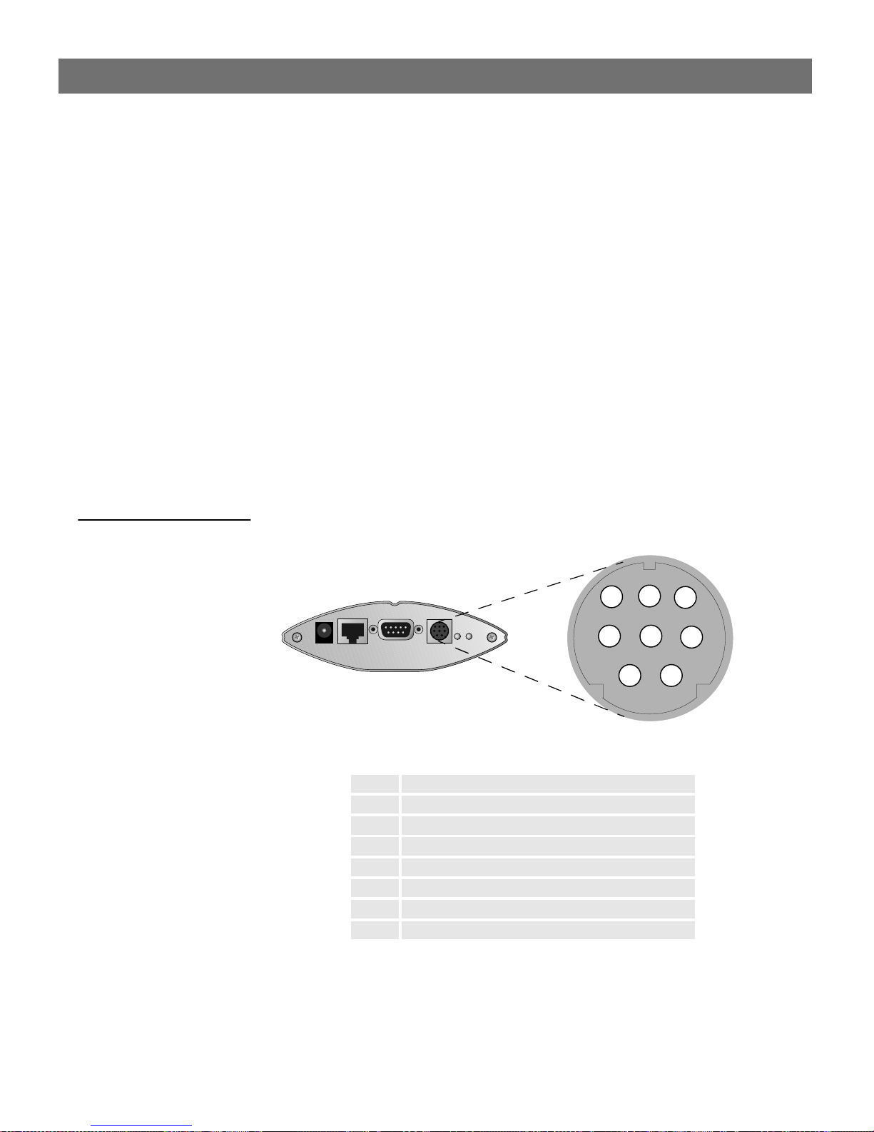
AXIS 200 User’s Manual Appendix E: The Auxiliary IO Port
Appendix E The Auxiliary IO Port
A Mini-DIN 8-pole external connector is provided for auxiliary IO
connections to the AXIS 200. This appendix discusses the additional
functionality that this connector provides.
Physical connection
The auxiliary IO connector provides the interface to one relay switch
output and two digital inputs.
73
Pinout
A diagram for the auxiliary IO connector and a pinout table are
detailed below:
7
8
5
2
Rear view of the AXIS 200
Pin Function
1 Relay switch (Max 24V AC/DC, 100mA)
2 Relay switch (Max 24V AC/DC, 100mA)
3 PAL video output upside down (1 Vpp /75 ohm)
4 NC
5 NC
6 Input 1
7 Input 2
8 GND
6
4
3
1
Page 76

74
Appendix E: The Auxiliary IO Port
AXIS 200 User’s Manual
Caution!
GND on the IO connector is not connected directly to the power
connector. Always use two independent power sources! Connecting
GND to the power connector will permanently damage your AXIS
200.
Controlling and Monitoring
IO Files
The status of the input/output interface can be monitored and
controlled by the IO software within your AXIS 200. From your Web
browser, you can access the IO control file in order to either drive the
relay output or monitor the status of the digital inputs.
To access the IO file, enter the following URL:
http://cameraname/io/
You will require
to supply a user name and password. Login as
root password (default =
access to reach these files and will now be asked
root
and supply the
pass
root
).
Relay Output
Once access is granted, the following files are displayed:
relayon.txt
relayoff.txt
input.txt
You can use the relay output to drive directly a maximum load of 24V
AC/DC at 100mA. By connecting additional relay circuitry, you can
also use this output to drive heavier loads.
You can drive the relay off and on simply by clicking
or
relayon.txt
in the above URL. Clicking on either of these will
relayoff.txt
return either of the following messages, respectively:
Relay is Off
Relay is On
Page 77

AXIS 200 User’s Manual Appendix E: The Auxiliary IO Port
75
Note:
Digital Inputs
❏ You can also control the relay switch via a CRON script using the
snapshot command.
The two digital inputs on pins 6 and 7 of the connector make it
possible to trigger your snapshots on chosen events. However, you
must use a CRON script to implement this functionality. See “CRON
Script” on page 39.
By connecting a digital microcircuit to a particular door for example,
it is possible to take a snapshot on each occasion that it opens or
closes.
AXIS 200
Aux.
Con.
6
o
7
o
.
Micro-switched door
Infra-red switch
o
o
CPU
Digital input 1
Digital input 2
5V
.
.
GND
Relay +
Relay -
Relay
Switch
8
.
o
1
o
o
o
2
o
Optional
Switch
o o
24V DC
Relay
o
o
Mains Power
Appliance
o o
x
o
Schematic diagram of the AXIS 200 Auxiliary Connector
- displaying a possible application
Status information for each of the two digital inputs is presented
within a text string. The status of the inputs can be ‘read’ by clicking
on the
input.txt
parameter in the above URL. The string will
amongst other things define the time and duration of the last trigger
event for the each input:
input:1 current:0 last:1 time:12.22 pulse:2
input:2 current:1 last:0 time:14.46 pulse:6
Page 78

76
Appendix E: The Auxiliary IO Port
This table describes each digital input text string:
String Description
input: Input reference
(Input 1= pin 6, Input 2 = pin 7)
current Current port status
(Logical high = 1, Logical low = 0)
last Result of previous ‘read’ operation
time The time of the last change on the input pin.
pulse The number of logical one-to-zero transi-
tions on the I/O pin, since the last read.
AXIS 200 User’s Manual
Note:
❏ The way in which you use the auxiliary connector is of course, for
you to decide. Axis does not provide any application software, but
instead allows you to determine how this connector is best
utilized. Naturally, we would be more than pleased to learn of any
interesting applications that you might develop!
Page 79

AXIS 200 User’s Manual Appendix F: The RS232 Serial Port
Appendix F The RS232 Serial Port
A 9 pin D-sub connector provides the physical connection for the
RS232 serial interface of the AXIS 200. This connector is provided for
connecting accessory equipment to the camera.
This appendix discusses the functionality of the RS232 serial interface
and how to how to set up a modem connection for the AXIS 200.
Physical connector
77
Pin assignment
Caution!
A diagram of the connector and a pin assignment table for the AXIS
200 are detailed below.
Pin Function
2
1
6
Rear view of the AXIS 200
4
3
5
7
9
8
1 NC
2 - RXD
3 - TXD
4 RTS
5 GND
6 CTS
7 RTS
8 NC
9 NC
❏ GND on the serial port is not connected directly to the power
connector. Always use two independent power sources!
Connecting GND to the power connector will permanently
damage your AXIS 200.
Page 80

78
Appendix F: The RS232 Serial Port
Setting Up the AXIS 200 Modem Server
A modem server provided within your AXIS 200 makes it possible to
transmit snapshot images over the PSTN. By connecting the AXIS
200 to a modem, it is possible to download snapshot images to remote
computers using standard modem equipment.
AXIS 200 User’s Manual
XON/XOFF
Note:
Configuration of the serial port for modem connection
The AXIS 200 modem server utilizes XON/XOFF handshaking. In
this mode of operation, a straight-through RS232 cable is all that is
required for connecting the modems to both the computer and the
AXIS 200. That is, the transmit and receive signals on pins 2 and 3 of
the cable do not need to be reversed.
❏ This is the common wiring schedule for RS232 cables supplied
with most of today’s popular modems.
Page 81

AXIS 200 User’s Manual Appendix F: The RS232 Serial Port
79
CTS/RTS
Note:
In future releases of the software, the CTS/RTS handshaking will be
supported. However, to enable this mode of transmission in current
versions of the AXIS 200, the wiring schedule for the connecting
RS232 cables must look like this:
AXIS 200
AXIS 200 signal
name
NC 1 8
-RXD 2 3
-TXD 3 2
RTS 4 20
GND 5 7
CTS 6 6
RTS 7 4
NC 8 5
NC 9 22
(9 pin
DSUB Female
connector)
Modem
(25 pin
DSUB Male
connector)
❏ Some modems are supplied with a cables terminated by 25 pin
DSUB connectors at both ends. Should you have a cable similar
to this, you will need to use a 25 pin Male - 9 pin Female 'genderbender' with the pin assignment detailed above. Null modem
cables will not work!
Page 82

80
Appendix F: The RS232 Serial Port
AXIS 200 User’s Manual
Configuring your
modems
Before files can be transferred from your AXIS 200, the host and
remote modems must be configured correctly.
Follow these instructions to configure a US Robotics 28k8+ modem:
1. Connect the modem to your terminal.
2. Check that the modem is responding by issuing the
command.
at
3. Continue your configuration in accordance with the session
detailed below (user commands are written in
at
OK
at&f
;load factory default settings
OK
at&b1
OK
at&h2
OK
atm0
OK
ate0
OK
at&w
OK
---------ready ----
;lock DTE-DCE baud rate
;xon/xoff handshaking on
;turn speaker off
;command echo off
Note: this inhibits the display
of entered commands.
;save settings to modem
bold
text):
4. To make sure that your modem reloads the established settings on
5. To check that the settings have been saved, turn the modem off
6. Type
The new settings dump that is displayed should be identical to those
previously saved. If it is, your modem is now ready to be connected to
the AXIS 200!
ati4
each occasion it powers up, issue the
command once the
configuration is complete.
and power it on again.
ati4
You should not see your own typing at this point,
.
but if you do, check your modem DIP switches and make sure
ate0
that the
command was issued successfully.
Page 83

AXIS 200 User’s Manual Appendix F: The RS232 Serial Port
81
Notes:
Ty pi c al m od e m
settings
❏ The above session was performed on a US Robotics modem.
Please be aware that the required settings for other types of
modems may differ from those defined above. Axis are currently
checking the compatibility of the AXIS 200 with other popular
modem types and will release configuration details for these
shortly.
❏ Some modem manufacturers require you to set a DIP switch to
disable command echoing. e.g. USR Sportster 28k8 modems
require DIP switch 4 to be set to the DOWN position.
Typical US Robotics Sportster Vi 33600 Faxmodem settings are
defined below:
B0 E0 F1 M0 Q0 V1 X1 Y0
BAUD=115200 PARITY=N WORDLEN=8
DIAL=PULSE ON HOOK
&A1 &B1 &C1 &D2 &H2 &I0 &K1 &M4 &N0 &R1
&S0 &T5 &U0 &Y1
S00=000 S01=000 S02=043 S03=013 S04=010
S05=008 S06=002 S07=059 S08=002 S09=006
S10=007 S11=070 S12=050 S13=000 S14=000
S15=000 S16=000 S17=000 S18=000 S19=000
S20=000 S21=010 S22=017 S23=019 S24=000
S25=005 S26=000 S27=001 S28=008 S29=020
S30=000 S31=000 S32=000 S33=000 S34=000
S35=000 S36=000 S37=000 S38=000 S39=000
S40=000 S41=000 S42=000 S43=200 S44=015
S45=000 S46=050 S47=000 S48=084 S49=000
S50=000 S51=000 S52=000 S53=000 S54=064
S55=000 S56=000 S57=000
Note:
❏ The screen dump for your modem might differ from the above, as
LAST DIALED #:
OK
the settings can vary between modem types.
Page 84

82
Appendix F: The RS232 Serial Port
AXIS 200 User’s Manual
Configuring
the AXIS 200
Using the
Web browser
Using the
Control button
Once you have set up your modems, you need to configure your AXIS
200 for modem control. You can use any of these methods:
• Web browser
•FTP
• The Control button
1. On the Configuration - Modem page, enable serial mode by
setting the Serial mode parameter to Full Support.
2. Connect the modem to the AXIS 200.
3. Turn the modem on.
4. Wait a few seconds and then power up the AXIS 200.
The new settings will now take effect.
For remote installations that are not directly connected to a LAN, you
can alternatively configure the AXIS 200 for serial mode operation as
follows:
1. Restart the AXIS 200 by removing and then re-inserting the
power connector.
2. Wait 10 seconds.
3. Press the Control button and keep it pressed until the Snapshot
indicator flashes.
4. Release the Control button.
5. Double click the Control button while the Snapshot indicator
continues to flash.
6. Wait until the Snapshot indicator stops flashing.
7. Restart the AXIS 200 by removing and then re-inserting the
power connector.
Page 85

AXIS 200 User’s Manual Appendix F: The RS232 Serial Port
83
Using FTP
1. Log in to the AXIS 200 with the command
where
address
cameraname
.
is the AXIS 200 host name or Internet
ftp cameraname
2. You will be prompted for user name and password. Use the user
root,
id
3. Issue the command
to a directory on your workstation
which has the default password
get config
to copy the AXIS 200 config file
.
4. Log out using any of the commands
quit, bye
pass
.
or
exit
depending on your FTP version.
5. Edit the AXIS 200 config file by setting the SERIAL_MODE
parameter to FULL_SUPPORT.
6. Start a new FTP session.
7. When you are logged in, issue the command
put config
download the edited file to the AXIS 200.
8. Log out again.
Dialing the server
The Help menu
You will reach the AXIS 200 modem server by dialing
where
nnnnnn
is the modem phone number, e.g.
ATDTnnnnnn,
ATDT555-1212
. The
AXIS 200 will then answer the call, and establish the connection.
Once the connection has been established, the AXIS 200 welcome
banner is displayed:
Welcome!
You are connected to the host shell of your AXIS
Camera Server.
Try 'help' for a list of available commands, or
just ‘sz fullsize.jpg’ to download an image.
Type the following to view the help menu:
$ he
Page 86

84
Appendix F: The RS232 Serial Port
AXIS 200 User’s Manual
Note:
The help menu is displayed
Help Display help text
Date Get current date and time
SetDate Set current date and time
Version Print current software
Su Become super-user or a nother
SoftReset Protocol reinit of Axis 200
HardReset Complete reboot of Axis 200
Sz Send a file using zmodem
Exit Disconnect
Quit Disconnect
Goodbye Disconnect
:
version
user
protocol
❏ All commands are case insensitive.
Access rights
Abbreviations
Super-user
Zmodem
The commands available to each user from within the welcome menu
will depend upon their user privileges.
All non-destructive commands can be abbreviated to shortest
unambiguous form. However, because of their severity, the
HardReset
and
SoftReset
commands must be entered in their
entirety.
Su[username
The ‘
‘
Su root
’ will, if you supply the correct password when prompted for
it, give you root access and enable use of the
]’ command is used to become another user, e.g.
Reset
and
SetDate
commands.
Once connection to the AXIS 200 has been established, you can
initiate a file transfer. Simply type the ‘
’ command followed by the
sz
filename of file you wish to transfer, as follows:
sz fullsize.jpg
Page 87

AXIS 200 User’s Manual Appendix F: The RS232 Serial Port
A typical zmodem session is detailed below:
at
OK
atdt555-1212
Welcome!
You are connected to the host shell of your AXIS
Camera Server.
Try 'help' for a list of available commands, or
just 'sz fullsize.jpg' to download an image.
$ sz fullsize.jpg
**B00000000000000
>> Notice: Redirecting stdin/stdout.
>> Notice: Executing the command ``cd ~/dl/modem
; rz ; xv *& ; sleep 2;
rm *''.
rz waiting to receive.
Receiving: fullsize.jpg
Bytes received: 24188/ 24188: 3020 Bytes per
sec
Transfer complete.
Transfer complete.
$
85
Typical zmodem session
Page 88

86
Appendix F: The RS232 Serial Port
AXIS 200 User’s Manual
Page 89

AXIS 200 User’s Manual Appendix G: Camera Applications
Appendix G Camera Applications
With an estimated 60 million Web sites on the Internet today, it is
important that Internet advertisers create their Web pages in a way
that is interesting to visitors. Web designers can benefit from adding
attractive links to exciting ‘live’ pictures within their Web pages.
Live Internet and intranet picture publishing, visual surveillance and
process monitoring represent just a few of the many applications for
which you can use your AXIS 200.
87
Application Ideas
The only real limitation for the number of applications to which the
AXIS 200 may be suited is your fantasy. Some of the more obvious
applications ideas are:
• Adding ‘live’ pictures to your Web pages. Snapshot pictures may
be triggered and viewed from anywhere in the world.
• Monitoring and surveillance of industrial processes. Monitor the
production flow in any kind of industry. Let the AXIS 200 save
snapshots at specified times for quality control and generic surveillance purposes.
• Various kinds of security surveillance applications.
• Monitoring of conference rooms, e.g. how many and which people are present in a meeting.
• Creating a company photo catalog for use over the intranet.
• Integrating the AXIS 200 into your CGI scripts in order to create
your own applications.
• Fun applications. Who visits the coffee machine most in your
organization?
Page 90

88
Appendix G: Camera Applications
AXIS 200 User’s Manual
Application Examples
The list below contains links to a number of Web sites, and illustrates
the wide range of applications suitable for the AXIS 200:
• Surveillance of the company entrance door:
http://www.axis.com/neteye/rm_demo/front_doors.html
• Child monitoring system for daycare centers and preschools:
http://www.kindercam.com/
• Construction pictures from the Riverview Wastewater treatment
plant project:
http://www.pirnie.com/pws/riverview.cfm
• Elephant bath at the National Zoo, Washington D.C.:
http://www.si.edu/organiza/museums/zoo/zooview/exhibits/elehouse/elephant/bath.htm
• Underwater pictures at Hawaii’s Waikiki Aquarium:
http://waquarium.mic.hawaii.edu/coralcam/
• View of the prayers, celebrations and special ceremonies at the
Jewish Kotel (the Western) Wall:
http://www.virtual.co.il/city_services/kotel/kam/index.htm
Note:
• Traffic monitoring in New York City:
http://www.mte.com/webcam/
Axis is not responsible for maintaining the web sites listed above.
However, you will find links to a number of applications and demos at
the AXIS 200 web site at http://www.axis.com/products/cam_200/
Page 91

AXIS 200 User’s Manual Appendix H: CRON Script Command Reference
Appendix H CRON Script Command
Reference
This appendix details the syntax of the CRON script commands.
For information on how to use the CRON scripts with your AXIS
200, refer to “CRON Script”, on page 39.
Script Format
A CRON script for the AXIS 200 can include one or several entries.
The CRON script entries use this format:
89
# <comments>
<triggering condition> :
<commands>;
%
where
and
<triggering condition>
<minute> <hour> <day> <month> <weekday> <input and
boot event (optional)>
<commands>
includes one or several CRON script commands.
includes the following fields:
Page 92

90
Appendix H: CRON Script Command Reference
Commands
AXIS 200 User’s Manual
alert
Syntax
Options
The alert command sends messages to a remote host.
alert [-host HOST] [-port PORTNUMBER]
[-message STRING];
-host
-port
-message
Specifies the host name or Internet address of the remote host.
Specifies the TCP port number in the range [0..65534].
Specifies the message that will be sent to the remote host. The
message must be surrounded by quotation marks. Hexadecimal
coded messages must be preceded by
\0x
, e.g.
"\0x04"
for the
non-printed character EOT. To include a quotation mark, it
.
must be preceded by a backslash, e.g.
\"
Example
# This command will send the message "Alarm
# "0013" from AXIS 200" to the remote
# input port 1 goes high.
* * * * * /I1:
alert -host 172.16.253.80 -port 2703 -message "Alarm
\"0013\" from AXIS 200";
%
host when
ftp
The ftp command uses the standard File Transfer Protocol (FTP) for
transferring an image from your AXIS 200 to a remote host.
Note:
❏ The ftp command keeps the connection open during each file
transfer.
Page 93

AXIS 200 User’s Manual Appendix H: CRON Script Command Reference
91
Syntax
Options
ftp [-host HOST] [-user USERNAME] [-pass PASSWORD]
[-src SOURCEFILE] [-dest DESTINATIONFILE]
[-temp TEMPORARY_DESTINATIONFILE] [-loop LOOPTIME]
[-time TOTALTIME];
-host
Specifies the host name or the Internet address of the remote
host. If specifying the host name, performance is slightly
decreased due to the DNS lookup. If no host is specified, the
compiler will complain.
-user
The username used when logging on to the remote host. If no
username is specified, the compiler will complain.
-pass
-src
The password used when logging on to the remote host.
Specifies the source filename. If this parameter is omitted, the
fullsize.jpg
file will be sent. If an erroneous file name has
been specified, no action will be taken during execution.
-dest
Specifies the name and whole path of the destination file. If
this parameter is omitted, the destination file name will be the
same as the source filename. The maximum length of a
destination filename is 255 characters. You can add as many
destination files as required, separated by a space.
Note:
You can add time stamps, such as time, date and file indexes, to
the destination filename. This is useful for example when you
are transferring a series of files.
substitution can be used with the first destination file
❏ The
rS-E
only. To make sure all the files in a series are captured, you must
specify a sufficiently long execution time in the time attribute.
Page 94

92
Appendix H: CRON Script Command Reference
The following table lists the available time stamp variables.
Every substitution must be proceeded by a dollar sign ‘
The current second in the range 00-59.
$s
The current minute in the range 00-59.
$m
AXIS 200 User’s Manual
’.
$
-temp
-loop
$h
$d
$n
$y
$Y
$rS-E
The current hour in the range 00-23.
The current day of the month in the range 01-31.
The current month in the range 01-12.
The current year without the century in the range 00-99.
The current year including the century.
Inserts an index number starting from number
S
through all the numbers including the number E. If you
, it will be interpreted as a very large
leave out number
E
number.
Specifies a temporary name for the file destination. This is to
prevent someone else from accidentally reading the file during
the download.
Specifies the time interval within which the command
should be repeated. Format:
h<hours>m<minutes>s<seconds>
.
-time
Specifies the total time the command should execute. Used
together with the loop attribute. Format:
h<hours>m<minutes>s<seconds>
.
Page 95

AXIS 200 User’s Manual Appendix H: CRON Script Command Reference
93
Additional Options
In addition to the options described above, the following optional
settings are also available:
-ctrlport
Specifies the TCP port number in the range [0..65534] to be
used as the control port for the FTP server.
-dataport
Specifies the TCP port number in the range [0..65534] to be
used as data port for the FTP server.
-to
Specifies the timeout, i.e. the FTP session will terminate when
the specified time limit has expired. Format:
h<hours>m<minutes>s<seconds>
.
However, these options can only be used via a text editor.
Page 96

94
Appendix H: CRON Script Command Reference
Example 1
# This command will log in as “elvis” with the
# password “presley” on the host with the Internet
# address 123.123.123.123, download a hugesize
# image with the name “king.jpg” and put
# it in the directory “/home/elvis” on the remote
# host. During the download, the file name
# “tmp.jpg” will be used.
* * * * * :
ftp -host 123.123.123.123 -user elvis -pass
presley -src hugesize.jpg -dest
/home/elvis/king.jpg -temp tmp.jpg;
%
AXIS 200 User’s Manual
Example 2
# This command will every hour, every 5
# seconds for 20 minutes, download a fullsize
# image and save the images with a time stamp in
# the filename.
0 * * * * :
ftp -src fullsize.jpg -host an.interesting.site
-dest tmp/full$h$m$s.jpg -user billy -pass
startrek -loop s5 -time m20;
%
Example 3
# This command will send 1001 consecutive fullsize
# images to “funny.host.name”. The first and last
# images will be named “fullsize1000.jpg” and
# “fullsize2000.jpg”, respectively. The command
# will run for 30 minutes.
* * * * * :
ftp -host funny.host.name -user cam -pass secret
-src fullsize.jpg -dest
/home/cam/tmp/fullsize$r1000-2000.jpg -time m30;
%
Page 97

AXIS 200 User’s Manual Appendix H: CRON Script Command Reference
95
mail
Note:
Syntax
Options
This command uses the Simple Mail Transfer Protocol (SMTP) for
sending images and files from your AXIS 200 to e-mail addresses.
❏ To use the mail command, you must specify the Internet address
of the mail server and a valid return address on the TCP/IP page.
mail [-s SUBJECT] [-a ATTACHMENTS] [-t RECIPIENTS];
A simple one-word subject does not require quotation marks. A
-s
subject with multiple words must be surrounded by quotation
marks.
Attachments such as images or files.
-a
The e-mail address of the recipient(s).
-t
Page 98

96
Appendix H: CRON Script Command Reference
Example 1
# This command will send an e-mail with the
# subject “Hello” and the attached file
# fullsize image to someone@company.com
* * * * * :
mail -s Hello -a fullsize.jpg -t
someone@company.com;
%
Example 2
# This command will send an e-mail with the
# subject “This “fullsize.jpg” was sent from my
# AXIS 200” to two recipients.
AXIS 200 User’s Manual
offline
* * * * * :
mail -s "This \"fullsize.jpg\" was sent from my
AXIS 200" -a fullsize.jpg -t someone@axis.com
anotherone@axis.com;
%
Example 3
# This command will send an e-mail with five
# attachments.
* * * * * :
mail -s "Some images from the summer house." -a
fullsize.jpg halfsize.jpg hugesize.ppm cronscript
config -t me@at.home;
%
This command terminates the current PPP connection. Used together
with the online command.
Syntax
offline;
Page 99

AXIS 200 User’s Manual Appendix H: CRON Script Command Reference
97
online
Syntax
Options
This command dials up a modem and establishes a PPP connection.
Used together with the offline command.
online [-dial NUMBER] [-user USERNAME -pass PASSWORD]
[-timeout TIME][-script “send expect send expect ...”];
-dial
-user
The phone number that will be sent to the modem as
ATDT<phone number>
. The number cannot include spaces.
Username used for authentication. Note that spaces are not
allowed in the username. Optional.
-pass
-timeout
Password. Required if a username is specified.
Terminates the online session after the specified time by
restarting the AXIS 200. Optional. Format:
h<hours>m<minutes>s<seconds>
-script
An optional script string of expect-send pairs to be sent over
the line. This must be the last option in the command.
If a send word is empty, i.e. if it contains single quotes (
‘’
),
nothing will be sent until the expect word is received.
If a word includes spaces, you must put it in single quotes.
For a login sequence, you can use the words
$(PASS)
in the
. They will be replaced by the arguments specified
-user
and
-pass
options, respectively.
$(USER)
and
If the string does not include an escape code, a carriage
return character will be appended automatically at the end
of the string. Valid escape codes are:
(tab).
(line feed) and
\t
(carriage return), \n
\r
At the end of the script, the AXIS 200 will enter the
negociation phase.
Page 100

98
Appendix H: CRON Script Command Reference
AXIS 200 User’s Manual
Example
Example
1
# This command will dial up a modem with number
# aNumber, and login with username aUser and
# password aPass. It will first wait for the
# string ‘ogin: ’ and send the username. It
# will then wait for the string ‘ass: ’ and send the
# password.
* * * * * /I1:
online -dial aNumber -user aUser -pass aPass
-script “‘’ ‘ogin: ’ $(USER) ‘ass: ’ $(PASS)”;
%
2
# This command will dial up a modem and wait for
# the prompt string ‘>’. It will then send the
# string ‘ppp defaults’. If the session has not
# terminated after 5 minutes and 30 seconds, the
# AXIS 200 will be restarted.
* * * * * /B:
reset
Syntax
Options
online -dial 5551234 -user bob -pass dylan
-timeout m5s30 -script “‘’ ‘>’ ‘ppp defaults’ ”;
%
This command resets the software or hardware of the AXIS 200.
reset [-soft] [-hard];
-soft
-hard
Reinitiates the AXIS 200 protocols.
Performs a complete reboot of the AXIS 200.
 Loading...