

Page 1

Azure 2000
Operator’s Manual
Page 2

AZUREM2.DOC 18.03.1999 12:40
Page 3

AZUREM2.DOC 18.03.1999 12:40
Useful Avolites phone numbers:Avolites England
Sales and service* (+44) (0) 181 965 8522
Service out of hours* (+44) (0) 831 17 8888
Fax (+44) (0) 181 965 0290
Email name@avolites.com
Website http://www.avolites.com
Distribution of Avolites products in USA:-
Avolites America
Sales and service* (+1) 423 938 2057
Fax (+1) 423 938 2059
*Before contacting Avolites for service enquiry please ensure that you have the
product serial number and the Software version. The serial number can be found
on the back of the desk and the software version is shown on the bottom line of
the VGA display.
The latest version of this manual (in Microsoft Word 97) and Azure
Software can be downloaded by modem from the Internet.
The small print :
No Liability for Consequential Damages
Avolites has a policy of continuous product and documentation improvement. As such the
detail within this manual may not match the operation of the Azure 2000.
In no event shall Avolites be liable for any direct, indirect, special, incidental, or
consequential damages or loss whatsoever (including, without limitation, damages for loss of
profits, business interruption, or other pecuniary loss) arising out of the use or inability to
use the Azure 2000 even if Avolites Ltd. has been advised of the possibility of such damages.
Because some jurisdictions do not allow the exclusion or limitation of liability for
consequential or incidental damages, the above limitation may not apply to you.
Reprint and revision history:
First produced December 1998
Issued with corrections Feb 99
A few minor amendments March 99
Page 4

AZUREM2.DOC 18.03.1999 12:40
This manual was written by Tim Mitchell, Sabre Technology Ltd Tel: 01482 831031
Page 5

AZUREM2.DOC 18.03.1999 12:40
TUTORIAL CONTENTS
1. WELCOME TO THE AZURE 2000 1
2. PATCHING 5
3. CONTROLLING DIMMERS AND FIXTURES 11
4. USING SHAPES 15
5. RECORDING AND PLAYING BACK MEMORIES 19
6. RECORDING AND PLAYING BACK CHASES 27
7. ENVIRONMENTS AND THE SCHEDULER 31
8. THE GRAPHICS TABLET 33
9. ADVANCED FEATURES 35
10. INTRODUCTION TO INTELLIGENT LIGHTING 37
REFERENCE MANUAL CONTENTS
1. SETTING UP THE CONSOLE 105
2. PATCHING 109
3. CONTROLLING DIMMERS AND FIXTURES 113
4. USING SHAPES 121
5. RECORDING AND PLAYING BACK MEMORIES 125
6. RECORDING AND PLAYING BACK CHASES 133
7. ENVIRONMENTS, THE SCHEDULER, SCRIPT FILES 139
8. USING THE GRAPHICS TABLET 145
9. ADVANCED FEATURES 149
10. THE PERSONALITY FILE SYSTEM 155
11. CONTACTS FOR FIXTURE MANUFACTURERS 166
12. GLOSSARY OF TERMS 168
13. BUTTON INDEX 174
14. INDEX 176
Pages in the Tutorial section have numbers below 100. Pages in the
Reference manual have numbers above 100.
Page 6

AZUREM2.DOC 18.03.1999 12:40
Page 7

Fehler! Formatvorlage nicht definiert.. Fehler! Formatvorlage nicht definiert. - Page 1
AZUREM2.DOC 18.03.1999 12:40
INTRODUCTION
1. Welcome to the Azure 2000
This manual is designed to help you get the most out of your Azure 2000
console. We have divided it into two sections.
?? This first section is a tutorial which gives you a step by step guide of
how to carry out the most common functions of the Azure 2000. This
section is printed on coloured paper.
?? The second section is a reference manual which tells you everything
there is to know about the Azure 2000.
To help you move between the two sections, we have made the chapter
numbering the same, so if you are using the tutorial and you want more
information, just look for the same chapter number in the reference
manual.
At the back of the reference manual there is a Glossary, explaining some
of the technical terms used in the manual, and an Index which can be
used to find what you need in either section of the manual. There’s also a
“button index” which you can use if you want to know what a particular
button does.
1.1 Setting up the Azure 2000
Before you can use the Azure, you need to make a few connections to it.
Ensure the power is off while making these connections.
Connect the mains inlet to an AC power supply. This can be any voltage
between 90-250V and any frequency between 50-60Hz, which should be
OK for most civilisations in the world.
Note: If your mains is in any way suspect, a power conditioner is a good
idea. A noisy or unreliable mains supply could possibly crash the
console.
Power up the VGA display from another mains socket. Connect the VGA
data lead to the VGA output on the back of the console. The Azure will
work without a display but, needless to say, you won’t be able to see what
it is doing.
Connect the DMX output(s) to your lighting fixtures or dimmers. The Azure
has four DMX lines, two on each socket. If you need to use all four lines,
chapter 1 in the reference manual tells you how to wire up the connectors.
If you are using one or two lines, just use a standard DMX cable.
Plug in the desk light if you have one.
Plug the graphics tablet, if you are using one, into the serial port on the
console.
Turn on the power. The VGA screen should display the default menu.
If this is the first time you have used the Azure, you might need to set the
real time clock. Chapter 9 of the reference manual tells you how to do this.
Page 8
Page 2 - Fehler! Formatvorlage nicht definiert.. Fehler! Formatvorlage nicht definiert.
AZUREM2.DOC 18.03.1999 12:40
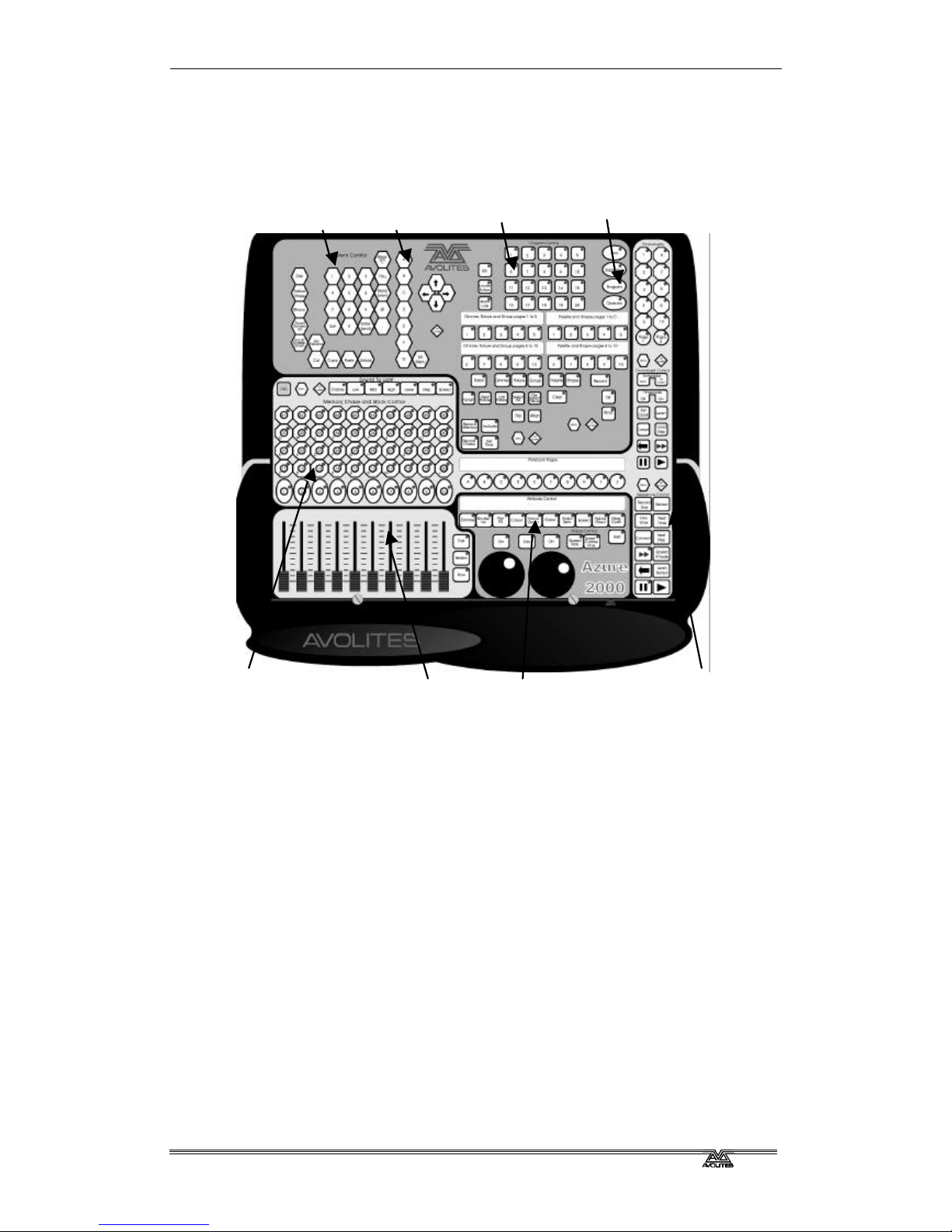
1.2 Finding your way about on the Azure 2000
The controls on the Azure are grouped together so that all the controls you
need to carry out each function are near to each other.
?? The System and menu buttons are used when you are setting up the
console, and to enter numeric values.
?? The menu softkeys are used to select one of the options from the
menus shown on the VGA display.
?? The fixture selection buttons allow you to select which fixtures or
dimmer channels you want to control, and also lets you set up the
fixtures and select preset positions, colours, gobos and shapes.
?? The desk mode buttons set the operational mode of the console.
?? The playback buttons control memories and are ideal for strobe or
shutter chases; 40 buttons are available on each page.
?? The playback faders allow intensity control of a further 10 memories.
To the right of the playback buttons are 10 playback page buttons,
giving a total of 500 playbacks.
?? The fixture control buttons and wheels allow you to control the
fixtures you have selected.
?? The environment and sequence control area is used for control of
chases, timed shows, and environments.
Playback faders
System and
menu buttons
Fixture selection Desk mode
Fixture control
Playback buttons
Environment and
sequence control
Menu softkeys
Page 9
Fehler! Formatvorlage nicht definiert.. Fehler! Formatvorlage nicht definiert. - Page 3
AZUREM2.DOC 18.03.1999 12:40
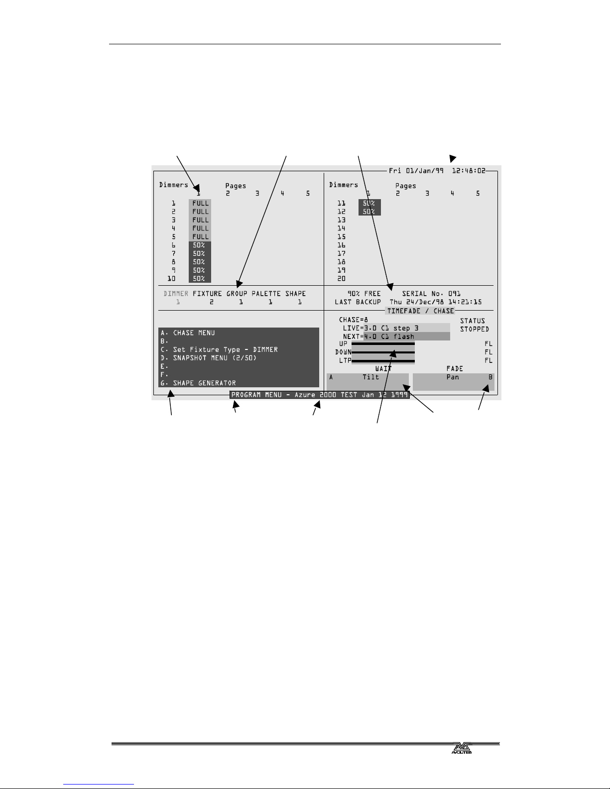
The VGA display shows everything which is going on. There are various
different screens you can display, by pressing the On Screen button in the
area you want to look at. Each control area on the Azure has its own On
Screen button. The picture below shows you a typical VGA display.
The bottom half of the display usually remains the same whatever the
display mode. The softkey options are shown on the bottom left. The chase
information is shown on the right. The current function of the two wheels
is shown on the bottom right.
If the Azure has anything to tell you, it will display the message on the
bottom line of the screen (where the software version number is on the
above screen).
When you are selecting items from a list (such as shapes or colour values),
the list appears in the bottom right hand corner of the screen.
The top part of the display varies depending on the display mode, which
you can choose by pressing the various On Screen buttons on the Azure.
The possible modes are System, Channel Output, Shape Output,
Environment, Chase Times, and Memories.
Today’s date and time
Current operation
(this is the Dimmer output page)
Name of menu Azure software
version &
message
window
Menu options
(select these
using the A-G
menu softkeys)
Information
about the desk
Function of
left wheel
Function of
right wheel
Current chase
information
Current page
of dimmers,
groups etc.
Page 10

Page 4 - Fehler! Formatvorlage nicht definiert.. Fehler! Formatvorlage nicht definiert.
AZUREM2.DOC 18.03.1999 12:40
1.3 The What Am I button
The Azure has an on-line help system, which can be very useful if you
want to know what a specific button does. To use it, just press the What
Am I button (just to the left of the Avolites logo at the top of the console),
followed by the button you want to know about. The VGA display will show
you the help topic on that button. To go back to normal, press Exit or
What Am I again.
1.4 What next?
The rest of this part of the manual is a tutorial. If you have never used an
Avolites console before, by working through the rest of the tutorial section
you should be able to get the Azure up and running, and be well on the
way to programming and running a show with it.
The tutorial is organised in the order you’ll need to do things to get the
console set up and working, so try to work through it in sequence.
If you are a seasoned Avolites user, you’ll find the Azure works much like
its bigger brothers. You might find the tutorials useful, and if there is
anything specific you need to know, just look in the appropriate part of the
Reference Manual. The Reference section is in the same order as the
Tutorial section, to make it easier to move between the two.
If you are new to intelligent lighting, or even new to lighting altogether,
you might like to read chapter 10, “Introduction to intelligent lighting”.
This explains the concepts behind digital control of lighting and will help
you to understand what we are going on about in the rest of the manual.
There is also a Glossary at the end of the Reference Manual which explains
some of the obscure lighting words we have used in the manual.
Page 11
Fehler! Formatvorlage nicht definiert.. Fehler! Formatvorlage nicht definiert. - Page 5
AZUREM2.DOC 18.03.1999 12:40
CHAPTER TWO
2. Patching
In this chapter: how to set up the Azure to control dimmers and fixtures.
?? clearing the Azure
?? patching dimmers
?? patching moving light fixtures
?? setting addresses on the fixtures
?? backing up the Azure to disk
So, you have your fixtures and dimmers all connected up with DMX cables
and the Azure connected to the end of it. Now you need to allocate each
fixture and dimmer channel to a fixture select button on the Azure, so that
you can tell it which of the fixtures or dimmers you want to control at any
time. The fixture select button is sometimes called a handle, because you
use it to take control of the fixture.
You also need to tell the Azure what type of fixtures you are using. When
you have entered this information, the Azure can tell you what addresses
to set on your fixtures and dimmers to match the settings it is using.
This setup process is called Patching.
You can patch up to 200 fixtures and 200 dimmer channels on the Azure.
There are 10 “pages” of 20 fixtures or dimmers.
The Azure controls dimmers and fixtures slightly differently, so we will look
at each in turn. But first…
2.1 Clearing the Azure
Unless the Azure is brand new, it’s a good idea to clear the memory before
you start a new setup. This ensures that you won’t get confused by any
peculiar settings left by the previous user.
2.1.1 Clearing the Azure
? ? Press the Supervisor button
? ? Enter the PIN code if necessary
? ? Select option F “Wipeall”.
? ? Press F again to confirm.
The Azure is now pristine and new, and ready for you to
start patching.
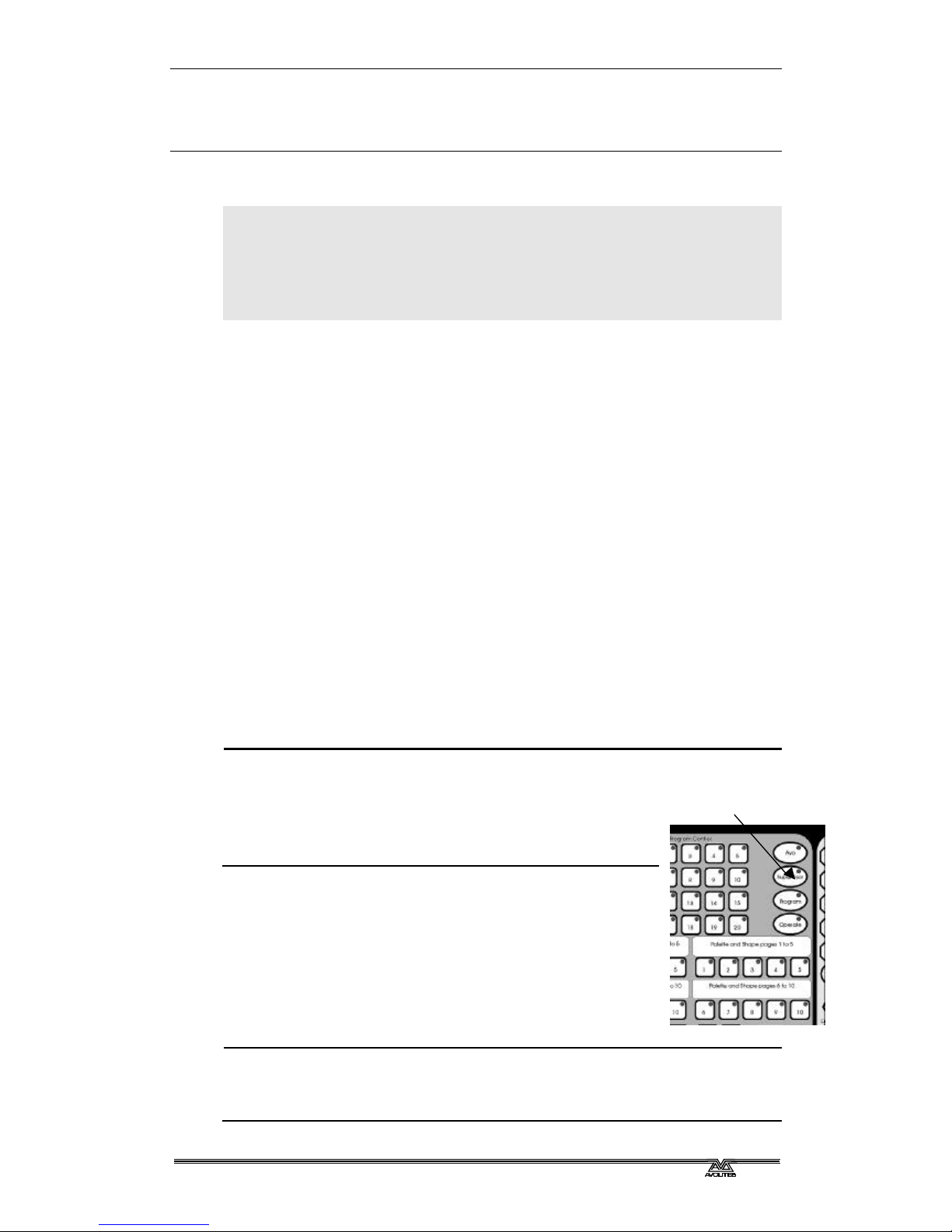
When you turn the Azure on, it always starts in Operate
mode. All you can do in this mode is play back memories.
To change anything, you need to be in Program mode.
The rest of this manual assumes you are in Program
mode.
2.1.2 Setting program mode
? ? Press the Program button
? ? Enter the PIN code if necessary
Desk mode buttons
Page 12
Page 6 - Fehler! Formatvorlage nicht definiert.. Fehler! Formatvorlage nicht definiert.
AZUREM2.DOC 18.03.1999 12:40
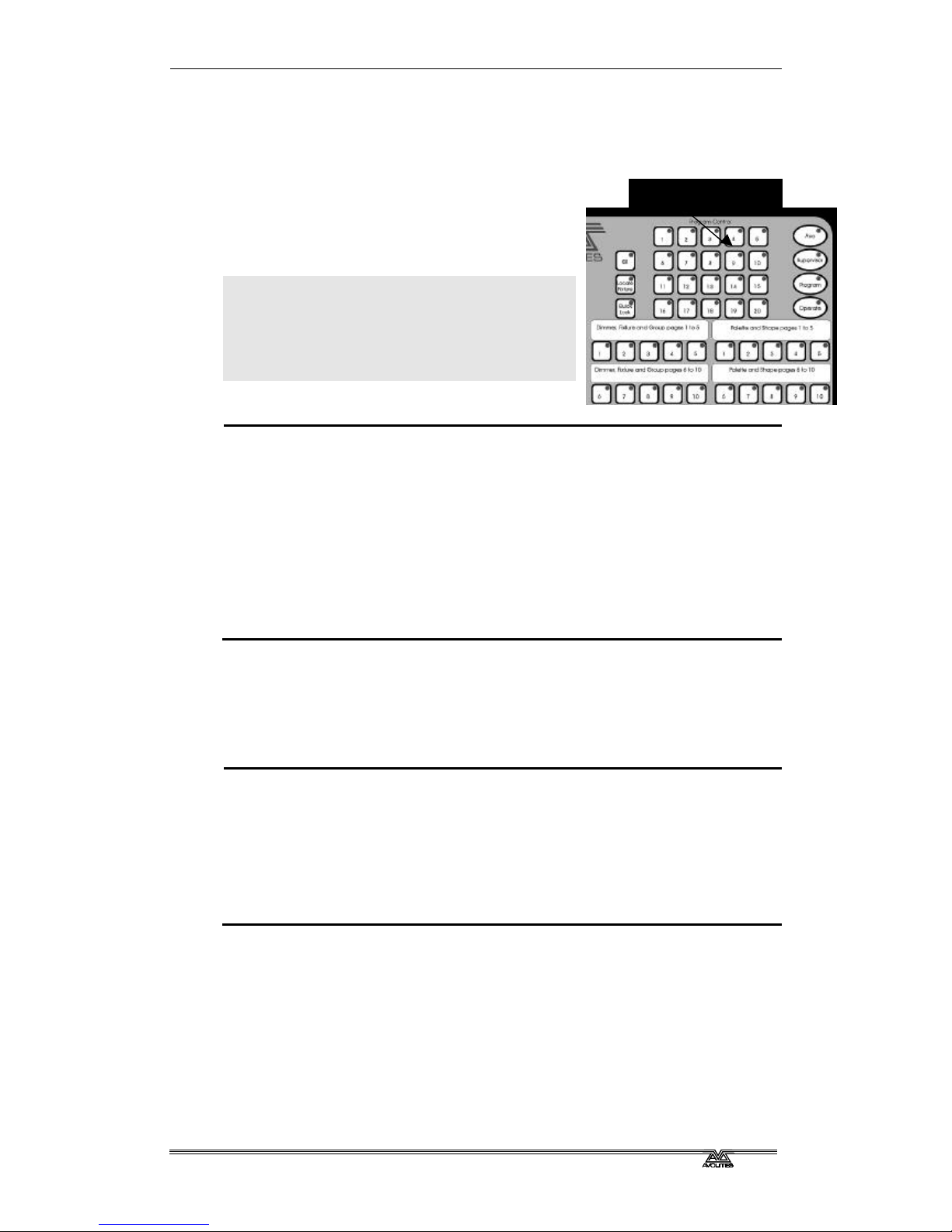
2.2 Patching dimmers
Each dimmer channel you want to use is allocated to one of the fixture
select buttons. Then, when you want to control the dimmer channel, you
simply use the button to select it.
The simplest way to patch is to have some
pages just for dimmer channels and other
pages just for fixtures, so that’s the way we
will start off.
Note: If your total number of dimmer
channels and fixtures is more than 200,
you can mix them on the same page as
well. This is called “overlay patching”
and is described in the reference
manual.
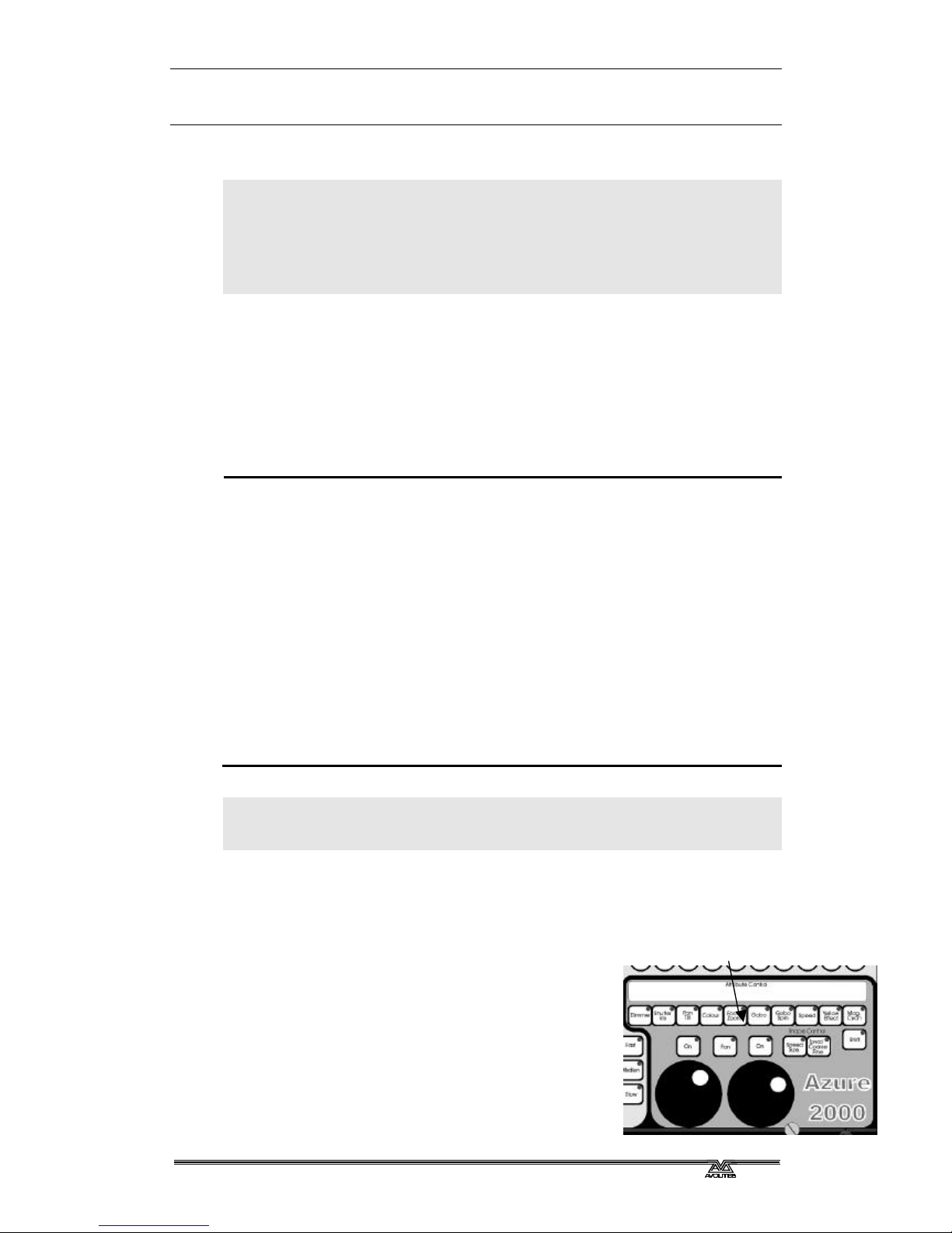
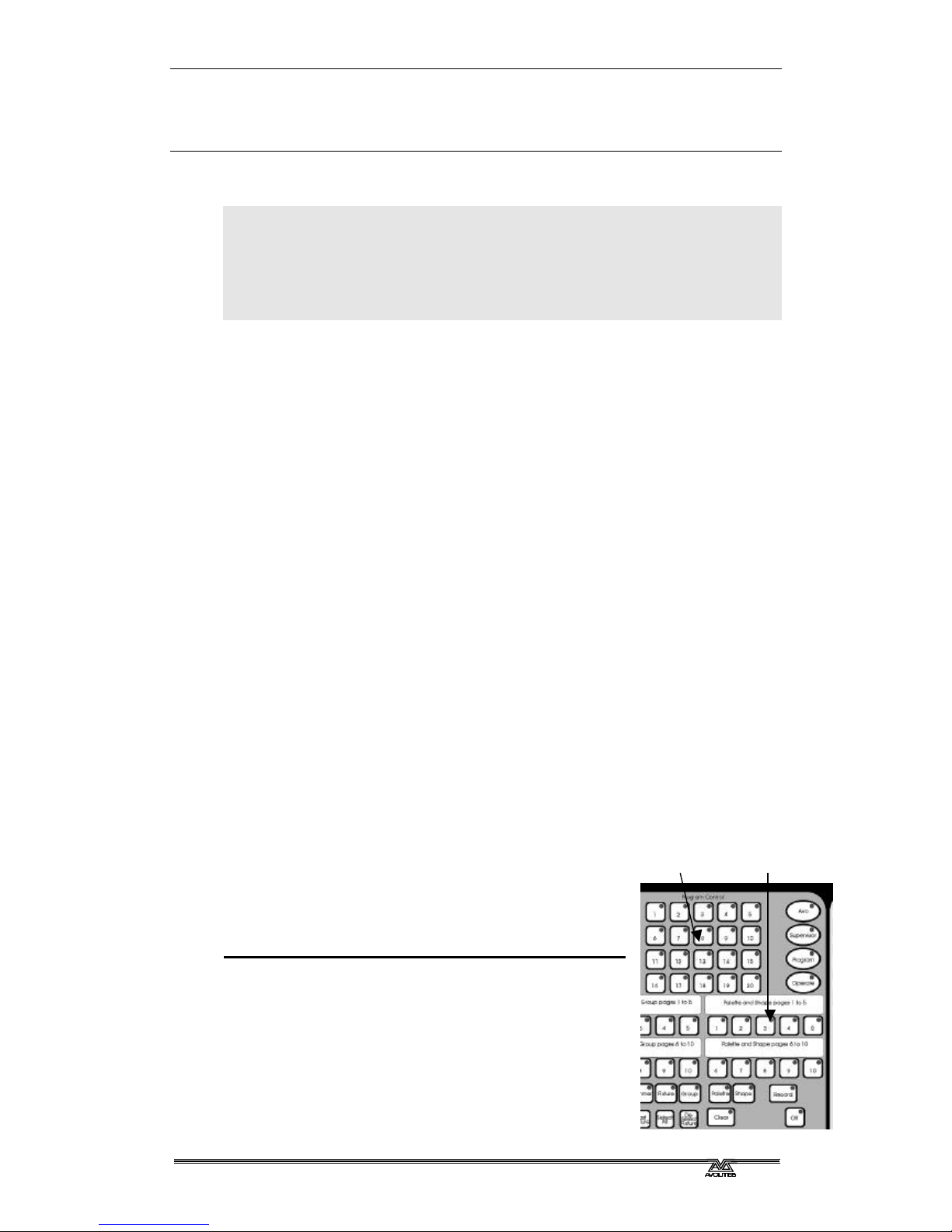
2.2.1 Patching dimmer channels
? ? Press Patch
? ? Press Dimmer
? ? Select Dimmer/Fixture page 1
? ? The Azure will start at DMX address 001 (shown on the bottom line of
the display). You can change this using the numeric keypad.
? ? Press one of the fixture select buttons. The button you press will then
be used to control the dimmer at the DMX address shown.
? ? The Azure will update the DMX address to the next channel, so you
can press another button to patch the next dimmer.
If you have lots of dimmers to patch, there are some quicker ways. If you
just want to patch dimmers 1-20 on to buttons 1-20, you can do it this
way.
2.2.2 Patching a range of dimmers to buttons
? ? Enter Dimmer Patch mode and select the page you want to use
? ? Enter the DMX channel you want the range to start at, if it’s different
to the one the Azure is displaying
? ? Hold down the first button to be patched
? ? Press the last button
? ? Each button will be allocated sequentially to a dimmer channel
You can also patch more than one dimmer channel on the same button.
This can be useful when you have several lights on different dimmer
channels, but you always want to control them together. For example, if
you have lit an area with several spots and you just want to use one
button to control all the lights on that area, this is a good way to do that.
Fixture select buttons
Page 13
Fehler! Formatvorlage nicht definiert.. Fehler! Formatvorlage nicht definiert. - Page 7
AZUREM2.DOC 18.03.1999 12:40
2.2.3 Patching several dimmers to the same button
? ? Enter Dimmer Patch mode and select the page you want to use
? ? Using the numeric keypad, enter the DMX address of the first dimmer
channel to be patched
? ? Press the button you want to use to patch the first dimmer
? ? Using the numeric keypad, enter the DMX address of the next dimmer
channel to be patched
? ? Press the button again
You can repeat this procedure to patch as many dimmers as you like on to
one control button.
The display shows you which channels you have patched so far.
2.3 Patching moving light fixtures
Moving light fixtures are slightly different to dimmers because they have
more attributes to control, such as pan, tilt, colour etc., where a dimmer
channel just has intensity. When you patch a fixture, you will see on the
display that it occupies a block of DMX channels rather than just one.
However, the principle is still the same.
The Azure has personality files for most lighting fixtures in the known
universe. If your console has 1999 software, they should be pre-loaded
into the console. If not, you can use the personality disk which came with
the console.
Note: To use the internal personality files, make sure there is no disk in
the disk drive.
2.3.1 Patching a fixture
? ? Make sure there is no disk in the disk drive
? ? Press Patch
? ? Press Fixture
? ? The display will show “Please wait … reading files” on the bottom line.
? ? A list of known manufacturers will appear after a pause. If not, insert
the personality disk and start again.
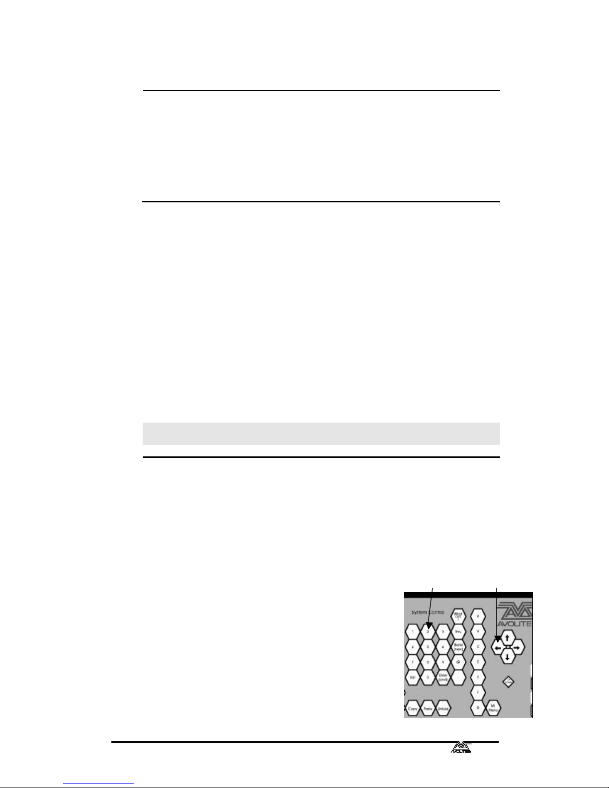
? ? Use the cursor arrows to select the manufacturer of your fixture.
? ? Press Enter. The display will show all available
fixtures for that manufacturer.
? ? Use the cursor arrows to select the correct
fixture.
? ? Press Enter.
? ? The Azure will ask “Automatically create
palettes?”.
? ? Press Softkey A for Yes. (This is explained later)
Cursor arrows
Numeric keypad
Page 14
Page 8 - Fehler! Formatvorlage nicht definiert.. Fehler! Formatvorlage nicht definiert.
AZUREM2.DOC 18.03.1999 12:40
? ? The Azure will offer you the first free DMX address. You can change
this using the numeric keypad if you want your first fixture at a
different address.
? ? Select Dimmer/Fixture page 2 (or another unused page)
? ? Press Fixture Select button 1 to patch the fixture you have selected.
? ? The display will show the block of channels occupied by the fixture.
You can continue to patch this type of fixture at the next free DMX address
by pressing the next fixture select button you want to use. You can also
patch a range of fixtures by holding down the first button in the range and
pressing the last button, as with dimmers.
If you have several different types of fixtures, you can change the type of
fixture to be patched very easily.
2.3.2 To change the fixture type
? ? Press softkey A (“Select another fixture”)
? ? Choose a manufacturer
? ? Choose a fixture
? ? Patch as before
Note: The automatic palettes you can load contain a selection of position,
colour and gobo settings. You can call back settings from the
palettes when programming rather than having to set up your own,
allowing you to select, for example, “Yellow” or “Blue” instead of
setting up the value using the wheels. You can’t load the automatic
palettes later (though you can define your own).
2.4 Addressing your fixtures to match the Azure
Once you have told the Azure where to allocate all your dimmers and
fixtures, you need to go round the actual lights and set the DMX address
to match the Azure.
The Azure can tell you the DMX address it is using for each fixture, and in
some cases can show you how to set the dip switches on the fixture. It’s
usually easiest to write down the addresses for all the fixtures, then go
and set them.
2.4.1 Displaying the DMX address for fixtures
? ? Press the On Screen button below the cursor arrows
? ? Select the page of fixtures you want to look at
? ? Press a fixture select button
? ? The screen will show the fixture type and DMX line and address (e.g.
A24 is address 24 on DMX line A).
? ? The dip switch settings may also be shown if the fixture personality
includes this information. Otherwise you will have to work it out.
? ? You can also select Softkey B, “Patch by Fixture” to display a list of the
fixtures and DMX addresses allocated to them.
Page 15

Fehler! Formatvorlage nicht definiert.. Fehler! Formatvorlage nicht definiert. - Page 9
AZUREM2.DOC 18.03.1999 12:40
2.5 Changing what you have done
If you need to change the patching you have done, you can re-patch a
fixture to a different DMX address. You can also patch a fixture onto a
different select button, but this loses any programming for the fixture.
How to change the patching is described in the reference manual.
2.6 Completing the patch
When you have patched all your dimmers and fixtures, press the Exit
button on the numeric keypad to go back to normal mode. You have now
completed the setting up of the lighting system, and it’s time to get to
work on programming a show. But there’s one important thing to do first…
2.7 Backing up the Azure to disk
The Azure has a built in disk drive which allows you to save everything you
have done. You should get into the habit of saving your show regularly to
guard against that unexpected moment when the worst happens.
It only takes a minute or so to save the contents of the Azure to disk. You
can then reload it if you mess up the show by accidentally changing
something, or if some local hoodlum steals the console you can load the
show into a replacement Azure or Pearl 2000.
2.7.1 Backing up the Azure to disk
? ? Press the Disk button in the top left hand corner of the Azure
? ? Insert a blank formatted 1.44M disk into the disk drive.
? ? Select softkey B, “Save show to disk”.
? ? The Azure will save your current show onto the disk. The VGA display
will tell you when the Azure has finished.
? ? If you need to reload the show, use softkey A, “Load show from disk”.
Page 16

Page 10 - Fehler! Formatvorlage nicht definiert.. Fehler! Formatvorlage nicht definiert.
AZUREM2.DOC 18.03.1999 12:40
Page 17
Fehler! Formatvorlage nicht definiert.. Fehler! Formatvorlage nicht definiert. - Page 11
AZUREM2.DOC 18.03.1999 12:40
Attribute buttons
CHAPTER THREE
3. Controlling dimmers and fixtures
In this chapter: how to control dimmers and fixtures manually.
?? selecting fixtures and dimmers
?? changing attributes
?? entering dimmer levels numerically
?? using and creating palettes
?? using and creating groups
Having patched all the dimmers and fixtures you want to use, you are
ready to start operating them. This chapter explains how you do this.
3.1 Selecting what you want to control
The first thing you have to do is to select the fixtures or dimmer channels
that you want to control. You can select fixtures or dimmers individually,
or several at once.
3.1.1 Selecting fixtures or dimmers
? ? Press the Page button for the page of fixtures you want to use
? ? If there are both dimmers and fixtures on the page, press the Fixture
or Dimmer button to select which type you want.
? ? Press the buttons for the fixtures/dimmers you want to control.
? ? Fixtures/dimmers which are selected (you have control of) are shown
in dark blue on the VGA display.
? ? If you select a fixture/dimmer you don't want, press the button again
to deselect it.
? ? You can press “Locate Fixture” to position the selected fixtures at a
“home” position with the light on, so you can see where they are.
Dimmer channels are set to 50%.
? ? You can select a range of fixtures by holding down the button for the
first fixture in the range, then pressing the button for the last fixture.
Note: When you press the page button, the fixture buttons will light up to
show you which buttons on that page are patched to fixtures or
dimmers.
If you select a range of fixtures, or a group, the Last Fixture and Next
Fixture buttons allow you to go through the fixtures in the range selecting
them one at a time. The Highlight button will turn on the dimmer of the
fixture that is currently selected. The Select All button selects the whole
range of fixtures again.
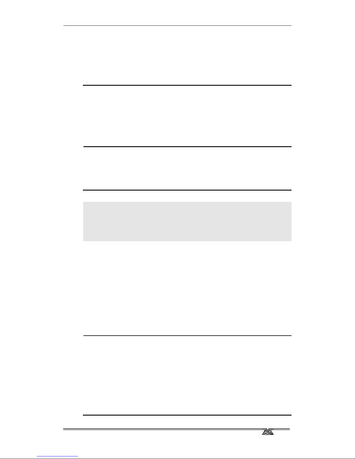
3.2 Changing attributes of fixtures
Having selected the fixtures you want to control,
you then need to select the attributes of that fixture
that you want to change.
The attributes are selected using the buttons on the
lower right of the Azure just above the wheels. The
attributes you can control will vary depending on
Page 18

Page 12 - Fehler! Formatvorlage nicht definiert.. Fehler! Formatvorlage nicht definiert.
AZUREM2.DOC 18.03.1999 12:40
the type of fixture you are using. For dimmer channels, you can only
change the intensity. For scans, you can control the pan, tilt, colour, gobo
and other functions.
3.2.1 Controlling intensity
? ? Select some dimmer channels or fixtures
? ? Press the Dimmer attribute button
? ? Control the dimmer intensity using the left hand wheel
? ? The intensity value is shown on the VGA display
Note: Some fixtures don’t have an intensity function so this operation will
not have any effect. Lamp on/off is usually controlled by the Gobo
function on these units.
Any other attribute can be controlled by pressing the appropriate button.
The VGA display will show which functions the left and right wheels are
going to control.
3.2.2 Controlling pan and tilt of a fixture
? ? Select some fixtures to control
? ? Press the Pan and Tilt attribute button.
? ? Control the pan using the left hand wheel and the tilt using the right
hand wheel.
? ? The pan and tilt values are shown on the bottom right hand of the VGA
display
Note: Once you have changed any attributes, all the fixtures will be
automatically deselected the next time you press a fixture select
button.
3.3 Entering dimmer levels numerically
You can control dimmers using the numeric keypad as you would on a
theatrical lighting desk. This method of setting dimmer levels can be faster
when plotting a scene than using the select buttons and the wheels. You
enter the dimmer number, then the “@” (at) key, then the level.
3.3.1 Entering dimmer levels
? ? On the numeric keypad, enter the dimmer channel number
? ? Press the @ button
? ? Enter the value to be set as 0 – 9. You can enter a decimal point and
another number if you want more accurate level control.
? ? Press @ again instead of a number (or Softkey D) for 100%
? ? The channel you entered will be set to the level you entered.
The softkeys offer you a few more options such as set to 100%, up by 5%,
down by 5%. These options are shown on the VGA display.
You can also set multiple channels to the same level using the “thru”
Page 19
Fehler! Formatvorlage nicht definiert.. Fehler! Formatvorlage nicht definiert. - Page 13
AZUREM2.DOC 18.03.1999 12:40
button. Enter first channel, “thru”, last channel, “@”, level.
3.3.2 Entering multiple dimmer levels
? ? On the numeric keypad, enter the first dimmer channel number of the
range
? ? Press the Thru button
? ? Enter the last dimmer channel number of the range
? ? Enter the value to be set as 0 – 10. You can enter a decimal point if
you want more accurate level control.
? ? The channels you entered will all be set to the level you entered.
You can also directly enter attribute values for fixtures. The reference
manual tells you how.
3.4 Using palettes
When you are controlling attributes which are
continuously variable such as pan, tilt, and
colour, it can speed things up if you can
instantly call back a position such as centre
stage, or a particular colour like red, blue etc.
If you’ve got different types of fixtures, to get
the same colour on each fixture might mean
setting different values for each type of fixture.
The Azure has pages of preset values, called
“palettes”, which you can use to store attribute
settings which you use a lot. The Azure loads 10
pre-programmed positions, 10 colours and 10
gobos each on a separate page when you patch
a fixture (unless you tell it not to).
This means that if for example you want all your fixtures to go Red, you
just have to select “Red” from the colour page of the palette. The Azure
knows the values to send to each fixture to get red light out of it.
3.4.1 Using palettes
? ? Select the fixtures you want to control
? ? Press the Palette button
? ? Select the page of palettes you want to use. The VGA display will show
the contents of each page.
? ? Press one of the fixture select buttons to use one of the palette values.
The value will be set to all the fixtures which are selected.
You can also store your own palette values of positions, colours and so on
that you use regularly. The reference manual gives more information on
how to do this.
When you use a palette value, the Azure remembers the palette entry you
used rather than the actual values you used. This can be very handy when
you are touring a show, if you use palette entries to program the show.
When the venue is a different shape, you only need to redefine a few
standard palette positions rather than having to reprogram the whole
Palette pages Palette values
Page 20
Page 14 - Fehler! Formatvorlage nicht definiert.. Fehler! Formatvorlage nicht definiert.
AZUREM2.DOC 18.03.1999 12:40
show. All the memories which used the palette positions will then use the
new positions.
Note: The Azure may sometimes call palettes “focuses” or “preset
focuses”. This is the term used for a palette on other Avolites
consoles. The meaning is the same.
3.5 Using groups
The Azure allows you to put fixtures or dimmer channels into groups. This
can speed up the process of selecting fixtures or dimmers. If you have
several different types of fixture, for example, you can make a group for
each type of fixture. You can then select all the fixtures just by pressing
one button.
3.5.1 Making a group
? ? Select the fixtures or dimmer channels you want to put into the group
? ? Press the Record button
? ? Press the Group button
? ? Select the page of groups you want to use. The VGA display will show
the contents of each page.
? ? Press one of the fixture select buttons to store the group on that
button.
Once you have created a group, you can then instantly select all the
fixtures in the group simply by pressing Group, then a group button.
3.5.2 Selecting a group of fixtures
? ? Press the Group button
? ? Select the page of groups you want to use. The VGA display will show
the contents of each page.
? ? Press one of the fixture select buttons to select the group on that
button.
You can enter a name for groups you have created to help you remember
which fixtures are in the group. The reference manual tells you how to do
this.
Page 21
Fehler! Formatvorlage nicht definiert.. Fehler! Formatvorlage nicht definiert. - Page 15
AZUREM2.DOC 18.03.1999 12:40
CHAPTER FOUR
4. Using shapes
In this chapter: how to use the shape generator
?? selecting a shape
?? positioning
?? setting size and speed
?? coarse and fine spread
?? also Fan mode
The Azure, in common with other Avolites consoles, has a shape
generator. This allows you to quickly create exciting light shows using lots
of movement and changes, with the minimum of programming.
There are a large number of pre-programmed shapes available, which can
be used on the position, colour, gobo, dimmer, or iris of a fixture. You can
control the size, speed and positioning of the shape, and how the shape is
allocated across a range of fixtures. You can also define your own shapes.
To understand how shapes work and how they can be spread across
multiple fixtures, it’s best to set up at least four fixtures next to each
other. Once you have mastered the basics, you can try some more
interesting arrangements.
4.1 How shapes work
A shape is a pre-programmed movement sequence which usually repeats
over and over again. Typical shapes are circles, spirals, squares, etc. There
are also random shapes, which do not repeat.
When you apply a shape, it works on the current settings of the fixture. So
if you apply a circle to the pan and tilt attributes of a fixture, the centre of
the circle will be at the current pan and tilt position. You can change the
size of the circle, and the speed of the circle. By moving the pan and tilt
position of the fixture, you can move the whole shape around the stage.
Shapes can be applied to other attributes of a fixture, not just pan and tilt.
You can use them to create colour changes, gobo changes, iris changes
and a variety of other attributes. Each shape is designed to modify one
particular attribute.
4.2 Selecting a shape
Selecting a shape is very similar to selecting a value
from a palette. When you choose a shape, it will be
applied to all selected fixtures.
4.2.1 Selecting a shape
? ? Select the fixtures you want to apply the shape to
? ? Press Locate Fixtures to turn on the fixtures and
move them to a central position
? ? Press the Shape button
Shape pages Shapes
Page 22
Page 16 - Fehler! Formatvorlage nicht definiert.. Fehler! Formatvorlage nicht definiert.
AZUREM2.DOC 18.03.1999 12:40
? ? Select the page of shapes you want to use. The VGA display will show
the contents of each page of shapes.
? ? Press one of the fixture select buttons to select a shape. The shape will
be applied to all selected fixtures.
The shape will start based on the current setting of the attribute.
4.3 Changing the size and speed of a shape
It is easy to change the size and speed of a shape after it has first been
selected.
4.3.1 Changing the size and speed of a shape
? ? Press the Size / Speed button just above the wheels
? ? Control the size of the shape using the left hand wheel
? ? Control the speed of the shape using the right hand wheel
? ? The size and speed is shown on the VGA display.
The minimum size is zero. Obviously, you won’t see the shape, and the
fixture will resume its previous settings. The minimum speed is Stop.
Again, you will not see the shape, though it will offset the positioning of
the fixture.
4.4 Changing the positioning of a shape
A shape is based on the current settings of the fixture. For a pan/tilt
shape, this means that the movements will be centred around the current
position of the fixture. For a colour shape, the colour changes will be
centred round the current colour of the fixture.
4.4.1 Changing the positioning of a shape
? ? Select the fixtures you want to change
? ? Select the attributes of the fixture you want to change
? ? Set the attributes using the wheels. It’s easiest to reduce the Size of
the shape to zero while you are setting the attributes, otherwise
everything keeps moving and it is difficult to tell what is happening.
? ? Set the Size of the shape back to where you want it.
4.5 How a shape works across multiple fixtures
Shapes get more interesting (and look more impressive) when you apply
them to multiple fixtures. The Azure lets you set how a shape is spread
across several fixtures.
In the case of a circle, this can vary from all fixtures moving identically (a
spread of 1), fixtures working in pairs (a spread of 2) through to all
fixtures being distributed evenly through the shape, so the first fixture is
just starting the shape as the last one finishes (an Even spread).
You can also set the Fine Spread value, which introduces a slight offset
into the timing of the shape across each fixture.
Page 23
Fehler! Formatvorlage nicht definiert.. Fehler! Formatvorlage nicht definiert. - Page 17
AZUREM2.DOC 18.03.1999 12:40
4.5.1 Changing the spread of a shape
? ? Press the Spread Fine/Coarse button
? ? Set the coarse spread using the right hand wheel. The minimum is 1
(all fixtures the same). The maximum is Even (the shape spread
evenly across the fixtures).
? ? Set the fine spread using the left hand wheel.
To start with, you will find it easier to keep the Fine Spread set to zero,
and work with the Coarse Spread setting, or everything will get confusing.
Note: The order in which you select the fixtures determines how the
shapes are applied; the “first” fixture is the one you select first and
the “last” fixture is the one you select last.
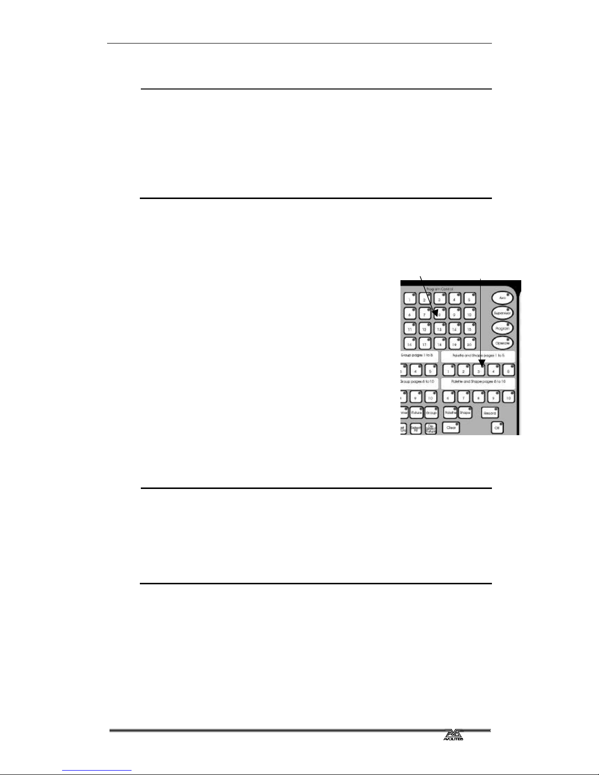
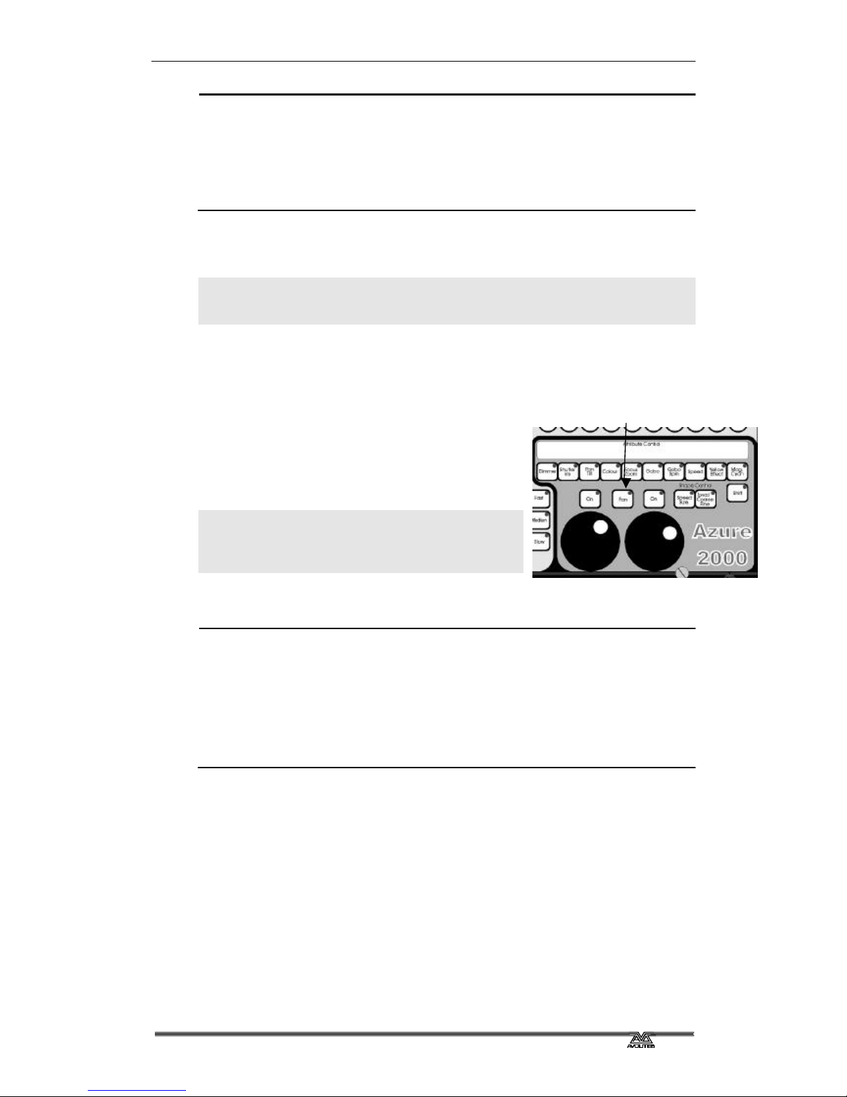
4.6 Fan mode
Fan mode is not really anything to do with shapes, but we have put it in
this chapter because it works in a similar way.
Fan mode automatically spreads out a selected
range of fixtures to produce a fan of light
beams. The first and last fixtures of the range
are affected most, and the central fixtures are
affected least. The amount of fan can be set
using the wheels.
Note: As with shapes, the order in which you
select the fixtures sets how the fan effect
works. The fixtures you select first and
last will be the ones which change most.
The fan effect, while normally used on pan or tilt attributes, can be applied
to any attribute.
4.6.1 Fanning out a range of fixtures
? ? Select the range of fixtures you want to fan
? ? Select the attribute to fan (pan, tilt, colour etc)
? ? Press the Fan button
? ? Set the amount of fan using the wheels
? ? The VGA display shows which attribute is being controlled by each
wheel
You will be able to see the effect of fan mode best if you have a row of at
least 4 fixtures. If you have an odd number of fixtures, the central fixture
will not move in fan mode.
Fan mode button
Page 24

Page 18 - Fehler! Formatvorlage nicht definiert.. Fehler! Formatvorlage nicht definiert.
AZUREM2.DOC 18.03.1999 12:40
Page 25

Fehler! Formatvorlage nicht definiert.. Fehler! Formatvorlage nicht definiert. - Page 19
AZUREM2.DOC 18.03.1999 12:40
CHAPTER FIVE
5. Recording and playing back memories
In this chapter: how to record memories into the playback buttons
?? explanation of HTP and LTP channels
?? how the programmer works
?? record by fixture or by channel
?? recording and playing back memories
?? memory pages
?? latch and flash mode
?? labelling and displaying memories
?? setting times for memories
?? cut, copy and paste
?? the include function
?? editing memories
So, you now know how to control your dimmers and fixtures, and how to
use the shape generator. This chapter tells you how to record the
wonderful effects you have created so that you can recall them at the
touch of a button.
Before we get onto the details of recording memories, there are a couple of
general things about how the Azure works. The first thing to understand is
what happens when you play back more than one memory at a time, and
the operation of HTP and LTP channels. It’s important to understand this
before going on.
5.1 What are HTP and LTP channels?
The Azure treats channels which control intensity differently from other
moving light control channels. When only one memory is turned on, there
is no problem. But if two or more memories are turned on together, or if
you fade out a memory, the Azure needs to know how to output the levels
from the memories.
Dimmer or intensity channels work on the principle of “highest takes
precedence” (HTP). This means that if an HTP channel is turned on in
several memories, the highest level will be output. When you fade a
memory, the HTP channels fade out.
Moving light channels work on the principle of “latest takes precedence”
(LTP). This means that the latest change takes over from any other values,
so the most recent memory to be turned on is the one which is output.
When you fade in a memory, LTP channels do not usually fade, but come
on at their full values, and stay there until another value is set.
The fixture personality file tells the Azure which channels of a fixture are
HTP and which are LTP. Normally, only dimmer attributes are HTP, and
everything else is LTP.
5.2 How the Azure works when programming
The Azure remembers which fixtures you have changed, and which you
have not. Fixtures you have changed are stored in “the programmer”.
When you record a memory, only the settings in the programmer (i.e. the
ones you have changed) are stored in the memory.
Page 26
Page 20 - Fehler! Formatvorlage nicht definiert.. Fehler! Formatvorlage nicht definiert.
AZUREM2.DOC 18.03.1999 12:40
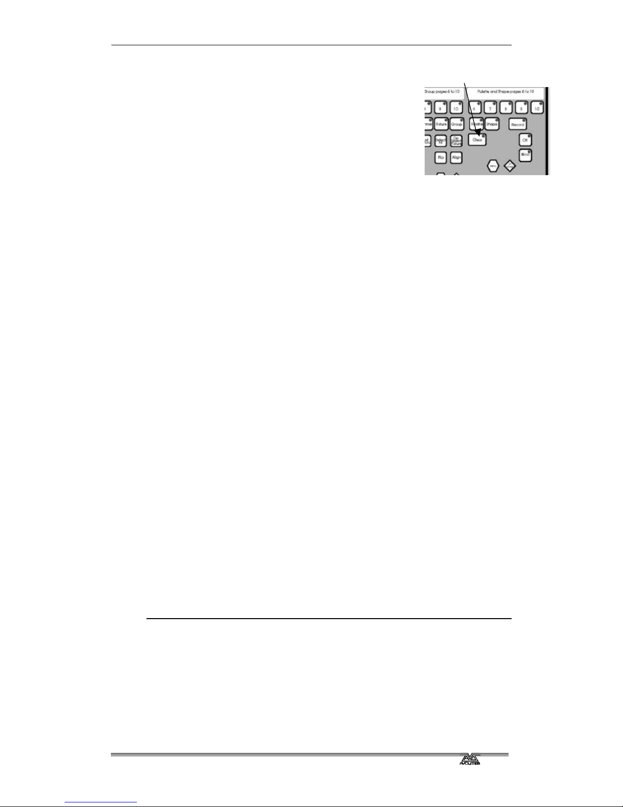
When you press Clear, all fixtures are cleared from the
programmer. You should get into the habit of pressing
Clear before you start to program a memory, or you
can end up recording fixtures you don’t want. You also
need to press Clear when you finish programming,
because any functions in the programmer will override
playbacks.
You can tell when there is something stored in the
programmer because the Clear button will flash.
5.3 “Record by fixture” and “record by channel” modes
Normally the Azure records all the attributes of any fixture you change.
However, the Azure also has a more selective mode of operation. You can
choose the mode by pressing the Set User Preferences button.
?? Mode 1: Record by fixture. This is the normal mode of the Azure. It
means that when you record a memory, all attributes of every fixture
that you have changed are recorded in the memory. So if you change
only the position of a fixture, the colour, gobo, intensity and all other
attributes of that fixture are recorded as well. This is useful because
you know that when you recall the memory, it will look exactly as it did
when you saved it. However, it can be slightly inflexible if you want to
combine memories.
?? Mode 2: Record by channel. This means that only attributes you have
changed are recorded in the memory. So if you change the position of
a fixture, only the position is recorded. When you recall the memory,
the colour, gobo etc will remain as they were last set. This means you
can set the position from one memory, and the colour from another
memory, allowing more variety when you are running a show.
You can tell the attributes which are in the programmer by looking at the
VGA display. Attributes in the programmer are shown with a light blue
(cyan) background. Attributes not in the programmer are on the normal
grey background.
Turning on a memory does not place the values from the memory in the
programmer (the Include function lets you do this, see page 23). The
Locate Fixture button does not place any values in the programmer either.
When you record a memory, HTP channels are always recorded at their
current value. The programmer only works with LTP channels.
5.4 Recording a memory
So now that is all out in the open, let’s record a memory. The Azure has 10
pages of 50 memories. The bottom 10 memories of each page are replayed
using the faders. The rest are replayed using buttons.
5.4.1 Recording a memory
? ? Press Clear to clear the programmer. This ensures that you are
starting with a clean slate.
? ? Set up a nice effect using the fixtures. You can include shapes in a
memory if you want. Remember! Only the fixtures you have changed
will be recorded in the memory.
? ? Press Record Memory.
Clear button
Page 27
Fehler! Formatvorlage nicht definiert.. Fehler! Formatvorlage nicht definiert. - Page 21
AZUREM2.DOC 18.03.1999 12:40
? ? Memories which are empty will flash. You can change the playback
page if you want.
? ? Press one of the flashing buttons to save the memory. (Buttons 1-10
will allocate the memory to a fader).
? ? Press Clear to clear the programmer.
5.5 Playing back a memory
Playing back a memory is very simple. Just press the button, or raise the
fader. (Make sure there are no values in the programmer by pressing the
Clear button, because anything in the programmer will override the
playback).
5.5.1 Playing back a memory
? ? Select the playback page you want.
? ? Press the playback button, or raise the fader if it is one of the
playbacks in the 1-10 range.
? ? To stop the memory, press the button again or lower the fader.
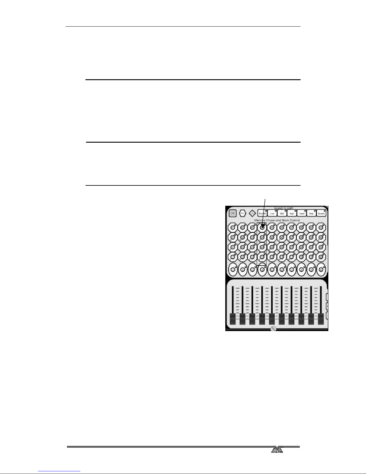
You can turn on more than one memory at
once, and the levels in each memory will
combine using the HTP and LTP rules.
However, you can only turn on one memory in
each column (the picture shows one of the
columns). If you have memory 14 turned on,
and you turn on memory 24, then memory 14
will turn off. This applies even if you change
pages. The faders work separately, so you can
turn on up to 20 playbacks at once.
If you are using a fader, all the HTP (intensity)
channels in the memory will fade up with the
fader. The LTP (movement) channels will be
set as soon as the fader leaves the zero
position.
Pressing the DBO (Dead Black Out) button
turns off all the HTP channels. You can turn off
all active memories by holding down the DBO
button and pressing Clear.
5.6 Changing playback pages
You can change pages to select another 50 memories simply by pressing
one of the playback page buttons.
If any playbacks are turned on when you change page, they remain turned
on. The light flashes on the playback button to tell you that the playback is
active on another page.
There are 2 ways to turn off a playback on a different page to the current
page. If you turn on a playback in the same column, the other playback
will turn off. Or you can change page back to the original page.
Playbacks in one column
Page 28
Page 22 - Fehler! Formatvorlage nicht definiert.. Fehler! Formatvorlage nicht definiert.
AZUREM2.DOC 18.03.1999 12:40
5.7 Latch or flash mode
You can set each of the 11-50 playbacks to latch (push to turn on, push
again to turn off) or to flash (playback is on only while the button is held
down). Flash mode can be useful for strobing playbacks or audience
blinders, or any playback you only want to run momentarily. The 1-10
buttons are always flash buttons.
5.7.1 Setting latch or flash
? ? Press the Menu button next to the DBO button.
? ? Press Softkey A (Latch or Flash).
? ? Press the 11-50 playback button you want to set. Buttons with lights
on are in Latch mode. Buttons with lights off are in flash mode.
? ? Press Exit when you have finished.
5.8 Labelling a memory and displaying memories
The Azure allows you to label all the memories.
This can be very helpful when you are trying to
remember where you put that amazing effect
you created yesterday.
You can display the names of the memories on
the VGA display by pressing the On Screen
button next to the DBO button. The Azure
displays a screen showing all the memories in
the current page.
5.8.1 Labelling a memory
? ? Press the Input Legend button.
? ? Press the playback button you want to label.
? ? Enter the label using the letters on the playback buttons. You can also
plug in a standard PC keyboard.
? ? Press Enter to save the label.
? ? You can label another memory by pressing another button, or finish by
pressing Exit.
You can also label the playback pages, fixture groups and palettes using
this method.
When you are using the playback on-screen function, the Azure highlights
memories which are turned on in bright white text.
5.9 Setting fade times for a memory
You can set a fade in and fade out time independently for every memory.
The fades only affect HTP (intensity) channels, and are set using softkey C
for fade in and D for fade out. There is also a separate LTP timer which
allows you to set movement times, set using softkey E.
5.9.1 Setting fade times for a memory
? ? Press the Set Time button.
Playback On Screen button
Page 29

Fehler! Formatvorlage nicht definiert.. Fehler! Formatvorlage nicht definiert. - Page 23
AZUREM2.DOC 18.03.1999 12:40
? ? Press the playback button you want to set times for
? ? The VGA display shows you the times you can set.
? ? Use the cursor up-down buttons or softkeys A-F to move the cursor
bar over the times you want to set.
? ? Use the numeric keypad to enter the new time. Press Enter to save it.
? ? Press Exit when you have finished.
There are some other timing functions available as well, which you don’t
need to worry about at the moment. They are described in the reference
manual.
5.10 The Cut, Copy and Paste functions
The Cut, Copy and Paste functions work just like they do on a PC. They
enable you to delete memories, copy them and move them to another
position.
When you press Cut or Copy, then a playback button, that memory is
copied to a temporary memory. If you pressed Cut, the original memory is
deleted. If you pressed copy, it is not affected. You can then use Paste to
place a copy of the memory on another playback. You can use Paste as
many times as you like to make multiple copies of the memory.
5.10.1 Using Cut and Paste
? ? Press Cut.
? ? Press the playback button you want to cut.
? ? The memory is removed from the playback button and stored in a
temporary memory.
? ? Press Paste.
? ? Press the playback button you want to paste the copy to.
? ? The memory is stored on the new playback button. The label of the
memory is not copied.
Copy works in a similar way to cut, except that the original memory is
retained.
5.10.2 Using Copy and Paste
? ? Press Copy.
? ? Press the playback button you want to copy.
? ? The memory is copied from the playback button and stored in a
temporary memory.
? ? Press Paste.
? ? Press the playback button you want to paste the copy to.
? ? A copy of the memory is stored on the new playback button. The copy
is not linked in any way to the original memory, so changing one will
not affect the other.
5.11 The Include function
Sometimes it’s useful to be able to re-use some aspects of a memory you
Page 30

Page 24 - Fehler! Formatvorlage nicht definiert.. Fehler! Formatvorlage nicht definiert.
AZUREM2.DOC 18.03.1999 12:40
have already created in another memory. If you’ve created a really nice
combination of colours, for example, you might want to use it again in
another memory with different gobos and positions.
Normally when you play back a memory, the information is not loaded into
the programmer, so you can’t use it to make another memory. The Include
function lets you load selected parts of a memory into the programmer.
You can then use these parts in a new memory.
The Include function loads selected attributes of selected fixtures into the
programmer. So, for example, if you have a memory which contains
position, colour and gobo information for 8 fixtures, you can use the
include function to load only the colour information for 4 of the fixtures
into the programmer. You could then “include” position information from
another memory into the programmer, and build up a new memory using
information from several existing memories.
5.11.1 Using Include
? ? Select the fixtures from which you want to take settings.
? ? Press the Include button.
? ? Select the Attributes you want to include. The Dimmer attribute will
include all other attributes.
? ? Press the playback button for the memory you want to include.
? ? The selected attributes of the selected fixtures will be loaded into the
programmer.
You can Include an entire memory by ensuring no fixtures are selected
when you press Include.
If the memory you are including contains shapes, the shapes and all the
fixtures they are applied to will be loaded, whether they are selected or
not.
Include is also useful when you are programming chases, which is
described in the next section.
5.12 Editing memories
You can edit any part of a memory you have already saved simply by
making the changes and saving the new information on top of the
memory.
5.12.1 Editing a memory
? ? Press Clear to empty the programmer.
? ? Turn on the memory you want to edit, so you can see what you are
doing.
? ? Select the fixtures you want to change, and make the changes.
? ? Press Record Memory.
? ? Press the playback button for the memory you are editing to save the
changes.
The changes you have made are saved into the memory. None of the other
information in the memory is affected.
Page 31

Fehler! Formatvorlage nicht definiert.. Fehler! Formatvorlage nicht definiert. - Page 25
AZUREM2.DOC 18.03.1999 12:40
5.13 Using shapes in memories
As you would expect, any shapes you have set up will be saved as part of
the memory. If you are using Record by Channel mode, there are some
interesting possibilities.
If you have changed the position of the fixture, then the new position will
be stored in the programmer. When you recall the memory, the fixture will
start the shape at the position you set in the memory.
If you have not changed the position of a fixture, when you recall the
memory the shape will run at whatever the current position of the fixture
is. This allows you to make a “shape only” memory which overlays shapes
on the current positioning of the fixtures.
Page 32

Page 26 - Fehler! Formatvorlage nicht definiert.. Fehler! Formatvorlage nicht definiert.
AZUREM2.DOC 18.03.1999 12:40
Page 33

Fehler! Formatvorlage nicht definiert.. Fehler! Formatvorlage nicht definiert. - Page 27
AZUREM2.DOC 18.03.1999 12:40
CHAPTER SIX
6. Recording and playing back chases
In this chapter: how to record chases
?? explanation of chases
?? programming a chase
?? running a chase
?? stacks and sequence control
?? editing a chase
?? sound activation of chases
As well as being used for recalling static memories, the playback buttons
on the Azure can also be used for recalling chases.
6.1 What is a chase?
A chase is simply a sequence of static positions. Each position is known as
a “step”. It is normally used to flash lights in a sequence without you
having to keep pressing buttons, or to move fixtures around. Chases can
run automatically, or by pressing a “Go” button. If you are using the Azure
for theatrical lighting, you can use a chase to store cues for a show.
Don’t get shapes confused with chases. A shape simply moves one
attribute of the fixture around in a pattern. A chase allows you to move the
fixture around in a much more controlled way.
However, you will find that using shapes saves you a lot of work, and you
won’t have to program as many chases as you would on a conventional
lighting desk.
6.2 Programming a chase
To program a chase, you have to set up the lighting
for each step of the chase. You can either set all the
fixtures and dimmers manually for each step, or you
can use Include to load in the information from
memories you have already recorded.
Note: You can’t use shapes in a chase.
6.2.1 Programming a chase
? ? Press the Record Chase button.
? ? All the free playbacks will flash. Press the button where you want to
store the chase.
? ? Set up the lighting for the first step, either manually or by using
“Include” on existing memories.
? ? The VGA display is showing “Press the flashing key to record Step 1”.
? ? Press the flashing key. The information from the programmer is stored
as Step 1 of the chase.
? ? Press Clear, set up the lighting for the second step, then press the
flashing key again to save step 2.
? ? When you have saved as many steps as you want, press Record Chase
again to finish.
Record Chase button
Page 34

Page 28 - Fehler! Formatvorlage nicht definiert.. Fehler! Formatvorlage nicht definiert.
AZUREM2.DOC 18.03.1999 12:40
6.3 Running a chase
Running a chase is just like turning on a memory. Press the button, or
raise the fader if it is stored in one of the 1-10 playbacks. The chase will
start to run.
If the chase is on a fader, then the HTP (intensity) channels in the chase
will be controlled by the fader. The other channels (LTP) will be set as soon
as the fader moves above zero.
The chase normally starts at step 1, and runs forward. There are lots of
options you can set which let you do fancy things with chases, such as
Random, One-shot, special timing, and manual step mode. The details are
in the reference manual.
Note: The “one playback in each column” rule still applies. You can only
turn on one playback in each column, whether it is a memory or a
chase.
6.4 Setting speed and crossfade
When you run a chase, the wheels are assigned to control the Speed and
Crossfade of the chase (crossfade is the “slope” between steps, from
instant switching to continuous fading). You can also set the speed by
tapping the “Learn Tempo” button in time with the music.
You can save a speed with the chase, so that every time you play it back,
it runs at the same speed.
6.4.1 Saving chase speed
? ? Press softkey A “Chase Menu”.
? ? Press softkey A again (this time it’s “Chase Parameters”)
? ? Set the chase speed you want
? ? Press softkey A, “Save speed”, to save the current speed.
? ? The VGA display will show “Saved”.
If you are running several chases, the wheels are assigned to the most
recently selected chase. You can “connect” the wheels to one
of the other chases by pressing the Connect button, then the
playback button for the chase you want to connect to.
6.5 Stacks and sequence control
The most common use of a chase is as an automatic
continuous sequence. However, the Azure lets you step
chases manually using the Go button, which allows you to
use them for theatrical lighting cues. When you use a chase
like this, it is sometimes known as a “Stack”.
6.5.1 Creating a theatre stack
? ? Save each cue state as a step in a chase.
? ? Press the Set Time button
? ? Press the playback button for the chase
? ? Press softkey G to set LINKS = OFF for the whole chase
Go button
Page 35

Fehler! Formatvorlage nicht definiert.. Fehler! Formatvorlage nicht definiert. - Page 29
AZUREM2.DOC 18.03.1999 12:40
? ? Press Enter to save the setting.
? ? Press the playback button or raise the fader to activate the chase.
? ? Press the Go button to run each cue.
Pressing the button while running a chase will temporarily convert
the chase to a stack. The next time you run the chase it will go back to
normal.
You can set the fade in and fade out times independently for each cue
using the Live Time button.
6.5.2 Setting cue times on a theatre stack
? ? Start the chase by pressing the playback button or raising the fader.
? ? Press the Live Time button to set the times for the current cue.
? ? Use softkeys A-G to set the times you want
? ? Press Enter to save the settings or Exit to abandon them.
? ? Press the Go button to go on to the next cue.
You can also set a text label for each cue. The Azure will show you the
label for the current cue and the next one coming up. The reference
manual tells you more details about this.
6.6 Editing a chase using Unfold
The Azure has a powerful chase editing system. The Unfold button places
each step of a chase on one of the playback faders, allowing you to
examine and edit each step individually. If your chase has more than ten
steps, you can swap to the next 10 steps using softkey F, or the previous
10 steps using softkey E.
6.6.1 Editing a chase using Unfold
? ? Press the Unfold button
? ? Press the playback button of the chase to be edited
? ? The first 10 steps of the chase are loaded into the 10 playback faders
? ? Raise a playback fader to view the contents of the step
? ? The VGA display shows a list of options which can be used for the step
? ? To edit the contents of the step, make the changes then use softkey A
? ? To change the times of the step, use softkey B.
? ? Press the Unfold button again to finish.
While the chase is unfolded you can use the Set Times button to set the
times for the step, and the Input Legend button to set a label for the step.
You can also edit chase steps while you are running the chase, without
using unfold. The Record Live button allows you to record the current
programmer settings directly into the current step of the chase. This is
described in more detail in the reference manual.
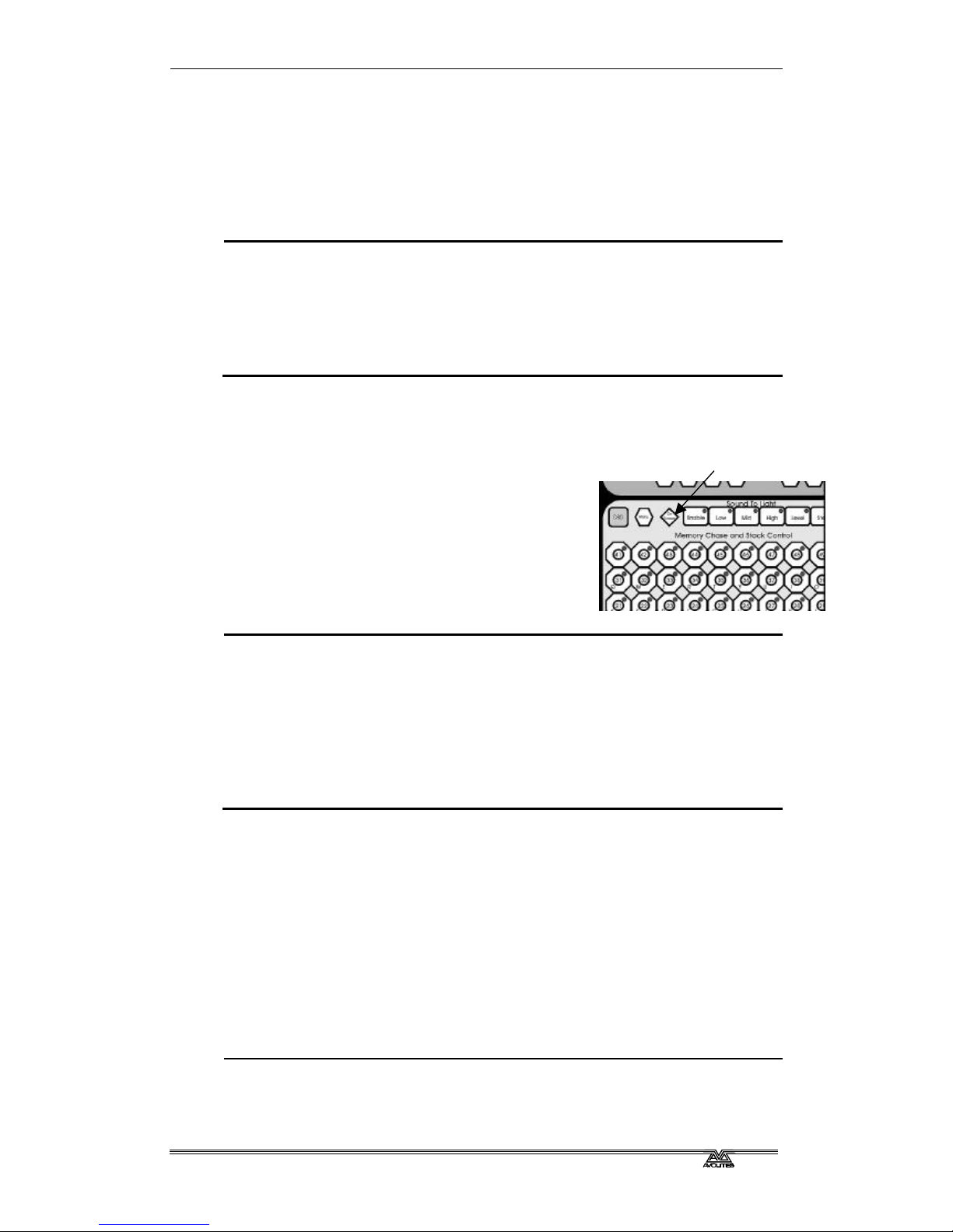
6.7 Sound activation of chases
The Azure can use bass, mid or treble frequencies from its audio input to
Page 36

Page 30 - Fehler! Formatvorlage nicht definiert.. Fehler! Formatvorlage nicht definiert.
AZUREM2.DOC 18.03.1999 12:40
trigger chases. The current version of the software triggers playback 1
from low frequencies (bass), playback 2 from
mid and playback 3 from high frequencies
(treble).
Future versions of the software will allow any
chase to be triggered from any of the sound
frequencies and will use the other sound to light
buttons, which currently have no function.
6.7.1 Sound activating chases
? ? Press the Sound to light Enable button
? ? The Low, Mid and High buttons flash in time to the sound signal
? ? Chases stored in playbacks 1,2,3 will step in time to the sound signal
? ? The Speed wheel controls the maximum speed of the chase
? ? Press the Enable button again to turn off sound activation.
Sound enable
Page 37

Fehler! Formatvorlage nicht definiert.. Fehler! Formatvorlage nicht definiert. - Page 31
AZUREM2.DOC 18.03.1999 12:40
CHAPTER SEVEN
7. Environments and the scheduler
In this chapter: using environments and what the scheduler does
?? What an environment is
?? Recording an environment
?? Playing back an environment
?? The scheduler
7.1 What is an environment?
An environment is a snapshot of the playbacks on the console, which
includes all memories and chases which are turned on. They can have a
fade in and fade out time. Environments can be useful in a show if you
need to turn on several memories at the same time. They are also used
when you are using the scheduler on the Azure to run a timed show
automatically.
The Azure can store 2 pages of 10 environments (that’s 20 in total, for the
mathematically challenged).
7.2 Recording an environment
Recording an environment is simply done by setting the
playbacks you want at the levels you want them, then using the
Record Environment option.
7.2.1 Recording an environment
? ? Set up the playbacks you want in the environment at the
levels you want them
? ? Press the Menu button in the environment section
? ? Press Softkey B, “Record an Environment”
? ? Press the Environment button you want to use
? ? The current playbacks will be recorded into the environment
? ? Fade in and out times are set to 3 seconds
Note: If the environment was already used, it will be overwritten
by the new environment.
You can assign a text label to an environment using the Set
Legend button, which works the same as for memories. Press the On
Screen button below the environment buttons to display the contents of
the environments.
You can change the fade in and fade out time of the environment using the
Environment Parameters option on the menu.
7.3 Playing back an environment
You play back an environment by pressing the button.
Environment
menu button
Page 38

Page 32 - Fehler! Formatvorlage nicht definiert.. Fehler! Formatvorlage nicht definiert.
AZUREM2.DOC 18.03.1999 12:40
7.3.1 Playing back an environment
? ? Press the environment button
? ? The playbacks in the environment will fade up in the Fade In time
? ? To turn it off, press the button again
? ? The playbacks in the environment will fade down in the Fade Out time
You can take over control of a playback in the environment by pressing the
button (for a 11-50 playback), or by putting the fader to full then to zero
(for a 1-10 playback).
7.4 Other environment controls
Future versions of the software will allow environment chases, and realtime recording of shows. Currently the environment chase control buttons
and the Connect, Load Step and Learn buttons in the environment area
have no function.
7.5 The scheduler
The scheduler is designed for unattended operation of a light show. It will
automatically turn on an environment at the time you specify, and then
turn it off again after the duration you have set. This can be repeated in
various modes.
How to use the scheduler is described in detail in the reference manual.
Page 39

Fehler! Formatvorlage nicht definiert.. Fehler! Formatvorlage nicht definiert. - Page 33
AZUREM2.DOC 18.03.1999 12:40
CHAPTER EIGHT
8. The graphics tablet
In this chapter: using the graphics tablet with the Azure
?? Using the tablet
?? Functions available on the tablet
The graphics tablet is an optional extra to the Azure, which allows you to
use a pen to select fixtures, groups, colours, and position the fixtures by
simply drawing with the pen. You will be amazed how much easier your
programming and show operating becomes when you use the tablet.
8.1 Using the tablet
To use the tablet, you simply press the pen onto it. The button on the side
of the pen doesn’t do anything. A quick press is like pushing a button on
the Azure. You can also draw on the tablet by keeping the pen pressed
down while moving it. This is used to move fixtures or change attributes.
The Azure will behave as if you are pressing buttons on it in the normal
way, so the LEDs and the VGA display will change as you use the tablet.
Many of the functions of the Azure are quicker and easier using the tablet.
Sometimes you might find it easier to do part of the function on the tablet
and part on the console. The end result is the same.
The tablet has a paper overlay on it. You can write your fixture names,
group names, attributes, palette entries and even draw your stage layout
on the overlay so that you know what’s what. Spare overlays are available
from Avolites.
8.2 Functions available on the tablet
To select a fixture or a group, just press the pen onto the fixture button or
the group button. The first 60 fixtures which are patched will appear in
order on the tablet (press the Menu button below the “Flip” button, then
Softkey A “Fixture Layout on Tablet” to display a list). Only the first 30
Colour control
Position control
Attributes
Groups
Palettes
Fixtures
Page 40

Page 34 - Fehler! Formatvorlage nicht definiert.. Fehler! Formatvorlage nicht definiert.
AZUREM2.DOC 18.03.1999 12:40
groups are available on the tablet.
You can control the position of the fixture by drawing on the Stage area of
the tablet.
You can “train” the Azure so that it knows how all the lights are set up.
Then when you point at the stage area of the tablet, all the lights will point
at the same place on the stage. This is called “Tracking mode”. The
Reference manual tells you how to do this and how to use tracking mode.
If you press on the Nudge button, when you draw on the tablet the fixture
will move relative to its current position. This can be useful if you want to
slightly reposition a fixture. Press on the Absolute button to turn off this
mode.
You can control the intensity of the selected fixtures by drawing on the
Dimmer area.
If the fixture can do colour mixing, you can set the colour by drawing in
the colour mix area of the tablet.
You can recall the first 60 palette entries by pressing the pen on the
Focuses buttons.
You can change individual attributes of selected fixtures by pressing the
pen on to the attribute button, then (without lifting the pen) drawing up
and down on the tablet.
On the right hand side of the tablet, some of the programmer functions are
available, such as Clear and Locate Fixtures.
Page 41

Fehler! Formatvorlage nicht definiert.. Fehler! Formatvorlage nicht definiert. - Page 35
AZUREM2.DOC 18.03.1999 12:40
CHAPTER NINE
9. Advanced features
Hopefully, by working through this tutorial manual, you now know how to
set up the Azure, control fixtures with it, save memories, chases and
environments and use them in a show.
We have tried to stick to the basics, but the Azure can do many more
things than we have told you so far. The reference manual expands on all
the information in the previous chapters. There’s also some subjects we
have not touched on yet, and these are described in the reference manual.
Just so you know, they are:
?? User Preferences - Some console options you can change
?? Setting the real time clock
?? Disk functions - there are a few more things you can do with the disk
drive
?? Tracking - You can train the Azure so it knows how the fixtures are
positioned relative to the stage. You can then point all the fixtures at
one part of the stage by clicking on the graphics tablet (or by using the
wheels, if you don’t have a graphics tablet). Training is described in
Chapter 3 of the reference manual and use of the graphics tablet in
tracking mode is described in Chapter 8.
?? MIDI - The Azure has a very comprehensive MIDI control system
?? Use of the optional Stage Remote control
?? Script files - You can tell the Azure how to run a show from a list of
instructions which you can enter or record in real time. This is
described in chapter 7 of the reference manual.
?? Changing the operating system - From time to time Avolites release a
new version of operating software, which you can load into the Azure
?? Personality files - if the Azure doesn’t have a personality file for your
fixture you can write your own. These are described in chapter 11 of
the reference manual.
?? Resetting the PIN codes and other devious hardware tricks
Page 42

Page 36 - Fehler! Formatvorlage nicht definiert.. Fehler! Formatvorlage nicht definiert.
AZUREM2.DOC 18.03.1999 12:40
Page 43

Fehler! Formatvorlage nicht definiert.. Fehler! Formatvorlage nicht definiert. - Page 37
AZUREM2.DOC 18.03.1999 12:40
CHAPTER TEN
10. Introduction to intelligent lighting
This section is for those who have not used intelligent lighting much
before, who are put off by dip switches, lights that move unexpectedly and
strange digital control systems that fly down microphone cables.
10.1 Ordinary lighting
Standard lighting consists of a variety of light bulbs connected to dimmers.
The lights may be anything from par cans to theatrical lanterns, and the
dimmer controls the intensity of the light. A typical controller for standard
lighting has a set of sliders, and each slider controls the intensity of one
dimmer using a low-voltage control signal of 0 to 10 volts. The standard
way to link the sliders to the dimmers is by using a multicore cable with
one core for each dimmer channel.
10.2 So what is intelligent lighting?
Intelligent lighting usually contains more functions than just intensity; a
typical intelligent light, often called a “fixture”, can also change colour,
project different patterns (called “gobos”) and direct the light beam in any
direction using a movable mirror or by motorised control of the light unit
itself. The fixtures are called “intelligent” because they contain a small
computer which controls the movement of the internal motors in response
to the control signals. Most fixtures can also listen to music and produce
their own light show, sometimes synchronising themselves with other
intelligent fixtures. However they are actually not all that intelligent and
usually need a user to make them do something interesting.
10.3 How do you control it?
Each function of an intelligent fixture requires its own control signal, so the
user can select the colour, position, gobo etc. You can use 0 to 10 volt
control signals on some fixtures, but the cable carrying the control signals
again has to be a multicore with one core for each function, so each fixture
might need 8 or more cores in the control cable. Some of the more
complicated fixtures use 20 channels.
When several fixtures are used, the number of cores needed in the control
cable soon becomes large. The cable also has to split at each fixture. It all
gets a bit complicated.
10.4 The DMX control system
Fortunately, there is an easy to use system for controlling intelligent
lighting and dimmers. It is called DMX-512, which stands for Digital
MultipleX, and it sends up to 512 control signals down a 2-core screened
cable. The cable can be simply daisy-chained from each fixture to the next.
Microphone-style XLR connectors are usually used, sometimes 3-pin and
sometimes 5-pin.
The DMX system sends out the level for channel 1, followed by the level
for channel 2, then 3, then 4 and so on, all the way up to a maximum of
512 (though not all DMX systems send out all the channels). It then goes
back to channel 1 again. All the units connected to the DMX receive all the
channels, and you tell them which channels to respond to by setting the
“base channel” or “DMX address” on each unit. The computer inside the
Page 44

Page 38 - Fehler! Formatvorlage nicht definiert.. Fehler! Formatvorlage nicht definiert.
AZUREM2.DOC 18.03.1999 12:40
fixture waits for the correct channels to come up, then reads in the levels
for those channels.
Dimmers can also understand DMX; some dimmers can read it directly,
others use a demultiplexer or “demux” to convert the DMX into the normal
0 to 10 volt analogue signals they are used to.
10.5 Moving light control desks
Sliders are ideal for controlling dimmers. More complicated dimmer control
desks have memories to record the level of all the dimmers, so you can
recall a setting without having to set all the sliders again during a show.
However, once you start controlling lights that move and change colour,
sliders become less ideal, because it is the movement rather than the end
level which is important. Dedicated moving light desks such as the Azure
include many helpful functions which makes the programming of
intelligent lighting much easier, such as palettes of pre-programmed
colours and positions, and a shape generator to create movements.
10.6 A few cautions about using DMX
DMX is a robust system which normally works very well, but sometimes it
can be problematic. Here are a few tips for making DMX work well.
?? DMX cabling should be twisted-pair data cable. Microphone cable is not
recommended because it doesn’t transmit the signal as well. You will
probably get away with it, but equally you might have problems.
?? Always connect a terminator plug on the last fixture. This has a 120
ohm resistor across the DMX line and prevents data interference on the
line. It might work without but…
?? Don’t split the DMX cable. Loop it from one unit to the next. If you
have to split it, use a proper active splitter unit.
?? Don’t try to run more than 16 fixtures from one DMX line. Either use
several DMX lines (the Azure has four) or use a DMX repeater unit.
Again, you will probably get away with using more if you have to, but
the DMX signal will be weaker than it should be.
?? Don’t run your DMX lines near high voltage cables or neon. They may
pick up interference which will stop the system working, or worse, blow
up the receiver electronics in the fixtures (this really does happen).
Page 45

Azure 2000
Reference Manual
Page 46

Page 47

REFERENCE MANUAL CONTENTS
1. SETTING UP THE CONSOLE 105
2. PATCHING 109
3. CONTROLLING DIMMERS AND FIXTURES 113
4. USING SHAPES 121
5. RECORDING AND PLAYING BACK MEMORIES 125
6. RECORDING AND PLAYING BACK CHASES 133
7. ENVIRONMENTS, THE SCHEDULER, SCRIPT FILES 139
8. USING THE GRAPHICS TABLET 145
9. ADVANCED FEATURES 149
10. THE PERSONALITY FILE SYSTEM 155
11. CONTACTS FOR FIXTURE MANUFACTURERS 166
12. GLOSSARY OF TERMS 168
13. BUTTON INDEX 174
14. INDEX 176
Page 48

Page 49

Fehler! Formatvorlage nicht definiert.. Fehler! Formatvorlage nicht definiert. - Page 105
AZUREM2.DOC 18.03.1999 12:40
CHAPTER ONE
1. Setting up the console
This chapter contains: Connecting mains power; connecting DMX lines;
connecting MIDI devices; connecting audio; the disk drive; other back
panel connections and controls; desk modes.
1.1 Connecting mains power
The Azure uses a universal switch mode power supply which allows it to
run off any mains voltage from 90 to 250V at 50Hz or 60Hz. You don’t
have to set a voltage selector. Just plug in and go.
1.2 Connecting DMX lines
The Azure can output DMX down 4 separate lines. When you patch a
dimmer or fixture you can tell the Azure which DMX line it is on. The lines
are identified by the letters A,B,C,D. Normally A comes out of output 1, B
comes from 2, C from 3, and D from 4, but just to add to the fun you can
swap this round if you want (see Patching, section 2).
The 4 DMX outputs come out of the two 5 pin XLR sockets on the back of
the console. They are wired like this:
DMX line Pin numbers Socket
1 (normally A) 2=Data -
3=Data +
1
2 (normally B) 2=Data -
3=Data +
2
3 (normally C) 4=Data -
5=Data +
1
4 (normally D) 4=Data -
5=Data +
2
If you use a standard DMX cable, you will get Line 1 (normally A) on
output 1 and line 2 (normally B) on output 2.
Lines 3 and 4 use the spare pins 4 & 5 on the output sockets. If you want
to use both lines on a socket, you need a splitter, which you can either buy
from Avolites or make up yourself.
The 5 pin XLR plug labelled “DMX input” on the back of the console is not
currently in use.
1.3 Connecting MIDI devices
The Azure has the usual MIDI IN, OUT and THRU connections. It can read
MIDI information and use it to trigger a show, and it can output MIDI
information in response to user actions on the controls. This means you
can record a show straight into a MIDI sequencer by operating the show
yourself using the buttons and sliders.
1.4 Connecting audio
The Azure has a left and right audio input socket, and a gain control to set
the sensitivity of the sockets. The Azure uses the audio inputs for sound to
light functions.
Page 50

Page 106 - Fehler! Formatvorlage nicht definiert.. Fehler! Formatvorlage nicht definiert.
AZUREM2.DOC 18.03.1999 12:40
There is an internal link on the PCB to set the overall sensitivity of the
audio inputs. It is located under the VGA card near the audio connectors
labelled “Preset Gain Links” and can be set to 0dB, 20dB or 40dB by
bridging one of the pairs of jumpers.
1.5 The disk drive
The Azure has a 1.44M floppy disk drive which is used to load and save
shows, personality files and system software. The standard PC disk format
is used, so you can transfer data to and from your PC. You can use the
smaller 720K disks, but large shows may not fit!
You should get into the habit of backing up your show to disk regularly to
guard against that moment when something goes wrong. It doesn’t take
long.
1> Press Disk in the top left hand corner of the Azure
2> Insert a blank formatted 1.44M disk into the disk drive.
3> Press softkey B, “Save show to disk”. Enter a name. The Azure will
save the show.
4> To reload the show, use softkey A, “Load show from disk”.
The disk drive functions are all obtained by pressing the Disk button on the
Azure. The disk drive functions are described in section 9 on page 150.
1.6 Other back panel connections and controls
Also on the back panel are the following:
The QWERTY socket is for connecting a standard PC keyboard. This can be
used for entering legends rather than using the letters on the playback
keys.
The Serial Port is for connecting the graphics tablet or the Stage Remote.
The VDU socket is for connecting the VGA display. Any standard VGA
display will be OK. If you don’t need to see what the Azure is doing, e.g.
for unattended operation, it will operate fine without the VGA display.
The Desk Lamp socket is for the gooseneck light.
The Reset button just above the power socket allows you to restart the
Azure if something funny happens to it. The Azure will come back to the
same place it was in when you pressed Reset, but all
playbacks will be turned off. The memory is not
affected.
1.7 Azure modes
When the Azure first powers up, it is in Operate
mode. In this mode all you can do is run playbacks.
If you need to prevent people from messing around
with the console, or you want to run a show without
risk of changing anything, this is the mode to put it
in. If you press Operate twice, the Azure enters a
special “quick key response” mode.
When programming, you need to be in Program mode, which you access
by pressing the Program button. This manual assumes you are in program
mode. You can set a PIN code to prevent unauthorised access to Program
mode.
Desk mode buttons
Page 51

Fehler! Formatvorlage nicht definiert.. Fehler! Formatvorlage nicht definiert. - Page 107
AZUREM2.DOC 18.03.1999 12:40
Supervisor mode allows you to clear the console using softkey F, “Wipeall”.
Another PIN code can be set for Supervisor mode.
AVO mode allows you to do anything to the console, including Wipeall,
changing the PIN codes, various diagnostics and loading a new operating
system. AVO mode has a default PIN code of 1234 but you can change
this. There are more details about AVO mode in Section 9 on page 153.
Page 52

Page 108 - Fehler! Formatvorlage nicht definiert.. Fehler! Formatvorlage nicht definiert.
AZUREM2.DOC 18.03.1999 12:40
Page 53

Fehler! Formatvorlage nicht definiert.. Fehler! Formatvorlage nicht definiert. - Page 109
AZUREM2.DOC 18.03.1999 12:40
CHAPTER TWO
2. Patching
This chapter contains: Fixture select buttons; patching dimmers; patching
moving light fixtures; checking the patching; changing the DMX address;
moving a fixture to a different select button; patching options.
Patching is the process where you tell the Azure
?? What type of lighting units you have connected to it
?? What DMX addresses they are operating at
?? Which DMX output line each unit is connected to
(there are 4)
?? Which fixture select buttons you want to use to
access them
You can either patch the DMX channels on your console
to match your lighting rig, or set up the console first and
then set the lighting rig to match.
The Azure must be in Program mode before you can patch.
2.1 Fixture select buttons
The Azure can control up to 200 intelligent fixtures, and 200 dimmer
channels. To do this it has 10 pages of 20 fixtures and/or dimmers.
If you have a mixture of fixtures and dimmers, you have two options:
1. Patch the dimmers to one set of pages and the fixtures to another
(separated patch). This means you don’t have to press the Dimmer or
Fixture button every time you select something, but the total number
of fixtures and dimmer channels can’t exceed 200.
2. Patch dimmers and fixtures on the same pages or even the same
buttons (overlay patch). This means you can have 200 fixtures and
200 dimmers, but you need to press the Dimmer or Fixture button
before selecting anything, so the Azure knows whether to activate the
dimmer or the fixture allocated to the button.
The Azure also allows you to allocate fixtures and dimmers to Groups,
which can get round the need to press the Dimmer/Fixture button. Groups
are described in the next chapter.
2.2 Patching dimmers
Each dimmer channel is allocated to one of the fixture select buttons. If
you want to link dimmers together, you can allocate several to the same
button.
1> Press Patch, Dimmer, Dimmer/Fixture Page
2> On the VGA display, the Azure shows the DMX address it is going
to patch at. You can change this using the numeric keypad. You
can also use softkey C “Select a DMX line” to patch onto one of the
other 3 DMX output lines.
3> To patch a single dimmer, press a Fixture Select button. To patch
a range of dimmers, hold down the Fixture Select button for the
Fixture select buttons
Page 54

Page 110 - Fehler! Formatvorlage nicht definiert.. Fehler! Formatvorlage nicht definiert.
AZUREM2.DOC 18.03.1999 12:40
first dimmer in the range, then press the last button in the range.
The range of dimmers will be patched to sequential DMX
addresses.
4> To patch another dimmer to the same button, just press the
button again
5> Repeat from step 2 for other dimmers.
?? The VGA display will show the channels which have been patched. You
can patch multiple dimmers onto the same button by simply pressing
the button again when you get to the DMX address for the appropriate
dimmer.
?? Press Softkey A to set options for the dimmer channels. You can set the
Full on level to less than 100% using option A, and select a different
dimmer response curve using option B. To use the “User curve” setting
you need to load in a user curve, see page 150.
2.3 Patching moving light fixtures
Moving light fixtures are more complicated to patch than dimmers because
they have more attributes to control, such as pan, tilt, colour etc., where a
dimmer channel just has intensity. When you patch a fixture, you will see
on the display that it occupies a block of DMX channels rather than just
one.
The Azure uses a “personality file” system to control fixtures. There is a
personality file in the Azure for each fixture, which tells it what attributes
are available and how to control them. In the unlikely event that there
isn’t a personality for the fixture you are using, you can either create one
yourself (see chapter 10) or contact Avolites, who will be able to create
one for you.
Note: You will need a Personality Disk in the disk drive, or to have loaded
the personality cache from a disk into the Azure, before you can
patch fixtures. The personality cache only needs loading once, and
how to do it is described on page 154.
If you are using the internal personality cache, ensure there is no disk in
the disk drive.
1> Press Patch, Fixture.
2> The display will show “Please wait … reading files” on the bottom
line. A list of known manufacturers will appear after a pause.
3> Use the cursor arrows to select the manufacturer of your fixture.
4> Press Enter. The display will show all available fixtures for that
manufacturer.
5> Use the cursor arrows to select the correct fixture. Press Enter.
6> The Azure will ask “Automatically create palettes?”. Press Softkey
A for Yes. This loads a standard set of positions, colours and gobos
into the Palette pages which can be useful when programming. If
you say No now, you can’t load them later.
7> On the VGA display, the Azure shows the DMX address it is going
to patch at. You can change this using the numeric keypad. You
can also use softkey C “Select a DMX line” to patch onto one of the
other 3 DMX output lines.
8> Select Dimmer/Fixture page to be used.
9> Press a Fixture Select button to patch the fixture. The display will
show the block of channels occupied by the fixture.
Page 55

Fehler! Formatvorlage nicht definiert.. Fehler! Formatvorlage nicht definiert. - Page 111
AZUREM2.DOC 18.03.1999 12:40
10> Repeat from Step 7 to patch more of this type of fixture.
11> Press softkey A (“Select another fixture”) and repeat from Step 3
to patch a different type of fixture.
You can patch a range of fixtures by holding down the first and last
buttons of the range, the same as for dimmers.
2.4 Checking the patching
Having set the Azure, you need to ensure that your
lighting rig is set up to match the Azure by going
round your rig to set the DMX addresses.
You can display the DMX settings on the Azure like
this.
1> Press the On Screen button below the cursor
arrows
2> Press Fixture or Dimmer
3> Select the page of fixtures you want to look at
4> Press a fixture select button
5> The screen shows the fixture type and DMX line and address (e.g.
A24 is address 24 on DMX line A). The dip switch settings may
also be shown if the fixture personality includes this information.
6> Repeat from Step 4 to view other fixtures.
?? Press the On Screen button, then Softkey A “Patch by DMX” to display
a list of all DMX channels, what they are allocated to and the current
output. The cursor arrows scroll through the list.
?? The On Screen button then Softkey B, “Patch by Fixture”, displays a list
of all the fixtures and shows the DMX addresses allocated to them.
2.5 Changing the DMX address
You can re-patch a fixture to a different DMX address or a different DMX
output line. All programming is kept.
1> Press Patch.
2> Press Softkey E “Repatch Fixtures”.
3> Use the numeric keypad to enter the new DMX address of the
fixture. If you want to change the DMX output line, press Softkey
E “Select a DMX line” and choose a new output line by pressing A
B C or D.
4> Select the page for the fixture you want to change.
5> Press the fixture select button to patch that fixture at the new
address.
6> Press Enter to confirm the change.
7> Repeat from step 3 if you want to change other fixtures.
2.6 Moving a fixture to a different select button
You can move a dimmer or fixture from one select button to another
simply by entering the DMX channel to match the fixture, then patching it
again onto another button. However, all programming is lost for that
dimmer channel or fixture.
System on screen
Page 56

Page 112 - Fehler! Formatvorlage nicht definiert.. Fehler! Formatvorlage nicht definiert.
AZUREM2.DOC 18.03.1999 12:40
2.7 Patching options
The Azure allows several options to be set for each fixture or dimmer when
it is being patched. The Patch Options menu is accessed by pressing
Softkey F “Patch Utilities” while you are in patch mode. Set the options
before you start programming, because memories will play back differently
when the options are on.
The options are:
A: Invert - Allows you to invert an attribute of a fixture, so when you set
zero the output will be full. You cannot invert some attributes.
1> Select the fixtures you want to invert
2> Select the attribute you want to invert (some can’t be changed)
3> Press E or F to invert the attributes shown (the VGA display shows
the current setting as NORMAL or INVERTED)
4> Repeat from 2 if you want to invert more attributes, or 1 if you
want to change other fixtures.
B: Set/Reset Instant mode - When the Azure fades LTP (movement)
channels between two memories, the LTP values normally change
smoothly. You can set Instant mode to make the channel snap instantly to
the new value.
1> Select the fixtures you want to change
2> Select the attribute you want to change (some can’t be changed)
3> Press E or F to change the attributes shown (the VGA display
shows INSTANT or FADE)
4> Repeat from 2 if you want to change more attributes, or 1 if you
want to change other fixtures.
C: Swap pan and tilt - If you have some fixtures mounted sideways, it
can be useful to swap the pan and tilt channels over.
1> Press the Pan/Tilt attribute button so you can see the setting
2> Press the fixture select buttons of the fixtures you want to swap
3> Repeat from 2 to change other fixtures.
D: Set DMX lines - The Azure has 4 DMX output lines, this option lets you
set which connectors they come out of. You can output the same DMX line
from more than one connector if you want to.
You can also use this option to set the highest DMX channel to transmit.
This will speed up the DMX refresh rate if you are not using all 512
channels. (This option can also be set from the User Preference menu).
E: Find fixture - This option lets you find “lost” fixtures (if you have set
the DMX address and forgotten what it was).
1> Using the cursor arrows, select the type of fixture & press enter
2> Spin wheel A until the fixture responds (open white beam, central
position)
3> You can change the DMX output line using the A B C D softkeys or
directly enter a channel by pressing softkey G
4> Read the DMX address from the VGA display.
Page 57

Fehler! Formatvorlage nicht definiert.. Fehler! Formatvorlage nicht definiert. - Page 113
AZUREM2.DOC 18.03.1999 12:40
CHAPTER THREE
3. Controlling dimmers and fixtures
This chapter contains: Selecting fixtures and dimmers for control;
changing attributes of the selected fixtures;using groups; the align and flip
buttons; using palettes; entering levels as numbers; the ML menu and
tracking.
When you are programming a show, and sometimes when you are running
a show, you need to manually control the fixtures and dimmers to set the
intensity, position, colour, etc. To do this you first select the fixtures you
want to change, then you set the attributes of those fixtures.
3.1 Selecting fixtures and dimmers for control
To select the fixtures or dimmer channels that you want
to control, you use the fixture pages and the fixture
select buttons. You can select fixtures or dimmers
individually, or several at once.
Selection of fixtures is identical to selection of dimmer
channels, so for “fixtures” read “dimmers” as well.
1> Press the page for the fixtures
2> If there are both dimmers and fixtures on the
page, press Fixture or Dimmer to select which
type you want.
3> Press the fixture select buttons for the fixtures you want. Selected
fixtures are shown in dark blue on the VGA display
4> To select a range of fixtures, hold down the first fixture button
then press the last fixture button.
Here are some other things to know:
?? The fixture select buttons light up to show which fixtures are patched.
?? Press “Locate Fixture” to position the selected fixtures in open white at
a central position (dimmer channels go to 50%).
?? If a range of fixtures is selected, or a group, the Last Fixture and Next
Fixture buttons deselect the range then step through the fixtures in
the range selecting them one at a time. The Highlight button turns on
the dimmer of the fixture that is currently selected. The Select All
button reselects the fixtures in the range.
?? You can deselect a fixture by pressing the fixture select button again.
You can deselect all fixtures by pressing the Deselect Fixture button,
and if you are not in the last/next fixture mode described above, you
can select all fixtures on the current page by pressing the Select All
button.
?? Once you have changed any attribute, pressing a fixture select button
will deselect all fixtures and start the selection process again.
?? The Kill and Quick Look buttons are not implemented in the current
software.
Fixture pages
Page 58

Page 114 - Fehler! Formatvorlage nicht definiert.. Fehler! Formatvorlage nicht definiert.
AZUREM2.DOC 18.03.1999 12:40
3.2 Changing attributes of the selected fixtures
“Attributes” are the functions of the fixture, like pan, tilt, colour, dimmer,
and are set using the wheels at the bottom of the Azure. The attributes
available depend on the fixture type. Dimmer channels only have a
dimmer attribute. The Azure can control up to 40 attributes per fixture.
Each attribute button can control two attributes, one on the left wheel and
one on the right wheel.
1> Press the button for the attribute to be changed
2> Turn the wheels to set the attribute. The bottom
right hand corner of the VGA display shows
which attributes are being controlled and the
current values.
3> The top part of the VGA display shows the
fixtures which are being changed
4> Repeat from 1 to change other attributes of the
selected fixtures.
Some other things to know about attributes:
?? The Attribute buttons let you select the first 20 attributes. Another 20
attributes are available by pressing the Shift button, to cater for the
weird and wonderful DMX fixtures of the future. The light on the Shift
button stays on when you are using the top 20 attributes.
?? If the VGA display does not show the attribute when you press the
button, that attribute is not available on the selected fixtures.
?? Fixtures which don’t have a Dimmer function usually use the Gobo
function to black out the fixture.
3.3 Using groups
You can create groups of fixtures or dimmer channels, to make selecting
them faster. You can, for example, make a group for each type of fixture,
or group by left / right stage, etc. You can then select all the fixtures in
the group just by pressing one button.
1> Select the fixtures/dimmers you want in the group (the order in
which you select them will also be stored in the group)
2> Press Record, then Group
3> Select the page on which you want to store the group (the page
buttons are the same ones used for fixture pages)
4> Press the select button where you want to store the group
5> Repeat from 1 to store other groups
Other useful things to know about groups:
?? Once you have created a group, you can then instantly select all the
fixtures/dimmers in the group simply by pressing Group, then a select
button. All other fixtures and dimmers are deselected.
?? You can enter names for groups to help you remember what’s in them.
Press Input Legend, then the group button to name. Enter a name
using the letters on the playback buttons, or an external keyboard if
you have plugged one in. Press Enter to save it.
?? The VGA display shows the contents of the current page of groups.
Attribute control
Page 59

Fehler! Formatvorlage nicht definiert.. Fehler! Formatvorlage nicht definiert. - Page 115
AZUREM2.DOC 18.03.1999 12:40
?? You can use the Next Fixture / Last Fixture buttons to step through the
fixtures in the group. The order in which the Azure steps through will
be the order you originally selected the fixtures when you created the
group.
?? You can delete a group by pressing Group, then Cut, then the select
button for the group.
3.4 The Align and Flip buttons
The Align button allows you to set the same level on a particular attribute
for a range of fixtures. This can be useful if you want to set a row of scans
to have the same tilt position, or if you want to set a
colour from one fixture onto other fixtures.
1> Press an attribute button to select the
attribute you want to align.
2> Select the fixture to use as the reference
3> Select the other fixtures you want to align
to the first one
4> Press Align.
5> The attributes will be aligned on all the
selected fixtures.
?? If you use a group to select the fixtures, the one
you selected first when you recorded the group will be the reference
fixture.
?? If Tracking mode is on (see page 118), aligning the Pan/Tilt attribute
will cause all the fixtures to point at the same place on the stage rather
than copying the actual Pan/Tilt values.
The Flip button is only used with moving head fixtures. This type of fixture
has two possible pan and tilt positions for each point on stage, and the Flip
button alternates between them. This allows you more freedom to make
movements without hitting the pan stop.
3.5 Using palettes
When programming a show you will find that you frequently use certain
positions, colours, etc. Like an artist’s palette, the Azure lets you store
these settings so you can recall them at the touch of a button. There are
10 pages of 20 palette entries. You can name the palette values so that
you know what you’re getting.
Also, when you patch a fixture, the Azure loads 10
preset positions, 10 colours and 10 gobos into the
palette for that fixture. The colours are always the
same for all fixtures, so you know that if you select
“Red” you are going to get red on everything, even
though the Azure is sending out different values to
the different types of fixture.
Palette values stored as a reference
The most important thing about palettes is that when
you use a palette value in a memory, the Azure
stores a reference to the palette, rather than the
actual value. This means that if you program your
Palette pages
Flip and Align buttons
Page 60

Page 116 - Fehler! Formatvorlage nicht definiert.. Fehler! Formatvorlage nicht definiert.
AZUREM2.DOC 18.03.1999 12:40
memories using palettes, you can easily change all the positions just by
reprogramming a few palette entries rather than having to reprogram all
the memories. This is handy if you are touring a show and have to cope
with different stages or truss heights every show.
Shared and individual palettes
Palette entries can be shared or individual.
?? Shared: If you only have one fixture selected when recording the
palette entry, then you can use that palette entry for all fixtures of the
same type. So you could save a value for “Red” on the first of your
Wackylites™, and then use that value for any of your Wackylites. This
is a shared palette, useful for values which are the same for all the
fixtures of one type, such as colour, gobo, prism etc. The preprogrammed palettes are all shared.
?? Individual: If you select more than one fixture when recording the
palette entry, then the entry is unique for each fixture. So when you
save an entry with pan/tilt positions for your 4 central Wackylites,
those positions will only ever apply to those fixtures. You can later add
values for other fixtures; fixtures which have no values saved will not
change when the palette is recalled. This is an individual palette, useful
for values which vary for each fixture, like pan, tilt and focus.
Which attributes are stored in palettes
A palette entry can store any or all attributes of a fixture, so you could
store colour and gobo in the same palette entry. Only the attributes you
have changed will be recorded. You can also “mask out” some of the
attributes, when saving the palette entry.
To save all the changed attributes, select the Dimmer attribute when
saving the palette. All the attribute lights will come on to show you that
they are all going to be used. To save one individual attribute, press one of
the other attribute buttons (the Colour attribute also selects the Yellow /
Magenta / Cyan colour mix attributes). You can save other attributes later
if you need to.
This is how you save a palette value:
1> Press Clear to clear the programmer.
2> Select the fixtures for which you want to store palette values.
Select one fixture only to record a shared palette entry.
3> Set the attributes you want in the palette entry. You can store any
or all attributes of a fixture in each palette entry. Only attributes
you have changed will be recorded.
4> Press the attribute button for the attributes you want to store (the
dimmer button will store all attributes). The buttons light up to
show you which attributes are going to be recorded.
5> Press Record, press Palette, press the palette page you want to
use, then press one of the fixture select buttons to store the
palette entry under that button.
6> Name the palette entry by pressing Input Legend, then the palette
select button, then enter the name using the letters on the
playback buttons or an external Qwerty keyboard.
To recall a palette value, this is what you do:
Page 61

Fehler! Formatvorlage nicht definiert.. Fehler! Formatvorlage nicht definiert. - Page 117
AZUREM2.DOC 18.03.1999 12:40
1> Select the fixtures to be changed. Shared palettes can be set to
any fixture of the same type. Individual palettes will set individual
values to each fixture.
2> You can apply the palette values instantly, or fade to them by
pressing one of the Fast / Medium / Slow buttons at the side of
the sliders (this can be useful in the middle of a show)
2> Press Palette, press the palette page number you want, then press
the select button for the palette entry you want (the VGA display
shows the contents of the page). The fixtures will be set to the
palette values.
Other useful things to know about palettes:
?? You can edit a palette entry by recalling it, making the changes you
want, then saving the new information back on top of the existing
palette entry. Anything you haven’t changed will not be affected,
values you have changed or added will be amended.
?? You can delete a palette entry by pressing Cut, Palette, then the select
button for the palette entry to be removed
?? You can set the fade times for the Fast / Medium / Slow buttons by
pressing Set Time, then the button you want to set, then entering the
fade time in seconds on the numeric keypad.
?? You can change the way the attributes are grouped when saving
palette entries by selecting the attribute button to change, then
pressing the Menu button below the Palette button, then option A
“Specify attributes for bank”. The buttons will light to show which
attributes are saved when that button is selected. You can press the
buttons to include or exclude attributes. Press Exit twice to finish.
3.6 Entering levels as numbers
You can set levels using the numeric keypad as you
would on a theatrical lighting desk. This can be faster
when plotting dimmer levels for a scene than using
the select buttons and the wheels.
1> Type the dimmer number (not the DMX
channel) on the keypad.
2> Press “@”.
3> Press 0 - 9 for the intensity, or “@” again (or
Softkey D) for 100%
4> Press the decimal point key and another digit for more accurate
control
5> If you need to display the dimmer numbers, press the System On
Screen button (below the cursor arrows), then softkey B “Patch by
fixture”
Other things you can do by numeric entry:
?? The softkey options are D:set to 100%, E:up by 5%, F:down by 5%.
?? You can set multiple dimmers to the same level using the “thru”
button. Enter first dimmer, “thru”, last dimmer, “@”, level.
Numeric keypad and @
Page 62

Page 118 - Fehler! Formatvorlage nicht definiert.. Fehler! Formatvorlage nicht definiert.
AZUREM2.DOC 18.03.1999 12:40
?? The Azure normally controls dimmers this way, but Softkey C “Set
Fixture Type” on the main menu lets you change this to control one of
the other fixture types you have patched.
?? If you change the type to a fixture, you select the fixture by entering
the fixture number, then @. You can use “thru” to select multiple
fixtures.
?? To set a fixture attribute, select the attribute using the Attribute
buttons. Enter the value, then press Softkey E (left wheel attribute) or
F (right wheel attribute) to set the value. The VGA display shows which
attributes are going to be set.
?? You can recall groups of fixtures or dimmers (type group number, then
press softkey A).
?? You can recall palette entries (type palette entry number, then press
softkey B)
?? You can change the input mode to 0-255 (DMX values) rather than 0-
100% by pressing a number then softkey G “Set input to 0-255”.
3.7 The ML menu and Tracking
The Azure can learn the layout of the stage and lights
rig you are using. This enables it to calculate where it
needs to point each light so that they all hit the same
place on the stage. This is called Tracking mode and it
is a very powerful feature of the Azure.
Option A “Locate Fixture” and B “Align Fixtures” are
the same as pressing the appropriate button on the
Azure, and are included here for compatibility with the
Pearl.
Option E “Define the stage” lets you teach the Azure how your lights are
set up.
You need to mark a square on the stage, ideally the sides of the square
need to be half the depth of the stage but as long as it’s square and you
can point all the fixtures at the corners, the size is not that important.
1> Select all the fixtures you want to use for Tracking.
2> Point all the fixtures so they light someone standing at the back
left hand corner of the square.
3> Select option A “Top left”. This stores the positions.
4> Point them all so they light someone standing at the back right
hand corner, then select option B “Top right”.
5> Repeat for the front corners of the stage using options C and D to
store the positions.
6> Press Enter to complete the process.
7> The Azure will go away and do lots of calculations. The message
bar on the VGA display shows the progress. This can take several
minutes.
?? You can recall a position you have already set, if you want to edit it,
using option F “Recall” then A B C or D to recall one of the positions.
?? You need to make sure you are lighting a person rather than making a
spot on the stage, because otherwise the beams will cross over at the
ML menu
Page 63

Fehler! Formatvorlage nicht definiert.. Fehler! Formatvorlage nicht definiert. - Page 119
AZUREM2.DOC 18.03.1999 12:40
wrong place. If you can’t find a handy spare person, use a plastic cup
or a light coloured item of clothing over the end of a mic stand at head
height.
?? If you are using moving head fixtures, you need to ensure the pan stop
is on the side away from the stage, or the fixtures will not be able to
track over the whole stage area. You also need to keep the Tilt value
less than 50%, or the heads may “flip” when you track into some
areas.
Option F allows you to turn Tracking mode off or on. You can also do this
from the graphics tablet (see page 146). When tracking mode is on, the
pan and tilt controls set the position on the stage rather than absolute
DMX values.
Option G is used to run startup macros which may be defined in the
personality file. The VGA display will show a list of available macros for
selected fixtures. If no macros are available for those fixtures, the option
will not do anything. Macros may be used to strike lamps or reset fixtures,
etc. The Personality File section on page 161 contains details.
Page 64

Page 120 - Fehler! Formatvorlage nicht definiert.. Fehler! Formatvorlage nicht definiert.
AZUREM2.DOC 18.03.1999 12:40
Page 65

Fehler! Formatvorlage nicht definiert.. Fehler! Formatvorlage nicht definiert. - Page 121
AZUREM2.DOC 18.03.1999 12:40
CHAPTER FOUR
4. Using shapes
This chapter contains: Selecting a shape; changing the size and speed of a
shape; spreading a shape across multiple fixtures; editing shapes which
are running; fan mode.
The Azure, in common with other Avolites consoles, has a shape
generator. This allows you to quickly create exciting light shows using lots
of movement and changes, with the minimum of programming.
A shape is simply a sequence of values which can be applied to any
attribute of a fixture. A “circle” shape, for example, applied to the pan and
tilt attributes, would cause the fixture to move its beam around in a
circular pattern. You can set the centre point of the circle, the size of the
circle and the speed of the circle movement.
You could apply circle values to the colour mix attributes of a fixture and
create some interesting ever-changing colours. In addition to circles there
are a large number of other shapes available in the Azure. The shapes are
defined for a particular attribute and the VGA display tells you which
attribute they control.
When you use a shape with more than one fixture, you can choose to
either apply the shape identically to all the fixtures, or offset them so that
the shape runs along the fixtures creating “wave” or “ballyhoo” type
effects. This is called the spread of the shape.
4.1 Selecting a shape
Selecting a shape is very similar to selecting a value
from a palette. When you choose a shape, it will be
applied to all selected fixtures.
1> Select the fixtures the shape is to be applied
to.
2> Press Shape and select a page of shapes. The
VGA display shows you the contents of the
page. Pages 5-10 contain the pre-
programmed shapes.
3> Press a select button to apply a shape to the
fixtures.
The shape will start based on the current setting of the attribute.
?? You can change the base value of the shape (e.g. the centre of the
circle) by changing the attributes using the wheels in the usual way.
You can reduce the Size to zero (see next section) to help you see
what the base value actually is.
?? You can run more than one shape at a time by repeating the above
procedure. You can run several shapes on one fixture, but only if they
work on different attributes (e.g. you can have a pan/tilt shape and a
colour shape, but not two pan/tilt shapes.)
?? Press the On Screen button below the Shape button to display the
Shape Output screen and show you what shapes are running.
?? If you apply the same shape to two different groups of fixtures, the
Shape pages
Page 66

Page 122 - Fehler! Formatvorlage nicht definiert.. Fehler! Formatvorlage nicht definiert.
AZUREM2.DOC 18.03.1999 12:40
shape will appear twice on the shape output screen. You can edit the
two shapes separately to give different directions, speeds etc (see
later)
?? You can remove shapes from fixtures which are selected by pressing
Softkey G “Shape Generator”, then softkey E “Remove shapes from
selected fixtures”.
?? Each shape is designed to work on a particular attribute; the list on
the VGA display shows you which attribute. Obviously if the fixtures
don’t have the attribute, you can’t use that shape on those fixtures.
4.2 Changing the size and speed of a shape
It is easy to change the size and speed of a shape after it has first been
selected.
1> Press Speed/Size above the wheels
2> The left hand wheel controls the Size. The
right hand wheel controls the Speed. The
VGA display shows the values.
Other things to know about size and speed of
shapes:
?? If you have more than one shape running, the
controls operate on the most recent one. You
can edit the parameters of any shape that’s
running using the Edit Shape function, see later
in the chapter.
?? The minimum size is zero. This will “hide” the shape, and the fixture
will resume its previous settings. The shape is, however, still active.
?? The minimum speed is Stop. This will freeze the shape and will offset
the positioning of the fixture.
4.3 Spreading a shape across multiple fixtures
To get the maximum impact from a shape, apply it to several fixtures. The
Azure has some powerful “Spread” functions which determine how the
shape is spread out across the fixtures.
This can vary from all fixtures moving identically (Coarse spread = 1),
fixtures working in pairs (Coarse spread = 2) through to all fixtures being
distributed evenly through the shape, so the first fixture is just starting the
shape as the last one finishes (Coarse spread = Even).
The “Fine” spread value introduces a smaller offset into the timing of the
shape across each fixture.
1> Press the Spread Coarse/Fine above the wheels.
2> The left hand wheel controls the Fine Spread. The right hand
wheel controls the Coarse spread.
3> Keep the Fine Spread at zero while you adjust the Coarse spread
to the desired value, or the output can get confusing.
?? The order in which you select the fixtures determines how the shapes
are applied; the “first” fixture is the one you select first and the “last”
fixture is the one you select last.
?? If you select the fixtures using a group, the order in which you selected
Shape control buttons
Page 67

Fehler! Formatvorlage nicht definiert.. Fehler! Formatvorlage nicht definiert. - Page 123
AZUREM2.DOC 18.03.1999 12:40
the fixtures when recording the group is used.
4.4 Editing shapes which are running
The Shape Generator menu allows you to edit shapes which are running.
Press Softkey G “Shape Generator” on the main menu, or on the Shape
menu (press the Menu button below the Shape button to get it).
Any changes you make to a shape will affect all fixtures which are running
that shape. If you applied the same shape several times to different
fixtures, you can change each copy of the shape independently.
The softkey options are:
A: Playback a shape - This is an alternative way to select a shape using
the menu softkeys rather than the shape buttons. If you are used to the
Pearl 2000 console, you might find this method of selecting shapes to be
more familiar.
B: Edit a shape - This option lets you select which shape is the “Active
shape” (the one you can control the speed, size and spread of with the
wheels). You can’t edit shapes which are being played back from a
memory using this option.
1> The VGA display shows a list of shapes you can edit, with a softkey
allocated to each one
2> Press a softkey to make the shape active. Active shapes are
highlighted in light blue. You can make more than one shape
active.
3> Press Enter when you have finished
4> The speed, size and spread controls will now affect all the shapes
you have set to be active.
C: Set wheels to SPREAD - This is the same as pressing the Spread
button, and is included for compatibility with the Pearl 2000.
D: Set wheels to A=SIZE B=SPEED - This is the same as pressing the
Speed/Size button, and is included for compatibility with the Pearl 2000.
E: Remove shapes for selected fixtures - This option is the only way to
turn off shapes for an individual fixture. Select the fixtures you want to
remove shapes from, then select this option. All shapes will be removed
from the selected fixtures.
F: Change direction - The direction of the Active shape(s) will be
reversed.
G: Playback parameters - This option lets you set parameters for a
shape stored in a playback / memory. When a memory fades in, you can
determine whether the shape should start at full size and speed instantly,
or whether the shape speed and/or size should fade in as well. If the
memory mode is set to 0, the settings are ignored.
1> Press the playback you want to set the parameters for
2> The Azure displays a box with the current options.
3> Softkey A sets the Size to Static or Timed
4> Softkey B sets the Speed to Static or Timed
5> Softkey C sets the Shape Merge option on or off (if you run two
Page 68

Page 124 - Fehler! Formatvorlage nicht definiert.. Fehler! Formatvorlage nicht definiert.
AZUREM2.DOC 18.03.1999 12:40
playbacks applying shapes to the same fixtures, this option allows
you to merge the shapes or override previous shapes with the
latest one)
6> The box shows the current memory mode of the playback. This is
described in the next chapter.
4.5 Fan mode
Fan mode is nothing to do with shapes, but the effect is similar to a static
shape.
Fan mode automatically spreads out the values on a
selected range of fixtures. If used on pan and tilt, the
result is spreading out “rays” of light beams. The first
and last fixtures of the range are affected most, and
the central fixtures are affected least. The amount of
fan can be set using the wheels.
As with shapes, the order in which you select the
fixtures sets how the fan effect works. The fixtures you
select first and last will be the ones which change
most. If you use a group to select the fixtures, the
order is that in which the fixtures in the group were
selected when it was created.
The fan effect, while normally used on pan or tilt attributes, can be applied
to any attribute.
1> Select the fixtures you want to fan
2> Select the attribute to fan (pan/tilt, colour etc)
3> Press Fan
4> Set the amount of fan using the wheels
5> The VGA display shows which attribute is being controlled by each
wheel
Fan mode needs to be used on at least 4 fixtures to give good effects. If
you have an odd number of fixtures, the central fixture will not move in
fan mode.
Press the Fan button again to leave Fan mode. Any effects you have set
will remain.
It’s fairly easy to accidentally leave Fan mode turned on and be very
confused about why the wheels aren’t working properly, so turn it off as
soon as you have completed the effect.
Fan button
Page 69

Fehler! Formatvorlage nicht definiert.. Fehler! Formatvorlage nicht definiert. - Page 125
AZUREM2.DOC 18.03.1999 12:40
CHAPTER FIVE
5. Recording and playing back memories
This chapter contains: HTP and LTP channels; how the Azure works when
programming; recording a memory; playing back a memory; changing
playback pages; setting fade times for a memory; the cut, copy and paste
functions; the include function; editing memories; the “off” button; blind
mode; recording the stage using snapshots; using shapes in memories.
The Azure has many functions for producing a complex light show, and the
most fundamental part is a Memory, in which you can store a “look” you
have created using your lights.
The Azure has 500 playback buttons, in 10 pages of 50, which can be used
to store memories or chases (sequences of “looks”). Chases are covered in
the next chapter.
The memory functions on the Azure are very powerful; the first part of this
section explains the basics of how the Azure uses memories.
5.1 HTP and LTP channels
The Azure can treat control channels in two ways:
?? Dimmer or intensity channels work on the principle of “highest takes
precedence” (HTP). If an HTP channel is turned on in several
memories, the highest level will be output. When you fade a memory,
the HTP channels fade out with it.
?? Moving light channels work on the principle of “latest takes
precedence” (LTP). The latest change takes over from any other values,
so the most recent memory to be turned on is the one which is output.
When you fade a memory, LTP channels do not normally fade. They set
their full values when the memory starts to fade in, and stay there
until another value is set. (You can set the value this happens at using
the User Preference menu).
The fixture personality file tells the Azure which channels of a fixture are
HTP and which are LTP. Normally, only dimmer attributes are HTP, and
everything else is LTP. If a fixture does not have an intensity control
channel, the Gobo channel is defined as HTP to make sure the fixture
blacks out when a memory is turned off.
5.2 How the Azure works when programming
The Azure has a special internal memory called the “Programmer”.
Whenever you change an LTP channel of a fixture, the changes are stored
in the Programmer. When you record a memory, the contents of the
programmer, along with any active HTP channels, are stored in the
memory. Nothing else from the console output is stored.
The Azure has two programming modes, “Record by Fixture” (the normal
mode) and “Record by Channel”. The mode is selected by pressing the
User Preference button and changing the option on the menu. The
differences are:
?? Record by Fixture - When you change any attribute of a fixture, all the
other LTP attributes are placed in the Programmer as well. You will get
exactly the result you expected when you recall the memory, but you
Page 70

Page 126 - Fehler! Formatvorlage nicht definiert.. Fehler! Formatvorlage nicht definiert.
AZUREM2.DOC 18.03.1999 12:40
can’t combine memories, because they will just replace each other.
?? Record by Channel - Only the attribute you change is placed in the
programmer. This means you can save memories which only contain
position information, then recall them with other memories to set
colours, gobos etc. This is much more flexible but requires more
programming initially, because you need several
memories to get a result.
When you press Clear, all fixtures are cleared from the
programmer. You should get into the habit of pressing
Clear before you start to program a memory, or you can
end up recording fixtures you don’t want. You also need
to press Clear when you finish programming, because
any functions in the programmer will override
playbacks.
When there is something stored in the programmer the
Clear button flashes. Attributes which are in the
programmer are shown with a light blue (cyan)
background on the VGA display. Attributes not in the programmer are on
the normal grey background.
Turning on a memory does not place the values from the memory in the
programmer (but the Include function lets you do this, see page 23). The
Locate Fixture button does not place any values in the programmer either.
When you record a memory, HTP channels are always recorded at their
current value. Only LTP channels operate through the Programmer, so for
dimmer channels you just need to make sure everything is set to the
correct values before you record the memory.
5.3 Recording a memory
The Azure has 10 pages of 50 memories (the page
select buttons are above the Attribute buttons). The
bottom 10 memories of each page are replayed using
the faders. The rest are replayed using buttons and can
be set to latch (the normal mode) or flash. Flash mode
can be useful for strobing playbacks or audience
blinders, or any playback you only want to run
momentarily.
1> Press Clear to clear the programmer. This
ensures that you are starting with a clean slate.
2> Set up the stage effect using the fixtures. You
can include shapes in a memory. Remember
that only the fixtures you have changed will be
included in the memory.
3> Press Record Memory.
4> Press a Playback button to record it (the 1-10 buttons will allocate
the memory to the fader below). Memories which are empty will
flash. Press another playback page button to change page.
5> Press Clear to clear the programmer. Repeat from 2 to program
more memories
Other useful things to know about recording memories:
?? You can label the memory to help you remember what’s in it. Press
Input Legend, then the playback button, then enter 2 lines of 6 letters
Clear button
Record Memory button
Playback buttons & faders
Page 71

Fehler! Formatvorlage nicht definiert.. Fehler! Formatvorlage nicht definiert. - Page 127
AZUREM2.DOC 18.03.1999 12:40
using the letters on the playback buttons or an external Qwerty
keyboard. Press Enter to finish. You can also label the playback pages
this way.
?? Display the contents of the memories in the current page by pressing
the On Screen button near the DBO button. Memories which are turned
on are shown in bright white text. The labels for the 10 playback pages
are also shown on this screen.
?? Set the playback to latch or flash by pressing the Menu button next to
the DBO button, then softkey A. The button lights are on for latch
playbacks and off for flash playbacks. Press the 11-50 playback buttons
to set latch or flash mode (the 1-10 buttons are always flash buttons).
Press Exit to finish.
5.4 Playing back a memory
To play back a memory, press the button, or raise the fader. (Make sure
there are no values in the programmer by pressing the Clear button,
because anything in the programmer will override the playback).
?? You can turn on more than one memory at once, and the levels in each
memory will combine using the HTP and LTP rules. However, you can
only turn on one memory in each column (i.e. one out of 11, 21, 31,
41). If memory 11 is on, and you turn on memory 31, then memory 11
will turn off. This applies even if you change pages. You can use this to
your advantage if you want a memory to automatically replace the
previous memory, by storing them in the same column.
?? The faders work separately, so the total number of playbacks you can
turn on at the same time is 20.
?? If you are using a fader, all the HTP (intensity) channels in the memory
will fade up with the fader. The LTP (movement) channels will be set as
soon as the fader leaves the zero position. You can set the point at
which this occurs on the User Preference menu.
?? Pressing the DBO button turns all HTP channels off, blacking out all
fixtures and dimmers. You can turn off all active memories by holding
down the DBO button and pressing the Clear button.
5.5 Changing playback pages
You can change pages to select another 50 memories simply by pressing
one of the playback page buttons, labelled A - J.
?? Playbacks which are turned on when you change page remain active.
The light flashes on the playback button to tell you that the playback is
active on another page.
?? If you turn on a playback in the same column, the other playback will
turn off.
?? You can label the playback pages by pressing Input Legend, then a
page button, then entering a label using the letters on the playback
buttons or a Qwerty keyboard. The labels are shown at the bottom of
the Memory screen.
5.6 Setting fade times for a memory
You can set a fade in and fade out time independently for every memory.
The fades only affect HTP (intensity) channels. There is a separate LTP
timer which allows you to set movement times. LTP channels which are set
Page 72

Page 128 - Fehler! Formatvorlage nicht definiert.. Fehler! Formatvorlage nicht definiert.
AZUREM2.DOC 18.03.1999 12:40
to “instant” (see page 112) ignore LTP fade times.
1> Press Set Time.
2> Press the playback button you want to set times
for
3> Enter the new time using the numeric keypad (it
doesn’t matter which option the numbers
appear next to).
4> Press Softkey C to set the fade in time, Softkey
D to set the fade out time, or Softkey E to set
the LTP fade time (Options A, B, and F have no
effect on memories and are only used on
chases)
5> Softkey G sets the memory mode of the chase to 0,1 or 2
(described below).
6> Press Enter to save the changes or Exit to abandon.
The times you enter are also affected by the memory mode:
?? Mode 0 - No timing information.
?? Mode 1 - Channels fade as set by the HTP and LTP fade times (except
Instant LTP channels).
?? Mode 2 - HTP channels fade as set by the HTP times. LTP channels are
controlled by the fader position (except Instant channels). Set the LTP
fade time to 0 to use this mode.
5.7 The Cut, Copy and Paste functions
The Cut, Copy and Paste functions enable you to remove
memories, copy them and move them to another position.
“Cut” removes the memory and copies it to a temporary
memory. “Copy” just copies the memory to a temporary
memory.
“Paste” then allows you to place a copy of the memory on
another playback. You can use Paste as many times as
you like to make multiple copies of the memory.
1> Press Cut or Copy, then the playback button you
want to cut/copy.
2> Press Paste.
3> Press Softkey A if you want to create a linked copy (changing the
original memory will change the copies too). Otherwise the new
copy will not be linked.
4> Press the playback button where you want to store the new copy.
The label of the memory is not copied, except for linked copies.
?? The Cut button is also used to delete dimmers, fixtures, groups and
palettes. Paste cannot be used for these functions, once they’ve gone
that’s it!
?? You can also cut, copy and paste chases in the same way.
Cut, copy and paste
Set Time button
Page 73

Fehler! Formatvorlage nicht definiert.. Fehler! Formatvorlage nicht definiert. - Page 129
AZUREM2.DOC 18.03.1999 12:40
5.8 The Include function
The Include function lets you load selected parts of a memory back into
the programmer. (Normally, only manual changes to fixtures are put in the
programmer). You can then use this to make a new memory. This is useful
if you want to make a memory which is similar to one you already have.
When you use Include, you specify which attributes of which fixtures you
want to load into the programmer. So, for example, if you have a memory
which contains position, colour and gobo information for 8 fixtures, you
can use the include function to load only the colour information for 4 of the
fixtures into the programmer. You could then “Include”
position information from another memory into the
programmer, and build up a new memory using
information from several existing memories.
1> Select the fixtures from which you want to take
settings.
2> Press Include.
3> Select the Attributes you want to include. The
Dimmer attribute includes all other attributes
(the buttons light up to show which attributes
will be included)
4> Press the playback button for the memory you
want to include. The selected attributes of the selected fixtures will
be loaded into the programmer.
5> Repeat from 2 to include other attributes from the same fixtures,
or repeat from 1 to include other fixtures.
?? If you want to put the whole memory into the programmer, ensure no
fixtures are selected, then press Include, then the Playback button for
the memory to include. Everything will be placed in the programmer.
?? If the memory contains shapes, all the shapes and all the fixtures they
are applied to will be loaded into the programmer, even if the fixtures
and attributes are not selected. The shapes can then be edited, see
page 122.
?? If you really want to, you can edit the way the Attributes are grouped
(e.g. the colour function always selects the Yellow / Magenta / Cyan
functions too). See Attribute Groups for palettes on page 117.
5.9 Editing memories
You can edit any part of a memory you have already saved simply by
making the changes and saving the new information on top of the
memory.
1> Press Clear to empty the programmer.
2> Turn on the memory you want to edit, so you can see what you
are doing.
3> Select the fixtures you want to change, and make the changes.
4> Press Record Memory.
5> Press the playback button for the memory you are editing to save
the changes. Unchanged information is not affected.
?? If the memory contains shapes, and you have selected some new
shapes, the original shapes will be deleted (after a warning). To get
round this you need to use Include on the original memory to load the
Include button
Page 74

Page 130 - Fehler! Formatvorlage nicht definiert.. Fehler! Formatvorlage nicht definiert.
AZUREM2.DOC 18.03.1999 12:40
shapes into the programmer.
5.10 The “Off” button
The “Off” button allows you to remove an attribute which has been stored
in a memory, so that it is as if you never recorded it.
For example, suppose you recorded a memory which had scans at a
certain position, with the colour set to white. If you later decide that you
don’t want a colour recorded at all in the memory, so that the previous
colour setting of the scans will be used, you use the Off function to turn off
the colour in the memory. You can also use the Off function to remove
complete fixtures from a memory.
Using the Off button is not the same as recording an attribute at zero. It is
like not recording the attribute at all.
1> Turn on the memory you want to edit, so you
can see what you are doing.
2> Select the fixtures you want to change.
3> Press the OFF button to display the Off menu.
4> To switch off all attributes of the selected
fixtures, press Softkey A
5> To switch off selected attributes, press the
appropriate attribute button, then use
Softkey B and C to set each attribute to Off
(the VGA display shows which attribute will
be turned off)
6> Repeat from 3 to turn off other attributes, or from 2 to turn off
other fixtures.
7> Press Record Memory.
8> Press the playback button for the memory you are editing to save
the changes. Unchanged information is not affected.
?? Attributes which are Off are shown on the VGA display.
?? Attributes or fixtures set to “Off” can be turned back on again by
selecting them in the usual way and changing them using the wheels.
?? You can also use this function to turn off fixtures or attributes in a
palette entry. Use the procedure above, but instead of editing and
recording a memory, edit and record a palette entry instead. See page
116 for how to do this.
5.11 Recording in Blind mode
The Azure has a useful function called Blind mode, which allows you to
program memories without altering the output of the console. The
contents of the Programmer are saved on entering Blind mode, and
restored when you leave Blind mode. Any playbacks turned on continue as
normal, and you can make any changes you like without affecting the
output.
This is useful if for some reason you need to edit a memory in the middle
of a show without upsetting the current lighting state. Obviously, as you
can’t see the changes you are making, you will need to have a good idea
of what values to set.
1> Press the Blind button.
Off button
Page 75

Fehler! Formatvorlage nicht definiert.. Fehler! Formatvorlage nicht definiert. - Page 131
AZUREM2.DOC 18.03.1999 12:40
2> If you don’t want the contents of the programmer, press Clear.
3> Make changes to your fixtures as usual. Use the VGA display or
the Graphics Tablet to help you set the right positions, colours etc.
4> Save your changes as usual.
5> Press Blind to exit blind mode. The previous contents of the
programmer will be restored (the contents of the programmer
from Blind mode will be lost).
?? If you have edited a playback which is already turned on, you will need
to turn it off then on again to load the new version.
5.12 Recording the stage using Snapshots
The Snapshot function allows you to instantly record the current output of
the console for later use. This can be useful if you suddenly create an
amazing effect on stage, but it’s a mixture of things you have changed and
things left over from the last memory.
When you take a Snapshot, any fixture which is lit up (has its dimmer
channel on), and any active dimmer channels are stored. You can later
retrieve the snapshots and copy them into memories.
The Azure can store up to 50 snapshots. They are listed by time and date,
so if you write down the time when you store one, you will be able to
identify them later.
1> At the main menu press Softkey D “Snapshot Menu”. The VGA
display shows “(x/50)” to tell you how many of the 50 snapshots
are used.
2> Press Softkey C “Take a snapshot of the stage” to record the
output to a snapshot.
3> Press Softkey A “Load a snapshot” to load a previous snapshot into
the programmer. The VGA display shows a list of stored
snapshots. Use the cursor keys or type the number of the one you
want on the numeric keypad, then press Enter.
4> Press Softkey B “Delete a snapshot” to delete a snapshot from the
list. The VGA display shows a list of snapshots, select the one you
want as for the Load option above.
5.13 Using shapes in memories
As you would expect, any shapes you have set up will be saved as part of
the memory.
If the base value of the shape is not in the programmer (e.g. the central
pan/tilt position, for a circle), then the memory will contain a “relative”
shape. When you recall the memory, the shape will start based on the
current position of the fixture. This allows you to create lots of different
effects by layering a few different memories - one for the shape, one for
the base position.
You can either use “Record by channel” mode, and not set the position, or
use the “Off” function to achieve this effect.
Page 76

Page 132 - Fehler! Formatvorlage nicht definiert.. Fehler! Formatvorlage nicht definiert.
AZUREM2.DOC 18.03.1999 12:40
Page 77

Fehler! Formatvorlage nicht definiert.. Fehler! Formatvorlage nicht definiert. - Page 133
AZUREM2.DOC 18.03.1999 12:40
CHAPTER SIX
6. Recording and playing back chases
This chapter contains: Programming a chase; running a chase; setting
speed and crossfade; manually controlling the chase steps; setting step
times and unlinking; editing a chase using unfold; editing a chase which is
running; using cut, copy and paste on chases; sound activation of chases;
chase options.
As well as being used to store static memories, the playback buttons on
the Azure can also be used to store chases (sequences of static
memories).
6.1 Programming a chase
To program a chase, you have to set up the lighting
for each step of the chase, then save it. The
contents of the programmer are recorded as a step.
You can either set all the fixtures and dimmers
manually for each step, or you can use Include to
load in the information from memories you have
already recorded.
1> Press Record Chase.
2> The free playbacks flash. Press the button
where you want to store the chase.
3> Set up the lighting for the first step, either manually or by using
“Include” on existing memories.
4> The VGA display shows “Press the flashing key to record Step 1”.
Press it, the information from the programmer is stored as Step 1
of the chase.
5> Press Clear, then repeat from step 3.
6> Press Record Chase to finish when you have stored all the steps
you want.
?? You can’t record shapes in a chase. Any shapes which are active will be
ignored.
?? You can set a label for the chase by pressing Input Legend, as with
memories.
?? There is no limit to the number of steps in a chase provided there is
enough free memory in the Azure.
6.2 Running a chase
To run a chase, press its playback button, or raise the fader if it is stored
in one of the 1-10 playbacks. The chase will start to run. The latch/flash
settings of the playback buttons still apply to chases (see page 127 for
details).
?? If the chase is on a fader, then the HTP (intensity) channels in the
chase will be controlled by the fader. The other channels (LTP) will be
set as soon as the fader moves above zero according to the LTP fade
times programmed in the chase. You can set the point at which the LTP
channels activate from the User Preference menu.
Record Chase button
Page 78

Page 134 - Fehler! Formatvorlage nicht definiert.. Fehler! Formatvorlage nicht definiert.
AZUREM2.DOC 18.03.1999 12:40
?? The VGA display shows the progress of the chase. The Wait and Fade
times are represented by black bars.
?? Press the On Screen button above the chase controls to show details of
the chase steps.
There are many options you can set to determine the way the chase runs
and these are described in the rest of this chapter.
6.3 Setting speed and crossfade
When you run a chase, the wheels are assigned to control the Speed and
Crossfade of the chase. The wheels are automatically “connected” to the
most recent chase.
You can save a speed with the chase, so that every time you play it back,
it runs at the same speed.
1> Press the Chase Menu button (or Softkey A on
the main menu).
2> Press Softkey A “Chase Parameters”.
3> Set the speed you want using the left hand
wheel.
4> Press Softkey A “Save Speed”.
?? You can also set the chase speed by tapping the
“Learn Tempo” button in time with the music.
?? If you are doing another operation using the wheels
while running a chase (e.g. manually positioning
some fixtures), you can make the wheels control
speed and crossfade again by pressing the “Set
Wheels to Speed/Xfade” button
?? If you press the “Set Wheels to Speed/Xfade” button while Speed and
Xfade is shown on the screen, the speed display on the VGA screen will
change from seconds to BPM (beats per minute)
?? You can “connect” the wheels to a different chase by pressing the
Connect button, then the playback button for the chase you want to
connect to.
?? You can turn off the “chase autoconnect” option in the User Preference
menu if you don’t want the wheels to connect to the chase when you
start it.
6.4 Manually controlling the chase steps
You can take manual control over the connected chase by pressing the
Pause (||) button. If the chase has its links set to off, then it will pause
automatically - see the next section for how to do this.
?? Press the Go button to restart playback of the chase
?? Press the button to temporarily turn off the chase
links. The chase will run each step when you press Go, then
automatically pause again.
?? Press the Pause button to jump to the next step (times and fades are
ignored)
?? Press the Back button to jump back a step (times and fades are
ignored)
Chase controls &
chase menu button
Page 79

Fehler! Formatvorlage nicht definiert.. Fehler! Formatvorlage nicht definiert. - Page 135
AZUREM2.DOC 18.03.1999 12:40
?? Press Load Step and enter the step number on the numeric keypad to
set the next step to be any step in the chase. If you enter the step
number then press Softkey A, the chase will jump instantly to the new
step.
?? Turn the left hand wheel to manually control the HTP fades for this step
(this can be disabled using the chase parameters menu).
?? Turn the right hand wheel to manually control the LTP fades for this
step (this can be disabled using the chase parameters menu).
6.5 Setting step times and unlinking
You can set step times globally for the whole chase and individually for
each step. You can also unlink the steps, either for the whole chase or for
individual steps, so that the chase pauses and waits for you to press the
Go button. This can be useful if you are using the console for theatrical
lighting cues.
To set the global times for a chase:
1> Press Set Time, then the playback button for the chase.
2> Enter the new time value using the numeric keypad (it doesn’t
matter which option the numbers appear next to).
3> Press Softkey A-F to set a time value. (the times are described
below).
4> Press Softkey G to set Link on or off for the whole chase. If link is
on the chase runs automatically. If off, you run each step
manually using the Go button (a chase like this is called a
“stack”).
The times are:
Wait In - Delay before the fade in starts
Wait Out - Delay when fade in has completed before the fade out starts
Fade In - Time to fade in
Fade Out - Time to fade out
LTP Fade - Time for the LTP (movement) channels to fade over
LTP Wait - Delay before the LTP channels start to move
?? You can enter minutes as part of the time - press the decimal point
twice, a colon (:) will appear. e.g. to enter 20 mins 10.5 seconds, type
20..10.5 (the display will show 20:10.5).
?? You can set the fade in and fade out times independently for each
step/cue. Chase steps with individual times are called Complex steps, if
they use the global settings they are called Simple steps. You can
either use Unfold (see next section) or Live editing (the section after).
6.6 Editing a chase using Unfold
The Azure has a powerful chase editing system. The
Unfold button places each step of a chase on one of
the playback faders as if each step was a memory,
allowing you to turn on and edit each step
individually.
1> Press Unfold, then the playback button of
the chase to be edited
2> The first 10 steps of the chase are loaded
into the 10 playback faders. The VGA display
Unfold button
Page 80

Page 136 - Fehler! Formatvorlage nicht definiert.. Fehler! Formatvorlage nicht definiert.
AZUREM2.DOC 18.03.1999 12:40
shows details about the steps.
3> Raise a playback fader to output the contents of that step (fade
times will operate as programmed)
4> Various Unfold options are available, the details are below.
5> Press Unfold again to get out of unfold mode.
?? To edit the contents of a step: Press Clear to empty the programmer,
raise the fader to output the step, make the changes, press softkey A
“Record Live”, then the flash button (1-10) for the step.
?? To change the times for the step, press Softkey B or Set Time, then the
flash button for the step, then set the times (see previous section)
?? To Insert a new step, set up the lights for the new step, press Softkey
C, then the flash button where you want to insert the new step. The
new step will be allocated to the button you press with a step number
half way between the steps either side, and all other steps will be
shifted along one.
?? You can renumber the chase to whole numbers by pressing Softkey C,
softkey A, then Enter to confirm.
?? To delete a step, press Softkey D, then the flash button of the step to
be deleted. Press Enter to confirm.
?? If the chase has more than ten steps, you can swap to the next 10
steps using softkey F, or the previous 10 steps using softkey E.
?? While the chase is unfolded you can use the Input Legend button to set
a label for the step. Press Input Legend, then the flash button for the
step, then enter the text.
6.7 Editing a chase which is running
You can also edit chase steps while you are running the chase, without
using unfold. Make sure the step you are editing is not in the middle of a
fade, or you might get unexpected results next time you run the chase.
1> Start the chase (if Links are On, press the Pause button to pause
the chase)
2> Press the Pause button to step on to the step you want, or press
Load Step and enter the step number on the numeric keypad.
3> Press Clear to make sure the programmer is empty.
4> Make the changes that you want to the current step.
5> Press Record Live, then Enter, to save the changes to the step.
6> Press the Go button to go on to the next step or the back button
to go back.
?? You can set individual times for each step using the Live Time button
as follows:
1> Run the chase to the step you want to set, as above.
2> Press Live Time to set the times for the current step, or Next Time
for the next step. The Live and Next step numbers are shown on
the VGA display.
3> Use softkeys A-G to set the times you want (see above for
description of the times)
4> Press Enter to save the settings, Exit to abandon them, or the ML
Page 81

Fehler! Formatvorlage nicht definiert.. Fehler! Formatvorlage nicht definiert. - Page 137
AZUREM2.DOC 18.03.1999 12:40
Menu button to toggle the step mode between Simple/Complex
(Simple = use the global timings).
5> Press the Pause button to jump to the next step or the back
button to go back one.
?? You can set a text label for each step. Run the chase to the step you
want, press Input Legend, then Record Live, then enter the text. The
Azure will show you the label for the current step and the next one
coming up.
?? The Review button shows you the step you have just edited, including
all the fades. When you press Review, the chase jumps back to the
step before the one you are on, then runs the step you have edited to
show you the overall result. The chase does not have to be stopped to
use Review.
6.8 Using cut, copy and paste on chases
You can cut, copy and paste chases exactly the same as memories. If you
want you can create linked copies, so that if you change the original chase
then the copies change too. See page 128 for details.
6.9 Sound activation of chases
The Azure can use bass, mid or treble frequencies from its audio input to
trigger chases. The current version of the software runs playback 1 on low
frequencies, playback 2 on mid and playback 3 on high
frequencies.
Future versions of the software will allow any chase to be
triggered from any of the sound frequencies and will use
the other sound to light buttons, which currently have no
function.
1> Press Enable. The Low, Mid and High buttons
flash in time to the sound signal
2> When playbacks 1,2,3 are turned on, chases
stored in them will step in time to the sound
signal
3> Press the Enable button again to turn off sound activation.
?? Turn the chase links off and set fade times to zero to get a true sound
to light chase.
?? You can make some linked steps and some unlinked steps to give a
chase which runs on a few steps for every audio pulse.
?? The sensitivity of the audio input can be set using the gain control on
the rear panel, and also there is an internal link to enable use of a
microphone rather than line level audio. See page 106.
6.10 Chase options
Each chase has lots of options which can be set to affect the way it runs.
Press the chase Menu button to get the first chase menu (you can also
press softkey A at the main menu). You need to have a chase “connected”
to use this menu.
The options are:
A: Parameters - Gives another menu allowing you to
Sound enable button
Page 82

Page 138 - Fehler! Formatvorlage nicht definiert.. Fehler! Formatvorlage nicht definiert.
AZUREM2.DOC 18.03.1999 12:40
?? A - save the current speed of the chase (set using the left hand wheel)
?? B - save the direction of the chase (set using the direction / bounce
options, see below)
?? C - turn on random mode (steps are executed in random order) - press
to change the mode. Turn off random mode when editing a chase,
or you won’t know which step you are going to get next.
?? D - make the chase stop on the final step - If the final step is a
blackout, the chase will appear to turn itself off, so you can just
press Go whenever you want to make it happen again
?? F - Displays more options…
?? a - Chase start options (press the button to cycle through the options):
Fader reloads chase (every time you turn on the chase it starts at
step 1)
Fader stops/starts chase (every time you turn on the chase it
continues from where it left off)
Fader stops, go to start chase (the chase will not run until you
have pressed Go after you turn on the chase).
?? b - Skip wait and fade time options (press button to cycle through)…
Skip first wait time (The wait time is missed when the chase is
first turned on)
Skip first wait and fade time (Both wait and fade times are missed
when the chase is first turned on)
Wait and Fade for all steps.
?? c - Manual mode allowed/disallowed - Lets you manually fade a paused
step by turning the left hand wheel for the HTP channels and the
right hand wheel for the LTP channels.
?? d - Speed wheel allowed/disallowed - Lets you change the speed using
the left hand wheel. You might want to turn this off if you want
chase speeds to be always played back as they are recorded.
B: Insert Step - The contents of the programmer are inserted as a new
step between the current step and the next step (so you need to set
up the step that you want to save before selecting the option). The
Azure will make up a decimal number that fits between the existing
step numbers.
The Azure can also renumber all the steps to make them whole
numbers (Softbutton A) and allows you to enter channel values
numerically to plot a scene (Softbutton B)
Press Enter to insert the new step.
C: Press to switch off Chase Tracking - Turns off the updating to the
chase times screen on the VGA display (the On Screen button above
the chase controls shows this screen). If there are more steps than can
be shown on one screen, the Azure will change pages so that the live
step is always on the screen if this option is turned on. This can be
difficult if you are selecting a step to change using the cursor keys
while the chase is running, so you can turn off the tracking.
E: Bounce = OFF - Allows you to create a bounce chase which runs
forward to the last step, then backwards to the first step, and so on.
F: Direction = UP - Allows you to change the direction of the chase. You
need to use the Parameters option B to save these settings
permanently.
Page 83

Fehler! Formatvorlage nicht definiert.. Fehler! Formatvorlage nicht definiert. - Page 139
AZUREM2.DOC 18.03.1999 12:40
CHAPTER SEVEN
7. Environments, the scheduler, script files
This chapter contains: Recording an environment; playing back an
environment; other environment controls; the scheduler; script files.
An environment allows you to store the state of the playbacks on the
console, which includes all memories and chases which are turned on.
They can have a fade in and fade out time. Environments can be useful in
a show if you need to turn on several memories at the same time.
The Azure’s Scheduler system can be set up to turn on environments at a
given time or date. This is used to run a timed show automatically, for
exhibition or installation applications.
The Azure can store 2 pages of 10 environments.
7.1 Recording an environment
To record an environment you set the playbacks you want
at the levels you want them, then use the Record
Environment menu option.
1> Turn on the playbacks you want in the
environment at the levels you want them
2> Press the environment Menu button
3> Press Softkey B, “Record an Environment”
4> Press the Environment button you want to use (change page by
pressing one of the environment Page buttons)
5> All active playbacks will be recorded into the environment
?? If the environment was already used, it will be overwritten by the new
environment.
?? The fade in and fade out times will be set to 3 seconds, you can change
these using the Parameters option (Softkey A).
?? You can assign a text label to an environment using the Set Legend
button, which works the same as for memories. Press the On Screen
button below the environment buttons to display the contents of the
environments.
7.2 Playing back an environment
You play back an environment by pressing its select button.
1> Press the button for the environment to turn on.
2> The playbacks in the environment will fade up in the Fade In time
3> To turn it off, press the button again
4> The playbacks in the environment will fade down in the Fade Out
time
?? You can take over control of a playback from the environment by
pressing the button (for a 11-50 playback), or by putting the fader to
full then to zero (for a 1-10 playback).
Environment buttons,
menu and on-screen
Page 84

Page 140 - Fehler! Formatvorlage nicht definiert.. Fehler! Formatvorlage nicht definiert.
AZUREM2.DOC 18.03.1999 12:40
7.3 Other environment controls
Future versions of the software will allow environment chases, and realtime recording of shows. Currently the environment chase control buttons
and the Connect, Load Step and Learn buttons in the environment area
have no function.
7.4 The scheduler
The scheduler is designed for unattended operation of a light show. It will
automatically turn on an environment at the time you specify, and then
turn it off again. You can specify 16 events.
1> Press Softkey C “Set Schedules” on the environment menu.
2> Enter the date (Day/Month/Year) for the event to first happen.
3> Enter the start and end times in 24 hour clock format. If you set
the End time to be before the start time, the event will last 24
hours.
4> Select the repeat mode from the list. The event can be set to Once
(no repeat), Daily (repeats every day at set time), Weekly
(repeats every week at set time), Mon-Fri (only happens on
weekdays) or Sat-Sun (only happens on weekends).
5> Enter the environment number (1-20) to be
activated by the event.
6> Set Enable to Y by pressing Y on the playback
Qwerty keys to enable the event.
7> Repeat from 2 to set other events.
?? To turn on the scheduler, go to Supervisor mode and
press the Scheduler On button. The LED will light
when the Scheduler is on.
?? If you are leaving the Azure unattended, put the
mode back to Operate and set a PIN code for the
other modes (see page 153) to prevent them being selected.
?? You can manually turn off environments which the scheduler has
turned on, but only in Supervisor mode.
?? It is obviously important that the Azure’s clock is set correctly for the
scheduler to work properly. The next section tells you how to do this.
7.5 Script files
Script files are a powerful feature of the Azure which allow you to record a
show in real time, then play back the show synchronised to an external
MIDI time code source, or using the Azure’s internal clock. This is very
useful for repeated light shows such as at exhibitions or in fixed displays.
The script file is simply a list of instructions to the Azure which specify
actions at certain times. The easiest way to make a script file is to get the
Azure to record your actions as you do them, but you can also enter
commands individually.
The full range of script file commands is not yet available on the Azure,
future software versions will provide further features.
Scheduler on/off
Page 85

Fehler! Formatvorlage nicht definiert.. Fehler! Formatvorlage nicht definiert. - Page 141
AZUREM2.DOC 18.03.1999 12:40
To enter script file programming mode, press Softkey D “Script file
programming” on the environment menu.
The procedure for programming a script file is as follows (the options are
listed afterwards):
1> Press Softkey A “Select a timer source”, then A for MIDI timecode
or D for internal timer.
2> Press Softkey B “Create a script file”. Start the timecode source if
using MIDI.
3> Run the show as you want it by turning playbacks on and off. The
Azure records your actions as script file commands. If you use a
fader you must move it to maximum for it to be recorded.
4> Press Softkey F “Done” when finished.
5> Reset the script file to the start by pressing the ML Menu button.
6> Reset the internal timer to 0 by selecting option A and pressing
Enter, or send the MIDI timecode again.
7> The script file will replay.
?? You can set an option which makes the script file run automatically
when the Azure is turned on, see option G.
?? At any point, pressing the ML Menu button will reset any playbacks
which have been turned on by the script file and move the file back to
the first step.
The options on the Script File Menu are:
A: Select a timer source - Allows you to select the source for the timer
on which the script file is based. The possibilities are:
?? A - External (MIDI) time code.
?? D - Internal timer /TC - uses the internal clock
?? E - Stop timer - stops the internal clock
?? F - Start timer - restarts the internal clock
You can enter a setting for the internal clock using the numeric keypad
- 2 digits each for hours, minutes, seconds, frames - then press Enter.
The time you are entering is shown at the bottom of the screen.
To reset the internal timer to 0, just press Enter.
B: Create a script file - This option lets you create a new script file. If
there is already a script file, the Azure will make sure you want to
overwrite it (if not, select No and use option C below to work on
another file).
Now, start your music or midi time code source, and perform the show
you want to record on the Azure by turning playbacks on and off. It
will record all playback changes and display them on the screen, with
the timing information.
The menu options allow you to select the timer source as above, Reset
the timer, Clear masters (which turns off any memories turned on by
the script file), and End the recording.
C: Select script file - Lets you select which script file you want to work
on. The VGA display shows a list of script files. Type the number of the
one you want using the numeric keypad, from 01-99, then press
Page 86

Page 142 - Fehler! Formatvorlage nicht definiert.. Fehler! Formatvorlage nicht definiert.
AZUREM2.DOC 18.03.1999 12:40
Enter. To start with a new blank file, select any number which is not
on the list.
D: Edit script file - Allows you to edit the current file. The VGA display
shows the steps in the file. Use the cursor keys to select the current
step, which is displayed in bright white text. The options (when not in
“on-the-fly editing mode”) are:
?? A - Delete step.
?? B - Insert before current step - inserts an empty step
?? C - Insert after current step
?? D - Assign action - lets you set a new action for the current step
?? E - Assign timecode - lets you set a new time for the current step.
?? G - Press to enable on the fly editing
You can enter a step number to jump to using the numeric keypad,
then press Enter. The time you are entering is shown at the bottom of
the screen.
Option D “Assign action” allows you to change the action for the
current step as follows:
?? A - Load (Turn on a playback - press A then the playback to turn
on)
?? B - Ramp Down (Turn off a playback - press B then the playback to
turn off),
?? C - Record a blackout step
?? D - Set ramp time (the fade in or fade out time for the step - input
the time on the keypad then press Enter)
Option E “Assign timecode” allows you to change the trigger time for
the current step as follows:
?? A - Select timer source (same as option A on the main menu)
?? B - Assign TC to file start (sets the time code of the first event in
the file to the current time code)
?? C - Assign TC to group (sets the time code of all events in the
group set using option F to the current time code)
?? D - Assign TC to step (sets the time code of the step to the current
time code)
?? F - Toggle group (the current event is added to a group, indicated
by a < next to the step number).
?? G - Sort by timecode (Re-orders the events in time order)
You can also type in the trigger time for the current step. A flashing
cursor on the screen shows you where the input is going.
Option F “Press to enable on-the-fly editing” allows you to add new
events to the file in real time as it plays back. (You can also add
events to the file while it is paused, anything you do will be added at
the current timer setting). The options on the menu change to
?? A - Select timer source (same as option A on the main menu)
?? C - Sort steps by timecode (Re-orders the events in time order)
?? D - Play (runs the file from the current time)
?? E - Pause (stops running the file)
?? F - Start script file from step 1
?? G - Disable on-the-fly editing (Turns off this mode)
E: Connect Timer - Connects the timer to the script file. This will cause
steps to be executed when the event timecode matches the timer. The
option changes to Disconnect timer when selected, and option F
Page 87

Fehler! Formatvorlage nicht definiert.. Fehler! Formatvorlage nicht definiert. - Page 143
AZUREM2.DOC 18.03.1999 12:40
changes to Synchronise.
F: Next Step - Moves on to the next step in the script file. This option
changes to Synchronise when the timer is connected to the script file.
G: Script File parameters - Lets you set options for how the script file is
run. The VGA display shows a list of the script files available, you can
select the current file using the cursor arrows. The menu options are:
?? A - Toggle Global Autorun (Enables Autorun, any file with Autorun
turned on using option C will run when the Azure is turned on)
?? B - Toggle Loop mode (Changes the Loop setting of the current
script file. Loop resets the timer to zero when the file finishes.
Only works with the internal timer.)
?? C - Toggle the scriptfile autorun (Changes the Autorun setting for
the current script file. Global Autorun must also be On).
?? D - Set end-time from input (Allows you to set the end-time of the
file from the numeric keypad)
?? E - Set end-time from script (sets the end-time to the last event in
the file).
Page 88

Page 144 - Fehler! Formatvorlage nicht definiert.. Fehler! Formatvorlage nicht definiert.
AZUREM2.DOC 18.03.1999 12:40
Page 89

Fehler! Formatvorlage nicht definiert.. Fehler! Formatvorlage nicht definiert. - Page 145
AZUREM2.DOC 18.03.1999 12:40
CHAPTER EIGHT
8. Using the graphics tablet
This chapter contains: Connecting the graphics tablet; using the tablet;
selecting fixtures on the tablet; changing the position of the fixtures;
changing colours and other attributes; storing palette entries; other
functions.
The graphics tablet is an optional extra to the Azure, which allows you to
use a pen to select fixtures, groups, colours, and position the fixtures by
simply drawing with the pen. When you use the Azure’s Tracking mode
you can instantly make all your fixtures point at one place on the stage
just by pressing on the tablet.
The tablet makes programming and operating a show on the Azure much
more intuitive. If you don’t have a graphics tablet you’re missing out!
8.1 Connecting the graphics tablet
The tablet connects to the serial port on the Azure, and is powered from
the Azure. Switch off the Azure before connecting the tablet. Ensure the
tablet power switch is on (small blue switch pressed down in the rear left
hand corner).
When you turn the Azure on, the tablet should come on too. If you have
problems getting it to work, check that the 5th option on the User
Preference menu is set to Graphics Tablet.
The graphics tablet and pen are specially modified to work with the Azure.
Only use the tablet supplied by Avolites.
8.2 Using the tablet
To use the tablet, press the pen onto it (the button on the side of the pen
doesn’t do anything). A quick press is like pushing a button on the Azure.
You can also draw on the tablet by keeping the pen pressed down while
moving it. This is used to move fixtures or change attributes.
The Azure will behave as if you are pressing buttons on it in the normal
way, so the LEDs and the VGA display will change as you use the tablet.
Many of the functions of the Azure are quicker and easier using the tablet.
Sometimes you might find it easier to do part of the function on the tablet
and part on the console. The end result is the same.
The tablet has a paper overlay on it. You can write your fixture names,
group names, attributes, palette entries and even draw your stage layout
on the overlay so that you know what’s what.
Spare overlays are available from Avolites.
8.3 Selecting fixtures on the tablet
To select a fixture or a group, just press the pen
onto the fixture button or the group button. The
first 60 fixtures which are patched will appear in
order on the tablet (press the Menu button below
the “Flip” button, then Softkey A “Fixture Layout on
Tablet” to display a list). Only the first 30 groups
are available on the tablet.
Groups and fixtures
Page 90

Page 146 - Fehler! Formatvorlage nicht definiert.. Fehler! Formatvorlage nicht definiert.
AZUREM2.DOC 18.03.1999 12:40
You can select multiple fixtures by just pressing on each fixture that you
want. Once you change an attribute this selection mode will end; the next
time you select a fixture all the other fixtures will be deselected and you
can start selecting multiple fixtures again.
8.4 Changing the position of the fixtures
You can control the position of the selected fixture by
drawing on the Stage area of the tablet.
If you press on the Nudge button, when you draw on
the tablet the fixture will move relative to its current
position. This can be useful if you want to slightly
reposition a fixture or a group of fixtures. Press on
the Absolute button to turn off this mode.
If you have trained the Azure, which is described on
page 118, you can turn on Tracking mode by pressing
on the Track ON button. When you point at the stage
area of the tablet, all the lights will point at the same
place on the stage. If you draw the stage layout on the tablet overlay, you
can instantly focus the fixtures on a specific point on the stage just by
pointing at the tablet.
8.5 Changing colours and other attributes
If the fixture can do colour mixing, you can set the colour by drawing in
the colour control area of the tablet. The Nudge button allows you to
change the colour slightly as for positions. The
Absolute button lets you set up a new colour. The
Luminosity bar sets the brightness of the colour.
You can recall the first 60 palette entries by
pressing the pen on the Focuses buttons.
You can change individual attributes of selected
fixtures by pressing the pen on to the attribute
button, then (without lifting the pen) drawing up
and down on the tablet.
You can also use the fader bar to change
attributes, press on the attribute button you want
to change then draw up and down on the fader
bar.
Press the Dimmer button above the fader bar to
allocate it to the dimmer attribute.
There is an Align button which works like the Align button on the console
itself.
8.6 Storing palette entries (focuses)
You can store palette entries from the graphics tablet. The tablet refers to
these as Focuses, which is what they are called on the Pearl and other
Avolites consoles.
The buttons above the stage area allow you to edit and save position
palettes. Press on Recall Focus, then a focus button to select all the
fixtures in that palette entry and set the values. You can move all the
fixtures together, or the Step to Next and Step to Last buttons will step
through the fixtures one at a time. When you have made the changes,
Stage area & position controls
Attributes and
Palettes (Focuses)
Colour control
Fader bar
Page 91

Fehler! Formatvorlage nicht definiert.. Fehler! Formatvorlage nicht definiert. - Page 147
AZUREM2.DOC 18.03.1999 12:40
press on Store Pan/Tilt to store the changes back into the same palette
entry.
You can also change other attributes in a palette, but to store changes
other than pan/tilt you use the Store Focus button on the right hand side
of the tablet.
8.7 Other functions
The tablet has a selection of other functions down the right hand side,
including Locate Fixture, Flip, Select All, Clear (programmer), Off, Record
Memory etc. These have the same functions as pressing the appropriate
button on the Azure.
You can create a group using the tablet, just select the fixtures you want
in the group, press Record Group, then the group button to be used.
The Release Fixture button is similar to clear, but it only removes from the
programmer fixtures which are selected.
The DeLatch Fixtures button deselects a fixture but leaves any changes in
the programmer.
Other buttons in this area, and the Mouse Pad area above, are for future
expansion.
Page 92

Page 148 - Fehler! Formatvorlage nicht definiert.. Fehler! Formatvorlage nicht definiert.
AZUREM2.DOC 18.03.1999 12:40
Page 93

Fehler! Formatvorlage nicht definiert.. Fehler! Formatvorlage nicht definiert. - Page 149
AZUREM2.DOC 18.03.1999 12:40
CHAPTER NINE
9. Advanced features
This chapter contains: The user preference menu; setting the Azure’s
clock; disk functions; using MIDI commands with the Azure; the stage
remote; AVO mode; hardware AVOS and WIPEALL modes.
9.1 The User Preference menu
This menu is obtained by pressing the User Preference button. You select
the option to change using the cursor up/down buttons, and make the
changes using the left/right buttons.
The options are:
Fader OFF level - Sets the level of the fader at which LTP channels turn
off when fading out a memory or chase. This has to be at least 2
values below the “on” value. The Azure will not let you set an incorrect
value.
Fader ON level - Sets the level of the fader at which LTP channels turn on
when fading in a memory or chase.
Record by Fixture / Record by channel - Sets the recording mode of
the Azure. If set to “by fixture”, if any attributes of a fixture are
changed, all attributes are recorded. If set to “by channel”, only
changed attributes are recorded. See page 125 for details of how this
works.
Chase Autoconnect ON / OFF - Allows you to turn Chase autoconnect on
or off. If on, when you turn on a chase, the controls are automatically
connected to it. If off, you have to connect the chase manually using
the Connect button.
Graphics Tablet / Stage Remote / Visualiser connected - Allows you
to select which device is connected to the serial port.
DMX delay = xxx microseconds - Sets the DMX idle time (the delay
between the end of one packet and the start of the next). This allows
you to slow down the DMX refresh rate if you have some equipment
that can’t keep up. Increasing the delay will degrade the performance
of the DMX link so you should not change this unless you have to.
Midi is in SLAVE/MASTER/DISABLED mode - Sets the MIDI mode of
the Azure. In Slave mode it receives data, in Master mode it transmits
data when you press a key or raise a fader.
Midi channel is xx - Sets the MIDI transmit / receive channel. MIDI
channels are actually numbered 1-16, and the Azure displays 0-15, so
add 1 to the Azure display to get the actual channel.
Wheel Sensitivity is x - Sets the sensitivity of the wheel, from 1-7. 7 is
most sensitive.
Byte per DMX Frame = xxx - Sets the maximum number of DMX
channels to transmit. If your rig does not use all 512 channels, you
can improve the DMX refresh rate by reducing this number to the
maximum of your rig.
MIDI note for memory 1 = xx - Sets the offset for MIDI note numbers.
Page 94

Page 150 - Fehler! Formatvorlage nicht definiert.. Fehler! Formatvorlage nicht definiert.
AZUREM2.DOC 18.03.1999 12:40
If you are playing notes from a keyboard, you might want to set this
to 36, which is the bottom note on most keyboards.
9.2 Setting the Azure’s clock
The Azure has a built-in real time clock. It uses this for
the Scheduler, to record snapshot times and disk
backups, so it’s important to have the correct time and
date set on it.
To set the clock you need to be in Supervisor mode.
Press the Clock Set button. The Azure displays a
window in which you can enter the time, date and
daylight saving modes (if the clocks get put forward an
hour in summer like in the gloomy old UK).
9.3 Disk functions
Press the Disk button to display the disk menu. The options are:
A: Load show from disk - The Azure lists all the shows on the disk.
Choose the one you want using the cursor keys, then press Enter to
load it.
B: Save show to disk - Saves the contents of the console to the disk.
Type a name for the show, then press Enter.
E: Format options - Allows you to format a disk to 720K or 1.44M, with
then optionally save a show when the format is complete.
F: Catalogue - Lists all the show files on the disk.
G: Load user curve - Allows you to load a custom dimmer curve. You can
specify that a dimmer should use the custom curve when patching it.
It is a text file with the following format:
The file must have 256 lines and be named UC.DAT. Each line
contains the dimmer output value (in decimal) for that line
number. Comments are allowed after 5 spaces. An example is
00 output for level 0
05 output for level 1
07 output for level 2
09 output for level 3
…
251 output for level 254
252 output for level 255
9.4 Using MIDI commands with the Azure
The Azure can respond to or output MIDI note on / note off information
which emulates certain buttons being pressed or faders being moved. The
console can also respond to MIDI Timecode, which is used with script files.
If you want to know more about MIDI, a good book to read is MIDI
Systems and Control by Francis Rumsey; Published by Focal Press, ISBN
0-240-513000-2. There’s also a huge amount of information available on
the Internet, try searching for “MIDI specification”.
The MIDI mode is set on the User Preference menu to be MIDI master
(outputs MIDI when you turn on playbacks), MIDI slave (responds to
MIDI) or MIDI disabled. The MIDI channel the Azure will respond to is also
Clock Set button
Page 95

Fehler! Formatvorlage nicht definiert.. Fehler! Formatvorlage nicht definiert. - Page 151
AZUREM2.DOC 18.03.1999 12:40
set on this menu (note that you need to add 1 to the number displayed by
the Azure to get the actual MIDI channel number).
What a MIDI command looks like
The normal MIDI command is: STATUS BYTE1 BYTE2
Or in binary, 1cccnnnn 0xxxxxxx 0yyyyyyy
ccc = the MIDI command (note on, program change etc)
nnnn = the MIDI channel number (set on the User
Preferences menu).
xxxxxxx and yyyyyyy are the data bytes.
MIDI often works in “running status” mode. If a lot of the same type
of command is being sent (lots of note on’s etc.) then the status byte
can be missed out. The receiver knows that if it doesn’t get a status
byte, it just has to run with the last one it received.
MIDI commands used by the Azure
The Azure uses standard MIDI commands. The usual name for these
is given in italics. All commands are given in hexadecimal notation
($9n), where ‘n’ is the MIDI channel number. So a note on command
for MIDI channel 3 for example would be $92.
Set playback page : program change ($Cn xx)
Page
A B C D E F G H I J
xx $7F $02 $03 $04 $05 $06 $07 $08 $09 $0A
example $Cn $02 Console changes to Page B
Turn on a playback: note on ($9n pp ll)
Note number (pp) = playback number, from 0 - 49 (decimal)
Key velocity (ll) = playback level, from 0 - 127 (decimal)
example $9n $03 $40 Playback Fader 4 at 50% level.
Playbacks on buttons cannot be set at a % level, only playbacks on
faders (1-10 on each page).
(Note that Playback Fader numbers start at zero, so subtract one
from the number on the console to get the MIDI note number).
Stop/run/step a chase etc: after touch ($An pp cc)
Note number (pp) = playback number, from 0 - 49 (decimal)
Aftertouch value (cc) = control codes:
$00 stop chase
$01 run chase
$02 restart from step 1
$03 fade to next step using programmed fade times
$04 Snap directly to next step
MIDI Time Code
Page 96

Page 152 - Fehler! Formatvorlage nicht definiert.. Fehler! Formatvorlage nicht definiert.
AZUREM2.DOC 18.03.1999 12:40
MIDI time code is used to synchronise Script Files with an external
music track.
Quarter-frame message types are fully supported and these follow
the standard format, which can be found in most MIDI handbooks. A
suitable EBU/LTC Timecode to Midi Timecode converter is
manufactured by JC Cooper Electronics whose address is 12500
Beatrice Street, Los Angeles CA 90066 USA, or through Avolites UK.
MIDI Problems
The console supports a full MIDI data rate burst for 2 seconds, after
that data may be lost since it cannot be processed.
A MIDI debug Terminal is available which shows you the MIDI
commands being received by the Azure. To activate this :
Press the AVO button and enter the PIN code, then Press Softkey G.
The MIDI terminal window is displayed on the VGA monitor. Press
Softkey G to finish.
9.5 The stage remote
The Azure can be used with the optional Avolites Stage Remote. This is a
small hand-held controller which connects to the console by a 25 pin serial
cable. It is useful when setting up a show as you can leave the console at
the back of the venue and use the Stage Remote to operate it from the
stage.
?? To set up the stage remote, set the console to Program mode. Press
User Preference and set the 5th option to “Stage Remote connected”.
Plug in the remote. Press the blank white key on the bottom left hand
corner of the remote, the LEDs should flash. Press Exit, then 111. The
LEDs should flash again to say the remote is enabled.
?? To set a DMX channel to a particular value, press DIM, type the DMX
channel number, press AT%, then 1-9 to set the level or AT% again to
set full.
You can access the 4 DMX lines using the following numbers:
Line A - Channels 1-512
Line B - Channels 513-1024
Line C - Channels 1025 - 1536
Line D - Channels 1537 - 2048
?? The NEXT and LAST buttons turn on the channel after or the channel
before the one you just entered, at the last level you entered. Other
channels are turned off.
?? You can use THRU to turn on a range of channels.
?? Pressing INSTD sets all channels to 0.
?? Recall a memory/chase by pressing MEM, then the playback number,
then AT%. The playback number is the button number on the console,
+50 if it’s on page B, +100 for page C, +150 for page D, etc.
Memories/chases are always turned on at 100%.
?? For a chase you can use the + and - buttons to step forwards and
backwards. You can use this to focus lights if you program a chase with
one light on in each step.
?? To disable the remote, press EXIT then 0 0 0.
Page 97

Fehler! Formatvorlage nicht definiert.. Fehler! Formatvorlage nicht definiert. - Page 153
AZUREM2.DOC 18.03.1999 12:40
?? You can check if the remote is enabled or not by pressing the blank
button on the bottom left. If the LEDs flash once the remote is
disabled, if they flash twice it is enabled.
9.6 AVO mode
Avo mode, selected by pressing the Avo button, lets you make
fundamental changes to the console, including changing the operating
software. It is protected by a PIN code; if some lesser mortal is operating
the console then you might want to change the code from its default
setting of 1234.
Do make sure you have plenty of time to complete these operations. Do
not attempt to upgrade the operating system or make other fundamental
changes just before showtime!
The options are:
A: Run AVOS - Starts the low-level operating system. If you have any
information in the console, you should save it to disk before running
AVOS.
The options are:
A. Start the system - runs the Azure operating system
B. Burn a new program - Loads a new operating system. You can get
this from the Avolites web site or on a disk from Avolites. The file
is called FLASH.PRL. You should execute option 1 after loading a
new operating system.
C. Verify - checks if the operating system on the disk matches the
one loaded on the Azure.
D. Save program - saves the existing operating system to disk
E. AVOS extender - lets you load a new AVOS operating system
(RAM.PRL). You must ensure the console is not turned off while
you are doing this, because you will need new flash memory
chips from Avolites if this happens.
F. Renew license - Allows you to renew the operating license for the
console with a code supplied by Avolites. When the license
expires the Azure will continue to work with its current software
but you will no longer be able to upgrade to new software.
G. Reset the AVO PIN to its factory setting - If someone has changed
the AVO PIN and you don’t know what it is, you can set it back
using this setting. You will need to start up the console with the
WIPEALL link fitted (see next section) to be able to access this
menu, because otherwise you need the AVO PIN to get to it.
1. Wipeall and start system - Executes a Wipeall (clears everything)
then runs the Azure operating system
B: Set/Clear PIN - Allows you to set the AVO, Supervisor and Program
PIN codes, or clear all the PIN codes (softkey D).
C: Diagnostics - Displays a diagnostic window which enables you to test
the buttons, faders and wheels on the console.
D: Memory check - Tests the system memory.
E: Utilities menu - Has the following options.
C. Configure a MIDI keyboard - This lets you teach the Azure which
MIDI note turns on each memory. Send the MIDI note for
memory 1, then the note for memory 2, and so on. Press Exit to
end.
Page 98

Page 154 - Fehler! Formatvorlage nicht definiert.. Fehler! Formatvorlage nicht definiert.
AZUREM2.DOC 18.03.1999 12:40
D. Cache personality files - Lets you load the personality files into the
Azure, so you don’t need to carry a personality disk around with
you. You need the special compressed personality file called
P2000PER.CMP which is available from the Avolites web site.
E. Show Bus errors - Displays the error count on the internal system
bus.
F. Clear Wrap around channels - If you load a show saved with an
earlier version of software, you might get a problem with
channels which wrap around from 255 to 0. Running this option
will sort them out.
F: Wipeall - Wipes all memories and all options from the console so it is
pristine and new.
G: Midi screen - Displays incoming MIDI for diagnostic purposes.
9.7 Hardware AVOS and WIPEALL modes
If you want to get into AVO mode but someone has changed the PIN code,
there is a magic jumper on the main electronics board which will let you
in.
1> Disconnect the Azure from the mains.
2> Undo the half-turn fasteners on the front edge of the console, and
lift the front edge to open the console.
3> Fit the AVOS link. This is a jumper located on the main PCB
underneath the disk drive. It is in a row of 8 jumpers, the AVOS
link is the one nearest the back of the console. A link is provided
fitted to one of the pins. Fit the link so it connects the two pins.
4> Close the console (don’t fasten it), then turn on the power.
5> The console will power up in the AVOS menu. Select option G
“Reset AVO pin”.
6> Turn off the Azure, open it and remove the AVOS link (fit to one of
the pins only).
7> Close the console and refasten it.
You can also make the console perform a WIPEALL on power up by fitting a
link on the board. You should obviously save any show data that you want
to keep. It may also be advisable to have a backup of the system software
(AVOS option D) before you do this… just in case.
1> Follow the procedure above to open the Azure.
2> Fit the Wipeall link. This is a jumper located on the main PCB
between the disk drive and the VGA card. It’s labelled on the PCB
legend. A link is provided fitted to one of the pins. Fit the link so it
connects the two pins.
3> Close the console (don’t fasten it), then turn on the power.
4> The console will power up in the AVOS menu. Select option A (do
not select any other option when the Wipeall link is fitted).
5> Turn off the Azure, open it and remove the Wipeall link (fit to one
of the pins only). If you forget this, the console will do a Wipeall
every time you turn it on!
6> Close the console and refasten it.
Page 99

Fehler! Formatvorlage nicht definiert.. Fehler! Formatvorlage nicht definiert. - Page 155
AZUREM2.DOC 18.03.1999 12:40
CHAPTER TEN
10. The Personality File System
This chapter is designed for those users who wish to know how to write or
alter a Personality File.
The Personality File system uses a simple programming language. Whilst
we have attempted to create the simplest manual some prior knowledge of
writing software is assumed.
If your eyes glaze over at the thought of writing software, read no further
and enjoy using your console in the knowledge that at Avolites there are
software programmers who actually enjoy writing personality files and if
you come across a fixture for which a personality file is required contact us
and we will help.
10.1 What is and how do I write or change a Personality file?
The personality file is an ASCII text format file containing information on
how the desk should patch each channel of an instrument.
Since the files are in ASCII text format you can easily modify them and
create new versions for your own use. When editing files you must ensure
your word processor is set to save in plain ASCII text format. If you use
Windows Write make sure that when you open the file you select ‘no
conversion’ and when you close the file you save it in the ‘text file’ format.
Before editing make a backup of the original, in case your edits do not
work.
If you are using the latest Azure software, you will know that you can load
the personality files into an internal cache so that you don’t need to carry
a personality disk around. The personality cache is a special compressed
file containing all the personalities. You cannot currently add your own
definitions to it, so you will have to load your custom personalities from
disk in the time-honoured fashion.
10.2 Personality file naming conventions
There are four extensions used by personality files: .PER, .D2, .R96 and
.R20.
Azure software will read any .PER file and any.R96 file, however when .PER
files are read a message will be presented to the user to warn that an old
personality file is being used and not every function of the desk will work
correctly. Typically this includes tracking, pre-loaded focuses and locate
fixture and tablet functions. .D2 files are for the Diamond.
Files with the extension .R20 can only be used with Pearl 2000 and Azure
2000 control desks. These files have additional fields for the enhanced
functionality provided within these desks.
10.3 Personality File Keyword Order
Keywords should appear in the following order:-
DEVICE ...
TYPE ...
DEVICEADDRESS ...
DAEND ...
MINDMX ...
Page 100

Page 156 - Fehler! Formatvorlage nicht definiert.. Fehler! Formatvorlage nicht definiert.
AZUREM2.DOC 18.03.1999 12:40
MAXDMX ...
DIVBY ...
MIRROR ...
DMX ...
DMX ...
TEXT ...
END
PFTABLE ...
PFEND
MACRO ...
MEND
10.4 The Instrument Name
The INSTRUMENT NAME will appear in the following format :-
DEVICE XXXXXXXX
Where DEVICE is the keyword to tell the desk that an instrument name
follows and "XXXXXXX" is the name of the instrument, this name can be
11 characters long and no spaces or tabs are allowed.
This instrument name will appear on a soft button when patching and is
used in various view screens when operating the desk.
It is usually easier to make the actual file name similar to the DEVICE
NAME to make things easier when servicing personality files.
10.5 The Device Type
The DEVICE TYPE will appear in the following format :-
TYPE 1 Y Z
Where TYPE is the keyword used to tell the desk that DEVICE TYPE
data follows.
"1", which is the first character on the line is no longer used but is
required for backward compatibility. This field may be used in future
versions and should always be "1".
Field "Y” tells the desk the number of ATTRIBUTES (channels) the device
uses, and entry "Z” gives information on the way the device is to be
patched.
Where:-
M patches from dmx 512 to 001 (downwards)
D patches from dmx 001 to 512 (upwards)
K for those devices where the dmx channels used are not
in consecutive slots
For example a TYPE-LINE can look like:-
TYPE 1 8 M
Setting the device to:- 8 channels used patched from 512 downwards and
the next line sets a device for 10 channels and patched from 001 to 512
TYPE 1 10 D
10.6 Fixture switch settings
This allows the desk to display the exact switch settings required to
configure a fixture for a given DMX address and to ensure it is set in the
correct mode.
 Loading...