

Page 1

Installation/Administration/User Guide
Cyclades® AC S
Page 2

FCC Warning Statement
The Cyclades ACS advanced console server has been tested and found to comply with the limits for
Class A digital devices, pursuant to Part 15 of the FCC rules. These limits are designed to provide
reasonable protection against harmful interference when the equipment is operated in a commercial
environment.
This equipment generates, uses and can radiate radio frequency energy and, if not installed and
used in accordance with the Installation and Service Manual, may cause harmful interference to radio
communications.
Operation of this equipment in a residential area is likely to cause harmful interference in which case the
user is required to correct the problem at his or her own expense.
Notice about FCC Compliance for All Cyclades ACS Advanced Console
Server Models
To comply with FCC standards, the Cyclades ACS advanced console server requires the use of a
shielded CAT 5 cable for all interface ports. Notice that this cable is not supplied with either of the
products and must be provided by the customer.
Canadian DOC Notice
The Cyclades ACS advanced console server does not exceed the Class A limits for radio noise
emissions from digital apparatus set out in the Radio Interference Regulations of the Canadian
Department of Communications.
L’Cyclades ACS advanced console server n’émete pas de bruits radioélectriques dépassant les limites
applicables aux appareils numériques de la classe A prescrites dans le règlement sur le brouillage
radioélectrique edicté par le Ministère des Communications du Canada.
Safety and EMC Approvals and Markings
FCC Part 15 A, ICES-003, C-Tick, VCCI Class A, BSMI Class A, MIC Class A, CE (EN55022 Class A,
EN55024, EN60950-1), GS, CB, CSA/UL 60950-1, Solaris Ready™, NEBS for ACS 16 NEBS and
ACS 32 NEBS with single or dual DC power supplies
Page 3

Cyclades® ACS Advanced
Console Server
Installation/Administration/User
Guide
Avocent, the Avocent logo, The Power of Bein g There, DSView and
Cyclades are registered trademarks of Avocent C orporation or its
affiliates in th e U.S. and other count rie s. All ot her mar ks are th e pr opert y
of their respective owners.
© 2008 Avocent Corporation. All rights reser ved. 590-660-501D
Page 4

Instructions
This symbol is intended to alert the user to the presence of important operating and maintenance
(servicing) instructions in the literature accompanying the appliance.
Dangerous Voltage
This symbol is intended to alert the user to the presence of uninsulated dangerous voltage within the
product’s enclosure that may be of sufficient magnitude to constitute a risk of electric shock to persons.
Power On
This symbol indicates the principal on/off switch is in the on position.
Power Off
This symbol indicates the principa l on/off switch is in the off position.
Protective Grounding Terminal
This symbol indicates a terminal which must be connected to earth ground prior to making any other
connections to the equipment.
Page 5

TABLE OF CONTENTS
Table of Contents
List of Tables..................................................................................................................vii
List of Figures .................................................................................................................xi
Chapter 1: Introduction .......... ...... ....... ...... ....... ...... ....... ...... ...... ....... ...... ....... ...... ....... ..... 1
Overview............................................................................................................................................1
Connectors on the ACS Console Server ............................................................................................1
Accessing the ACS Console Server and Connected Devices.............................................................2
Web Manager.....................................................................................................................................2
Prerequisites for Using the Web Manager........................................................................................3
Types of Users....................................................................................................................................3
Security ..............................................................................................................................................3
Authentication....................................................................................................................................4
IPv6....................................................................................................................................................5
Services not supporting IPv6......................................................................................................5
VPN....................................................................................................................................................5
Packet Filtering .................................................................................................................................6
Structure of IP filtering...............................................................................................................6
Add rule and edit rule options....................................................................................................7
SNMP.................................................................................................................................................8
Notifications, Alarms and Data Buffering.........................................................................................8
Syslog servers.............................................................................................................................8
iii
Managing Users of Connected Devices.............................................................................................9
Configuring access to connected devices...................................................................................9
ACS Console Server and Power Management ..................................................................................9
Configuring power management..............................................................................................11
Options for managing power.......................................... ..........................................................11
Hostname Discovery.................................................. ...... ...... ..........................................................12
Chapter 2: Installation ............................... ....... ...... ....... ...... ...... ....... ...... ....... ...... ....... ... 13
Important Pre-installation Requirements........................................................................................13
Basic Installation Procedures..........................................................................................................13
Making an Ethernet connection................................................................................................14
Page 6

iv Cyclades ACS Advanced Console Server Installati on/Administration/User Guide
Making a direct connection to configure the network parameters...........................................14
Powering up the console server and the connected devices.....................................................15
Performing basic network configuration using the wiz command ...........................................16
Adding users and configuring ports using the Web Manager..................................................20
Other Methods of Accessing the Web Manager...............................................................................20
Installing PC Cards.........................................................................................................................21
Connecting Cyclades PM IPDUs ....................................................................................................21
Chapter 3: Web Manager for Regular Users................................................................ 23
Using the Web Manager..................................................................................................................23
Features of Regular User Forms.....................................................................................................24
Connect............................................................................................................................................24
Connect to the console server...................................................................................................25
Connect to serial ports .............................................................................................................25
Connection protocols for serial ports.......................................................................................26
IPDU Power Management...............................................................................................................27
Outlets Manager.......................................................................................................................27
Outlets Group Ctrl....................................................................................................................28
View IPDU info.........................................................................................................................28
Security ............................................................................................................................................30
Chapter 4: Web Manager for Administrators............................................................... 31
Common Tasks for ACS Console Server Administrators.................................................................31
Common Features of Administrator Forms.....................................................................................32
Logging Into the Web Manager.......................................................................................................33
Overview of Administrative Modes ..................................................................................................34
Wizard mode.............................................................................................................................34
Expert mode..............................................................................................................................35
Chapter 5: Configuring the ACS Console Server in Wizard Mode ............................ 37
Step 1: Security Profile....................................................................................................................37
Step 2: Network Settings..................................................................................................................41
Step 3: Port Profile..........................................................................................................................43
Step 4: Access ..................................................................................................................................44
Step 5: Data Buffering.....................................................................................................................47
Page 7

Table of Contents v
Step 6: System Log...........................................................................................................................50
Chapter 6: Applications............................. ....... ...... ....... ...... ....................................... ... 5 3
Configuring the Console Server in Expert Mode.............................................................................53
Overview of menus and forms...................................................................................................53
Applications Menu and Forms.........................................................................................................55
Connect.....................................................................................................................................55
IPDU Power Management .......................................................................................................56
Applications - IPDU Power Mgmt. - Outlets Group Ctrl.........................................................59
Applications - IPDU Power Mgmt. - View IPDUs Info............................................................60
Applications - IPDU Power Mgmt. - Configuration ................................................................62
Applications - IPDU Power Mgmt. - Software Upgrade..........................................................64
Expert - Applications - PMD Configuration....................................................................................65
Applications - PMD Configuration- General...........................................................................65
Applications - PMD Configuration- Outlet Groups.................................................................66
Applications - PMD Configuration- Users Management.........................................................67
Expert - Applications - Terminal Profile Menu...............................................................................70
Chapter 7: Network Menu and Forms .......................................................................... 73
Host Settings ....................................................................................................................................74
General host settings ................................................................................................................74
Disabling and enabling IPv4 or IPv6 protocols.......................................................................75
IPv4 settings..............................................................................................................................76
IPv6 settings..............................................................................................................................77
Syslog...............................................................................................................................................81
PCMCIA Management.....................................................................................................................82
VPN Connections.............................................................................................................................91
SNMP...............................................................................................................................................95
Firewall Configuration....................................................................................................................99
Host Table ......................................................................................................................................108
Static Routes ......................................................... ..... ...... ..............................................................109
Chapter 8: Security Menu and Forms ................................ ...... ....... ...... ....... ...... ....... . 11 3
Users and Groups..........................................................................................................................113
Active Ports Sessions.....................................................................................................................116
Authentication................................................................................................................................117
Page 8

vi Cyclades ACS Advanced Console Server Inst allation/Administration/User Gui de
Configuring authentication for console server logins............................................................117
Security Profiles.............................................................................................................................124
Security certificates ................................................................................................................128
Chapter 9: Ports Menu and Forms ............................................................................. 131
Physical Ports....................................................... ..... ....................................................................131
Virtual Ports ..................................................................................................................................152
Ports Status....................................................................................................................................155
Ports Statistics ...............................................................................................................................156
Expert - Ports - Hostname Discovery............................................................................................157
Chapter 10: Administration Menu and Forms ........................................................... 159
System Information........................................................................................................................159
Notifications...................................................................................................................................160
Time/Date.......................................................................................................................................164
Boot Configuration........................................................................................................................166
Backup Configuration................................................ ....................................................................168
Upgrade Firmware........................................................................................................................170
Reboot............................................................................................................................................171
Online Help....................................................................................................................................171
Appendices................................................................................................................... 175
Appendix A: Technical Specifications...........................................................................................175
Appendix B: Safety, Regulatory and Compliance Information......................................................176
Appendix C: Technical Support.....................................................................................................184
Index.............................................................................................................................. 185
Page 9

LIST OF TABLES
List of Tables
Table 1.1: ACS Console Server Connectors......................................................................................2
Table 1.2: Authentication Methods Supported...................... ..... .......................................................4
Table 1.3: Add Rule and Edit Rule Option Definitions.....................................................................7
Table 1.4: TCP Protocol Option Definitions.....................................................................................7
Table 1.5: Common Administrator Tasks for Configuring Software.................................................9
Table 2.1: ACS Console Server Serial Port Pin-out........................................................................15
Table 2.2: Tasks Related to Connecting Cyclades IPDUs ..............................................................22
Table 3.1: Description of Regular User Web Interface...................................................................24
Table 3.2: Java Applet Buttons for Connecting to the Console Server...........................................25
Table 3.3: Available Serial Port Protocols .....................................................................................26
vii
Table 3.4: Regular User - Outlet Management Buttons..................................................................27
Table 3.5: Power Management Display Information by Configured Port......................................29
Table 4.1: Administrator - Common Administrative Tasks .............................................................31
Table 4.2: Description of Administrator Web Manager Buttons.....................................................32
Table 4.3: Administrator - Options for Trying, Saving and Restoring Configuration Change.......33
Table 4.4: Administrator - Logout Button and Other Information in the Upper Right...................33
Table 5.1: Wizard - Serial Port Enabled Services for Each Security Profile..................................38
Table 5.2: Wizard - Serial Port Enabled Services for Each Security Profile..................................38
Table 5.3: Wizard - Enabled Protocols for Each Security Profile..................................................38
Table 5.4: Port Profile Setup Options.............................................................................................43
Table 5.5: Wizard - Add User Dialog: Field Names and Definitions .............................................46
Table 5.6: Wizard - Data Buffering Field Names and Definitions..................................................49
Table 5.7: Differences Beween Remote and Local Data Buffering.................................................49
Table 6.1: Expert Mode Screen Elements........................................................................................54
Table 6.2: Expert - Outlets Manager Icons Description .................................................................58
Table 6.3: Expert - Outlet Groups Ctrl Information .......................................................................60
Page 10

viii Cyclades ACS Advanced Console Server Installation/Administration/User Guide
Table 6.4: Expert - Applications - Ipdu Power Mgmt - View IPDUs Info Description...................61
Table 6.5: IPDU Power Mgmt Configuration Description .............................................................63
Table 6.6: Conventions Used in Specifying Outlets for User Accessibility.....................................68
Table 6.7: Outlet Designations on Daisy-chained IPDUs (PM10 shown)......................................69
Table 6.8: Methods for Specifying a Specific Port on Daisy-chained IPDUs.................................70
Table 7.1: Expert - Network Menu Descriptions.............................................................................73
Table 7.2: Network - Host Settings General Tab Form Field .........................................................74
Table 7.3: Network - Host Setting - IPv4 Field Defintions .............................................................77
Table 7.4: Network - Host Setting - IPv6 Field Defintions .............................................................78
Table 7.5: Modem Dialog Box Fields..............................................................................................84
Table 7.6: ISDN Dialog Box Fields................................................................................................. 85
Table 7.7: GSM Dialog Box Fields .................................................................................................86
Table 7.8: Ethernet Dialog Box Fields............................................................................................87
Table 7.9: CompactFlash / Hard Drive Dialog Box Fields ............................................................88
Table 7.10: Wireless LAN Dialog Box Fields..................................................................................89
Table 7.11: CDMA Dialog Box Fields............................................................................................90
Table 7.12: Field and Menu Options for Configuring a VPN Connection......................................93
Table 7.13: Expert - Fields and Menu Options for SNMP Configuration ......................................97
Table 7.14: Expert - TCP Options Fields......................................................................................103
Table 7.15: UDP Options..............................................................................................................103
Table 7.16: Expert - Firewall Configuration Input/Output Interface and Fragments Fields.......104
Table 7.17: Expert - Target LOG Options Selection Fields..........................................................105
Table 7.18: Reply Packet Names and Definitions......................................................................... 106
Table 7.19: Routing Type Fields in the New/Modify Route Dialog Box .......................................110
Table 8.1: Expert - Add User Dialog Field Names and Definitions..............................................114
Table 8.2: Expert - Active Ports Sessions Information..................................................................116
Table 8.3: Tasks for Setting up Authentication Servers.................................................................118
Table 8.4: Enabled Services to Access the Console Server Under Each Security Profile ...........125
Page 11

List of Tables ix
Table 8.5: Enabled Services to Access the Serial Ports Under Each Security Profile..................125
Table 8.6: Enabled Protocols for Each Security Profile Shown with a Check Mark....................126
Table 9.1: Connections Protocols When Serial Port is Connected to Device Console Port ........133
Table 9.2: Available Connection Protocols When Terminal is Connected to a Serial Port .........134
Table 9.3: Connection Protocols for Modems or IPDUs..............................................................135
Table 9.4: Access Form Menu and Fields............................. ..... ...... .............................................139
Table 9.5: Expert - Authentication Methods and Fallback Mechanisms ......................................140
Table 9.6: List of Authentication Method Procedures...................................................................141
Table 9.7: Data Buffering Form Fields.........................................................................................143
Table 9.8: Expert - Multi User Form Fields..................................................................................145
Table 9.9: Available Options from the Allow Multiple Sessions Pull-down .................................145
Table 9.10: Expert - Power Management Form Fields.................................................................147
Table 9.11: Other Form Fields......................................................................................................149
Table 9.12: New/Modify Port Dialog Box Fields..........................................................................153
Table 9.13: Expert - Port Status Read-Only Form........................................................................156
Table 9.14: Expert - Ports-Port Status Read-Only Form..............................................................156
Table 9.15: Expert - Ports - Hostname Discovery Fields..............................................................157
Table 10.1: System Information Form...........................................................................................159
Table 10.2: Notifications Form Fields ..........................................................................................160
Table 10.3: Email Notifications Dialog Box Fields ......................................................................161
Table 10.4: Pager Notification Add/Edit Dialog Box Fields.........................................................162
Table 10.5: SNMP Trap Notifications Add/Edit Dialog Box Fields..............................................163
Table 10.6: Boot Configuration Form Fields................................................................................167
Table 10.7: Backup Configuration Settings if Using FTP Server .................................................168
Table 10.8: Backup Configuration if Using Storage Device.........................................................169
Table 10.9: Expert - Upgrade Firmware Form Fields..................................................................170
Table A.1: ACS Console Server Product Specifications................................................................175
Page 12

x Cyclades ACS Advanced Console Server Installation/ Admi nistration/User Guide
Page 13

LIST OF FIGURES
List of Figures
Figure 1.1: Front of the ACS Console Server ................................................................................1
Figure 1.2: ACS Console Server Connectors .................................................................................1
Figure 2.1: Placement of Mounting Brackets (Forw ard Mounting Conf igur ation Sho wn)......... 13
Figure 2.2: Configuration Wizard Screen....................................................................................17
Figure 2.3: Current Configuration Wizard Screen for Option 0 (IPv4 Enabled)........................18
Figure 3.1: Regular User Form....................................................................................................24
Figure 3.2: Regular User - IPDU Power Mgmt. Form................................................................27
Figure 3.3: Regular User - IPDU Power Mgmt. - Outlet Groups Ctrl ........................................28
Figure 3.4: Regular User - View IPDUs Info...............................................................................29
Figure 4.1: Administrator - Web Manager Buttons .....................................................................32
Figure 4.2: Example of Web Manager Form in Wizard Mode.....................................................35
Figure 4.3: Example of Web Manager Form in Expert Mode...................................................... 36
Figure 5.1: Administrator - Physical Ports Factory Settings.......................................................39
Figure 5.2: Wizard - Step 1: Security Profile Form.....................................................................40
Figure 5.3: Custom Security Profile Dialog Box .........................................................................41
Figure 5.4: Wizard - Step 2: Network Settings - DHCP Disabled ............................................... 42
Figure 5.5: Wizard - Step 2: Network Settings - DHCP Enabled ................................................42
Figure 5.6: Wizard - Step 3: Port Profile.....................................................................................43
Figure 5.7: Wizard - Step 4: Access.............................................................................................45
Figure 5.8: Wizard - Step 4: Access Add User Dialog Box..........................................................45
xi
Figure 5.9: Wizard - Step 4: Change Password Dialog Box........................................................46
Figure 5.10: Wizard - Step 5: Data Buffering [Local].................................................................48
Figure 5.11: Wizard - Step 5: Data Buffering [Remote]..............................................................48
Figure 5.12: Wizard - Step 6: System Log....................................................................................50
Figure 6.1: Expert Mode Screen Elements...................................................................................54
Figure 6.2: Expert - SSH session Java Applet..............................................................................55
Figure 6.3: Expert - Applications - IPDU Power Mgmt. - Outlets Manager...............................57
Figure 6.4: Expert - Applications - IPDU Power Mgmt. - Outlets Manager - Show Outlets......58
Figure 6.5: Expert - Applications - IPDU Power Mgmt - Outlet Groups Ctrl.............................60
Figure 6.6: IPDU Power Mgmt. - View IPDUs Info....................................................................61
Figure 6.7: Expert - Applications - IPDU Power Mgmt. - Configuration ...................................63
Page 14

xii Cyclades ACS Advanced Console Server Installation/Admin istratio n/Use r Guide
Figure 6.8: Applications - PMD Configuration ...........................................................................65
Figure 6.9: PMD Configuration - Outlet Groups .........................................................................66
Figure 6.10: PMD Configuration - Users Management ..............................................................67
Figure 6.11: Various Outlet Designations on Daisy-chained IPDUs..........................................69
Figure 6.12: Expert - Applications - Terminal Profile Menu.......................................................70
Figure 6.13: Expert - Terminal Profile Menu Example ..............................................................71
Figure 7.1: Expert - Network - Host Settings ............................................................................... 74
Figure 7.2: Expert - Network - Host Settings - IPv4 (DHCP disabled).......................................76
Figure 7.3: Expert - Network - Host Settings - IPv6 ....................................................................77
Figure 7.4: Expert - Network - Syslog..........................................................................................81
Figure 7.5: Expert - Network - PCMCIA Management................................................................82
Figure 7.6: PC Card Type by Slot ................................................................................................83
Figure 7.7: Expert - CompactFlash/Hard Disk PC Card Configuration Dialog Box ................88
Figure 7.8: Expert - Wireless LAN PC Card Configuration Dialog Box.................................... 89
Figure 7.9: Expert - VPN New/Modify Connection Dialog Box .................................. ...... ..........92
Figure 7.10: Security Custom Profile Dialog...............................................................................94
Figure 7.11: Expert - Network - SNMP.......................................................................................96
Figure 7.12: Expert - New/Mod SNMP v1 v2 Configuration Dialog Box...................................97
Figure 7.13: Expert - New/Mod SNMP v3 Configuration Dialog Box ........................................98
Figure 7.14: Expert - Network - Firewall Configuration.............................................................99
Figure 7.15: Expert - Firewall Configuration Edit Chain Dialog Box.....................................100
Figure 7.16: Firewall Configuration User-defined Chain Message..........................................100
Figure 7.17: Expert - Firewall Configuration Add Chain Dialog Box......................................100
Figure 7.18: Firewall Configuration Edit Rules for chain_name Form...................................101
Figure 7.19: Firewall Configuration Edit Rules for chain_name Buttons.................................101
Figure 7.20: Expert - Firewall Configuration Add Rule and Edit Rule Dialog Boxes ..............101
Figure 7.21: Firewall Configuration TCP Protocol Fields and Menu Options.........................102
Figure 7.22: Firewall Configuration Add Rule and Edit Rule UDP Protocol Fields................103
Figure 7.23: Input/Output Interface Fields and Fragments Menu Options...............................104
Figure 7.24: Firewall Configuration Add Rule and Edit Rule LOG Target Fields ...................105
Figure 7.25: Firewall Configuration Add Rule and Edit Rule REJECT Target Menu Options.105
Figure 7.26: Edit Chain Dialog Box ..........................................................................................107
Figure 7.27: Expert - Network - Host Tables ............................................................................108
Figure 7.28: Expert - Network - Static Routes ..........................................................................109
Figure 7.29: Expert - Static Routes Add and Edit Dialog Boxes - Default Route.....................109
Page 15

List of Figures xiii
Figure 7.30: Expert - Static Routes Add and Edit Dialog Boxes - Network Route...................110
Figure 7.31: Expert - Static Routes Add and Edit Dialog Boxes - Host Route.........................110
Figure 8.1: Expert - Security - Users and Groups Form............................................................113
Figure 8.2: Expert - Security - Active Ports Sessions.................................................................116
Figure 8.3: Expert - Security - Authentication ...........................................................................117
Figure 8.4: Expert - Security - Authentication - LDAP..............................................................121
Figure 8.5: Expert - Administration - Time/Date......................................................................123
Figure 8.6: Expert - Security - Authentication - Kerberos.........................................................123
Figure 8.7: Expert - Security - Authentication - NIS..................................................................124
Figure 8.8: Expert - Security - Security Profile.........................................................................124
Figure 8.9: Expert - Physical Ports Default Factory Settings ..................................................127
Figure 8.10: Serial Ports Protocol Incompatibility Dialog Box................................................127
Figure 8.11: Custom Security Profile Dialog Box ....................................................................128
Figure 9.1: Ports - Physical Ports..............................................................................................131
Figure 9.2: Ports - Physical Ports - General Form ...................................................................132
Figure 9.3: Ports - Physical Ports - Data Buffering Enabled....................................................142
Figure 9.4: Ports - Physical Ports - Power Management, Enable IPMI Checked.....................146
Figure 9.5: Ports - Physical Ports - Power Management-Allow All Users ...............................149
Figure 9.6: Ports - Physical Ports -Power Management -Allow Users and Groups.................149
Figure 9.7: Ports - Virtual Ports................................................................................................ 152
Figure 9.8: Ports - Virtual Ports - New/Modify Port Dialog Box..............................................153
Figure 9.9: Ports - Virtual Ports - New/Modify Port Dialog Box..............................................154
Figure 9.10: Ports - Virtual Ports - New/Modify - Port Names Dialog box..............................155
Figure 9.11: Ports - Ports Status (Read-Only)...........................................................................155
Figure 9.12: Ports - Port Statistics (Read-Only)........................................................................156
Figure 10.1: Expert - Administration - Time/Date.................................................................... 164
Figure 10.2: Expert - Administration - Time and Date - NTP Enable......................................165
Figure 10.3: Expert - Administration - Time/Date - Edit Custom.............................................. 166
Figure 10.4: Expert - Administration - Online Help ..................................................................172
Page 16

xiv Cyclades ACS Advanced Console Server Installation/Administration/User Guide
Page 17

CHAPTER
3
4
1
2
1
Overview
Each model in the Cyclades® ACS advanced console server family is a 1U appliance serving as a
single access point for accessing and admini stering server s and o ther devices , supporting both IPv 4
and IPv6 protocols. The following figure shows the front of the console server.
1
Introduction
.
Figure 1.1: Front of the ACS Conso le Ser v e r
Connectors on the ACS Console Server
The following figure depicts the connectors on the back of a typical ACS console server.
Figure 1.2: ACS Console Server Connectors
Page 18

2 Cyclades ACS Advanced Console Server Installation/ Admi nistration/User Guide
NOTE: The number of serial ports and power supplies depends on the model.
Tab le 1.1: ACS Console Server Connectors
Number Description
1 Power connection. This may be single or dual power. Dual power requires two power cords.
2 Serial port connectors.
3 Ethernet port connectors.
4 Console port connectors.
Accessing the ACS Console Server and Connected Devices
You can access a console server and the connected servers or devices either locally or remotely
using any of the following methods.
• Web Manager through LAN/WAN IP networks.
• A modem, ISDN, GSM or CDMA optional PCMCIA card.
• Using the Web Manager , you can l og in an d la unch a consol e ses s ion s uch as Telnet or SSH to
connect to the devices attached to the console server’s serial ports.
• Connecting a server runnin g a terminal emu lation program enables an administrator to log into
the console server and either enter commands in the console server shell or use the Command
Line Interface (CLI) tool.
NOTE: Only one root or admin user can have an active CLI or Web Manager session. A second root or admin
user must abort the session or close the other user’s session.
CAUTION: If there are cron jobs running through automated scripts, a root or admin user login can cause the
automated cron jobs to fail.
Web Manager
ACS console server administrators perform most tasks through the Web Manager either locally or
from a remote location. The Web Manager runs in a browser and provides a real-time view of all
equipment connected to the console server.
The administrator can use the Web Manager to configure users and ports. An authorized user can
access connected devices through the Web Manager to troubleshoot, maintain, cycle power and
reboot connected devices.
Access the Web Manager using one of the following ways:
• The IP Net work.
• A dial-in or callback connection with one of the following:
Page 19

• An optional external modem connected to one of the serial ports.
• A modem on an optional PCMCIA modem card.
• An optional CDMA, GSM or ISDN card.
Prerequisites for Using the Web Manager
The following conditions must be met prior to accessing the Web Manager.
• Basic network parameters must be defined on the console server so the Web Manager can be
launched over the network.
• The dynamically-assigned IP address of the console server must be known. This address is
found in one of the following three ways:
• Make an inquiry to the DHCP server on the subnet that the console server resides, using
the MAC address.
• Connect to the console server remotely using Telnet or SSH and use the
ifconfig command.
• Connect directly to the console server and use the ifconfig command through a terminal
emulator application.
• A Web Manager user account must be defined. The admin has an account by default, and can
add regular user accounts to grant access to the connected servers or devices using the
Web Manager.
Chapter 1: Introduction 3
Types of Users
The ACS console server supports the following user account types:
• The root user who can manage the console server and its connected devices. The root user
performs the initial network configuration. Access privileges are full read/write and
management.
NOTE: It is strongly recommended that you change the default password tslinux before setting up the console
server for secure access to the connected servers or devices.
• Users who are in an Admin group with administrative privileg e s.
• Regular users who can access the connected devices through the serial ports they are
authorized for. Regular users have limited access to the Web Manager features.
Security
The Cyclades ACS advanced console server includes a set of security profiles that consis ts of
predefined parameters to control access to the console server and its serial ports. This feature
provides more control over the services that are active at any one time. As an additional security
measure, all serial ports are disabled by default, allowing the administrator to enable and assign
individual ports to use rs.
Page 20

4 Cyclades ACS Advanced Console Server Installation/ Admi nistration/User Guide
NOTE: The Default security profile parameters are the same as the Moderate profile.
Authentication
The ACS console server supports a number of authentication methods to assist the administrator
with user management. Authentication can be performed locally or with a remote server, such as
RADIUS, TACACS+, LDAP or Kerberos. An authentication security fallback mechanism is also
employed should the negotiation process with the authentication server fail. In such sit uation s, th e
console server follows an alternate defined rule when the authentication server cannot authenticate
the user.
The following table lists the supported authentication methods.
Table 1.2: Authentication Methods Supported
Authentication Type Definition
None No authentication.
DSView Authentication is performed with a DSView
DSView/Local DSView management software authentication is tried first, then Local.
DSViewDownLocal Local authentication is performed only if the DSView 3 server is down.
Kerberos Authentication is performed using a Kerberos server.
Kerberos/Local Kerberos authentication is tried first, switching to Local if unsuccessful.
KerberosDownLocal Local authentication is performed only when the Kerberos server is down.
LDAP Authentication is performed against an LDAP database using an LDAP server.
LDAP/Local LDAP authentication is tried first, switching to Local if unsuccessful.
LDAPDownLocal Local authentication is performed only when the LDAP server is down.
Local Authentication is performed locally. For example using the /etc/passwd file.
Local/Radius Authentication is performed locally first, switching to Radius if unsuccessful.
Local/TACACS+ Authentication is performed locally first, switching to TACACS+ if unsuccessful.
Local/NIS Authentication is performed locally first, switching to NIS if unsuccessful.
NIS NIS authentication is performed.
NIS/Local NIS authentication is tried first, switching to Local if unsuccessful.
®
3 server.
NISDownLocal Local authentication is performed only when the NIS server is down.
OTP Uses the one time password (OTP) authentication method.
Page 21

IPv6
Chapter 1: Introduction 5
Table 1.2: Authentication Methods Supported (Continued)
Authentication Type Definition
OTP/Local Uses the local password if the OTP password fails.
Radius Authentication is performed using a Radius authentication server.
Radius/Local Radius authentication is tried first, switching to Local if unsuccessful.
RadiusDownLocal Local authentication is performed only when the Radius server is down.
TACACS+ Authentication is performed using a TACACS+ authentication server.
TACACS+/Local TACACS+ authentication is tried first, switching to Local if unsuccessful.
TACACS+DownLocal Local authentication is tried only when the TACACS+ server is down.
The ACS console server is compliant with IPv4, IPv6 and dual stack protocols so that you can
enable IPv4 only, IPv6 only or both protocols, with support for dial-up connections and primary
network connections. You can confi gure the ap pliance t o obtain its I Pv6 network parameters from a
DHCPv6 server, by stat ic conf ig urati on (IP address, prefix length and default g a teway ) or stateless
auto-configuration. You can ad d an appliance to th e local network using either its IPv6 addres s or a
DNS name.
Services not supporting IPv6
The following services do not support IPv6:
• NIS authentication
• NFS data logging
• ISDN PC card dial-up
• Virtual ports
VPN
The console server administrator can set up VPN connections to establish an encrypted
communication between the console server and a ho st on a remote n etwork. The encry ption creates
a security tunnel for dedicated communications.
You can use the VPN features on the console server to create a secure connection between the
console server every machine on the subnet at the remote location or between the console server
and a single remote host.
To set up a security gateway, install IPSec on any machine performing networking over IP,
including routers, firewall machines, application servers and end-user machines.
Page 22

6 Cyclades ACS Advanced Console Server Installation/ Admi nistration/User Guide
The ESP and AH authentication protocols are supported. RSA Public Keys and Shared Secret are
supported.
For detailed information and procedures to configure a VPN connection, see VPN Connections on
page 91.
Packet Filtering
The administrator can configure the device to f ilter packets like a fir ewall. IP f iltering is contr olled
by chains and rules.
Structure of IP filtering
The Firewall Configuration form in the Web Manager is structured on two levels:
• The view table of the Firewall Configuration form containing a list of chains.
• The chains which contain the rules controlling filtering.
Chain
A chain is a named profile that includes one or more rules defining either a set of characteristics to
look for in a packet or what to do with any packet having all the defined characteristics.
The console server filter table contains a number of built-in chains, each referenced according to
the packet type they handle. As defined in the rules for the default chains, all in put and output
packets and packets being forwarded are accepted.
Rule
Each chain can have one or more rules that define either the packet characteristics being filtered or
what to do when the packet matches the rule.
Each filtered packet characteristic is compared against the rules. All defined characteristics must
match. If no rules are found then the default action for that chain is applied.
Administrators can:
• Add a new chain and specify rules for that chain
• Add new rules to existing chains
• Edit a built-in chain or delete the built-in chain rules
Page 23

Add rule and edit rule options
When you add or edit a rule, you can define any of the options described in the following table.
Table 1.3: Add Rule and Edit Rule Option Definitions
Filter Options Description
Chapter 1: Introduction 7
Source IP and Mask
Destination IP and Mask
Protocol Select protocol options for filtering from ALL, Numeric, TCP, UDP, ESP (IPv6 only)
Input Interface The input interface (ethN) used by the incoming packet.
Output Interface The output interface (ethN) used by the outgoing packet.
With source IP, incoming packets are filtered for the specified IP address. With
destination IP, outgoing packets are filtered.
If you fill in a source or destination mask, all packets are filtered for IP addresses
from the subnetwork in the specified netmask.
NOTE: For IPv6, only one field is available: <IP Address>/<Prefix>.
ICMP (IPv4 only) and ICMPv6 (IPv6 only).
Flag any of the above elements with Inverted to perform target action on packet s not mat chi ng any
criteria specified in that line. For example, if you select DROP as the target action, specify Inverted
for a source IP address and do not specify any other criteria in the rule, any packets arriving from
any other source IP address than the one specified are dropped.
Numeric protocol options
If you select Numeric as the protocol when specifying a rule, you need to specify the desired
number.
TCP protocol options
If you select TCP as the protocol when specifying a rule, you can define the following options.
Table 1.4: TCP Protocol Option Definitions
Field/Menu option Definition
Source or Destination Port Specify a source or destination port number for filtering. Specify a range to
TCP Flags Specify any of the flags: SYN (synchronize), ACK (acknowledge), FIN
UDP protocol options
Select UDP options by selecting UDP as the protocol when selecting a rule. Choose either the
Source or Destination Port from the field, as defined above.
filter TCP packets for any port number within the range.
(finish), RST (reset), URG (urgent), PSH (push) and one of the Any, Set, or
Unset conditions to filter TCP packets for the specified flag and selected
condition.
Page 24

8 Cyclades ACS Advanced Console Server Installation/ Admi nistration/User Guide
ICMP protocol options
When you select ICMP as a protocol when specifying a rule, you can select the ICMP options
available on the display.
Target actions
The Target is the action to be performed on an IP packet that matches all the criteria specified in a
rule.
NOTE: If the LOG and REJECT targets are selected, additional options are available.
For detailed information on LOG target options, see LOG target on page 104.
For detailed information on REJECT target options, see REJECT target on page 105.
SNMP
The administrator can activate the Simple Network Management Protocol (SNMP) agent that
resides on the console server so th at the SNMP agent sends notifications about significant events or
traps to an SNMP management application. The console server SNMP agent supports SNMP v1/v2
and v3.
See To configure SNMP: on page 98 for more information.
Notifications, Alarms and Data Buffering
The administrator can set up logging, notifications and alarms to alert administrators of problems.
System generated messages on the console server and the connected servers or devices can be sent
to syslog servers for handling. The administrator can also configure data buffering to store data
from communication on serial ports for monitoring.
Data from communication with serial-connected consoles can be stored locally in the console
server’s flash memory or remotely either on an NFS server or a syslog server.
Syslog servers
Messages about the console server and connected servers or devices can be sent to central logging
servers, called syslog servers. Console data from devices connected to serial ports can be stored in
data buffer files on syslog servers. By default, logging and data buffering are not done.
Prerequisites for logging to syslog servers
Before configuring s ys logging, ensure that syslog server i s pre-configured with a public IP addr ess
and is accessible from the console se rver. Th e system administrator mus t obtain both the IP address
of the syslog server from the syslog server’s administrator and the facility number for messages
from the console server. Facility numbers are used on the syslog server for handling messages
generated by multiple devices.
Page 25

Facility numbers for syslog messages
Each syslog server has seven local facility numbers available for its administrator to assign to
different devices or groups of devices, at different locations. The available facility numbers are
Local0 through Local7.
Example of using facility numbers
The syslog system administrator sets up a ser ver called sysl ogg er to h andle log messages fr om two
console servers. One console server is located in São Paulo, Brazil and the other in Fremont,
California. The syslog server’s administrator wishes to aggregate messages from the São Paulo
console server into the local1
the local2
On syslogger the system administrator has configured the system logg ing u tility to write messages
from the
facility to the
using the Web Manager, according to this example, you would select the facility number local2
from the Facility Number pull-down menu on the Syslog form.
facility.
local1 facility to the /var/log/saopaulo-config file and the messages from the local2
/var/log/fremont-config file. If you were in Fremont and identif ying the syslog server
facility and to aggregate messages from Fremont console server into
Managing Users of Connected Devices
Chapter 1: Introduction 9
This section provides a list of tasks that a Cyclades ACS advanced console server administrator can
perform to enable access to connected devices.
Configuring access to connected devices
During hardware installation of the console server, the installer connects the servers, devices and
any IPDUs to the serial ports. During software configuration, the console server administrator
performs the common tasks listed in the following table.
Tab le 1.5: Common Administrator Tasks for Configuring Software
Task Where Documented
To Configure a Serial Port Connection Protocol for a Console Connection Page 135
To Configure User Access to Serial Ports Page 140
ACS Console Server and Power Management
Authorized users can turn on, tur n off and reb oot dev ices that are plug ged into one of the foll owing
types of po wer devices, which can be optionally connected to any of the serial ports:
• Cyclades PM Intelligent Power Distribution Units (IPDUs) - With Cyclades PM IPDUs, up to
128 IPDU outlets can be daisy-chained from a single serial port
• Avocent SPC power control devices
Page 26

10 Cyclades ACS Advanced Console Server Installation/Adm in istratio n/User Guide
• Server Technology Sentry™ family of Switched Cabinet Power Distribution Units (CDUs)
and switched CDU Expansion Module (CW/CX) power devices
• Server Technology Sentry Power Tower XL™ (PTXL) and Power Tower Expansion Module
(P TX M) power devices
NOTE: The term IPDU is used to refer to any of these types of power devices.
The ACS console server automatically recognizes and supports a Cyclades PM IPDU or Avocent
SPC device when the serial port to which the power device is connected has been configured for
power management.
Additional requirements for Server Technology IPDUs
For supported Server Technology IPDUs the following additional requirements appl y:
• The ACS console server must be managed by a DSView 3 server (DSVi ew 3 software version
3.4.1 or above).
• The needed power device license must be present, and the power device must be added to the
DSV iew 3 software.
The license is automatically downloaded from the DSView 3 server onto the console server.
Configuration and management can then be performed either through the DSView software or
through the Web Manager.
Conventions used to identify outlets
Several formats (such as outlet names, outlet groups, IPDU IDs and port names) can be used to
identify outlets during configuration, as described below:
• An administrator can configure optional names for each outlet to replace the default names
assigned by the system. Outlet names must begin with a letter. Valid characters are letters,
numbers, dash (-) and underscore (_). When an outlet name is configured, the name can be
used in other power management configurations.
NOTE: Outlet names can be configured in two places in the Web Manager. Ensure that names are consistent.
• An administrator can configure outlet groups. Once defined, outlet groups are specified with
the dollar sign ($) pr efix f ollowed b y th e outlet grou p name: $outl et_gro upname. For example,
$Cyclades_IPDU specifies an outlets group called Cyclades_IPDU.
• An administrator can specify outlets in any of the following ways:
• With a name that was configured for the outlet
• With an outlet group name preceded by the $ suffix
• With the IPDU ID assigned to the IPDU
• With the port number to which the IPDU is connected
Page 27

Chapter 1: Introduction 11
The IPDU and port number are always followed by one or more outlet numbers in brackets:
[outlets]. Commas between outlet numbers indicate multiple outlets. Hyphens indicate a range.
For example, [1,5-8] specifies outlets 1, 5, 6, 7 and 8.
• IPDU ID - An IPDU ID is automatically assigned to each IPDU when the port to which it is
connected is configured for power management. An administrator can optionally assign a
name to each IPDU. Both automatically assigned and administrator-assigned names are
referred to as IPDU IDs.
• Specify outlets with the IPDU ID in the following format: IPDU_ID[outlets]. For
example, ilA[4,5] specifies outlets 4 and 5 on an IPDU whose ID is ilA.
• When devices are plugged into more than one IPDU, you can separate multiple IPDU
entries with commas in the form IPDU_ID[outlets],IPDU_ID[outlets]. For example,
i1A[1,5],i1B[2] specifies two outlets on IPDU i1A and one outlet on a daisy-chained
IPDU whose IPDU ID is ilB.
• Port number - To specify outlets by the port number to which the IPDU is connected, use the
suffix !ttyS followed by the port number followed by [outlets]. For example, !ttyS2[16]
indicates outlet 16 on an IPDU that is connected to serial port 2.
You can specify outlets in a chain of IPDUs with the port ID two different ways:
• By the outlet sequence. For example, in !ttyS3[2,16], outlet number 2 is the second outlet
on the first IPDU in a chain that is connected to port 3. If the first IPDU has 10 outlets,
outlet number 16 would be the sixth outlet on the second IPDU.
• By IPDU sequence, identified with alphabetic characters. The first IPDU is A and the
second is B and so forth. Precede the character with a hyphen. For example, !ttyS3-B[6]
would also refer to the sixth outlet on the second IPDU in the chain connected to port 3.
Configuring power management
Administrators comm only perf or m power management through the Web Manager to assign power
management permissions to users, configure IPMI devices and configure ports for power
management.
Configuring ports for power management by authorized users
Administrators of connected devices who have power management permissions can do power
management while co nnected by using a hotkey that brings up a power management screen.
For IPMI power manageme nt, the defaul t hotkey is
default hotkey is
Ctrl+p.
Options for managing power
Authorized users can per for m power management through the cons ol e s erv er b y using forms in the
web manager, from a power management screen while logged into a device or from the command
line while logged into the console server.
Ctrl+Shift+I. For IPDU power management, the
Page 28

12 Cyclades ACS Advanced Console Server Installation/Adm in istratio n/User Guide
An authorized user with adminis trative privileges can perf orm IPDU and IPMI power management.
A regular user with permissions to the connected devices can perform IPDU power management.
Power management through the Web Manager
Users with power management permissions can perform power management through the Web
Manager. The Web Manager menu includes two power management options, both discussed in
Chapter 6.
Power management from the console server command line interface (CLI)
ACS console server administrators can use the ipmitool command to manage power on IPMI
devices while logged into the console server with administrative rights. The ipmitool command is
documented in the Cyclades ACS Command Reference Guide.
Hostname Discovery
An administrator can configure hostname discovery on the console server. When hostname
discovery is enabled for a serial port, the console server attempts to discover the hostname of the
server connected to the port. I f the ho stname of a server is successfully discovered, th e hostnam e of
the device connected to it is shown as the serial port alias.
If the server is later moved to another port, and the new port is also configured for hostname
discovery, the hostname for the server is again discovered at the new serial port.
NOTE: If the console server is being managed through DSView 3 software, hostname discovery can be
configured through the DSView 3 software.
An administrator can also configure site-specific probe and answer strings. These strings are used
to probe the target device that is connected to the selected serial port and extract the hostname from
the answer that is received in response to the probe string. The result of each probe string is
matched against all answer strings. If no match is found, the next probe string is sent until there are
no more probe strings or a match occurs. The default strings have a broad range and work in most
cases.
NOTE: Probe string configuration requires knowledge of C-style escape sequences. Answer strings require
knowledge of POSIX extended regular expressions. Hostnames longer than 31 characters are truncated when
the hostname is assigned to the serial port alias.
Page 29

CHAPTER
Installation
2
Important Pre-installation Requirements
Before installing and configuring the console server, ensure that you have the following:
• Root Access on your local UNIX machine to use the serial ports.
• An appropriate terminal application for your operating system.
• IP address, DNS, Network Mask and Gateway addresses of your server or terminal, the
console server and the machine to which the console server is connected.
• A web browser that supports the console server Web Manager, such as Netscape, Internet
Explorer, Firefox or Mozilla.
• Java 2 Runtime Environment (JRE) versi on 1.4.2 or later. If a more recent version is avail able,
go to http://java.com to locate and download the latest version of J2RE.
13
Basic Installation Procedures
Mounting the console server
You can mount the ACS console server on a wall, rack or cabinet or place it on a desktop or other
flat surface. Two brackets are supplied with six h ex screws fo r attaching the brackets to the co nsole
server for mounting.
Figure 2.1: Placement of Mounting Brackets (Forward Mounting Configuration Shown)
• You will need a hex screwdriver and the nut s and bolts pr ovided w ith the moun ting br ackets to
perform the following procedure.
Page 30

14 Cyclades ACS Advanced Console Server Installation/Adm in istratio n/User Guide
To rack mount the console server:
1. Install the brackets on to the front or back edges of the ACS console server using a screw
driver and the screws provided with the mounting kit.
2. Mount the console server unit in a secure position.
Making an Ethernet connection
Connect a CAT5 patch cabl e from the co nsole s erver por t lab eled 10 /100Bas e-T to an Ethernet hu b
or switch.
To connect devices to serial ports:
Using patch cables with RJ-45 connectors and DB-9 console adaptor s assemble crossover cables to
connect the console server serial ports to the device’s console port.
NOTE: For ACS 16 NEBS and ACS 32 NEBS models with single or dual DC power supplies, you must use
shielded cables when connecting devices to all ports. Shielded cables are required to comply with NEBS Level 3
certification on these models. In addition, to meet RoHS requirements, a ferrite bead with equal or better
impedance than TDK ZCAT2436-1330 must be installed on the Ethernet cable near the console server’s
Ethernet port.
Making a direct connection to configure the network parameters.
On your Windows workstation, ensure that a terminal emulation program is installed . On serv ers
running a UNIX-based operating system such as Solaris or Linux, make sure that a compatible
terminal emulator such as Kermit or Minicom is installed.
To connect to the console port:
You can use a CAT5 straight-through cable with RJ-45 connectors and the appropriate adaptor
provided in the product box to assemble a console cable. All adaptors have an RJ-45 connector on
one end and either a DB25 or DB9 male or female connector on the other end.
1. Connect the RJ-45 end of the cable to the port labeled Console on the console server.
2. Connect the adaptor end of the cable to the console port of your server or device.
3. Open your terminal emulation program, start a connection session, select an available COM
port and enter the following console parameters.
• Bits per second: 9600 bps
• Data bits: 8
• Parity: None
• Stop bit: 1
• Flow control: None
Page 31

Chapter 2: Installation 15
Console server serial port pin-out informat ion
The following table provides the serial port pin-out information for the ACS console server.
Tab le 2.1: ACS Console Server Serial Port Pin-out
Pin No. Signal Name Input/Output
1RTSOUT
2DTROUT
3TxDOUT
4GND
5CTS IN
6RxD IN
7 DCD IN
8DSR IN
Powering up the console server and the connected devices
Perform the following procedures in the order shown to avoid problems with components on
connected devices.
To turn on the console server when using AC powered units:
1. Make sure the console server’s power switch is off.
2. Plug in the power cable.
3. Turn the console server’s power switch(es) on.
To turn on the console server when using DC powered units:
1. Make sure the console server’s power switch is off and the DC power wires are not connected
to the DC power source.
2. Remove the protective cover from the terminal block.
3. Attach the earth ground line to the labeled ground screw.
4. Attach the 0V line to the labeled return screw.
5. Attach the -48V line to the labeled -48V screw.
6. Reattach the protective cover.
7. Attach the DC power wires to the DC power source, and then turn the console server’s power
switch(es) on.
NOTE: If your console server model is equipped with dual power supplies, make sure you turn both power
switches on. After system initialization, a beep sound may warn if one of the power supplies is off.
Page 32

16 Cyclades ACS Advanced Console Server Installation/Adm in istratio n/User Guide
To turn on connected device s:
Turn on the power switches of the connected devices only after you have completed the physical
connection to the console server.
Performing basic network configuration using the wiz command
The following procedure assumes that a hardware conn ection is made between the con sole server’s
console port and the COM port of a server.
To log into the console server through the console:
From your terminal emulation application, log into the console port as root.
console server login: root
Password: tslinux
WARNING:For security reasons, it is recommended that you change the default password tslinux as soon as
possible. To change the default password, enter the passwd command at the prompt and enter a new password
when prompted.
NOTE: The Security Advisory appears the first time console server is accessed or after a reset to factory default
parameters.
parameters are retained in the Flash memory.
If you are upgrading the firmware on the console server, the previously configured security
To use the wiz command to configure network parameters:
1. Launch the Configuration Wizard by entering the
[root@CAS root]# wiz
wiz command.
As shown in the sample screen below, the system displays the configuration wizard banner and
begins running the wizard.
Page 33

Figure 2.2: Configuration Wizard Screen.
***********************************************************
********* C O N F I G U R A T I O N W I Z A R D *********
***********************************************************
INSTRUCTIONS for using the Wizard:
You can:
1) Enter the appropriate information for your system
and press ENTER or
2) Press ENTER if you are satisfied with the value
within the brackets [ ] and want to go on to the
next parameter or
3) Press ESC if you want to exit.
NOTE: For some parameters, if there is nothing within
the brackets, it will continue to ask for a value.
In that case, you must enter a valid value or # if you
do not wish to configure the value.
Press ENTER to continue...
Chapter 2: Installation 17
2. At the prompt, press Enter to view the default settings.
3. At th e prompt, enter
Set to defaults (y/n)[n]: n
n to change the defaults.
4. Press Enter to accept the default hostname, or enter your own hostname and then press Enter.
Hostname [CAS]: <hostname server name>
5. The IP version Configurat ion form i s displayed . Select t he IP version y ou wish to run and pr ess
Enter. Choices are IPv4 enabled (0), IPv6 enabled (1) or Dual Stack (2).
NOTE: Depending on which IP configuration you choose, the Wizard will direct you to the appropriate form.
To configure for IPv4 protocol:
1. If you have typed 0 or 2 for IP version configuration , the IPv4 Configuratio n form will appear
and give you the choice to use DHCP to assign an IP address for your system. Default is
2. Press
Enter to keep DHCP enabled or type n to specify a static IP address for console server.
By default, the console server uses the IP address provided by the DHCP server. If your
network does not use DHCP, the console server will default to 192.168.160.10.
Do you want to use DHCP to automatically assign an IP for your system?
(y/n)[y] :
NOTE: If you choose to use DHCP and have selected IPv4 enabled (option 0), the IPv4 Current Configuration
verification screen will be displayed as shown below.
Y.
Page 34

18 Cyclades ACS Advanced Console Server Installation/Adm in istratio n/User Guide
***************************************************************
*********** C O N F I G U R A T I O N W I Z A R D ***********
***************************************************************
Current configuration:
Hostname : Rogreto
Domain name : corp.company.com
Primary DNS Server : 172.26.29.4
Second DNS Server : #
IPv4 Configuration:
DHCP : enabled
IPv6 Configuration: Disable
Are all these parameters correct? (y/n) [n] :
Figure 2.3: Current Configuration Wizard Screen for Option 0 (IPv4 Enabled)
3. Verify that the configuration is correct and press Enter. You will be prompted to activate th e
configuration settings .
4. If you typed
System IP[192.168.160.10]: <console server_IP_address>
n to change the default static IP address, enter a valid IPv4 system address.
5. Press Enter. Enter the IP address for the gateway.
Gateway IP[eth0] : <gateway_IP_address>
6. Press Enter. Enter the netmask for the subnetwork.
Network Mask[#] : <netmask>
7. Press Enter.
NOTE: If you have selected IPv4 enabled and have set the static IP, gateway and netmask addresses, the IPv4
Current Configuration verification screen will be displayed. Check all parameters and press Enter. You will be
prompted to activate the configuration settings.
To configure for IPv6 protocol:
1. If you entered option 1 or 2 for IP version configuration, the IPv6 Configuration Method form
will be displayed.
2. Choices for IPv6 configuration are Stateless Only (
0), Static (1) or DHCP (2). The default is
Stateless Only . Type the number corresponding to your choice and press
enter selects the method used to assign the IPv6 system address.
Enter. The choice you
Page 35

Chapter 2: Installation 19
• Stateless Only: The router will multicast the IPv6 prefix along with the console server’s
MAC address, then listen for the other devices on the local network to allow the router to
assign the IPv6 address.
• Static: You must manually assign a unique IPv6 address for the console server.
• DHCP: The router will request the IPv6 address from the DHCPv6 server.
3. The DHCPv6 options form is disp layed. Choi ces are None (
and Domain (
3). Type the number corresponding to your choice and press Enter.
0), DNS (1), Domain (2) and DNS
• From None (
• From Domain (
• From DNS (
• From DNS (
4. If None (
Domain name[corp.avocent.com] :
0) or Domain (1), enter your domain name.
0): Enter your domain name.
1): Enter your domain name.
2): Follow the on-screen instructions.
3): The Current Configuration screen is displayed.
5. Enter the IPv4 or IPv6 address for the Primary DNS (domain name) server.
Primary DNS Server[172.26.29.4] : <DNS_server_IPv4_or_IPv6_address>
6. Press Enter. The Current Configurations screen appears. If correct, enter y after the prompts
shown in the following screen example.
Are all these parameters correct? (y/n)[n]: y
Do you want to activate your configurations now? (y/n)[y]: y
Do you want to save your configuration to Flash? (y/n)[n]: y
7. To confirm the configuratio n, enter the ifconfig command.
8. After the initial configuration, proceed to the Web Manager to select a security profile as
described in the following section.
NOTE: To use the Web Manager, obtain your ACS console server’s IP address. The console server may be set
up with a static IP address at your site. By default, the console server uses the IP address provided by the DHCP
server. If your network does not use DHCP, then the console server defaults to 192.168.160.10.
Selecting a security profile using the Web Manager
After the initial configuration, connect to the Web Manager by entering the IP address of the
console server in a supported browser.
NOTE: Once you log in to the Web Manager, a Security Profile must be selected to further configure console
server using the Web Manager. For this reason your browser redirects to Wizard - Step1: Security Profiles.
Selecting a Security Profile
Select a pre-defined Security Profile or define a Custom profile for specific services. The
profiles are:
Page 36

20 Cyclades ACS Advanced Console Server Installation/Adm in istratio n/User Guide
• Secured - Disables all protocols except sshv2, HTTPS and SSH to Serial Ports.
• Moderate - Enables sshv1, sshv2, HTTP, HTTPS, Telnet, SSH and Raw connections to Serial
Ports, ICMP and HTTP redirection to HTTPS.
• Open - Enables Telnet, sshv1, sshv2, HTTP, HTTPS, SNMP, RPC, ICMP, SSH and Raw
connections to Serial Ports.
• Default - Sets the profile to the same configuration as Moderate profile.
• Custom - Allows custom configuration of individual protocols and services.
For detailed information on Security Profiles, see Security Pro files on page 124.
The administrator can perform the following tasks using the Web Manager.
• Administer the console server and its connected devices.
• Configure user and group permissions.
• Access the serial ports and the connected devices.
Adding users and configuring ports using the Web Manager
NOTE: From the factory, the console server is configured with all serial ports disabled.
The administrator can add users, enable or disable the serial ports and select and assign specific
users to individual ports. For more information on managing users and ports, see Security Menu
and Forms on page 113 and Ports Menu and Forms on page 131.
Other Methods of Accessing the Web Manager
You can access the Web Manager using either DHCP or the default IP address.
NOTE: Accessing the Web Manager using either DHCP or the default IP address requires additional setup and
configuration specific to your site’s network configuration.
To use a dynamic IP address to access the Web Manager:
This procedure assumes that DHCP is enabled and that you are able to obtain the dynamic IP
address currently assigned to the console server.
1. Mount the console server.
2. Connect servers and other devices to be managed through the console server.
3. Turn on the console server and connected devices.
4. Enter the console server’s IP address in the browser’s address field.
5. Log in to the console server and finish configuring users and other settings using the
Web Manager.
Page 37

To use the default IP address to access the Web Manager:
The default IP address for the console server is 192.168.160.10. This procedure assumes that you
are able to temporarily change the IP address of a server located on the same subnet as the ACS
console server.
1. On a server that resides on the same subnet as the console server, change the network portion
of the IP address of that server to 192.168.160. For the host portion of the IP address, you can
use any number except 10, 0 or 255.
2. Open a browser on the server with the changed address. Enter the console server’s default IP
address, http://192.168.160.10, to bring up the Web Manager and log in.
Installing PC Cards
The front panel of the console server has two PC card slots. You can insert and configure one card
in each of the slots.
To see a list of supported PC cards go to http://www.avocent.com/ and follow the product links for
ACS.
To install a PC card:
Chapter 2: Installation 21
1. Insert the PC card i nto slot 1 or slot 2.
2. Use the Web Manager to configure the PC card.
NOTE: A hard disk PC card is automatically mounted and configured once it is inserted.
To remove a PC card:
CAUTION: Always use the Web Manager to eject a PC card. Any other method may cause a kernel panic.
1. Eject the card by using the Eject button on the Web Manager’s P C Management fo rm, Expert Network - PCMCIA Management - Eject.
2. Remove the card from the slot.
To configure a PC card:
See To configure a PC card: on page 83 and the sections related to the type of card you need
to configure.
Connecting Cyclades PM IPDUs
You can connect Cyclades PM IPDUs to the serial ports on the console server using an RJ-45 to
RJ-45 UTP cable. Cyclades IPDUs include two RS-232 outlets for serial management and daisychaining. Any combination of Cyclades IPDUs up to 128 outlets can be daisy-chained in to a single
virtual power distribution unit.
Page 38

22 Cyclades ACS Advanced Console Server Installation/Adm in istratio n/User Guide
The following table lists the related tasks on connecting IPDU units and manag ing p ower.
Table 2.2: Tasks Related to Connecting Cyclades IPDUs
Task Where Documented
Configure serial ports for power management protocol. To configure a serial port for IPDU power
management: on page 148
How administrators perform IPDU power management
using the Web Manager
How regular users manager power outlets using the
Web Manager
Connect the IPDU to the console server unit and daisychain multiple IPDUs.
IPDU Power Management on page 56
To close an SSH session: on page 26
To daisy-chain Cyclades IPDUs to the console
server: on page 22
Connecting third-party IPDUs
IPDUs from SPC and ServerTech can be connected to and managed by the ACS console server.
Special cabling and an adaptor is required for this purpose. These cables and adaptors are available
from Avocent,or you can build your own cable as needed. See Console server serial port pin-out
information on page 15 for this purpose.
NOTE: ServerTech IPDU installation, management and operation is license based through Avocent’s DSView®3
management software only.
To daisy-chain Cyclades IPDUs to the console server:
This procedure assumes that you have one Cyclades PM IPDU connected to a serial port on the
console server.
NOTE: Daisy-chaining is not possible with SPC IPDUs. ServerTechIPDUs will allow only one level (Master and
Slave) of daisy chaining.
1. Connect one end of a UTP cable with RJ-45 connectors to the OUT po rt of the Cyclades I PDU
connected to the serial port on the console server.
2. Connect the other end of the cable to the IN port of the next Cyclades IPDU.
3. Repeat steps 1 and 2 until you have connected the desired number of Cyclades IPDUs. Only
one additional level is allowed with ServerTech IPDUs.
Contact Avocent Technical Support for more information on:
• installing SPC and ServerTech IPDUs
• replacing an Avocent CCM console management appliance with a Cyclades ACS console
server
• cabling requirements for using the ACS console server with SPC and ServerTech IPDUs
Page 39

CHAPTER
Web Mana ger for Regular Users
3
Using the Web Manager
ACS console server users perform m ost tasks through the W eb Manager. The Web Manager ru ns in
a browser and provides a real-time view of all equipment connected to the console server.
Authorized users can use the Web Manager to access devices connected to serial ports:
• If a device console is connected, the user can access the console of the target device.
• If a terminal is connected, the user can connect from the terminal to the console server and
access other servers.
• If a modem is connected, a user can dial in and access the console server and connected
devices.
• If an IPDU is connected, a user can manage power for devices connected to the outlets of the
IPDU.
23
To log into the Web Manager:
1. Type the console server’s IP address in your browser’s address field.
NOTE: Refer to Chapter 2 for requirements to start the Web Manager.
2. Press Enter. The Web Manager Login form is displayed.
3. Enter your username and password.
Page 40

24 Cyclades ACS Advanced Console Server Installation/Adm in istratio n/User Guide
1
3
2
Features of Regular User Forms
The following figure shows features of the Web Manager wh en regular users log in.
Figure 3.1: Regular User Form
NOTE: The form area changes according to which menu option is selected.
Tab le 3.1: Description of Regular User Web Interface
Number Description
1 Form area.
2 Console server information area and logout button. This area contains the following information:
logout button - Press logout to exit the current session. The login screen is displayed.
Host Name - Displays the console server’s hostname selected by the administrator.
IP Address - Displays the console server’s current IP address.
Model - The model number of the console server.
3 Side navigation menu. Select one of the options to change the content in the form area. For regular
users, the choices are Connect, IPDU Power Mgmt. and Security.
Connect
When you select the Connect option, the form displayed will allow you to connect to the console
server or to serial ports.
Page 41

Permission to access a port or perform power management is granted by the administrator when
your user account is created.
Connect to the console server
When you click the Connect to ACS radio b utton on th e Connect form, a Java applet viewer appears
running an SSH session on the console server. A Java applet displays when you connect to the
console server. The IP address of the console server is followed by the session type.
The following table describes the available buttons in the Java applet:
Tab le 3.2: Java Applet Buttons for Connecting to the Console Server
Button Purpose
SendBreak To send a break to the terminal
Disconnect To disconnect from the Java applet
Select the left icon to reconnect to the server or device; or select the right icon to end
the session and disconnect from the Java applet.
Chapter 3: Web Manager for Regular Users 25
Connect to serial ports
The list of serial ports includes the port names or administrator -defined aliases only for ports you
have permission to access.
Port access requirements
When you connect to a serial port to access a server or another device, access rights to the specific
serial port on the console server is required.
NOTE: If an authentication server is setup in your network, an authentication method and the related parameters
should be setup to allow access to the connected devices.
When you select a port from the Serial pull-down list and click the Connect button, a Java ap plet
viewer appears. The Connected to message in a gray area at the top of the screen shows the IP
address of the console server followed by the TCP port number.
Page 42

26 Cyclades ACS Advanced Console Server Installation/Adm in istratio n/User Guide
Connection protocols for serial ports
You can access a server or a device connected to a serial port by using the connection protocol
specified for the port. The following table shows the protocols available for the serial ports.
Tab le 3.3: Available Serial Port Protocols
Connection Type Protocol
Console Access Server (CAS) Telnet, ssh, Telnet&ssh, Raw
Terminal Server (TS) Telnet, sshv1, sshv2, Local Terminal, Raw Socket
Dial-up PPP-No Auth., PPP, SLIP, CSLIP
Other Power Management, Bi-directional Telnet
TCP port numbers for serial ports
The TCP port numbers by default start at 7001 for serial port 1 and increment up to the number of
serial ports on your console server. The console server administrator may change the default port
numbers if needed.
To use Telnet to connect to a device through a serial port:
For this procedure you need the hostname of the console server or its IP address and the TCP port
number for the serial port to which the device is connected.
• To use Telnet in a shell, enter the following command:
telnet hostname | IP_address TCP_port_number
To close a Telnet session:
Enter the Telnet hotkey defined for the client. The default is
Ctrl ] and q to quit.
To use SSH to connect to a device through a serial port:
For this procedure, you need the username configured to access the serial port, the TCP port
number and the hostname of the console server or its IP address.
• To use SSH in a shell, enter the following command:
SSH - # ssh -l username:TCP_port_number console_server_IP_address|or
the hostname
To close an SSH session:
Enter the hotkey defined for the SSH client followed by a period. The default is
NOTE: Make sure you enter the escape character followed by a period at the beginning of a line to close the
SSH session.
~.
Page 43

IPDU Power Management
IPDU management allows you to manage the power outlets on power management appliance
products. If you have permission to manage outlets on a power management appliance, selecting
the IPDU Power Mgmt. option will display a form with two tabs, Outlets Manager and View
IPDUs Info.
Figure 3.2: Regular User - IPDU Power Mgmt. Form
Access the forms under IPDU Power Mgmt. menu to manage outlets or view IPDU information.
Outlets Manager
When you select IPDU Power Mgmt. - Outlets Manager, an error message appears either if you do
not have permission to manage power on any of the IPDU outlets or the console server cannot
detect an IPDU that has been configured for power management .
Chapter 3: Web Manager for Regular Users 27
If you have permission to manage power on one or more outlets of the power management
appliance, the Outlets Manager form is displayed.
The form shows separate entries f or each s erial p ort configured for power management, a name for
the configured serial port if one is defined by the administrator and the number of IPDUs
connected. The matrix displays a line item for each outlet you are authorized to manage.
The authorized user can perform the following for any listed outlet:
• Edit the outlet name. Enter a name to identify the server or device plugged into the outlet.
• Edit the turn-on interval. The turn-on interval is the time interval (in seconds) that the system
waits between turning on the currently-selected outlet and the next outlet. The default is set at
30 seconds.
• Cycle - Turn power briefly off and on again.
• Turn the power On/Off to the outlet.
• Lock or unlock the outlet to prevent accidental changes to the power state.
The following table describes the corresponding buttons to perform the above operations:
Table 3.4: Regular User - Outlet Management Buttons
Button or icon Purpose
Edit Lets you edit an outlet name and the turn-on interval.
Cycle Turn power briefly off and then on again.
Page 44

28 Cyclades ACS Advanced Console Server Installation/Adm in istratio n/User Guide
Table 3.4: Regular User - Outlet Management Buttons (Continued)
Button or icon Purpose
Bulb
• Lighted (yellow)
• Unlit (gray) bulb
Padlock
• Locked
• Unlocked
• Power is on. Click to turn power off to that outlet.
• Turn power off.
• Outlet is locked. Click to unlock the outlet.
• Outlet is unlocked. Click to lock the outlet.
Outlets Group Ctrl
Selecting IPDU Power Mgmt.-Outlet Groups Ctrl displays the following for m.
Figure 3.3: Regular User - IPDU Power Mgmt. - Outlet Groups Ctrl
If a user has been authorized to control specific outlet groups assigned by an administrator, any
group names are displayed under Group Name Outlets. In this mode, the user can turn on, turn off,
lock, or cycle the outlets in the group all at once using the controls under Group Ctrl (Ipdu and
Ports), or turn on, turn off or lock individual outlets within the group unde r Ind ividu a l Status.
NOTE: The Cycle button can only be used with Cyclades IPDU devices. For all other IPDUs, this button will not
be active.
View IPDU info
Selecting IPDU Power Mgmt.-View IPDUs Info will display the following form.
Page 45

Chapter 3: Web Manager for Regular Users 29
Figure 3.4: Regular User - View IPDUs Info
The following information is displayed for each port configured for power management.
Table 3.5: Power Managem ent Display Information by Conf igured Port
Form Heading Description Example
Number of Units The number of IPDUs connected to the port. The first IPDU is
referred to as the master. Any other IPDUs daisy-chained off the
first IPDU are referred to as Slaves.
Syslog Whether syslogging has been configured for messages from this
IPDU.
Buzzer Whether a buzzer has been configured to sound when a specified
alarm threshold is exceeded.
Number of Outlets Total number of outlets on all connected IPDUs. 8
Over Current Protection Whether over current protection is enabled (to prevent outlets from
being turned on if the current on the IPDU exceeds the specified
threshold).
Model IPDU model number. PM8 15A
Software Version IPDU firmware version 1.5.0
Alarm Threshold Number of amperes that triggers an alarm or syslog message if it
is reached.
Current Current level on the IPDU. 0.0A
Maximum Detected Maximum current detected. 0.4A
Clear Max
Detected Temperature
Use this button to refresh the currently displayed maximum
detected temperature.
1
ON
ON
OFF
15.0A
Temperature Temperature on the IPDU (available only on selected models with
temperature sensors).
Page 46

30 Cyclades ACS Advanced Console Server Installation/Adm in istratio n/User Guide
Table 3.5: Power Managem ent Display Information by Conf igured Port (Continued )
Form Heading Description Example
Maximum Detected Maximum temperature detected (Available only on selected
models with temperature sensors).
Clear Max Detected
Current
Security
Use the following procedure to set or change your password.
To change your password:
1. Select the Security option from the menu panel. The Security form appears.
2. Enter your current password in the Current Password field.
3. Enter the new password in the New Password and the Repeat New Password fields.
4. Click OK.
5. Log out and log in using your new password to verify your password change.
Use this button to refresh the currently displayed maximum
detected current.
Page 47

CHAPTER
4
This chapter is for system administr ators who use the Web Manager to configu re the Cyclades ACS
advanced console server and its users. For information on how to configure the console server
using vi or Command Line Interface (CLI) , please con sul t the C yclades ACS Comman d Referen ce
Guide.
The ACS console server’s Web Manager for administrators describes two modes of operation,
Wizard and Expert.
This section provides an overview of the Web Manager forms. Subsequent sections describe the
menus, forms and the configuration procedures of the Web Manager in Wizard and Expert modes.
If you are a regular user, see Chapter 3.
31
Web Mana ger for Administrators
Common Tasks for ACS Console Server Administrators
The following table shows some of the common tasks that are performed by an administrator and
references to more information about performin g the task.
Tab le 4.1: Administrator - Common Administrative Tasks
Task Where documented
Set up users and groups to access connected
devices.
Set up user authentication to access serial ports. Access on page 139
Configure serial ports for power management. To configure a power management protocol for an
Assign users permissions to manage outlets on
connected Cyclades PMs.
Set up local or remote data buffering and specify
alarms for one or more serial ports.
Set up logging of system messages to a
syslog server.
Users and Groups on page 113
IPDU: on page 137
To configure an outlet group: on page 66
To configure data buffering for serial ports: on page 144
To choose a method for sending notifications for serial
port data buffering events: on page 160
To view and reset IPDU information: on page 62
Page 48

32 Cyclades ACS Advanced Console Server Installation/Adm in istratio n/User Guide
Tab le 4.1: Administrator - Common Administrative Tasks (Continued)
Task Where documented
Select an authentication method for accessing
connected devices.
Configure packet filtering. Firewall Configuration on page 99
Authentication on page 117
Common Features of Administrator Forms
The following figure shows the control buttons displayed at the botto m of the form when logged
into the Web Manager as administrator.
Figure 4.1: Administrator - Web Manager Buttons
The following table describes the uses for each control button.
Table 4.2: Description of Administrator Web Manager Buttons
Button name Use
back Only appears in Wizard mode. Returns the previous form.
try changes Tests the changes entered on the current form without saving them.
cancel changes Cancels all unsaved changes.
apply changes Applies and saves all unsaved changes.
reload page Reloads the page.
Help Displays the online help.
next Only appears in Wizard mode. Goes to the next form.
unsaved changes The unsaved changes button appears on the lower right hand corner of the
Web Manager and a graphical LED blinks red whenever the current user
has made any changes and has not yet saved the changes.
no unsaved changes The no unsaved changes button appears and a graphical LED appears in
green when no changes have been made that need to be saved.
Page 49

Chapter 4: Web Manager for Administrators 33
The various Web Manager actions for trying, saving and restoring configuration changes are
summarized in the following table.
T a ble 4.3: Administrator - Options for Trying, Saving and Restoring Configuration Change
Task Action Result
try changes Click the try changes button Updates the appropriate configuration files. Changes are
preserved if you log in and log out and even if you restart
the system. Changes stay in effect unless the cancel
changes button is clicked. The changes can be restored
at any time until the apply changes button is clicked.
cancel changes Click the cancel changes
button
apply changes Click the apply changes
button
The following table illustrates the information that displays in the upper righ t corner of all Web
Manager forms.
T able 4.4: Administrator - Logout Button and Ot he r Inf or m a tion in the Upper Right
Form Area Button and Information Purpose
logout Click this button to log out.
Host Name: Cyclades
IP Address: 192.168.48.11
Model: ACS16
Displays the hostname, IP address assigned during initial configuration
and the model number of the Cyclades ACS advanced console server.
Logging Into the Web Manager
The following proce dure describes the login process to the Web Manager and what should be
expected the first time you login to console server.
Restores the configuration files from the backup that was
created the last time changes were applied.
If try changes has not been previously clicked, updates
the appropriate configuration files. Overwrites the backed
up copy of the configuration files.
To log into the Web Manager:
1. To display the Web Manager, enter the IP address of the console server in the address field of
your browser.
NOTE: The ACS console server is usually assigned a static IP address. If DHCP is enabled, you must find out
the dynamically-assigned IP address each time you need to run the Web Manager. If necessary, use the default
static IP address 192.168.160.10 pre-configured in the console server.
a. If DHCP is disabled, use the static IP address assigned by the administrator.
b. If DHCP is enabled, enter the dynamically-assigned IP address. The Login page displays.
2. Log i n as
root and type in the root password. The default password is tslinux.
Page 50

34 Cyclades ACS Advanced Console Server Installation/Adm in istratio n/User Guide
CAUTION: It is important to change the root password as soon as possible to avoid security breaches.
If another administrator is already logged in, a dialog box will prompt you to log off the other
administrator before logging in.
3. Select Yes or No and then click Apply.
NOTE: Be sure to read the Security Advisory message that appears on the screen. Your pop-up blocker must be
disabled for the Security Advisory to appear.
Overview of Administrative Modes
The console server Web Manager operates in one of two modes, Wizard or Expert.
NOTE: If you select Wizard, the mode button will read Expert. If you select Expert , the mode button will
read Wizard.
Wizard mode
The Wizard mode is designed to simplify the setup and configuration process by guiding the
administrator through six configuration steps.
When you log in to the console server as an administrator or as a user with administrative
privileges, by default the system point to Expert Mode-Ports-Po rts Status form.
The following is a typical form of the console server web interfac e in Wizard Mode. T he user entry
form varies depending on the selected menu item.
Page 51

Chapter 4: Web Manager for Administrators 35
Figure 4.2: Example of Web Manager Form in Wizard Mode
Expert mode
Expert is the default mode when logging in to the ACS console server. The following is a typical
console server screen in Expert mode. The main difference in the interface when you switch
between the two modes is the addition of a top menu bar in the Expert mode to support more
detailed and customized configuration.
In Expert mode the top menu bar c ontai ns the pri mar y comma nds and t he le ft menu panel con ta ins
the secondary commands. Based on what yo u select from the top menu bar, the left menu selections
will change accordingly. Occasionally, an Expert mode menu selection has multiple forms
identified by tabs as shown in Figure 4.3.
Page 52

36 Cyclades ACS Advanced Console Server Installation/Adm in istratio n/User Guide
Figure 4.3: Example of Web Manager Form in Expert Mode
Page 53

CHAPTER
37
Configuring the ACS Console
5
Server in Wizard Mode
Step 1: Security Profile
A security profile consists of a set of parameters that can be configured in order to have more
control over the services active at any time.
Pre-defined security profiles
There are three pre-defined security profiles:
• Secure - Authentication to access Serial Ports is required and SSH root access is not allowed.
NOTE: SSH root access is enabled when the security profile is set to Moderate or Open. If a Secured security
profile is selected, you must switch to a Custom security profile and enable the allow root access option.
• Moderate - The Moderate profile is the recommended security level. This profile enables
sshv1, sshv2, HTTP, HTTPS, T elnet, SSH and Raw connections to the Serial Ports. In addition,
ICMP and HTTP redirection to HTTPS are enabled . Authentication to acces s the serial ports is
not required.
• Open - The Open profile enables all services such as Telnet, sshv1, sshv2, HTTP, HTTPS,
SNMP, RPC, ICMP, SSH and Raw connections to the Serial Ports. Authentication to access
serial ports is not required.
Default security profile
See the following tables for the list of enabled services when the Default security profile is used.
Custom security profile
The Custom security profile opens up a dialog box to allow custom configuration of individual
protocols or services.
NOTE: By default, a number of protocols and services are enabled in the Custom profile; however, they are
configurable to a user’s requirements.
Page 54

38 Cyclades ACS Advanced Console Server Installation/Adm in istratio n/User Guide
The following tables illustrate the properties for each of the security profiles. The enabled services
in each profile are designated with a check mark.
Table 5.1: Wizard - Serial Port Enabled Services for Each Security Profile
Access to console server Secure Moderate Open Default
Telnet
sshv1
sshv2
Allow SSH root access
HTTP
HTTPS
HTTP redirection to HTTPS
Table 5.2: Wizard - Serial Port Enabled Services for Each Security Profile
Access to Serial Ports Secure Moderate Open Default
Console (Telnet)
Console (ssh)
Console (Raw)
3333
3333
3333
333
333
333
33
333
333
3
Serial Port Authentication
Bidirect (Dynamic Mode Support)
Table 5.3: Wizard - Enabled Protocols for Each Security Profile
Other Services Secure Moderate Open Default
SNMP
RPC
ICMP
FTP
IPSec
3
333
3
3
333
Page 55

Chapter 5: Configur ing the ACS Console Server in Wizard Mod e 39
The first step to configure your ACS console server is to select a security profile. One of the
following situations is applicable when you boot the console server.
• The ACS console server is starting for the first time or after a reset to factory default. In this
situation when you boo t the co ns ole s e rver and l og i n as an administrator to the Web Manager,
a security warning dialog box appears. The Web Manager is redirected to Step 1: Security
Profile in the Wizard mode. Further navigation to other sections of the Web Manager is not
possible without selecting or configuring a security profile. Once you select or configure a
security profile and apply the changes, the console server Web Manager restarts for the
security configuration to take effect.
• The console server firmware is upgr aded and the system is restarting with the new firmware.I n
this situation the console server was already in use and certain configuration parameters were
saved in the Flash memory. In this case the console server automatically retrieves the Custom
Security Profile parameters saved in the Flash memory and behaves as it was a normal reboot.
• The console server is restarting normally. In this situation, the console server detects the predefined security profile. You can continue working in the Web Manager.
Serial port settings and security profiles
All serial ports on console server units shipped from the factory are disabled by default. The
administrator can enable ports individually or collectively and assign specific users to
individual ports.
The follow ing figure shows the defaul t factory settings of seri al ports.
Figure 5.1: Administrator - Physical Ports Factory Settings
If you reconfigure the security profile and restart the Web Manager, make sure the serial ports
protocols and access methods match the selected security profile. A reminder dialog box will
appear before you can proceed to Step 2: Network Setting.
Page 56

40 Cyclades ACS Advanced Console Server Installation/Adm in istratio n/User Guide
To select or configure a security profile:
The following procedure assumes you have installed a new console server at your site or you have
reset the unit to factory default.
1. Enter the assigned IP address of the console server in your browser and login as
an administrator.
2. Review the Security Advisory and click the Close button.
NOTE: Your browser’s pop-up blocker must be disabled to see the Advisory.
3. The Web Manager is automatically redirected to Wizard - Step 1: Security Profile.
The following form is displayed.
Figure 5.2: Wizard - Step 1: Security Profile Form
4. Select a pre-defined security profile by pressing one o f the S ecure, Moderate, Open or Default
profiles or create a Custom profile.
The following dialog box is displayed when you select the Custom profile.
Page 57

Chapter 5: Configur ing the ACS Console Server in Wizard Mod e 41
Figure 5.3: Custom Security Profile Dialog Box
CAUTION: Take the required precautions to understand the potential impacts of each individual service
configured under the Custom profile.
NOTE: It is not possible to continue working in the Web Manager without selecting a security profile. A reminder
dialog box will appear if you attempt to navigate to other sections of the Web Manager.
5. Once you select a security profile or configure a custom profile and apply the changes, the
console server Web Manager must restart for th e changes to take ef fect. A remi nder dial og bo x
is displayed. Click OK to continue.
6. Select apply changes at the bottom of the Web Manager form to save the configuration to
Flash. The Web Manager restarts.
7. Log in after Web Manager restarts and click on the Wizard button to switch to Wizard mode.
8. Proceed to Step 2: Network Settings.
Step 2: Network Settings
Selecting Step 2: Network Settings displays a form for reconfig urin g existing network settings.
During initial setup of the console server, the basic network settings required to enable logins were
configured through the Web Manager. Skip this step if the current settings are correct.
In Expert mode, under Network menu, you can specify additional networking-related information
and perform other advanced configuration tasks.
Page 58

42 Cyclades ACS Advanced Console Server Installation/Adm in istratio n/User Guide
If the DHCP is disabled, the form appears as shown in the following figure.
Figure 5.4: Wizard - Step 2: Network Settings - DHCP Disabled
If the DHCP is enabled, the following form appears.
Figure 5.5: Wizard - Step 2: Network Settings - DHCP Enabled
To configure the network settings:
1. Select Step 2: Network Settings. The DHCP form is displayed. By default, DHC P is active.
NOTE: If DHCP is enabled, a local DHCP server assigns console server a dynamic IP address that can change.
The administrator chooses whether or not to use DHCP during initial setup.
2. If you are using DHCP, proceed to Step 3: Port Profile, if not, click on the checkbox to des elect
DHCP and enter your network settings manually.
3. Enter the required network information.
4. Select apply changes to save configuration to Flash.
5. Select the Next button or proceed to Step 3: Port Profile.
Page 59

Step 3: Port Profile
Selecting Step 3: Port Profile displays a form for configuring the Console Access Profile (CAS).
The protocol used to access the serial ports can be configured in this form.
Figure 5.6: Wizard - Step 3: Port Profile
Chapter 5: Configur ing the ACS Console Server in Wizard Mod e 43
In Wizard mode, the system assumes that all devices will be connected to the serial ports with the
same parameter values. If you need to as sign different parameters to the serial ports that each server
or device is connected to, use the Expert mode, Ports - Physical Ports to assign individual
port parameters.
NOTE: All serial ports are disabled from the factory by default. The administrator can enable ports and assign
specific users to individual ports through the Expert mode.
The following table lists the parameters with the available options and a brief description for each.
Table 5.4: Port Profile Setup Options
Parameter Options Description
Connection
Protocol
Console (Telnet) [Default]
Console (ssh)
Console (Telnetssh)
Console (Raw)
Sets the protocol to be used to connect to devices
that are connected to serial ports.
Console (ssh) encrypts data and
authentication information.
Console (Telnetssh) allows users to connect using
either protocol.
Console (Raw) is for unnegotiated plain
socket connections.
Use Expert mode if you wish to specify any of
several other connection protocols that are listed
under Ports-Physical Ports-Modify-General.
Flow Control None [Default]
Hardware
Software
Must match the flow control method of the devices
connected to all serial ports.
Page 60

44 Cyclades ACS Advanced Console Server Installation/Adm in istratio n/User Guide
T a ble 5.4: Port Profile Setup Options (Continued)
Parameter Options Description
Parity None [Default]
Odd
Even
Baud Rate (Kbps) 9600 [Default]
Options range from 2400–921600
Kbps
Data Size 8 [Default]
Options range from 5–8
Stop Bits 1 [Default]
Options are either 1 or 2
Authentication
Required
Check for enabled.
Unchecked for disabled. [Default]
Must match the parity used by the devices
connected to all serial ports.
Must match the baud rates of the devices
connected to all serial ports.
Must match the number of data bits used by the
devices connected to all ports.
Must match the number of stop bits used by the
devices connected to all ports.
If the Authentication Required is enabled, user
authentication is enforced using the local
passwd database.
To specify other authentication methods such as
RADIUS, TACACS+, LDAP, Kerberos or NIS go to
Expert mode and select Security-Authentication.
Expert mode provides add itional opt ions f or custom config uration of serial ports, s uch as assign ing
an alias to a serial port, specifying individual parameters to the serial ports (or groups of serial
ports) or using any of several other connection protocols.
To set parameters for all serial ports:
This step configures all serial ports with the same values. Use this form if all the devices connected
to the serial ports on the console server can run using the same connection protocol with the same
speed. Also, make sure the values you specify here are the same as those in effect on the
connected devices.
If the connected devices require different connection protocols and speed, configure individual
settings in Expert mode - Ports - Ph ysical Ports.
1. Change network parameters as needed.
2. To change whether authentication is required, check the Authentication Required checkbox to
enable or leave it unchecked to disable.
3. Select apply changes to save configuration to Flash.
4. Select the Next button or proceed to the next section, Step 4: Access.
Step 4: Access
Selecting Step 4: Access displays the form shown in the following figure that enables you to add or
delete user accounts and set or change existing passwords.
Page 61
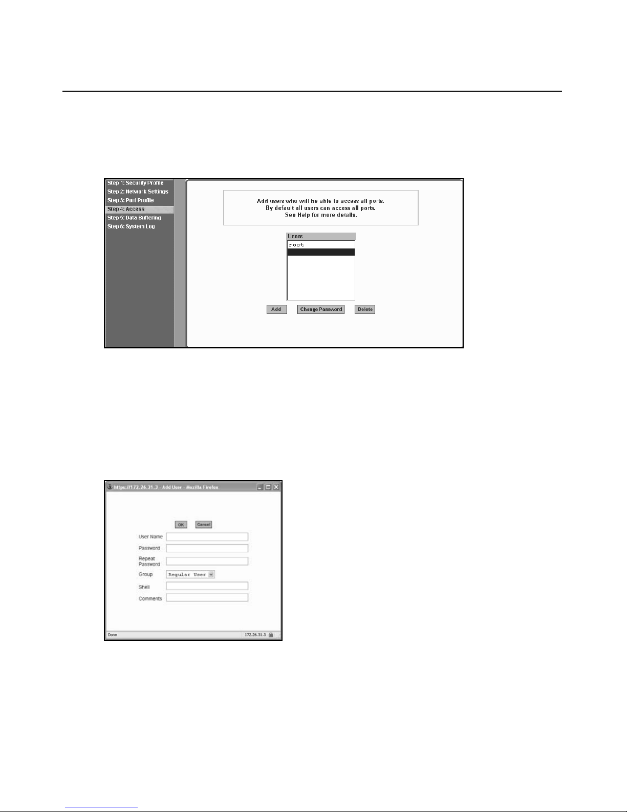
Chapter 5: Configur ing the ACS Console Server in Wizard Mod e 45
In addition, administrative privileges can be granted to added users by adding the user accounts to
an admin group, enabling them to administer the connected devices without the ability to change
the configuration of the console server. By default any user can access any port as long as a valid
user ID and password are used.
Figure 5.7: Wizard - Step 4: Access
The Access form lists the currently defined users and features Add, Change Password and Delete
buttons.
In the Users list by default, there is a root account that cannot be deleted. The root has access
privileges to all the Web Manager’s functionality as well as access to all the serial ports on the
console server.
Click the Add button. The following form is displayed.
Figure 5.8: Wizard - Step 4: Access Add User Dialog Box
Page 62

46 Cyclades ACS Advanced Console Server Installation/Adm in istratio n/User Guide
The following table defines the information required in the fields.
Table 5.5: Wizard - Add User Dialog: Field Names and Definitions
Field name Definition
User Name The username for the account being added.
Password and Repeat
Password
Group The choices in the Group menu are Regular User [Default] or Admin.
Shell Optional. The default shell when the user makes an SSH or a Telnet
Comments Optional notes about the user’s role or configuration.
The password for the account.
NOTE: To configure a user to be able to perform administrative functions, select
the Admin group. To define a new group, go to the Expert mode and select
Security - Users and Groups.
connection. Choices are: sh [Default] or bash.
If you click the Change Password button, the following dialog box appears.
Figure 5.9: Wizard - Step 4: Change Password Dialog Box
To add a user:
1. Select Step 3: Access. The Access form displays.
2. Click Add. The Add User dialog box appears.
3. Enter the username and password in the User Name and Password fields and enter the
password again in the Repeat Password field.
4. Select from the Group menu options.
a. To create a regular user account without administrator privileges, select Regular User
[Default] from the Group pull-down menu.
b. To create an account with administrator privileges, select Admin from the Group pull-
down menus.
NOTE: To define a new group, switch to Expert mode and select Security - Users and Groups.
Page 63

Chapter 5: Configur ing the ACS Console Server in Wizard Mod e 47
5. Enter the default shell in the Shell field (optional).
6. Enter comments to identify the user’s role or configuration in the Comments field (optional).
7. Click OK.
8. Click t he apply changes button.
To delete a user:
1. Select Step 3: Access. The Access form displays.
2. Select the username to delete.
3. Click Delete.
4. Click apply changes.
To change a password:
CAUTION: Leaving the default root password unchanged leaves the console server and connected devices
open to anyone who knows the default password and the console server’s IP address. For security reasons,
change the root password from the default tslinux as soon as possible.
1. Select Step 3: Access. The Access form displays.
2. Select the name of the user whose password you wish to change.
3. Click Change Password. The Change User Password dialog box displays.
4. Enter the new password in both fields and click OK.
5. Click apply changes.
Step 5: Data Buffering
Selecting Step 5: Data Buffering displays a form to allow logging the console data to a data buffer
file either locally in the console server or remotely to an external storage source such as an NFS
server or Syslog server. Once E nable Data Buffering is selected, the form displays a number of
fields. The displayed fields depends on whethe r selected Destination is Local or Remote.
The values set in this form apply to all serial ports. Data buffering allows a site to save a record of
all communication during a serial port connection session. You can set up data buffer files to be
stored either in local files on the console server’s Flash memory or on the hard disk of an external
server, such as an NFS or Syslog server.
Page 64

48 Cyclades ACS Advanced Console Server Installation/Adm in istratio n/User Guide
The following figure sh ows the for m when Enable Data Buffering is checked and the Destination is
set to Local.
Figure 5.10: Wizard - Step 5: Data Buffering [Local]
The following figure shows the form when the data buffering Destination is set to Remote.
Figure 5.11: Wizard - Step 5: Data Buffering [Remote]
Page 65

Chapter 5: Configur ing the ACS Console Server in Wizard Mod e 49
The following table provides description for each field whether local or remote destination
is selected.
Table 5.6: Wizard - Data Buffering Field Names and Definitions
Field name Definition
Destination Where the buffer files should be stored. Local, for example, Flash or Remote on
a server.
Mode For Local Destination - Select Linear for sequential files or Circular for non-
sequential format.
Local data buffering stores data in circular or linear mode. In circular mode, data is
written into the specified local data file until the upper limit on the file size is
reached; then the data is overwritten starting from the top of the file as additional
data comes in. Circular buffering requires the administrator to set up processes to
examine the data during the timeframe before the data is overwritten by new data.
File Size (Bytes) For Local Destination - Sets the value for this field to be greater than zero.
Record the timestamp If enabled, the system inserts a timestamp in the buffer.
NFS File Path For Remote Destination - Includes the path where the data buffer file should
be stored.
Show Menu Defines the options you wish to show in the menu of the buffer file.
The following table shows the differences between remote and local data buffering.
Tab le 5.7: Differences Beween Remote and Local Data Buffering
Option Description
Remote server Data is stored in files sequentially. The NFS server must be configured with the mount
point shared (exported). In linear mode, data is written into a continuous sequence of
files and the file spaces is not reused. The administrator needs to allow enough space
for the expected amount of data and take measures such as moving unneeded data files
off line, to ensure data does not outgrow the available space.
Local files Set a file size greater than zero. Make sure the file size does not exceed the space
available on the console server’s Flash memory. If needed, you can supplement the
Flash memory module by installing a Flash memory card (with an adaptor) or other
storage device in a PC card slot.
NOTE: You can perform advanced configuration in Expert mode including the option of setting up data buffering
separately for individual or groups of serial ports.
To configure data buffering:
1. Select Step 4: Data Buffering.
2. Click t he Enable Data Buffering checkbox. The Destination pull-down menu appears.
Page 66

50 Cyclades ACS Advanced Console Server Installation/Adm in istratio n/User Guide
3. Select a location for the data files from the Destination pull-d own menu (either Local or
Remote). Additional pull-down menus and fields appear, depending on which destination
is selected.
4. When the destination is local, perform the fo llowing steps.
a. From the Mode pull-down menu, select Circular or Linear data buffering.
b. Type a file size in bytes into the File Size (Bytes) field. The file size should be greater
than zero.
5. When the destination is Remote, perform the following steps.
a. In the NFS File Path field, enter the pathname for the mount point of the directory where
data buffer file is to be stored. For example, if the mount point directory’s pathname is /
var/adm/acslogs, enter
NOTE: The NFS server must already be configured with the mount point shared (exported) and the shared
directory from the NFS server must be mounted on the console server.
/var/adm/acslogs in the field.
b. To cause a timestamp to be saved with the data in the data buffer file, enable the Record
the timestamp in the data buffering file.
c. Select an option from the Show Menu pull- down menu . The ch oices are: show all options,
No, Show data buffering file only and Show without the erase options.
6. Click apply changes.
Step 6: System Log
Selecting Step 6: System Log displays a form for identifying one or more syslog servers to receive
syslog messages generated by the console server’s serial ports. Syslogging for IPDUs is also
possible if IPDU power management is configur ed.
The form displays as shown in the following figure.
Figure 5.12: Wizard - Step 6: System Log
Page 67

Chapter 5: Configur ing the ACS Console Server in Wizard Mod e 51
NOTE: To configure syslog with data buffering features for specific ports, switch to the Expert mode, Ports -
Physical Ports - Modify Selected Ports - Data Buffering.
Before setting up syslogging, make sure a pre-configured syslog server is available on the same
network as the console server. From the sy slog server administrator, o btain the the IP address of the
syslog server and the facility number for messages coming from the syslog server.
To add a syslog server:
This procedure assumes you have the IP address of the syslog server and the facility number for
messages coming from the console server.
1. Select Step 6: System Log. The System Log form displays.
2. From th e Facility Number pull-down menu, select the facility number.
3. In the New Syslog Se rver field, enter the IP address of a syslog server and then click the Add
button. (Repeat this step until all syslog servers are listed.)
4. The new server(s) appears in the Syslog Servers list.
5. Click apply changes.
To delete a syslog server:
1. From the Syslog Server list, select the syslog server that you wish to delete from the current
facility location and then click Delete.
2. Click apply changes.
Page 68

52 Cyclades ACS Advanced Console Server Installation/Adm in istratio n/User Guide
Page 69

CHAPTER
Applications
6
Configuring the Console Server in Expert Mode
Most applications require that you set th e Web Manager to Expert mod e. If you are in Wizar d mode
and need to perform advanced conf igurat io n, cl i ck the Ex pert bu tto n at the bo tto m of the l eft men u
panel to switch to Expert mode. If the Wizard button displays at the lower left of the screen, you are
in Expert mode.
Overview of menus and forms
53
Figure 6.1 shows a typical Expert mode screen. The top menu bar contains the primary commands
and the left menu panel contains the secondary commands. Based on what you select from the top
menu bar, the left menu panel selections change accordingly an d the form area may include tabs for
other options as shown.
Page 70

54 Cyclades ACS Advanced Console Server Installation/Adm in istratio n/User Guide
3
2
1
4
6
5
Figure 6.1: Expert Mode Screen Elements
Table 6.1: Expert Mode Screen Elements
Number Description
1 Top menu. Selecting any one of the top menu items will change the left navigation menu and form
areas to view status or configure the related console server options or parameters.
2 Left navigation menu. Selecting any of the left navigation menu items will change the information
and options in the form area.
3 Wizard/Expert button. If you are Expert mode, the button will say Wizard. If you are in Wizard mode,
the button will say Expert. Select the button to display the other mode.
4 Tabs. Tabs are additional buttons that change the content of the form area related to the item you
have selected in the left navigation menu. Tabs are displayed only with specific forms.
5 Form area. The form area contains the user -controlled text fields, checkboxes and pull-down
menus for configuring the console server.
6 Command buttons. The command buttons are common to all Web Manager screens and are used
to try changes, cancel changes, apply changes, reload pages or select the online help.
NOTE: The unsaved changes / no unsaved changes indicator at the far right is green (no unsaved
changes) when you have not made any changes that need to be saved, and flashes red (unsaved
changes) when you have made changes but have not selected apply changes.
NOTE: Procedures in this manual use shortcuts to tell how to get to Web Manager forms. For example, a step
telling the user to access the Outlets Manager form uses this convention, In Expert mode, select Applications-
IPDU Power Mgmt.-Outlets Manager.
Page 71

Applications Menu and Forms
The remainder of this chapter describes the Applications menu and the related forms. The
following table provides a description of the left menu panel and links to the detailed information
and associated procedure. If you are in Wizard mode and need to perform advanced configuration,
clicking the Expert button at the bottom of the left menu panel to switch the Web Manager to
Expert mode.
Connect
Using the Connect form, you can connect directly to the console server or to devices connected to
the serial ports.
Connecting to the console server
Clicking the Connect to ACS radio button and then clicking on the the Connect displays a Java
applet running an SSH session similar to the following figure.
Chapter 6: Applications 55
Figure 6.2: Expert - SSH session Java Applet
NOTE: SSH root access is enabled when the security profile is set to Moderate or Open. If a Secured security
profile is selected, you need to switch to a Custom security profile and enable allow root access option.
Connecting to devices connected to the serial ports
The Serial pull-down menu lists all the serial port numbers or the administrator-assigned aliases
that a user is authorized to access. Selecting a port number or alias and clicking Co nnect dis pl ays a
Java applet with a connection protocol for which the serial port is configured.
Page 72

56 Cyclades ACS Advanced Console Server Installation/Adm in istratio n/User Guide
If authentication is in effect for the port, you need to supply a username and password to log into
the device.
To connect to the console server:
This procedure logs you into the console server as a Regular User in an SSH session.
1. Go to Applications - Connect in Expert mode.
2. Click t he Connect to ACS radio button.
3. Click t he Connect button. A Java applet viewer appears.
NOTE: The login prompt is displayed whenever your security profile is set to Moderate or Open; otherwise, an
authentication form appears. You cannot authenticate unless you change the security profile to Custom and
enable allow root access.
To connect to a device through a serial port:
1. Select Applications - Connect in Expert mode.
2. Click t he Serial radio button.
3. Select a port number or alias from the Serial pull-down menu.
4. Click Connect. A Java applet viewer appears. If authentication is specified for the selected
port, you are prompted to log in. If not, you are logged in automatically.
IPDU Power Management
The ACS console server recognizes and supports all Cyclades PM series IPDUs as well as Avo cent
SPC Switched Rack PDU and ServerTech Switched CDU IPDU products through the common
interface. The console server’s PMD structure accommodates the differences in each of these
IPDUs to allow more flexibility with power management options .
NOTE: ServerTech IPDU installation, management and operation is license based through Avocent’s DSView®3
management software only.
Selecting IPDU Power Mgmt. displays five tabs in the form area, as follows:
• Outlets Manager
• Outlet Groups Ctrl
• View IPDUs Info
• Configuration
• Software Upgrade
NOTE: Using the IPDU power management forms, you can manage the power to connected devices only if the
serial port where the devices are connected is configured for power management.
Page 73

Chapter 6: Applications 57
Applications - IPDU Power Mgmt - Outlets Manager
On the Outlets Manager form under Applications-IPDU Power Mgmt., you can perform the
following tasks for all outlets on all connected IPDUs.
• Check the status of outlets.
• Turn outlets on and off.
• Cycle power.
• Lock outlets to prevent accidental changes in power state (Cyclades IPDUs only).
• Unlock the outlets (Cyclades IPDU s only).
• Assign an alias to the outlet (to identify the device for which it provides p ower) .
• Save the current configuration to Flash memory in the IPDU.
The following figure shows an Outlets Manager form.
Figure 6. 3 : E x pert - Applications - IPDU Power Mgmt . - Outlets Manage r
A list shows the port ID, IPDU ID, the model and vendor for IPDUs connected to ports that are
configured for power management. The Show button shows details about a selected IPDU. For
Avocent SPC power devices, the Out let Name, Minimum On Time, Minimum Of f Time and Wake
State are displayed. For Server Technology IPDUs, the Outlet Name, Post On Delay and Wake
State are displayed.
The following example shows the outlets and their states for a Cyclades IPDU connected to Port 2.
Page 74

58 Cyclades ACS Advanced Console Server Installation/Adm in istratio n/User Guide
Figure 6.4: Expert - Applications - IPDU Power Mgmt. - Outlets Manager - Show Outlets
The following table illustrates what each icon indicates.
Table 6.2: Expert - Outlets Manager Icons Description
Button Purpose
Yellow bulbs indicate an outlet is switched ON. Gray bulbs indicate an outlet is
switched OFF.
An opened padlock indicates that an outlet is unlocked. A closed padlock indicates that
an outlet is locked.
An orange Cycle button is active next to each outlet that is on.
Displays a dialog box to configure an Outlet Name and Post On Delay. Outlet names
must begin with a letter. Valid characters are letters, numbers, dash (-) and underscore
(_). The post on delay is the amount of time (in seconds) that elapses after the selected
outlet is turned on before another outlet is turned on.
Clicking the Edit button displays the dialog box for specifying Outlet Name and Post On Delay
(turn-on [PU] interval).
You can specify a name for the outlet, such as the server or device name and change the post on
delay (turn-on inte rval).
NOTE: The turn-on interval is the amount of time (in seconds) that elapses after the selected outlet is turned on
before another outlet can be turned on.
Third-party IPDU information displayed
SPC power devices will display the Outlet Name, Minimum On Time, Minimum Off Time and
Wake State.
Page 75

Chapter 6: Applications 59
ServerTech IPDUs will display Outlet Name, Post On Delay and Wake State.
To view status, lock, unlock, rename or cycle power outlets:
NOTE: For a group of outlets, the Cycle button operates only if all outlets of the group are turned ON.
1. Select Expert - Applications - IPDU Power Mgmt. - Outlets Manager. The Outlets Manager
screen appears with each IPDU listed.
2. Click t he Show button associated with the IPDU whose outlets you want to manage. A list of
outlets appears.
3. To switch an outlet (or an outlet group) on or off, click its light bulb icon.
NOTE: For Avocent SPC power devices or Server Technology IPDUs, an alert window prompts you that you may
need to refresh your browser to view the change in the Outlets Manager. Click OK and continue.
4. To lock or unlock an outlet (or an outlet group), click its pa d lock ico n.
NOTE: The outlet locking function is available on Cyclades IPDUs only.
5. To cycle power to an outlet, click the adjacent Cycle button.
6. To change the outlet’s name or the Post On Delay, click the adjacent Edit button. The Edit
Outlet dialog box appears.
a. To change the name assigned to the outlet, enter a new name in the Outlet Name field.
Names must begin with a letter. Valid characters are letters, numbers, dash (-) and
underscore (_).
b. To change the Post On Delay, change the default 0.50 number of seconds in the Post On
Delay field.
NOTE: An outlet name should not be changed if the new outlet name is used elsewhere.
7. Click OK.
8. Click t he Save Outlets State button (saves outlet states to the IPDU only).
9. Click apply changes.
NOTE: For Avocent SPC power devices or Server Technology IPDUs, an alert window prompts you that the
screen is automatically reloaded. Click OK and wait for confirmation that the page has been reloaded.
Applications - IPDU Power Mgmt. - Outlets Group Ctrl
An administrator can select Expert - Applications - IPDU Power Mgmt. - Outlet Groups Ctrl to
view the status of outlet grou ps and t ur n po wer off an d t hen on ag ain for an entire group of outlets.
NOTE: Outlet groups can be defined under PMD Configuration - Outlet Groups.
Page 76

60 Cyclades ACS Advanced Console Server Installation/Adm in istratio n/User Guide
Figure 6.5: Expert - Applications - IPDU Power Mgmt - Outlet Groups Ctrl
The Cycle button only can be used to cycle the entire group of outlets when all the outlets are on.
The following table describes the information available from the Outlet Groups Ctrl form.
Tab le 6.3: Expert - Outlet Groups Ctrl Information
Form Heading Description
Group Name:
Outlets
Group Ctrl
(IPDU and Port)
Individual Status Shows status icons (passive) for individual outlets within the group.
IPDU Group name followed by the individual outlets belonging to that group.
Group Ctrl shows status icons for defined group controls; (IPDU and Port)
shown in parentheses are the IPDU ID number and the serial port to which it is
connected on the console server. Status icons under the Group Ctrl heading
are active.
Applications - IPDU Power Mgmt. - View IPDUs Info
An administrator can select Exper t - Applications - IPDU Power Mgmt. - View IPDUs Info to view
information about each IPDU controlled by the console server. The Clear Max Detected Current
button resets the maximum detected current value. The Clear Max Detected Temperature button
resets the maximum detected temperature value.
Page 77

Chapter 6: Applications 61
Figure 6.6: IPDU Power Mgmt. - View IPDUs Info.
Tab le 6.4: Expert - Applications - Ipdu Power Mgmt - View IPDUs Info Description
Form Heading Description Example
ID Either a default name or administrator-configured ID appears. i1A (serial port 1)
Model The model of supported IPDU connected to the console server
at the designated port.
Number of Outlets The number of outlets on the IPDU. 8
Number of Inlets Total number of inlets available on the target IPDU 1
Syslog Whether syslogging has been configured for messages from
this IPDU.
Buzzer Whether a buzzer has been configured to sound when a
specified alarm threshold has reached.
Software Version IPDU firmware version installed on this IPDU. 1.9.0
Polling Rate The time interval at which the IPDU is polled by the PMD. 30000 ms
Default Voltage The nominal input voltage feeding the power device.
NOTE: Some power devices do not have the capability to read
the real input voltage using proper voltage sensors.
Power Factor The ratio of the real power to the apparent power; a number
between 0 and 1 that is frequently expressed as a percentage.
Real power is the capacity of the circuit for performing work in a
particular time. Apparent power is the product of the current and
voltage of the circuit.
Cyclades PM8 IPDU
SPC SPC8 Power
Control Device
ON when
syslogging is
configured
ON when the buzzer
is configured
127 V
0.707070
Page 78

62 Cyclades ACS Advanced Console Server Installation/Adm in istratio n/User Guide
Tab le 6.4: Expert - Applications - Ipdu Power Mgmt - View IPDUs Info Description (Continued)
Form Heading Description Example
Cycle Interval The time delay in seconds for powering up subsequent outlets
after a given outlet has been powered up.
Sequence Interval The time delay in seconds when powering up multiple outlets at
the same time (ServerTech IPDU only).
Current [value] The instantaneous current measured from the IPDU at
time.
this
Threshold Max. The maximum current that can be reached before an alarm is
initiated or the buzzer sounds, or
Max Detected The recorded maximum current reported by this IPDU (which
may include transients).
Temperature [value]
Detected
Max
Clear Max
Detected
Clear Max
Detected
Current
Temperature
The maximum temperature allowed in the IPDU before an
alarm is initiated or the buzzer sounds, or both (for IPDUs
equipped with temperature sensors only).
Button to reset the maximum detected current value.
Button to reset the maximum detected temperature value.
both.
1.3 A
20.0 A
1.3 A
To view and reset IPDU information:
1. Select Applications - IPDU Power M gmt. -View IPDUs Info. The View IPDUs Info screen
appears.
2. To clear the stored values, click the Clear Max Detected Current button or the Clear Max
Detected Temperature button.
Applications - IPDU Power Mgmt. - Configuration
An administrator can select Expert - Applications - IPDU Power Mgmt. - Configuration to
configure each configured IPDU.
NOTE: The operating parameters may differ depending on the make and model of IPDU.
Page 79

Figure 6. 7 : E x pert - Applications - IP D U Po wer Mgmt. - Configurati o n
Tab le 6.5: IPDU Power Mgmt Configuration Description
Shown Element Type Description
Chapter 6: Applications 63
ID: Heading Static heading shows current IPDU name and
assignment.
port
Model: Heading Shows the make and model of IPDU at the designated port.
ID Text field Enter whatever name you wish for this IPDU.
Polling Rate Number field Enter the polling time (how often the console server accesses
the IPDU for updates) in milliseconds. Default is 30000ms.
Enable Syslog Checkbox Click this checkbox to enable/disable syslog logging
(Cyclades IPDUs only).
Enable Buzzer Checkbox Click this checkbox to enable/disable IPDU alarm buzzer
(Cyclades IPDUs only).
Default Voltage Number field The nominal input voltage feeding the power device.
NOTE: Some power devices do not have the capability to read
the real input voltage using proper voltage sensors.
Power Factor Number field The ratio of the real power to the apparent power; a number
between 0 and 1 that is frequently expressed as a percentage.
Real power is the capacity of the circuit for performing work in
a particular time. Apparent power is the product of the current
and voltage of the circuit.
Current
Threshold Max (A)
Number field Enter the maximum amperes allowed by the IPDU before
generating an alarm (Cyclades IPDUs only). Exceeding the
entered threshold maximum current will also prevent the IPDU
from powering up again until the problem is
corrected.
Page 80

64 Cyclades ACS Advanced Console Server Installation/Adm in istratio n/User Guide
Tab le 6.5: IPDU Power Mgmt Configuration Description (Continued)
Shown Element Type Description
ID: Heading Static heading shows current IPDU name and
port assignment.
Total Load
Max (A)
Total Load
Min (A)
Number field Enter the maximum amperes allowed by the IPDU before
generating an event. (Always enabled, SPC and ServerTech
IPDUs only.)
Number field Usually set for zero, setting this field to a minimum value for
current (amperes) is useful for monitoring if a device or
devices lose power unexpectedly, which will generate an
event (SPC and ServerTech IPDUs only).
Applications - IPDU Power Mgmt. - Software Upgrade
An administrator can select Expert - Applications - IPDU Power Mgmt. - Software Upgrade to
upgrade software (firmware) for Cyclades PM IPDUs only. The screen shows the currently
installed software version on the selected IPDU. If a newer software version is available, you can
download new software for your IPDU using the following procedure.
To download Cyclades IPDU software:
Use this procedure to download software from the Avocent website.
1. Type
NOTE: Your web server must be in the same subnet as the console server.
2. Compare the displayed version number to the version shown in the Applications - IPDU Power
3. If a newer firmware version is available, click the Firmware link associated with the
4. After the download completes, copy the file into the /tmp folder and rename it with the
http://www.avocent.com/web/en.nsf/Content/Cyclades_Download-PM in your
browser address field to open the Downloads page.
Mgmt. - Software Upgrade screen.
appropriate version. The download starts.
filename pmfirmware.
To upgrade software on a Cyclades PM IPDU [Expert]:
1. Select Power Mgmt. - Software Upgrade. The Software Upgrade screen is displayed.
2. Click Refresh. If a /tmp/pmfirmware exists containing a more recent version of the PM
firmware than the one currently installed, an Update button is displayed.
3. Click Update.
4. Click apply changes.
Page 81

To upgrade software on non-Cyclades IPDUs:
Avocent SPC power devices are not user upgradable. For Server Technology IPDUs, upgrades
must be done thro ugh a network port. Contact Server Techno l ogy s upp ort to check if new software
is available and for information on how to upgrade the device.
Expert - Applications - PMD Configuration
When an administrator selects Expert - Applicati ons - PMD Config uration, the foll ow ing th ree tabs
appear:
• General
• Outlet Groups
• Users Management
An administrator can use these tabs to configure the username and password for IPDUs, create
groups and authorize users and groups to access specific outlets.
To find the IPDU ID [Expert]:
1. Select Expert - Access - IPDU Power Management - View IPDUs Info.
2. Note the string in the ID field.
Chapter 6: Applications 65
Applications - PMD Configuration- General
An administrator can select Expert - Applications - PMD Configuration - General to configure a
username and password for each supported IPDU type. The fields are labeled: Cyclades (for
Cyclades PM IPDUs), SPC (for Avocent SPC power devices) and Server Tech (for supported
Server Technology IPDUs). The username and password are used to authenticate communication
between the console server and the IPDU. If the IPDU username and password are changed in the
IPDU firmware, the username and password must be changed in this screen so the console server
can use the correct username and password to communicate with the IPDU.
Figure 6.8: Applications - PMD Configuration
Page 82

66 Cyclades ACS Advanced Console Server Installation/Adm in istratio n/User Guide
Applications - PMD Configuration- Outlet Groups
An administrator can select Expert - Applications - PMD Configuration - Outlet Groups to
configure outlet groups.
Figure 6.9: PMD Configuration - Outlet Groups
Any configured outlet groups are listed in the Group column, followed by the string used to
identify the group during configuration (in the form IPDU_ID[outlets] as shown). The Add, Edit
and Delete buttons are used to configure the outlet groups.
Specify groups of outlets using the following format:
IPDU_ID[outlets]
Where IPDU_ID is the name configured for the IPDU (such as ilA) and outlets are numbers
separated with commas or with dashes (to indicate a range), as in the following example:
ilA[1,2,5-15]
You can assign outlets from more than one IPDU to a group by using commas to separate them.
The following example defines an outlet group for two IPDUs, one named ilA and the other ilB:
ilA[1,5-8],ilB[1,3,4]
For more information, see Conventions used to identify outlets on page 10. See also Applications PMD Configuration- General on page 65 to find out the IPDU ID.
To configure an outlet group:
1. Click t he Add button. The Add/Edit Outlet Groups dialog box appears.
2. In the Group field, enter the name of the group you want to add or edit the existing name.
3. In the Outlets field, add the IPDU ID followed by the specific outlets to assign to the group in
brackets. For example, i1A[ 1,5-8] creat es a group of out lets numbered 1 , 5, 6, 7 and 8 on IPDU
ID ilA. You can assign more than one IPDU to the group, with a comma between each IPDU.
4. Click OK.
Page 83

To delete an outlet group:
1. Click t he Delete button.
2. Select the group name you want to delete.
3. Click OK.
Applications - PMD Configuration- Users Management
An administrator can select Expert - Applications - PMD Configuration - Users Management to
configure users to access outlets.
Chapter 6: Applications 67
Figure 6.10: PMD Configuration - Users Management
The listed users are authorized to access and control the outlets specified under the Outlets heading.
To authorize a user for IPDU power management:
1. Select Expert - Applications - PMD Configuration - Users Management.
2. Click Add. Add/Edit PM Users dialog box appears.
3. In the User field, enter the username.
4. In the Outlets field, enter the group name, IPDU number and outlets that the user can control.
5. Click OK.
Outlet entry conventions
In the most basic case, only the IPDU’s ID and the outlets named in brackets following the ID are
needed to specify which outlets will be accessible by the user. It is sometimes desirable to have
more control over outlet groups, daisy-chained IPDUs or which serial port on the console server
Page 84

68 Cyclades ACS Advanced Console Server Installation/Adm in istratio n/User Guide
must be used for the permissions to be valid. The following table shows the prefix, suffix and
syntax information used to specify outlets in various circumstances.
Table 6.6: Conventions Used in Specifying Outlets for User Accessibility
Symbol T ype Signifies Example
$ Prefix Group $Cyclades_PDU would specify the Cyclades_PDU outlets group, and
that the user specified has permission to control that group of outlets.
!ttyS Prefix Serial port !ttyS2 would specify serial port 2 on the console server would be the
only one the user would have permissions to use for IPDU
management, regardless of the IPDU or outlets specified.
A through Z Suffix Order of
IPDU in
daisy-chain
NOTE: Daisy-chained IPDUs (A, B, C, etc.) create sequentially numbered outlets across IPDUs.
!ttyS2B[1-8] would indicate that serial port 2 on the console server
would be used to control the second IPDU in the chain (B), followed by
the outlet or range of outlets on that IPDU with user permissions.
The following figure shows two daisy-chained (master/slave) IPDUs connected to serial port 2 on
the console server.
Page 85

Chapter 6: Applications 69
123
4
Figure 6.11: Various Outlet Designations on Daisy-chained IPDUs
Table 6.7: Outlet Designations on Daisy-chained IPDUs (PM10 shown)
Number Description
1 ACS console server with serial connection shown at Port 2. The IPDU can be connected to any
serial port.
2 IPDU A. This is the first IPDU in the chain.
3 IPDU B. This is the second IPDU in the chain.
4 Example of an outlet that has been renamed. See the following table for details.
Page 86

70 Cyclades ACS Advanced Console Server Installation/Adm in istratio n/User Guide
There are three different methods to specify the outlet named “myoutlet” on IPDU B. The
following table describes the three methods.
T a ble 6.8: Methods for Specifying a Specific Port on Daisy-chained IPDUs
Method Description
By name If the outlet has been assigned a name, such as “myoutlet,” entering myoutlet
is sufficient and no other path name is needed.
By IPDU then outlet Entering IPDUB[3] will designate the same outlet.
By serial port then outlet If the outlet has been assigned a name, such as “myoutlet,” entering myoutlet
is sufficient and no other path name is needed.
All three methods will designate the same outlet. Note that when a specific IPDU is n a m e d in the
chain, the outlet number reverts to the IPDU-specific outlet number (3). When only the serial port
is used, the IPDU chain is seen as a continuous series of outlets numbered accordingly.
Expert - Applications - T erminal Profile Menu
An administrator can select Expert - Applications - Terminal Profile Menu to configure a terminal
command menu. This menu is used if a terminal is connected to one of the serial ports and the serial
port is configured as a local terminal. A connection to a serial port configured as a local terminal
launches a session on the terminal with access to the Linux commands on the console unless you
configure a menu here.
Figure 6.12: Expert - Applications - Terminal Profile Menu
The menu can contain any command recognized by the Linux operating system on the console
server. The most common use of this feature is to create multiple menu options for launching SSH
sessions on several remote hosts.
Page 87

Chapter 6: Applications 71
For example, you can create a menu called SSH to Servers with options that launch SSH
connections to several servers, as shown in the following example.
Figure 6.13: Expert - Terminal Profile Menu Example
To create a menu for a local server terminal:
1. Select Expert - Applications - Terminal Profile Menu. The Terminal Profile menu appears.
2. Enter a title for the menu in the Menu title field.
3. To edit an existing menu option, select th e Action Name from the table and then click Edit.
4. To add a new menu option, click Add. The Add Option dialog box appears.
a. Enter a title for the menu option in the Title field.
b. Enter an action or command to be executed when the user clicks the menu option in the
Action/Command field.
5. Click OK.
6. Click apply changes.
Page 88

72 Cyclades ACS Advanced Console Server Installation/Adm in istratio n/User Guide
Page 89

CHAPTER
7
This chapter describes the Network menu and related forms. The following table provides a
description of the left menu panel.
Table 7.1: Expert - Network Menu Description s
Menu Selection Use This Menu to:
Host Settings Configure the network parameters such as Host Name, IP addresses,
73
Network Menu and For ms
DNS services, Gateway and Bonding. Additional tabs are displayed for
IPv4 and IPv6 protocol configuration.
Syslog Configure how the console server will handle its syslog messages. The
console server generates syslog messages related to users connecting
to ports, login failures and other information that can be used for audit
and control purposes.
PCMCIA Management Configure the optional PC cards. The console server supports several
PC cards including modem, ISDN, GSM, CDMA, wireless LAN,
Ethernet, CompactFlash and hard disk drives for data buffer storage. Go
to http://www.avocent.com for a list of supported PC cards.
VPN Connections Configure one or more VPN connections to other systems or console
server attached devices.
SNMP Configure SNMP with community names, OID and usernames. This
section and the dialog boxes guide you to configure the required
parameters.
Firewall Configuration Configure static IP tables and how packets should be filtered.
Host Table View information about the local network environment.
hosts; create, edit and delete hosts.
Static Routes Manually add routes. Static routes are a very quick and effective way to
route data from one subnet to different subnets.
View table of
Page 90

74 Cyclades ACS Advanced Console Server Installation/Adm in istratio n/User Guide
Host Settings
Use the Host Settings form to set up basic host netw ork configuation for the types of Internet
protocols you need. The three tabs across the top of the form are General, IPv4 and IPv6.
General host settings
When you select Network - Host Settings the following form is displayed.
Figure 7.1: Expert - Network - Host Settings
The following table describes the fields on the Network - Host Settings form.
Table 7.2: Network - Host Settings General Tab Form Field
Field name Field type Description
Mode Pull-down menu Select Internet protocol from IPv4, IPv6 or Dual-Stack, which allows
concurrent use of both IPv4 and IPv6 protocols.
NOTE: Selecting the IPv4 tab will enable IPv4 protocol configuration
and disable IPv6. Selecting the IPv6 tab will enable IPv4 protocol and
will disable IPv4. Selecting Dual-Stack will enable configuration for
both IPv4 and IPv6 protocols.
Host Name Text field Enter the fully qualified domain name identifying the specific host
server on the network.
Console Banner Text field Enter a text string designed to appear on the console when logging
into or exiting from a port as a way to verify and identify the port
connection.
Page 91

Chapter 7: Network Menu and Forms 75
Table 7.2: Network - Host Settings General Tab Form Field (Continued)
Field name Field type Description
DNS Service
Primary DNS
Server
Text field
Enter the address of the of the domain name server.
Secondary DNS
Server
Domain
Name Text field Enter the name of the host domain.
Bonding Checkbox Click Enabled to enable bonding. Bonding provides redundancy for
NOTE: If you have set IP Filtering rules before bonding is activated, the interface reference in the firewall
configuration will be eth0. You need to change the interface to bond0 in order to reference the bonded interface.
Text field
Enter the address of the backup domain name server, if used.
the Ethernet devices using the standard Ethernet interface as the
primary mode of access and a PC card as a secondary mode of
access.
If bonding is enabled, the following values should be set:
Miimon - The interval in which the active interface is checked to see if
it is still communicating (in milliseconds).
Updelay - The time that the system will wait to make the primary
interface active after it has been detected as up (in milliseconds).
Disabling and enabling IPv4 or IPv6 protocols
The ACS console server allo ws yo u t o p ermanently enable or disable either IPv4 or IPv 6 pr ot oco l s
during configuration from the Network - Host Settings - General Mode pull-down menu.
Disabling IPv4
If you disable IPv4, configuration of IPv4 addresses will not be allowed. A warning m e ssage will
be displayed advising you that services not supporting IPv6 will b e unavailable. The IPv4 tab will
be disabled.
NOTE: If services not supporting IPv6 are needed, you will have to select Dual-Stack (IPv4 and IPv6) and those
services will be available only for IPv4.
Disabling/Enabling IPv6
If you disable IPv6, configuration of IPv6 addresses will not be allowed and the IPv6 tab will b e
disabled. If you change IPv6 from disabled to enabled, a warning message will be displayed
advising you that some services not supporting IPv6 will be unavailable and that you will have to
configure those services supporting IPv6 for them to work properly.
NOTE: If services not supporting IPv6 are needed, you will have to select Dual-Stack (IPv4 and IPv6) and those
services will be available only for IPv4.
Page 92
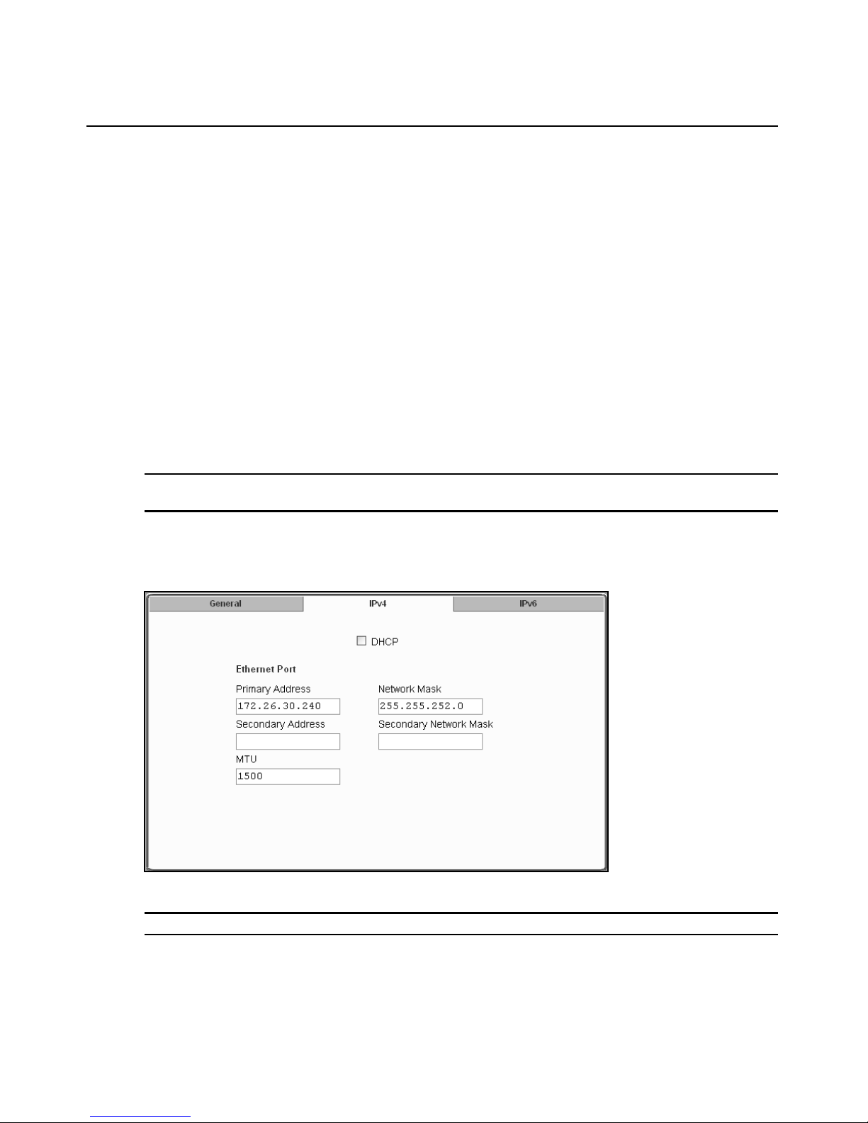
76 Cyclades ACS Advanced Console Server Installation/Adm in istratio n/User Guide
When IPv6 is enabled, you will need to configure the following parameters and services to work in
IPv6 mode:
• network parameters
• authenti cation servers
• DNS
•SNMP
•SNMP traps
•syslog
•NTP
• VPN connections (if any)
• host table addresses
• firewall configuration
• static routes (if any).
NOTE: Both Wizard and Expert modes of the web interface can be used to configure network parameters.
Beyond the network parameters stated above, other services must be configured in Expert mode.
IPv4 settings
When you select Network - Host Settings - IPv4, the following form is displayed.
Figure 7.2: Expert - Network - Host Settings - IPv4 (DHCP disabled)
NOTE: If DHCP is checked, the rest of the form is disabled and will not be displayed.
Page 93

Check DHCP (checked by default) to have the console server pull network parameters from the
DHCP server. If this box is not checked (DHCP disabled), the following fields are displayed in the
form.
T a ble 7.3: Network - Host Setting - IPv4 Field Defint ions
Field name Field Definition
Primary Address Enter the primary IPv4 address of the ACS console server.
Network Mask Enter the 32-bit number used to group IPv4 addresses together or to
Secondary Address The secondary IPv4 address of the console server unit. By configuring a
Secondary Network Mask Optional.
MTU Maximum Transmission Unit used by the TCP protocol.
IPv6 settings
Chapter 7: Network Menu and Forms 77
indicate the range of IPv4 addresses for a subnet.
second IPv4 address, the unit will be available for more than one network.
When you select Network - Host Settings - IPv6, the following form is displayed.
Figure 7.3: Expert - Network - Host Settings - IPv6
Page 94

78 Cyclades ACS Advanced Console Server Installation/Adm in istratio n/User Guide
The following table provides definitions of the IPv6 form fields.
T a ble 7.4: Network - Host Setting - IPv6 Field Defint ions
Field name Field Definition
DHCPv6 Select None, DNS, Domain or DNS-Domain from the pull-down menu.
Choosing one selects the options for the information that will be retrieved
from the DHCPv6 server.
• None: No further data is retrieved from the server.
• DNS: The DNS server IP address is retrieved from the server.
• Domain: The domain path is retrieved from the server.
• DNS-Domain: Both the DNS server IP address and the domain path are
retrieved from the server.
Method Select Stateless only, Static or DHCP methods from the pull-down menu for
the desired Ethernet port configuration method. Selecting one of these
options chooses the method used to obtain and configure IPv6 addresses.
• Stateless only: IPv6 local addresses will be obtained dynamically from the
IPv6 router in the local network. This method should be used only if the
other two methods are unavailable. Local IPv6 addresses obtained by the
router cannot be used outside of the local network.
• Static: This method configures a static IPv6 address and its prefix length
for the interface.
• DHCP: The IPv6 address and its prefix length will be obtained
dynamically from a DHCPv6 server.
Static Address Enter the static IPv6 or IPv4 address of the Ethernet port. If entering an IPv6
address, enter both the IPv6 address and its prefix length:
<ipaddress>/<prefix_length>
Configuring a static IPv6 address is available only if the IPv6 Method
selected is Static.
IPv6 Ethernet interfaces
All Ethernet interfaces must be either configured or dynamically assigned, including the bonding
interface. Ethernet IPv6 can be dynamically assigned by a DHCPv6 server.
IPv6 serial interfaces
All serial interfaces can be configured with IPv6 addresses (port IP alias).
IPv6 PPP interfaces
All PPP interfaces can be either configured or dynamically assigned with IPv6 addresses. This
includes all interface types you might configure to use PPP protocol, such as serial ports with
extended modems, analog modem PC cards and ISDN PC cards.
Page 95

Chapter 7: Network Menu and Forms 79
Other interfaces
All interfaces other than Ethernet, bonding and PPP will also be configured with IPv6 addresses,
including all sub-interfaces and virtual interfaces such as VPN tunnels (static IPSec tunnels). The
following list shows the network services that will be configured to support the IPv6 protocol:
• Access to DNS servers
•SNMP
• Sending SN MP trap
• Remote authentication (except to NIS)
• Access to hosts
• Stateful and stateless packet filtering (firewall)
• Static routes
• Sending messages and events to SMTP servers
• Sending data to data buffering servers
• Access to NTP server
• FTP for configuration backup
• FTP for firmware upgrade
NOTE: Virtual ports (virtualization) are not supported by IPv6.
To configure host settings [Expert] from the General form:
1. Go to Network - Host Settings. The Host Settings - General form appears.
2. Select Dual-Stack, IPv4 or IPv6 from the Mo de pull-dow n menu.
NOTE: If Dual-Stack is selected, both the IPv4 and IPv6 tabs will remain active and will run concurrently.
Selecting IPv4 will disable the IPv6 tab, and selecting IPv6 will disable the IPv4 tab in the Host Settings form.
3. Enter the name assigned to the IP address of the console server in the Host Name field.
4. Enter a console banner in the Console Banner field.
5. Enter the Primary DNS Server IP address.
6. Enter the Secondary DNS Server IP address, if used.
7. Enter the domain in the Domain Name field.
8. To enable Bonding (optional), click Enabled. If Bonding is not desired, leave Enabled
unchecked and go to Step 10.
NOTE: If Bonding is enabled, you may have to scroll down to see additional entries for Miimon and Updelay.
9. If you enabled Bonding, check the values for Miimon and Updelay and change them if
necessary.
10. When finished, click apply changes.
Page 96

80 Cyclades ACS Advanced Console Server Installation/Adm in istratio n/User Guide
To configure IPv4 protocol:
1. If IPv4 is enabled (tab is active) select the IPv4 tab. The IPv4 form will be displayed.
2. If configuring IPv4 using DHCP is desired, click the DHCP checkbox.
NOTE: If DHCP is enabled, all other fields on the form will not be displayed.
3. Under Ethernet Port, complete or edit the following fields as necessary.
a. Enter the IP address of the console server in the Primary Address field.
b. Enter the netmask in the Network Mask field.
c. Enter the address of the secondary console server in the Secondary Address field, if used.
d. Specify the network mask of the secondary IP in the Secondary Network Mask field.
e. Specify the desired maximum transmission unit in the Maximu m Transm ission Unit field.
4. When finished, click apply changes.
To configure IPv6 protocol:
1. If IPv6 is enabled (tab is active), select the IPv6 tab. The IPv6 form will be displayed.
2. From the DHCPv6 pull-down menu, select none, DNS, Domain or DNS-Domain. If DHCP is
selected, then the DHCP options will define the address configuration information is retrieved
from the DHCPv6 server. DHCP options are:
• none (only the IP address will be retrieved)
• DNS (the DNS address will be retrieved from the DHCPv6 server)
• Domain (the domain path will be retrieved from the DHCPv6 server)
• DNS-Domain (both DNS server and domain path will be retrieved from the DHCPv6
server)
NOTE: If either DNS or DNS-Domain is selected, DNS Service and its associated fields will not be displayed.
3. Under Ethernet Port, complete or edit the following fields as necessary.
a. Choose your configuration method from the Method pull-down menu. Choices are
Stateless only, Static or DHCP.
NOTE: It is recommended that Stateless only be used only when none of the other methods is available. This
means that local configuration from the local router and only the link_local address will be available to the ACS
console server.
b. If the DNS Service fields are active (none or Domain DHCP selected in Step 2) and Static
has been selected under Ethernet Port, enter the Primary DNS serv er IP address. If ther e is
a backup DNS server, enter the the add ress of th e s econd ary DNS serv er in the Secon dary
DNS server field.
4. When finished, click apply changes.
Page 97

Syslog
When Network - Syslog is selected, the form shown in the following figure appears.
Chapter 7: Network Menu and Forms 81
Figure 7.4: Expert - Network - Syslog
You can use the Syslog form to configure h ow the console ser ver handles system log ged messages.
The Syslog form allows you to perform the following:
• Specify one or more syslog servers to receive syslog messages related to ports.
• Specify rules for filtering messages.
The top field on the form CAS Ports Facility is used to tell console server where to send
syslog messages.
You can specify a facility number for the messages from serial ports. Obtain the facility numbers
from the syslog server’s administrator.
You can send the syslog messages:
Page 98

82 Cyclades ACS Advanced Console Server Installation/Adm in istratio n/User Guide
• To the console port for logging the messages even if no user is logged in
• To all sessions where the root user is logged in
• To one or more syslog servers.
You can add or remove syslog servers.
The bottom part of the form has filtering rules for specifying which types of messages are
forwarded based on the following criteria:
• Severity level: Emergency, Alert, Critical, Error, Warning, Notice, Info, Debug.
• Category CAS log; Data Buffering log; Web log or System log.
To configure syslogging for serial ports and specify message filtering:
1. Go to Network - Syslog in Expert mode. The Syslog form appears.
2. Select a facility number for messages generated by serial ports by selecti ng th e number from
the CAS Ports Facility pull-down menu.
3. Select a destination for the syslog messages by clicking the checkbox next to one or all of the
options: Console, Root User or Server.
4. Add a syslog server to the Syslog Servers list, by entering its IP address in the New Syslog
Server field and clicking Add.
5. Configure the message filtering as per your requirements.
6. Click apply changes.
PCMCIA Management
When Network - PCMCIA Management is selected the following form appears.
Figure 7.5: Expert - Network - PCMCIA Management
You can use the PCMCIA management form to configure the following types of PC cards:
• 10/100 BaseT Ethernet
• 802.11b Wireless LAN
• V.90 Modem
Page 99

Chapter 7: Network Menu and Forms 83
•ISDN
•GSM
•CDMA
• CompactFlash
• IDE Hard Disk
NOTE: You can insert a card at any time and the corresponding driver should load automatically. Before
removing a card, however, you must use the Web Manager to eject the card and stop the system from using the
card. If you install an IDE PC card in a slot, it automatically mounts and no configuration is necessary through
this form.
NOTE: The console server supports GPRS and 1xRTT PC cards through a Generic Dial-Out application. For
Configuration details refer to the Cyclades ACS Command Reference Guide.
Visit the Avocent web site at http://www.avocent.com for a list of supported PC cards.
To configure a PC card:
1. Go to Network - PCMCIA Management. The PCMCIA Management form appears.
2. Insert the card into the PC cardslot on the front of the console server and click the Insert button
for the slot in which you installed the PC card.
3. Click OK in the dialog box that displays.
NOTE: You can insert a card at any time and the corresponding driver should load automatically. Before
removing a card, you must use the Web Manager to eject the card and stop the system from using the card. If
you install an IDE PC card in a slot, it automatically mounts and no configuration is necessary through this form.
The card information appears under the Card Type column as shown in the following figure.
Figure 7.6: PC Card Type by Slot
4. Click t he Configure button.
5. The Slot dialog box appears.
6. Select t he desired PC card type fr om the pull-down menu.
7. Follow the steps that correspond to the type of the PC card you have installed.
Page 100

84 Cyclades ACS Advanced Console Server Installation/Adm in istratio n/User Guide
Configuring a modem PC card
You can use the PCMCIA Management for m under Network to enable a remote user to call into the
console server through an installed modem PC card. When you select Modem from the pull-down
menu, the dialog box for the corresponding card slot appears.
NOTE: For all supported PC cards that include a checkbox for Authentication One Time Passwords Required, a
full description of the One Time Password (OTP) feature can be found in the Cyclades ACS Command
Reference Guide.
The following table provides a brief description of the fields available in the Modem dialog box.
Tab le 7.5: Modem Dialog Box Fields
Field Name Definition
[PC Card] Pull-down menu to select the type of PC card you are using.
PPP Checkbox to enable point-to-point protocol.
Local IP The local IP address of the PC card.
Remote IP The remote IP address of the PC card.
Call Back Checkbox to enable the callback security feature.
Phone Number The phone number that the console server uses to call back.
Authentication One Time
Password Required
Checkbox if OTP is required for authentication by way of the PC modem.
If you click the PPP checkbox, additional fields for a local and remote IP address and a Call Back
checkbox appear.
If you enable Call Back, the Phone Number field appears on the Slot dialog box.
NOTE: The syslog to user root must be disabled before root users log in using the modem PC card. Failure to do
so will cause all syslog information to be sent to dev/ttyM1. This will overload the buffer, rendering it unusable. If
this happens, the modem PC card will then be unable to answer subsequent calls.
To configure a modem PC card:
1. Install the modem card and select Modem from the pull-down menu on the PCMCIA
Management form.
2. To enable PPP, perform the following steps:
a. Check the PPP checkbox.
b. The Local IP and the Remote IP fields and the Call Back checkbox appear on the Slot
dialog box.
c. Enter an IP address in the Local IP field, if desired.
 Loading...