

Page 1
formerly
AVerMedia In formation
HVC310/HVC110 Installation Guide
Thank you for choosing AVer video conferencing solutions. This hardware installation guide serves as a reference for making the connections
needed to get your new system up and running as quickly as possible.
1. Before making the connections
Make sure all devices are powered o. Follow the illustrated connection diagrams below to ensure all essential cables
are properly connected. Refer to the user manual of the device you are connecting to the video conferencing system.
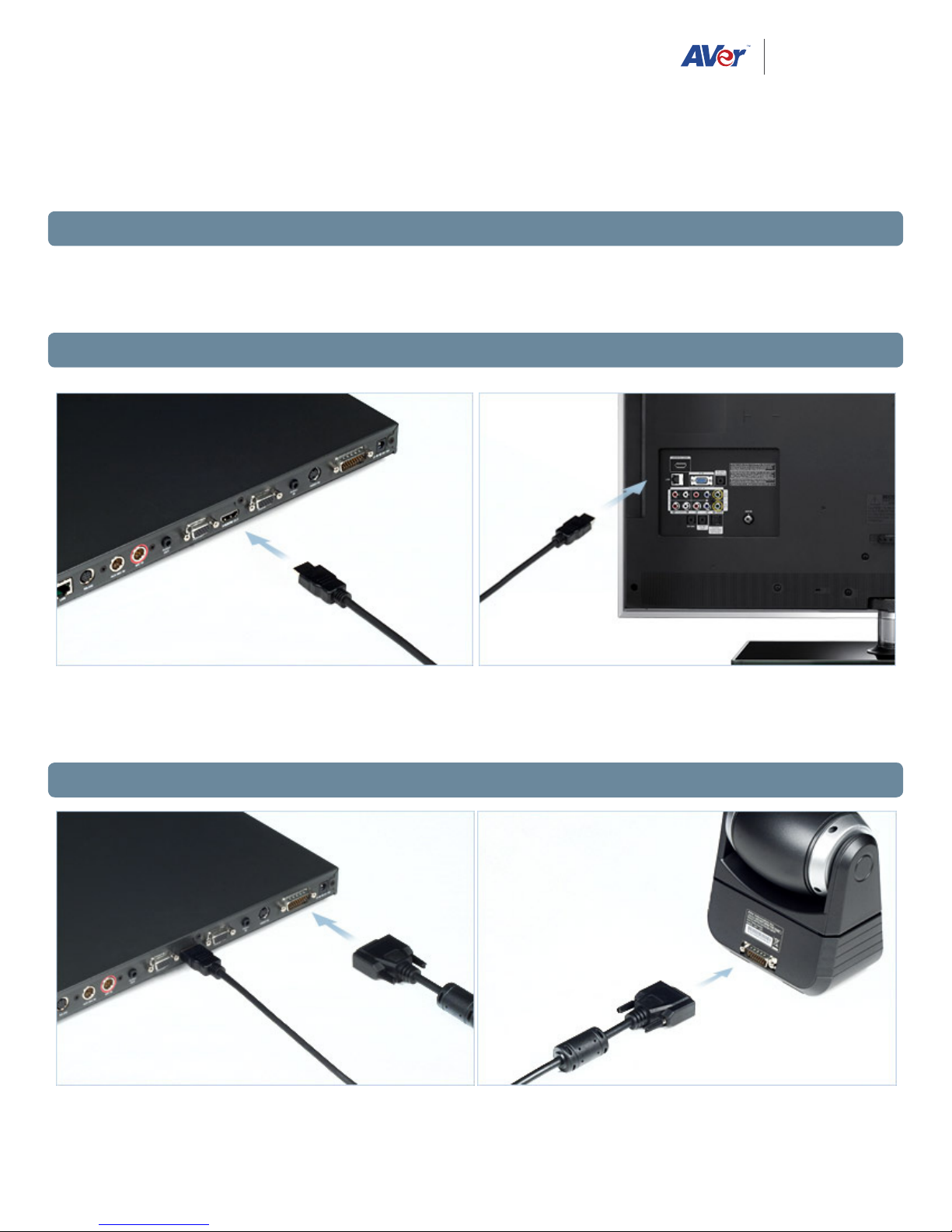
2. Connecting the display device(s)
Connect one end of the HDMI cable to the HDMI OUT port on the back of the codec, and the other end to your HDMI
enabled display device. If you are using dual displays, connect the VGA cable to the VGA OUT port on the codec and
the VGA input of your second display.
3. Connecting the camera
If you are using the included 26-pin D-sub camera cable, connect one end to CAMERA IN port on codec and the other
end to the camera
1
Page 2
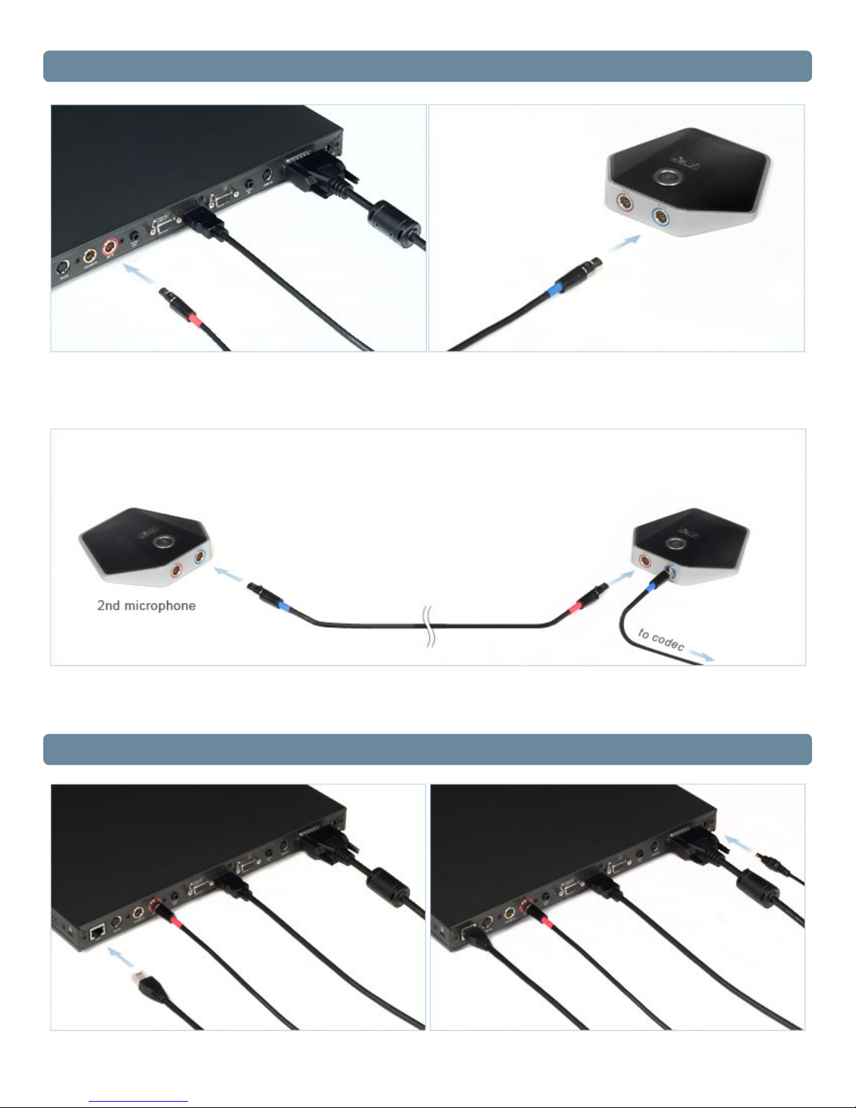
4. Connecting the microphone(s)
To connect the directional microphone, connect the red end of the 6-pin mini XLR cable to the red MIC IN port on the
codec and the blue end to the blue MIC OUT port on the microphone.
If you are connecting multiple mics, daisy-chain them by connecting the cables matching the colors (red cable end to
red mic port, etc.)
5. Connecting the LAN (internet) and the power
2
Page 3

Using the supplied RJ-45 ethernet cable, connect one end to the LAN port on the codec and the other end to your
network. Make sure to connect to an IP-based network.
Connect the power adapter to any standard 100V~240V AC power outlet, then plug the power into the system. Only
use the supplied 19V power adapter to apply power to the video conferencing system.
6. Connecting external speakers (optional)
If you plan to use external speakers (and not the HDMI cable for audio), connect them to the back of the codec using
the 3.5mm AUDIO OUT port. Powered speakers are recommended when using an external speaker system.
7. Connecting an auxiliary microphone (optional)
If you plan to use an external or auxiliary mic, connect it to either the 3-pin mini XLR port on the codec labeled AUX
MIC IN, or the 3.5mm AUDIO IN port. Please note that when using a mic on either of these ports, it will disable any
microphones plugged into the red MIC IN port. A powered mic is required when using the 3.5mm audio input.
Contact Support
Tel: (877)528-7824
Email: support.cpdusa@aver.com
www.averusa.com/communication
©2011 by AVer Information Inc. All rights reserved.
No part of this document may be reproduced or transmitted in any form, or by any means without the prior written permission of AVer
Information Inc. AVer Information Inc. reserves the rights to modify its models, including their characteristics, specifications, accessories and
any other information stated herein without notice. The official printout of any information shall prevail should there be any discrepancy
between the information contained herein and the information contained in that printout. “AVer” is a trademark owned by AVer Information
Inc. Other trademarks used herein for description purpose only belong to each of their companies.
3
 Loading...