

Page 1

2
HVC-Series
Video Conferencing System
Quick Installation Guide
Page 2
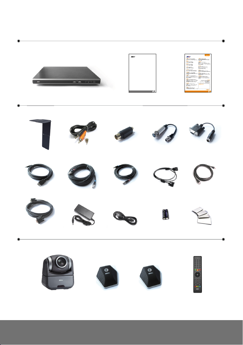
Package Contents
1 2 3
2
Quick Instal lati on Guide
HVC-Series
Video Con feren cing Syst em
5 6
9 12
15 17
7
10 13
16 18
8
11
14
4
19 20 21 22
Page 3
ENGLISH
2 31
A
B
C
A
B
C
4
19
20
21
22
5
10
15
6
11
16
7
12
17
8
13
18
9
14
1. Main System
2. Quick Installation Guide
3. Warranty Card
4. L-Bracket (camera stand) *Optional
5. 3.5mm to RCA cable
6. S-Video to Composite Converter
7. 3-Pin Standard XLR Adapter
8. DB9 RS232 Converter
9. HDMI Cable
10. 6 Pin Mini XLR MIC Cable (10M)
11. 6 Pin Mini XLR MIC Cable (5M)
12. 26-Pin D-Sub Camera Cable
13. RJ-45 Cable
14. VGA Cable
15. Power Adapter
16. Power Cord
17. AAA Batteries
18. Velcro
19. Camera
(Optional for HVC130/110)
20. Mic
21. Mic (Optional for HVC130/110)
22. Remote Control
Page 4

Remote Control
Zoom
Layout
Vol
Presentation
Record
Mute
Image Ctrl Preset Snapshot Dual
Far/ Near
Input
16:9/4:6
Back
Call
Hang up
Info Phonebook
Home
1 2 3
4 5 6
7 8
0
@
#
#
9
(4 )
(8 )
(3 )
(5 )
(2 3)
(22)
(1 2)
(1 0)
(1 7)
(1 6)
(2 )
(1 )
(18)
(1 9)
(20)
(1 4)
(6 )
(7 )
(9 ) (1 5)
(13)
(1 1)
(21)
The remote control requires two (2) “AAA” size batteries (supplied), make sure batteries are
installed properly before using. Aim the remote control to the HVC camera infrared sensor to
operate the unit.
Name Function
(1) Info
(2) Numeric Pad
(3) Call
(4) 16:9/4:3
(5) ▲,▼,◄, & ►
Display the call statistics information.
Use to enter numeric number.
Start a call or add another party.
Toggle between 16:9 or 4:3 to match the monitor aspect
ratio.
Use these buttons to navigate through the selections
in OSD menus or on-screen keyboard.
Pan the zoomed in camera image or the capture d
image.
Move around within the zoomed in camera ima ge or
the captured image.
(6) Far/Near
(7) Mute
(8) Zoom +/- Zoom in/out the camera image or the capture d image.
(9) Presentation
Select to control either near site or far site camera. The
Cam. Control icon will a ppear on the screen to
show which camera site you are going to control. The
Cam. Control icon will disappear in 5 sec.
The camera from the far site can only be
operated when the enable far site to control
the camera is permitted.
Turn on/off the MIC. This
mute icon will appear
when the mic is turned off. The mute icon will become
translucent in 5 sec.
Share either the video/image from the VGA IN port or
the captured image.
This
present icon will appear on the screen to
indicate sharing the present image. The present icon
will disappear in 5 sec.
Page 5

ENGLISH
Zoom
Layout
Vol
Presentation
Record
Mute
Image Ctrl Preset Snapshot Dual
Far/ Near
Input
16:9/4:6
Back
Call
Hang up
Info Phonebook
Home
1 2 3
4 5 6
7 8
0
@
#
#
9
(4 )
(8 )
(3 )
(5 )
(2 3)
(22)
(1 2)
(1 0)
(1 7)
(1 6)
(2 )
(1 )
(18)
(1 9)
(20)
(1 4)
(6 )
(7 )
(9 ) (1 5)
(13)
(1 1)
(21)
Switch between camera a nd image mode.
allows you to display the captured image.
* Available in HVC330/310 model only.
For more information, visit
Name Function
(10) *Image Ctrl
(11) Preset
(12) *Snapshot
(13) Dual
(14) Layout
(15) *Record
(16) Vol +/- Increase/decrease the speaker volume.
(17) Input
(18) Enter Make a selection in OSD menus or on-screen
(19) Back
http://www.aver.com
(20) Hang Up
(21) Home
(22) Backspace
(23) Phonebook
Camera mode - allows you to pan, tilt, zoom in/out, and
adjust the focus.
Image mode -
To save the captured image in the USB flash drive, press
Record.
Press hold for 3 sec to set the position of the camera
preset point from the selected number. The preset
point can be set from 0- 9.
Press to move the camera target to the selected preset
point number.
Capture the image from the camera. To view the
captured image, press Image Ctrl.
Switch to Dual monitor mode. This split the video
conference screen and present screen.
The video conference screen will be displayed on the
monitor connected to the HDMI OUT of the main system
and the present screen will be displayed on the monitor
connected to the VGA OUT of the main system.
Change to different split screen mode.
Start/Stop video recor ding. The video reco rding can o nly
be saved in a USB flash drive. Whether you are in a video
conference call or not, you can do the video recording.
Switch the input source between HVC camera, S-Video,
composite and VGA.
keyboard.
Accept incoming call.
Display the site name and icon during the meeting.
Camera auto focus
Return to previous OSD menu selection or exit OSD
mode.
End the call.
Call up the main screen.
Move back one space and delete one character at a
time.
Search contact to make a call.
Enter to add, edit, delete or create group contact
entry.
Page 6

ENGLISH
VIDEO IN
DC 19V
AUX MIC IN MIC IN
OUT
CAMERA IN
VGA IN
Power adapter
Power cord
Wall outlet
RJ-45 cable
RJ-45 wall jack
26 Pin D-Sub cable
MIC IN
MIC OUT
MIC
MIC OUT
MIC IN
Mic (2nd Mic for HVC330/310)
MIC cable
LCD TV
AUDIO IN R
AUDIO IN L
2 Phone to RCA cable
LCD / DLP projector
LCD monitor/LCD TV
HDMI monitor
VGA cable
HDMI cable
VGA cable
Laptop
Desktop
Visualizer
Suggested
MIC Reception Range
MIC
3m
3m
AVer
Connection Diagram
Page 7

HD720P
1Mbps (per site)
SD
768Kbps (w/3 site) 256Kbps (per site)
Bandwidth Requirements
Signaling and control for audio,
call, video, and data/FECC
Network Quick Setup Guide
Note: Please pass this page to your Network Admin/IT Dept.
Please refer to the user manual to set up Admin Password / System Name and
Phonebook
Bandwidth Requirements
From the remote press “Home” -> “Setting” -> “System Settings” -> “Network”
*only available with the HVC330/310
AVer HVC H.323 Related Port Usage for Firewall Setup
Port Function Type
1719 Gatekeeper UDP
1720 H.323 call setup TCP
30000-30039
80 HTTP interface (WebTool)
5060 SIP port TCP and UDP
50000-50001 VCLink and ScreenShare TCP and UDP
Disable H.323 ALG (if applicable)
TCP and UDP
Page 8

ENGLISH
Four Possible Setup Scenarios for Video Conferencing
(Please pick the scenario most suitable for your network environment)
1. Public IP Configuration (Outside of Firewall)
- Do you have a dedicated public IP address for the AVer HVC System?
2. Private IP Configuration (Behind Firewall with Port Forwarding)
3. Behind Firewall with H.323 ALG Setup
4. Existing H.460 Gatekeeper/SBC (Session Border Controller) in your network
Scenario 1: Public IP Configuration (Outside of Firewall)
1. From the remote press “Home” -> “Setting” -> “System Settings” -> “LAN
Configuration”.
2. In the “Obtain IP address” line, choose “Static IP”.
3. Manually input the “Public IP address”, “Subnet Mask” and “Default Gateway”.
4. Select “Apply” and press
5. Press “Home” on the remote to return to the home menu.
6. Press the “Call” button on the remote and you are ready to make your first call.
.
Scenarios 2 and 3: Private IP Configuration (Behind Firewall with
Port Forwarding)
1. From the remote press “Home” > “Setting” > “System Settings” > “LAN
Configuration”.
2. In the “Obtain IP address” line, choose “Static IP”.
3. Manually input the assigned “Private IP address”, “Subnet Mask” and “Default
Gateway”.
4. Select “Apply” and press
5. Press “Back” on the remote to return to previous menu. If you have H.323 ALG
enabled, skip to step 8.
6. Go to “Network” > “Firewall” and press
7. Enable the NAT check box and enter the Public IP in the “NAT Public (WAN)
Address” field.
8. Press the “Home” button on the remote to return to the home menu.
9. Press the “Call” button on the remote and you are ready to make your first call.
.
.
Page 9

Cam. Control – allows you to view the camera,
Scenario 4: H.460 Gatekeeper with Firewall Traversal
1. From the remote press “Home” > “Setting” > “System Settings” > “LAN
Configuration”.
2. In the “Obtain IP address” line, choose “Static IP”.
3. Manually input the assigned “IP address”, “Subnet Mask” and “Default
Gateway”.
4. Select “Apply” and press
.
5. Press “Back” on the remote to return to previous menu.
6. Go to “Network” - > “Gatekeeper” and press
.
7. Enter the IP address of your Gatekeeper in the “Gatekeeper IP address” field
and enable the “Use Gatekeeper” check box.
8. Press “Back” on the remote to return to previous menu.
9. Go to “Firewall” and press
; enable the “Enable H.460 firewall traversal”
option
10. Press the “Home” button on the remote to return
11. Press the “Call” button on the remote and you are ready to make your first call
WebTool
The WebTool allows network administrators to access AVer HVC remotely. To access the
WebTool, make sure the AVer HVC unit has a valid IP and is connected to your network.
From any network computer, open a web browser and input the IP address of your AVer
HVC unit in the URL field.
and access the screen interface and remote
control.
Phonebook – allows you to add, edit, delete,
download and upload the phonebook entries.
Call History – allows you to add contact in the
phonebook, download call history and call from
the list.
Setting – allows you to update the system,
download and restore the system, and get the
test report.
Contact Us – links you to our global website.
Page 10

ENGLISH
Troubleshooting
1. “DHCP service Failed” message displayed on screen
- Make sure you have connected to a proper DHCP server.
- If you see “192.168.0.1” on the IP address column, it means the device did not
get the correct IP from DHCP server.
- Verify the security setting for MAC address in your network device.
2. Video conference call is established but no video or voice
- If you are connecting to AVer HVC with firewall, make sure you have done the
port forwarding correctly. For non H.323 ALG firewall, please set the NAT
configuration and the WAN IP address on AVer HVC system is entered.
- We suggest having a fixed public IP address for AVer HVC system. With Dynamic
public IP address, it will change after a certain period which depends on your
local ISP.
- There’s a routing issue if you installed two AVer HVC systems sharing one public
IP address.
3. MCU call is established but the 3rd site is unable to see the image from the 2nd
site.
- There’s a routing issue. Two AVer HVC systems could be sharing one public IP
address. We do not suggest installing two AVer HVC systems and share one IP
address.
4. Unable to connect to other VC system
- Check to see if you dial the correct IP address.
- Ensure the power status of the device from the other site is on.
- Verify if the firewall blocks the inbound traffics from the other site.
- Verify if the other site rejected your VC call.
For more information, please visit and download HVC user manual at our website
http://www.aver.com
 Loading...