

Page 1

ENGLISH
H300/H100
Video Conferencing for Everyone
User Manual
Page 2

ENGLISH
TTaabbllee ooff CCoonntteennttss
Introduction
Package Contents
Get Familiar with the H300/H100
Main System .................................................................................................................................... 2
Table Hub ......................................................................................................................................... 3
MIC................................................................................................................................................... 4
Camera ............................................................................................................................................ 4
Remote Control ................................................................................................................................ 5
Table Hub Control Panel .................................................................................................................. 7
Making the Connections
Connecting a VGA display device output......................................................................................... 8
Connecting a TV display output ....................................................................................................... 9
Connecting the camera to main system .......................................................................................... 9
Connecting the Table Hub and Main System................................................................................. 10
Connecting the MIC ....................................................................................................................... 10
Connecting the LAN ........................................................................................................................ 11
........................................................................................................................................... 1
.................................................................................................................................. 1
............................................................................................................. 2
......................................................................................................................... 8
Connecting a Computer .................................................................................................................. 11
Connecting the Power..................................................................................................................... 11
Connecting a DVD player or Camcorder ....................................................................................... 12
Setting Up H300/H100
Camera .......................................................................................................................................... 12
Infrared Sensor .............................................................................................................................. 13
Running the H300/H100
Navigating the Menus and Settings ............................................................................................... 13
Using the On-screen keyboard and numeric pad .......................................................................... 13
Home Menu Screen
Cam Ctrl ......................................................................................................................................... 14
To Adjust the H300/H100 Camera ............................................................................................ 14
Dial ................................................................................................................................................. 15
To Make a Call Using Dial ......................................................................................................... 15
Phonebook ..................................................................................................................................... 15
To Add Group ............................................................................................................................ 16
To Edit Group ............................................................................................................................ 17
........................................................................................................................... 12
........................................................................................................................ 13
.............................................................................................................................. 14
To Delete Group ........................................................................................................................ 18
To Add Phonebook Entries ....................................................................................................... 20
To Edit Phonebook Entries ....................................................................................................... 22
To Delete Phonebook Entries ................................................................................................... 23
Call History ..................................................................................................................................... 24
To Check the IN/OUT Calls ....................................................................................................... 24
To Make a Call in Call History ................................................................................................... 25
Setting ............................................................................................................................................ 26
Page 3

ENGLISH
Administrator .................................................................................................................................. 26
Enable/ Disable Administrator Setting ...................................................................................... 26
Quick Start ..................................................................................................................................... 28
To Setup the H300/H100 .......................................................................................................... 28
To Setup the Language ............................................................................................................. 29
To Setup the System Name ...................................................................................................... 29
LAN configuration ..................................................................................................................... 30
To Setup the Network ............................................................................................................... 31
To Setup the Date and Time ..................................................................................................... 31
General Setting .............................................................................................................................. 32
To Enable/Disable Far Control of Near Camera: ...................................................................... 32
To Set the Monitor Aspect Ratio ............................................................................................... 33
To Set the Screen Saver Timer ................................................................................................. 34
To Set the Auto Turn Off Timer ................................................................................................. 34
Call Setting ..................................................................................................................................... 35
To Set the Auto Answer Setting ................................................................................................ 35
To Setup the Session Initiation Protocol (SIP) .......................................................................... 36
To Enable/Disable Advanced Encryption Standard .................................................................. 37
Network .......................................................................................................................................... 38
To Set the Gatekeeper ........................................................................................................... 38
To Set the Firewall ................................................................................................................. 39
To Enable/Disable Quality of Service ....................................................................................... 40
Video /Audio ................................................................................................................................... 40
To Enable/Disable keypad tone ........................................................................................... 41
To Adjust the Mic Gain Level ............................................................................................... 41
To Specify the Video/Audio Codec ...................................................................................... 42
To Set the Camera White Balance Setting ........................................................................ 43
To Set the Camera Exposure Setting ................................................................................. 43
Reset System ................................................................................................................................. 44
To Reset the System ............................................................................................................. 44
Setting the Camera Preset Point ................................................................................................... 45
To Set the Camera Preset Point: .............................................................................................. 45
Testing the Network ....................................................................................................................... 46
To Test the Network: ................................................................................................................. 46
To Test the Video and Audio: .................................................................................................... 47
Update the Firmware System: ....................................................................................................... 47
To Update Firmware via USB Flash Drive ................................................................................ 47
To Save and Send the System Log: .............................................................................................. 48
Managing the AVeComm System Using the WebTool ................................................................... 50
To Access AVer HVC using the Internet Browser: ......................................................................... 50
To use the Cam. Control in WebTool ............................................................................................. 51
To Add, Edit and Delete Phonebook using WebTool: .................................................................... 51
To Download Phonebook Entries in WebTool: ............................................................................... 52
Page 4

ENGLISH
To Edit and Save the Downloaded Phonebook Entries : ............................................................... 53
To Upload Phonebook Entries in WebTool: ................................................................................... 54
To Download Call History in WebTool: ........................................................................................... 55
To Add Phonebook Entry from the Call History list: ....................................................................... 56
To Update the System:................................................................................................................... 57
To Back up the System Setting: ..................................................................................................... 57
To Restore the System Setting: ..................................................................................................... 59
Using the H300/H100......................................................................................................................... 60
Making a call .................................................................................................................................. 60
To Call Using the Phonebook: .................................................................................................. 60
To Call Using Dial: .................................................................................................................... 61
To Call Using Call History: ........................................................................................................ 62
To End MCU Call: ..................................................................................................................... 63
Recording your Meeting ................................................................................................................. 63
To Playback the Meeting Recording on H300/H100 ................................................................. 63
To Playback the Meeting Recording Using AVer VCplayer....................................................... 64
To Convert the File Using VCplayer.......................................................................................... 66
To Convert Files Using MultiConversion ................................................................................... 67
Troubleshooting ................................................................................................................................ 68
Audio .............................................................................................................................................. 68
Video / Display ............................................................................................................................... 68
Network .......................................................................................................................................... 69
General .......................................................................................................................................... 69
Limited Warranty ............................................................................................................................... 70
Federal Communications Commission Statement (Class A) ....................................................... 71
Class A ITE: ....................................................................................................................................... 72
CE Class A (EMC) .............................................................................................................................. 72
DISCLAIMER ...................................................................................................................................... 72
TRADEMARKS ................................................................................................................................... 72
COPYRIGHT ....................................................................................................................................... 72
Remote Control Battery Safety Information ................................................................................... 73
Page 5
ENGLISH
IInnttrroodduuccttiioonn
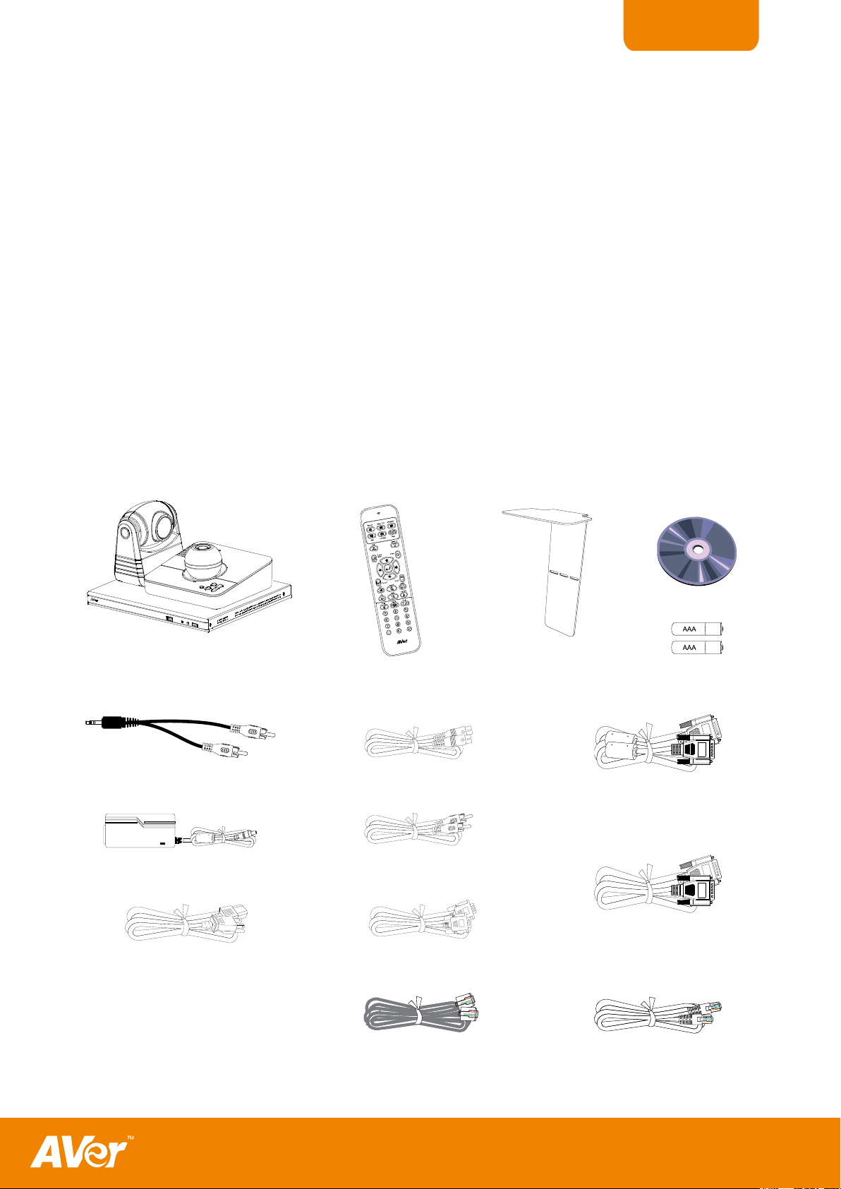
PPaacckkaaggee CCoonntteennttss
AVer™ H300/H100
(main system, camera, table
hub and mic)
Remote Control
L-Bracket
(camera stand)
Manual CD
2 AAA Batteries
Phone to RCA Cable
Power Adapter
Power Cord
* The power cord will vary
depending on the standard
power outlet of the country
where it is sold.
S-Video Cable
RCA Cable
VGA Cable
6P4C Cable
26Pin-DSub Cable
(female/female)
26Pin-DSub Cable
(male/male)
RJ-45 Cable
Thank you for choosing AVer H300/H100. H300/H100 is a video conferencing device which
allows you to see and communicate with your client. With H300, you can create a 4-party video
conference call with your board members from different countries or locations. This saves you
time and travel expenses.
H300/H100 uses 5-megapixel camera sensor and gives you high definition 720p video quality.
H300/H100 Table Hub comes with a built-in speaker. You can hook up the 2nd display device in
the Table Hub like an LCD projector for a bigger screen or with a dual screen setup which
allows you to have your presentation and video conference shown simultaneously. By using a
USB flash drive, you can record the meeting and review it anytime on H300/H100 or on PC with
the bundled AVer VC player and share it with your meeting attendees.
Make sure the following items are included in the package.
1
Page 6
ENGLISH
GGeett FFaammiilliiaarr wwiitthh tthhee HH330000//HH110000
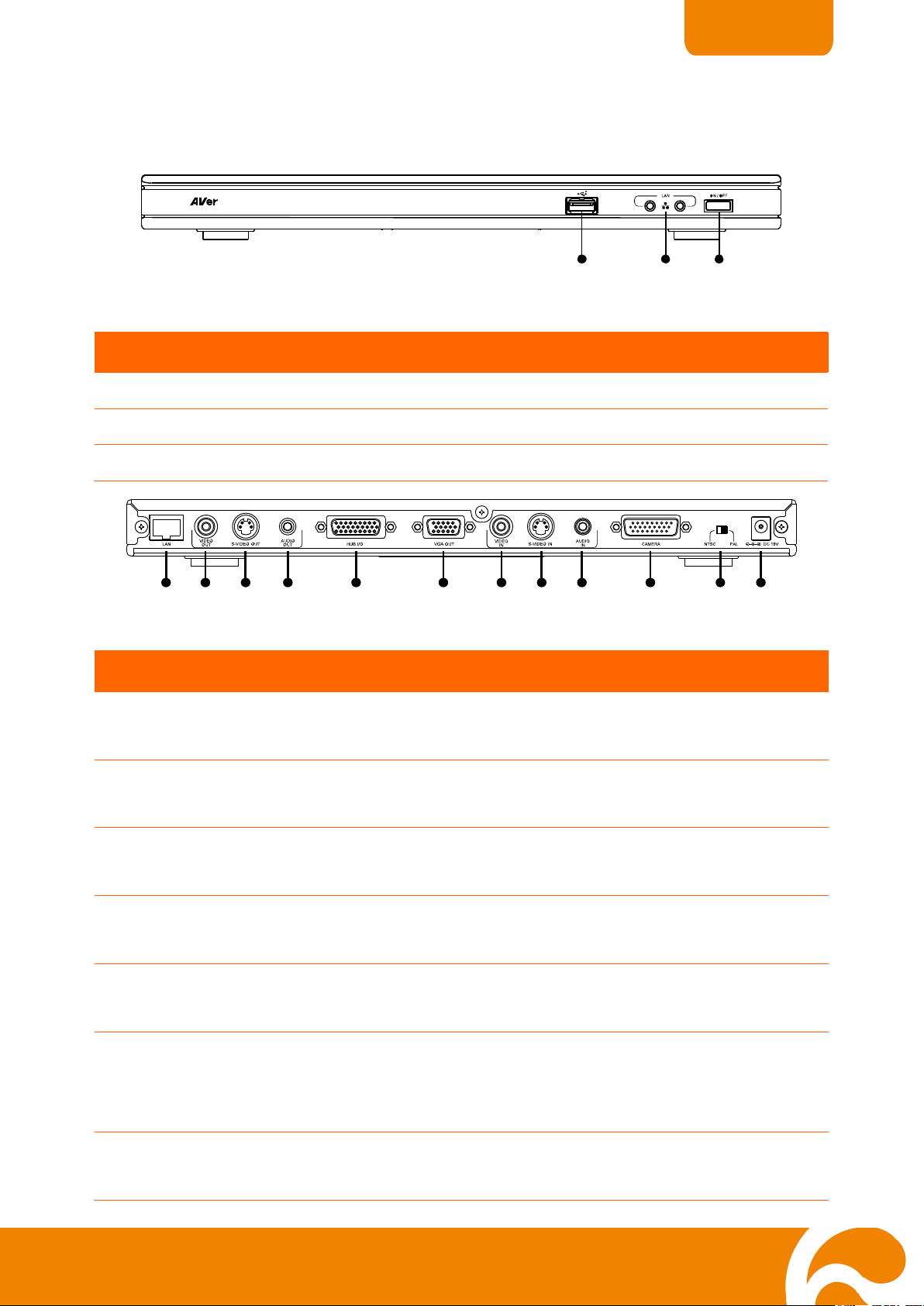
(1) (2) (3)
Name
Function
(1) USB Flash Drive port
Insert a USB flash drive for recording the meeting.
(2) Network Status
Check the network connection.
(3) Power
Turn on/off the main system.
(1) (2) (3) (4) (5) (6) (7) (8) (9) (10) (11) (12)
Name
Function
(1) LAN
Use an RJ-45 Ethernet cable and connect it to RJ-45 Ethernet
port. Make sure to connect H300/H100 to an IP-based network.
(2) VIDEO OUT
Output the video signal from the main system on an TV thru RCA
video connection.
(3) S-VIDEO OUT
Output the video signal from the main system on an TV thru SVideo connection.
(4) AUDIO OUT
Output the audio signal from the main system on an TV thru
RCA left and right audio connection.
(5) HUB I/O
Send and receive signal between the main system and table
hub.
(6) VGA OUT
Output the video signal from the main system on a flat panel
monitor/LCD TV or LCD/DLP projector thru RGB connection.
In dual monitor mode, this will be the main screen.
(7) VIDEO IN
Receive the video signal from a media device thru RCA video
connection.
Main System
Main system front panel (fig. 1.1)
Main system back panel (fig. 1.2)
2
Page 7
ENGLISH
Name
Function
(8) S-VIDEO IN
Receive the video signal from a media device thru S-Video
connection.
(9) AUDIO IN
Receive the audio signal from the audio device thru RCA left and
right audio connection.
(10) CAMERA
Receive the image from the camera to the main system.
(11) NTSC/PAL
Set the correct TV display output system.
(12) DC 19V
Connect the power adapter into this port.
AV e rM e d i a IN F O R M A TIO N, In c .
Atte n tio n:
DO NO T O PEN THE CASE
Warranty voi difthecasehas been opened.
AVerComm H Series(Hub)
ModelNo.: V2D1
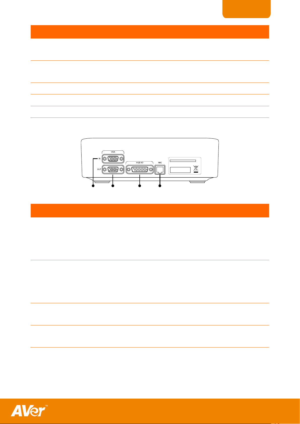
(1 ) (2 ) (3 ) (4 )
Name
Function
(1) VGA IN
Input the signal from a computer or other sources. Connect this
port to the VGA output port of a computer. Press PRESENT on
the remote and select VGA IN to share and display the computer
image with the video conferencing camera image.
(2) VGA OUT
Output the video signal from the main system on a flat panel
monitor or LCD/DLP projector thru VGA connection. In dual
monitor mode, this port will display the local screen or present
screen when the content is being shared.
(3) HUB I/O
Send and receive signal between the main system and Table
Hub.
(4) MIC port
Receive the audio signal from the MIC to main system. Use the
6P4C cable to connect the mic and Table Hub.
Table Hub
Table Hub back panel (fig. 1.2)
3
Page 8
ENGLISH
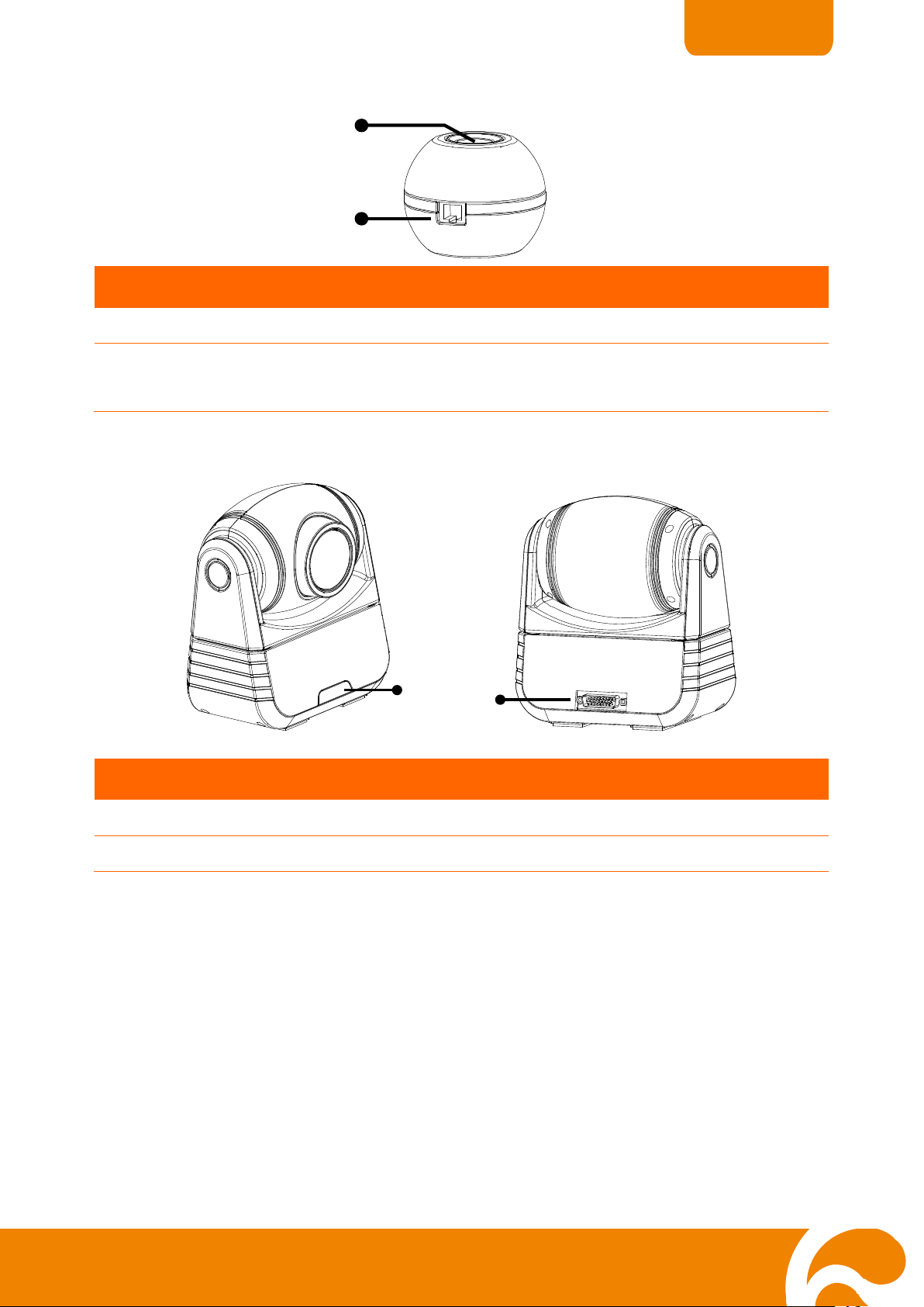
(2)
(1)
Name
Function
(1) Mute
Turn on/off the mic.
(2) MIC port
Use the 6P4C cable and connect the other end to the
Table Hub MIC IN port.
(1)
(2)
Name
Function
(1) IR Sensor
Aim the remote control here to operate the unit.
(2) CAMERA
Send the signal from the camera to the main system.
MIC
Camera
(fig. 1.3)
(fig. 1.4)
4
Page 9
ENGLISH
* Available in H300 model only.
Name
Function
(4)
(8)
(3)
(5)
(23)
(22)
(12)
(10)
(17)
(16)
(2)
(1)
(18)
(19)
(20)
(14)
(6)
(7)
(9)
(15)
(13)
(11)
(21)
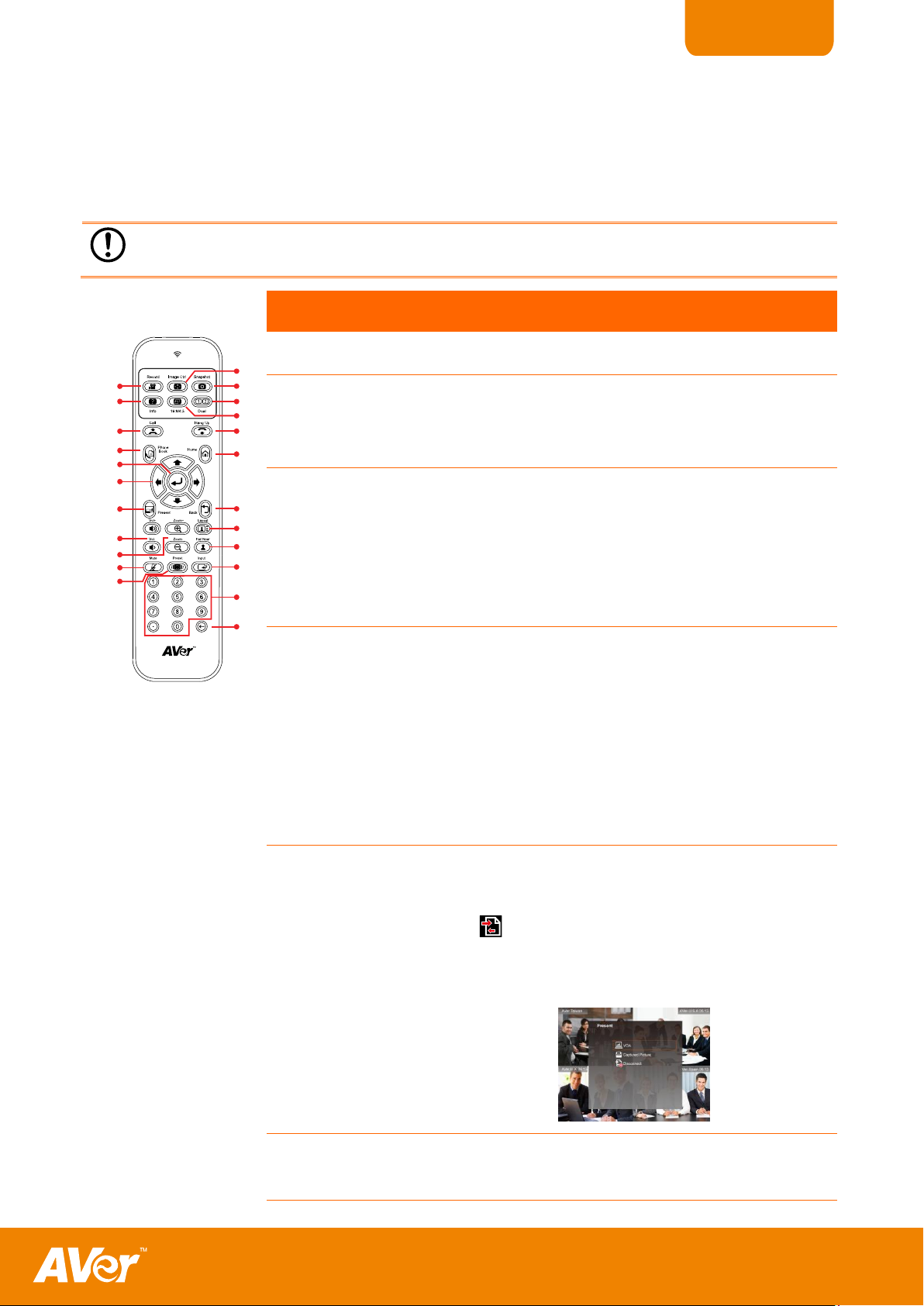
(fig. 1.5)
(1) Call
Start a call or add another party.
(2) Phone Book
Search contact to make a call.
Enter to add, edit, delete or create group
contact entry.
(3) Enter
Make a selection in OSD menus or on-screen
keyboard.
Accept incoming call.
Display the site name and icon during the
meeting.
(4) ▲,▼,◄, &
►
Use these buttons to navigate through the
selections in OSD menus or on-screen
keyboard.
Pan and tilt the camera to adjust the visual
angle of the camera.
Pan, tilt the zoomed in camera image or the
captured image.
(5) Present
Share either the video/image from the VGA IN
port or the captured image.
This present icon will appear on the screen
to indicate sharing the present image. The
present icon will disappear in 5 sec.
(6) Vol +/-
Increase/decrease the speaker volume.
Remote Control
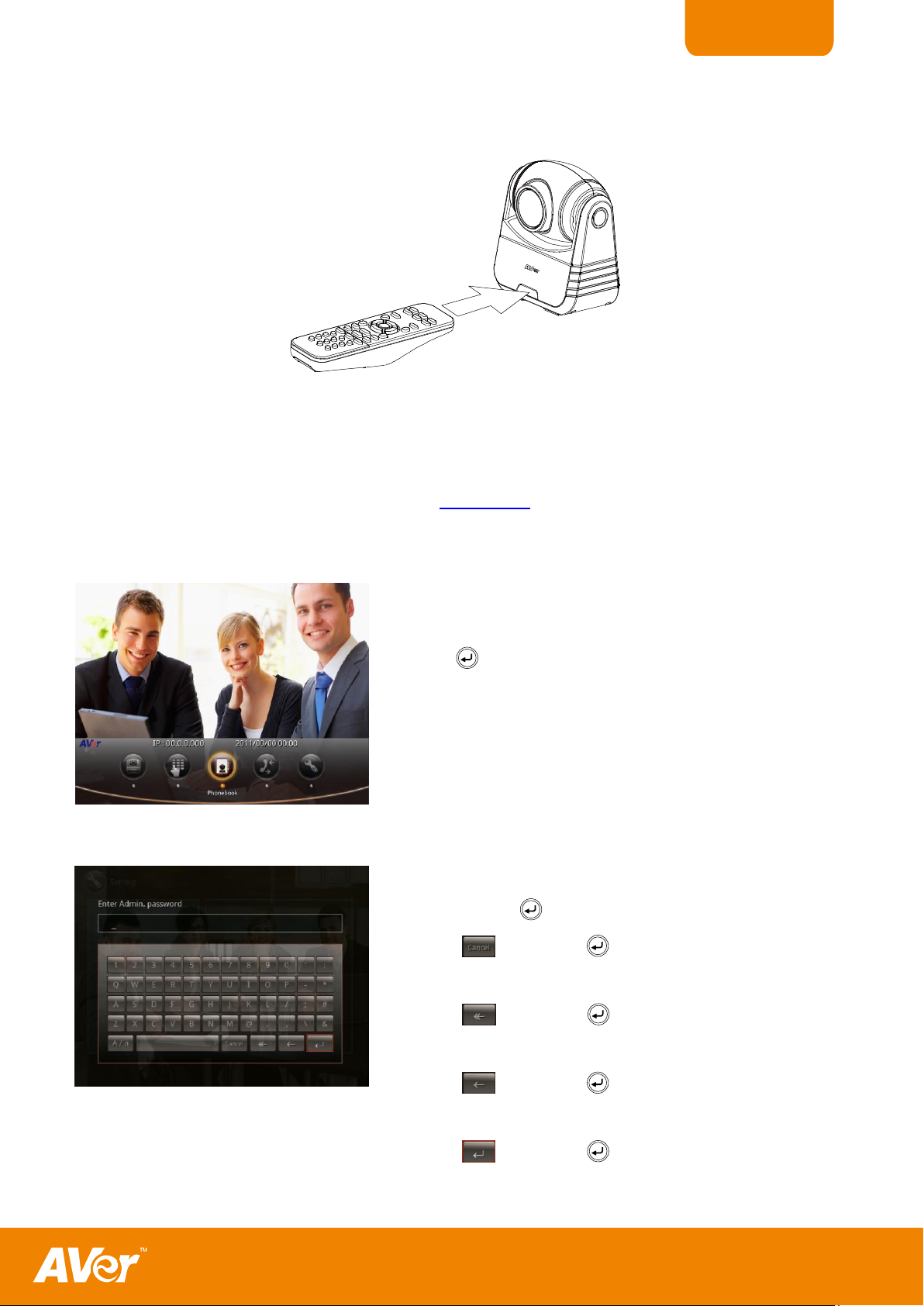
The remote control requires two (2) “AAA” size batteries (supplied), make sure batteries are
installed properly before using. Aim the remote control to the H300/H100 camera infrared
sensor to operate the unit.
5
Page 10
ENGLISH
Name
Function
(4)
(8)
(3)
(5)
(23)
(22)
(12)
(10)
(17)
(16)
(2)
(1)
(18)
(19)
(20)
(14)
(6)
(7)
(9)
(15)
(13)
(11)
(21)
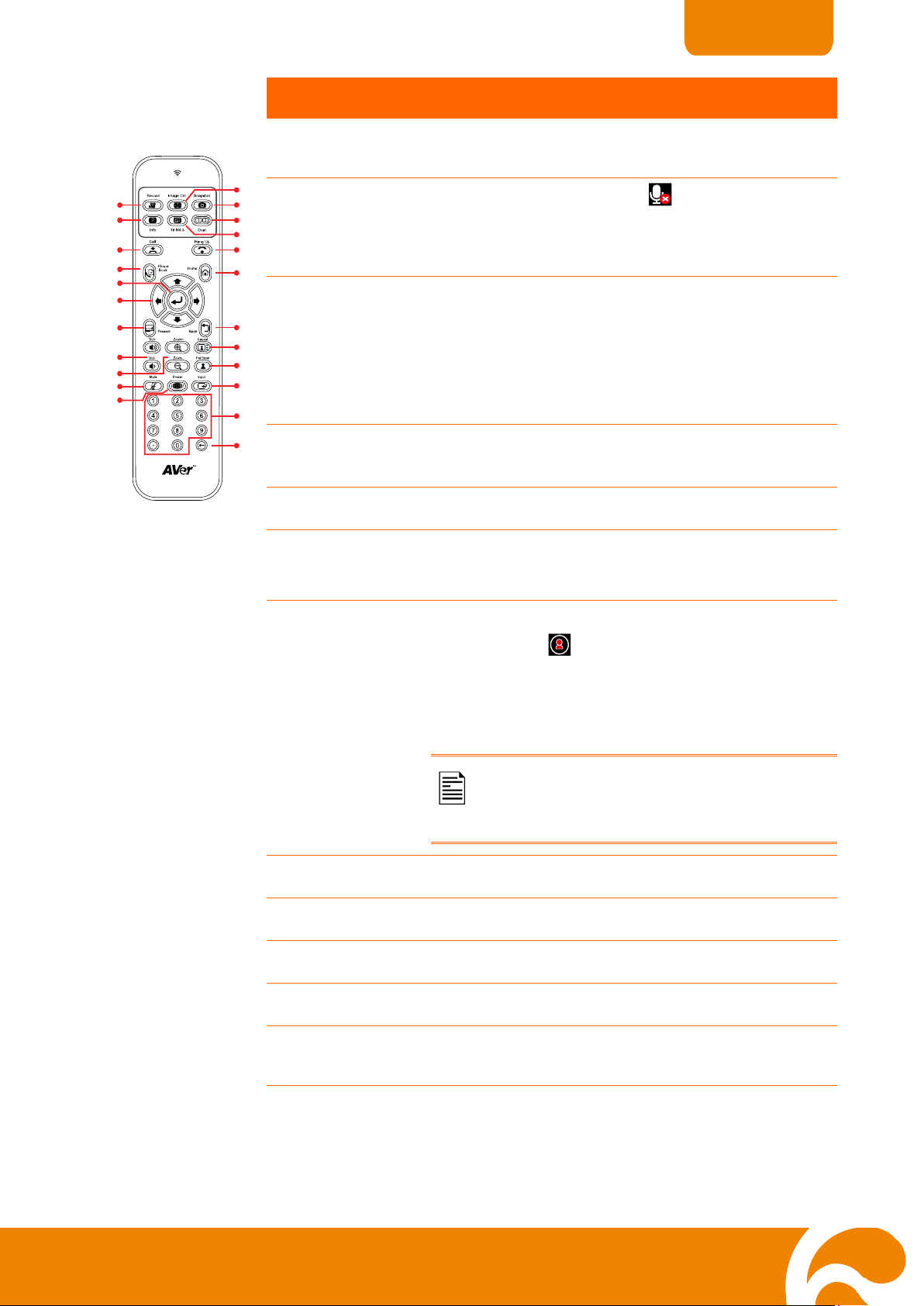
(7) Zoom +/-
Increase/decrease the camera image or the
captured image magnification.
(8) Mute
Turn on/off the MIC. This mute icon will
appear when the mic is turned off. The mute
icon will become translucent in 5 sec.
(9) Preset
Press hold for 3 sec to set the position of the
camera preset point from the selected
number. The preset point can be set from 0-9.
Press to move the camera target to the
selected preset point number.
(10) Backspace
Move back one space and delete one
character at a time.
(11) Numeric Pad
Use to enter numeric number.
(12) Input
Switch the input source between H300/H100
camera, S-Video, or Video.
(13) Far/Near
Select to control either near site or far site
camera. The cam ctrl icon will appear on
the screen to show which camera site you are
going to control. The cam ctrl icon will
disappear in 5 sec.
The camera from the far site can only
be operated when the enable far site to
control the camera is permitted.
(14) Layout
Change to different split screen mode.
(15) Back
Return to previous OSD menu selection.
(16) Home
Call up the main screen.
(17) Hang Up
End the call.
(18) 16:9/4:3
Toggle between 16:9 or 4:3 to match the
monitor aspect ratio.
6
Page 11
ENGLISH
Name
Function
(4)
(8)
(3)
(5)
(23)
(22)
(12)
(10)
(17)
(16)
(2)
(1)
(18)
(19)
(20)
(14)
(6)
(7)
(9)
(15)
(13)
(11)
(21)
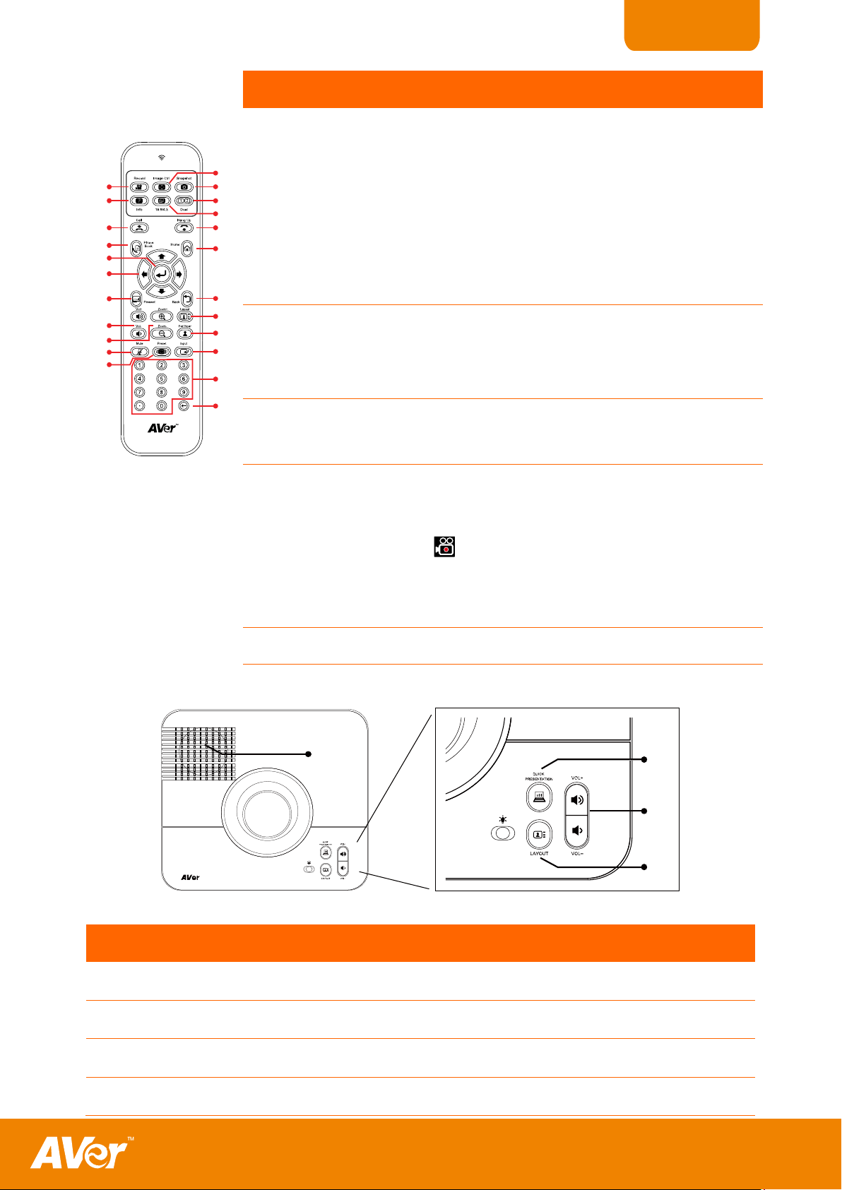
(19) Dual
Switch to Dual monitor mode. This split the
video conference screen and present screen.
The video conference screen will be displayed
on the monitor connected to the VGA OUT of
the main system and the present screen will be
displayed on the monitor connected to the VGA
OUT of the table hub.
(20) *Snapshot
Capture the image from the camera.
You can share the captured image using the
Present function. See (5) Present.
(21) *Image Ctrl
Zoom and pan, tilt the displayed captured
image in the shared screen.
(22) *Record
Start/Stop meeting recording. The recording
can only be saved in a USB storage drive.
The record icon will appear on the screen to
show which site is recording. The record icon
will become translucent in 5 sec.
(23) Info
Display the call statistics information.
(4)
(2)
(1)
(3)
Name
Function
(1) QUICK PRESENTATION
Share the data from VGA IN.
(2) VOL +/-
Increase/decrease the speaker volume.
(3) LAYOUT
Change to different split screen mode.
(4) SPEAKER
Location of the speaker.
Table Hub Control Panel
Table Hub control panel (fig. 1.6)
7
Page 12
ENGLISH
MMaakkiinngg tthhee CCoonnnneeccttiioonnss
Make sure to connect all the connection before connecting the power.
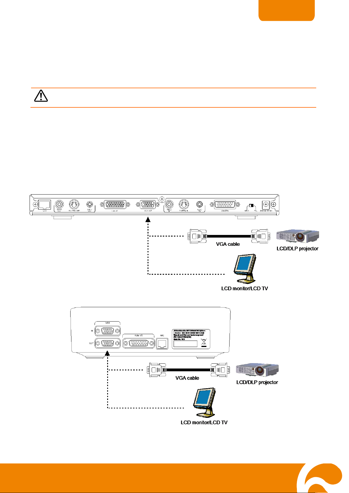
CCoonnnneeccttiinngg aa VVGGAA ddiissppllaayy ddeevviiccee oouuttppuutt
Before making the connection, make sure the power of all devices are turned off. If you are not
sure on where to connect, simply follow the illustrated connections below and also refer to the
user manual of the device you are connecting the H300/H100 with.
Locate the VGA input port of the graphics display device and connect it to VGA OUT 1 (main
system) or VGA OUT 2 (Table Hub) port of H300/H100. Both VGA OUT 1 and 2 can be used at
the same time. For sharing data from VGA IN or the captured image in PRESENT mode, the
present screen will be displayed in VGA OUT 2 when you split the video conference screen and
present screen in DUAL mode.
8
Page 13
ENGLISH
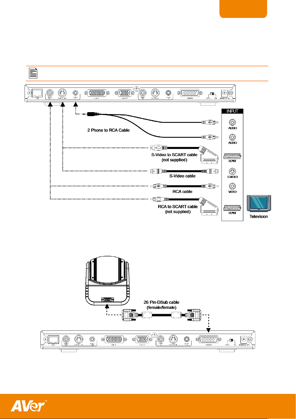
CCoonnnneeccttiinngg aa TTVV ddiissppllaayy oouuttppuutt
Make sure NTSC/PAL switch setting is set to proper TV system.
CCoonnnneeccttiinngg tthhee ccaammeerraa ttoo mmaaiinn ssyysstteemm
Locate the S-VIDEO, VIDEO or SCART RGB of the TV/LCD monitor and connect it to
H300/H100.
Locate the CAMERA port of the camera and connect it to the CAMERA port of the main system.
9
Page 14
ENGLISH
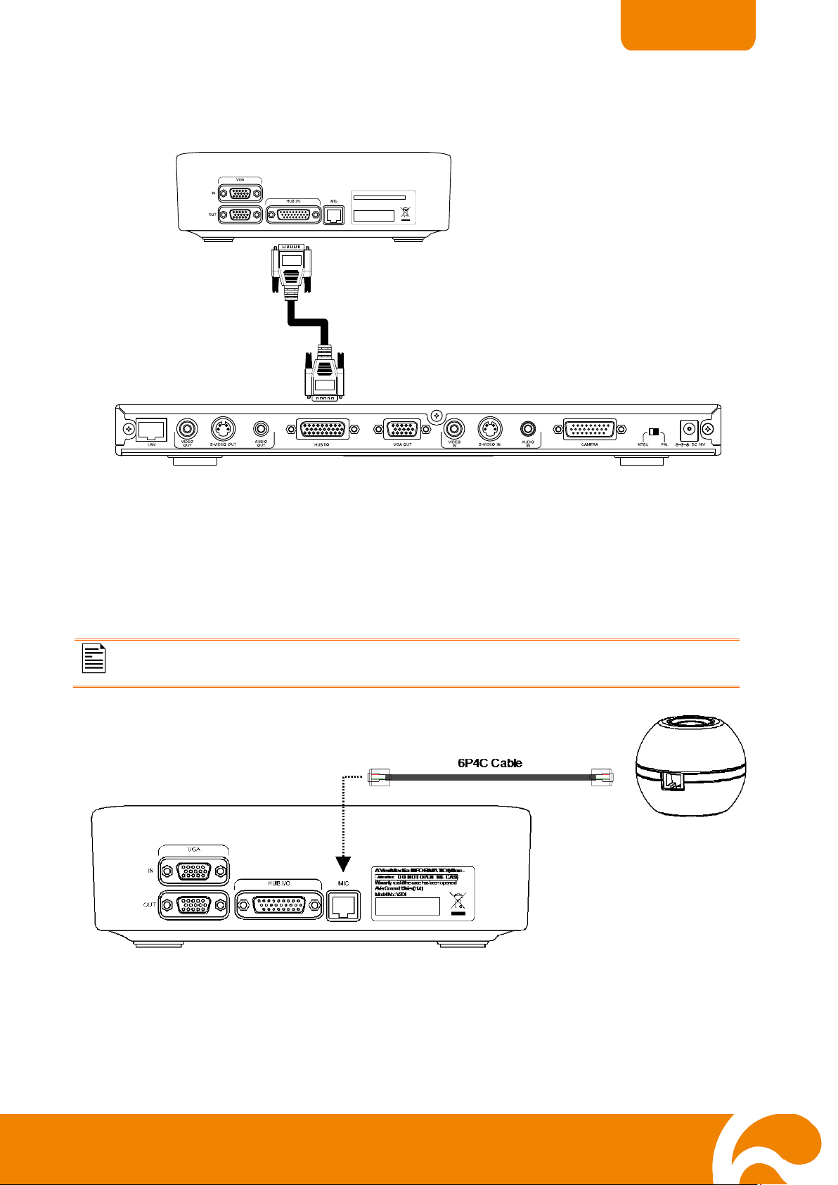
CCoonnnneeccttiinngg tthhee TTaabbllee HHuubb aanndd MMaaiinn SSyysstteemm
26 Pin D-Sub cable
(male/male)
AV e rM e d ia INFO R M A TIO N, In c .
Atten tion :
DO NOT O PEN THE CASE
Warranty void if the case has been opened.
AVer Comm H Series (Hub)
Model No.: V2D1
CCoonnnneeccttiinngg tthhee MMIICC
Press the button on top of H300/H100 Mic to turn on/off the mic.
Locate the HUB I/O port of the table hub and connect it to HUB I/O port of the main system.
Locate the MIC port of the table hub and use the supplied 6P4C cable then connect it to Mic
port.
10
Page 15
ENGLISH
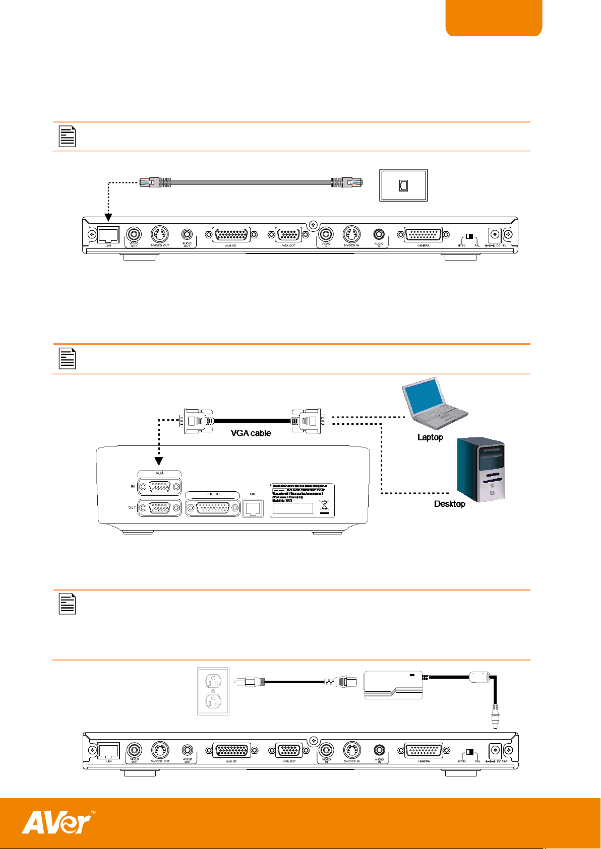
CCoonnnneeccttiinngg tthhee LLAANN
Make sure to connect it to an IP-based network.
RJ-45 cable
RJ-45 wall jack
CCoonnnneeccttiinngg aa CCoommppuutteerr
To share the data, press PRESENT and select “VGA”.
CCoonnnneeccttiinngg tthhee PPoowweerr
To prevent shock, make sure the connection ports in the main system are
connected before connecting the power and turning on the power.
Make sure to use the supplied 19V power adapter.
Power adapter
Power cord
Wall outlet
Use an RJ-45 Ethernet cable and connect it from the LAN port of H300/H100 to RJ-45 wall jack
or Ethernet hub.
Locate the VGA output port of the computer or laptop and connect it to VGA IN port of
H300/H100 Table Hub.
Connect the power adapter to a standard 100V~240V AC power outlet.
11
Page 16
ENGLISH
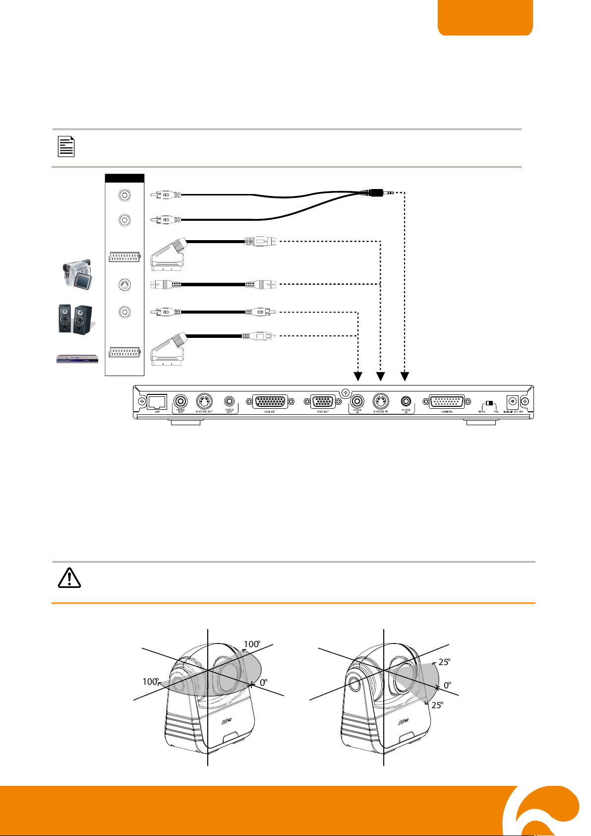
CCoonnnneeccttiinngg aa DDVVDD ppllaayyeerr oorr CCaammccoorrddeerr
Make sure NTSC/PAL switch setting is set to proper TV system.
For better video quality, we strongly suggest using S-Video Connection.
S-VIDEO
VIDEO
SCART
SCART
OUTPUT
DVD
AUDIO
AUDIO
Speaker
S-Video to SCART cable
(not supplied)
S-Video cable
RCA cable
RCA to SCART cable
(not supplied)
2 Phone to RCA Cable
Camcorder
SSeettttiinngg UUpp HH330000//HH110000
Avoid manually adjusting the camera to prevent misalignment and damaging the
pan and tilt motor. Always use the remote control to pan and tilt the camera head.
Locate the S-VIDEO, VIDEO and AUDIO output port of the media player (i.e., DVD player) or
camcorder to share the video instead of the image from the camera and connect it to S-VIDEO
IN, or VIDEO IN and Audio IN port of H300/H100.
This section provides useful tips on how to setup the H300/H100 to meet your needs.
Camera
The H300/H100 camera design can be panned (Ø +- 100 deg range), tilted (Ø +- 25 deg range)
and zoomed (7X) with the use of the ▲, ▼, ◄ and ►, and Zoom +/- buttons on the remote
control.
12
Page 17
ENGLISH
RRuunnnniinngg tthhee HH330000//HH110000
1. In the Home menu, press ► and ◄ on the remote to
toggle between the 5 selections.
2. Press to make a selection or the new setting to
take effect.
1. Use the ▲, ▼, ◄ and ► buttons to move the
selection and to make a selection.
2. Select and press to void the action and
return to the previous or Home menu.
3. Select and press to delete all the entered
characters or number.
4. Select and press to delete one character
or number.
5. Select and press to save and take effect
the action and return to previous menu.
Infrared Sensor
Aim the remote control at the camera infrared sensor to operate the unit.
Upon running the H300/H100 for the first time or the system is being reset, the system will
instantly direct you to Quick Start menu. See Quick Start.
Navigating the Menus and Settings
Using the On-screen keyboard and numeric pad
13
Page 18
ENGLISH
6. For numeric pad, you may use the number button on
the remote and press to save and take effect
the action and return to previous menu. Before
you press , make sure in the numeric pad the
is selected.
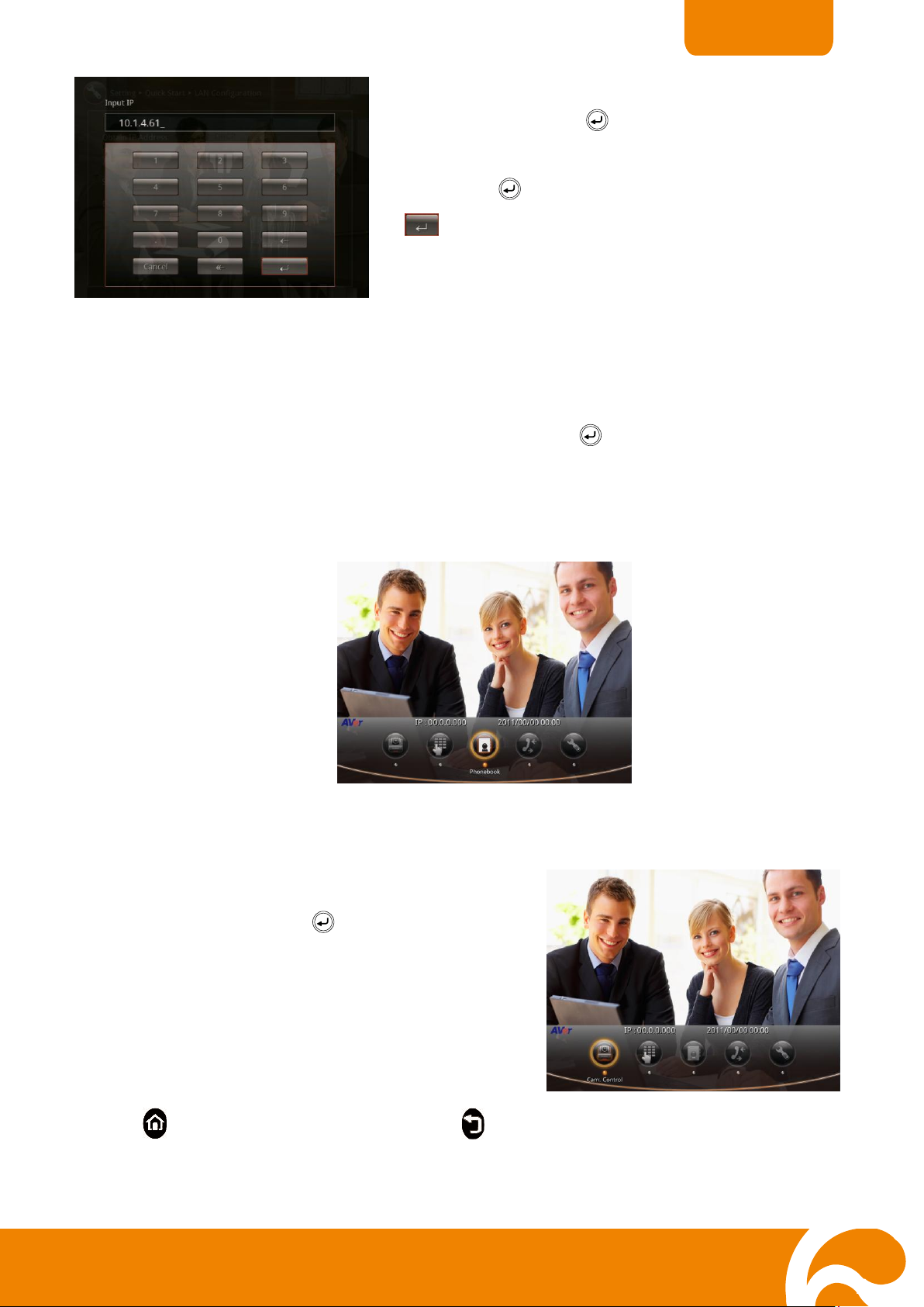
HHoommee MMeennuu SSccrreeeenn
To Adjust the H300/H100 Camera
1. Select Cam Ctrl and press . The screen will
completely show the camera image and hide the
Home menu.
2. Using the remote control, press ◄ and ► to pan, ▲
and ▼ to tilt, and Zoom+ and Zoom- to increase and
decrease the camera magnification.
3. Press to call up the Home menu again or to
return to previous.
There are 5 selections on the Home menu screen: Cam Ctrl, Dial, Phonebook, Call History, and
Setting. Upon running the H300/H100, the Home menu screen will be displayed. Simply use
the ► and ◄ buttons to move between selections and press to make a selection. You can
easily place a call and select the site contact either in Phonebook, Call History, or Dial. The
administrator can also set security password to prevent changing the system setting and
WebTool access.
Cam Ctrl
The Cam Ctrl allows you to adjust the visual angle of the camera, before making a call.
14
Page 19
ENGLISH
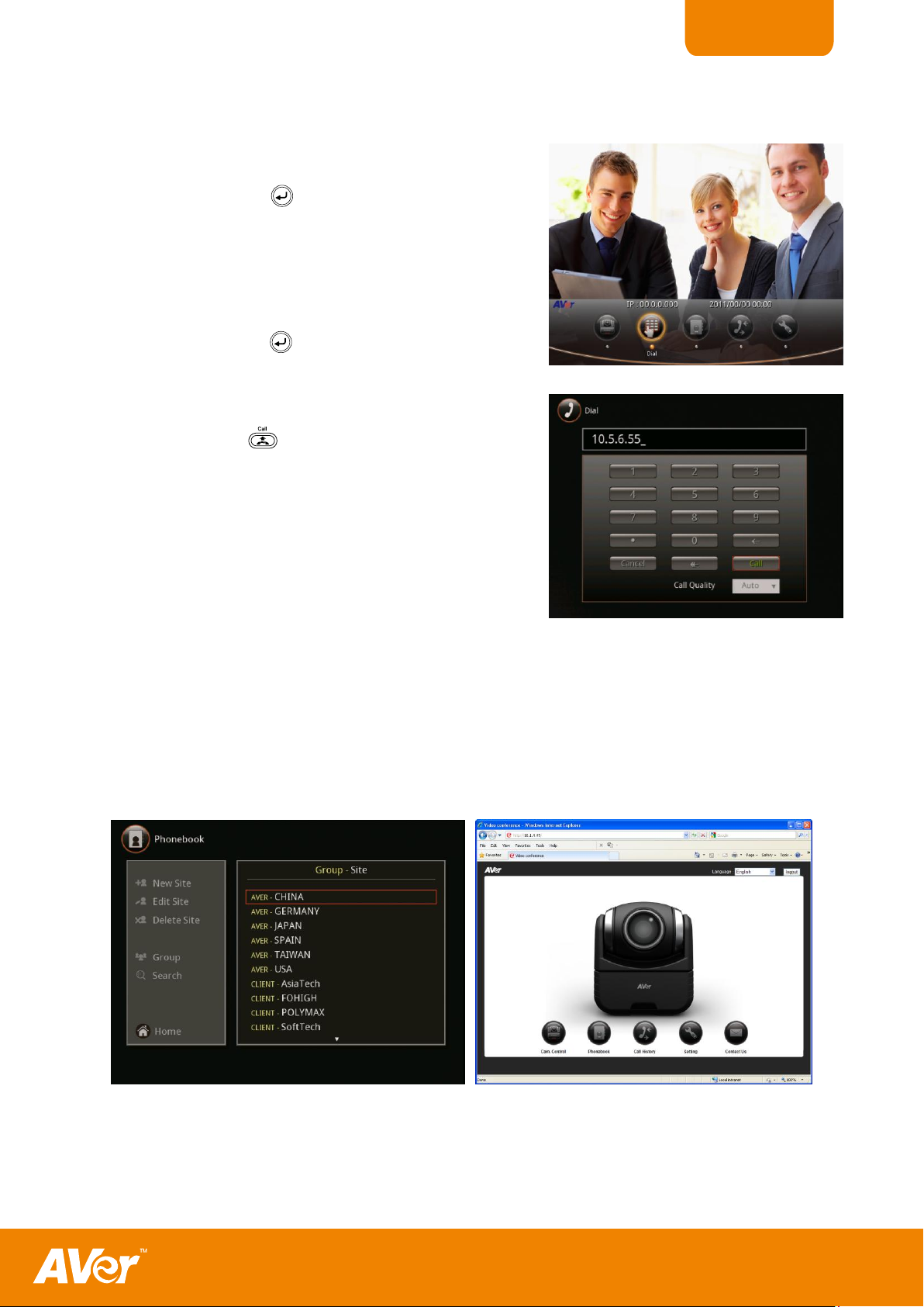
To Make a Call Using Dial
1. Select Dial and press . The on-screen numeric
pad will appear.
To set the Call Quality, use ▲, ▼, ◄ and ► buttons
to move the selection box to the Call Quality drop-
down list and press to select the value.
2. Use the numeric button on the remote to enter the IP
address and press to make a call.
Dial
The Dial allows you to make a call by entering the IP address and set the call quality setting.
Phonebook
The Phonebook allows you store, edit, delete contact information, group contact by category,
search contact and make a call. The group and site name of the contacts in the directory will be
displayed in alphabetical order. You may also use the WebTool to work on the phonebook
entries.
15
Page 20
ENGLISH
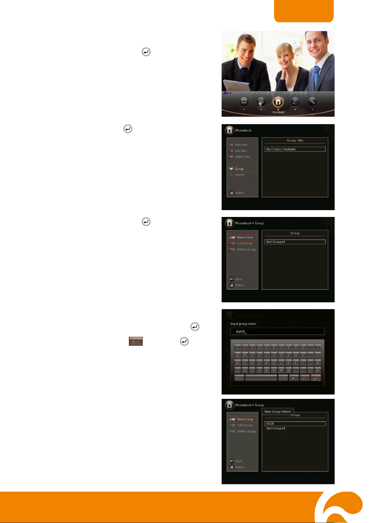
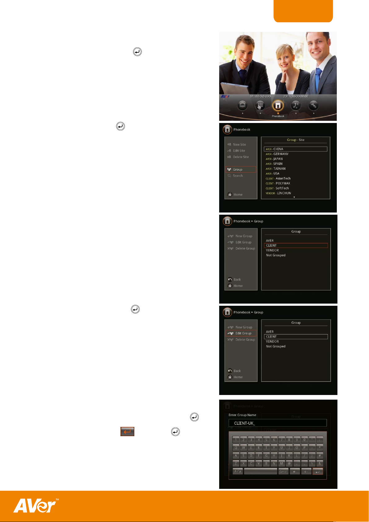
To Add Group
1. Select Phonebook and press .
2. Select Group and press .
In grouping the contacts, you can easily
categorize the contacts into a specific group such
as client, vendor, company, branch, and etc.
3. Select New Group and press .
4. Use the ▲, ▼, ◄ and ► buttons to move the
selection in the on-screen keyboard and press to
make a selection. Select and press to
save the new group name.
5. The new group name will be saved and displayed in
the Group list.
16
Page 21
ENGLISH
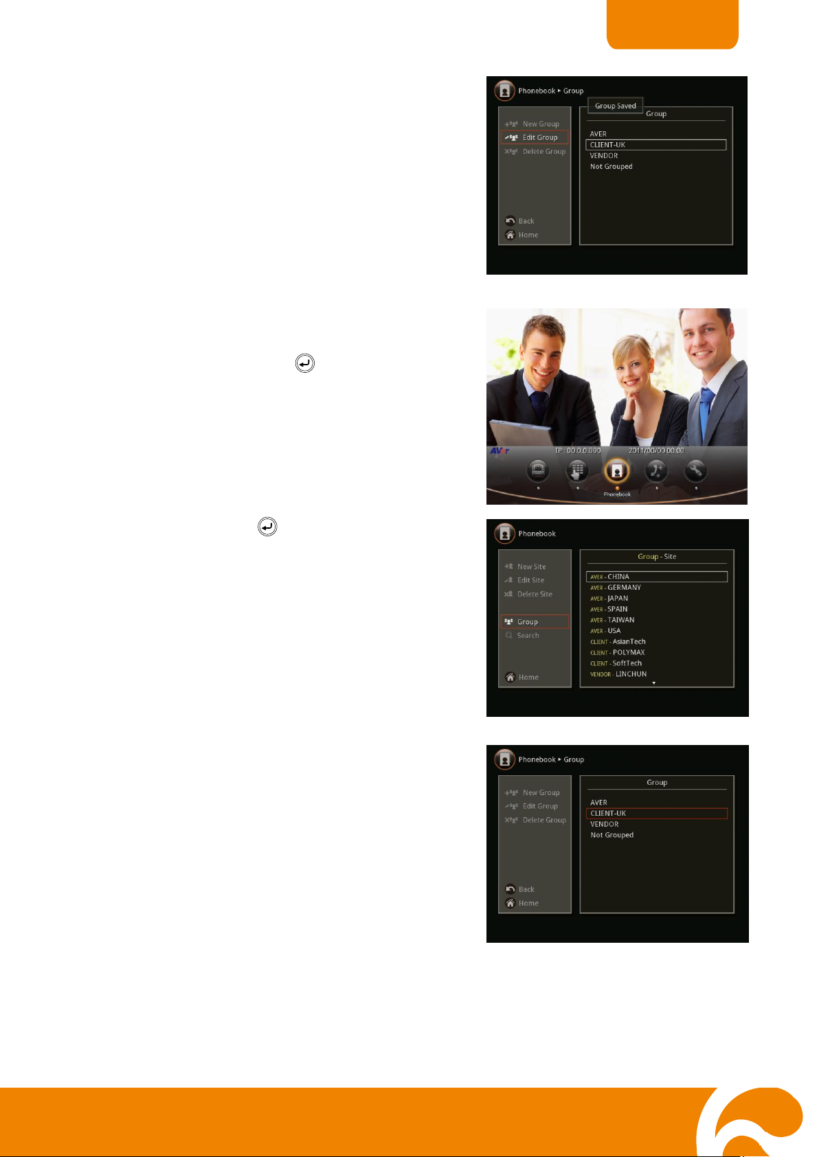
To Edit Group
1. Select Phonebook and press .
2. Select Group and press .
3. Select the name you want to modify in the Group list.
4. Select Edit Group and press .
5. Use the ▲, ▼, ◄ and ► buttons to move the
selection in the on-screen keyboard and press to
make a selection. Select and press to save
the revised group name.
17
Page 22
ENGLISH
6. The revised group name will be saved and displayed
in the Group list.
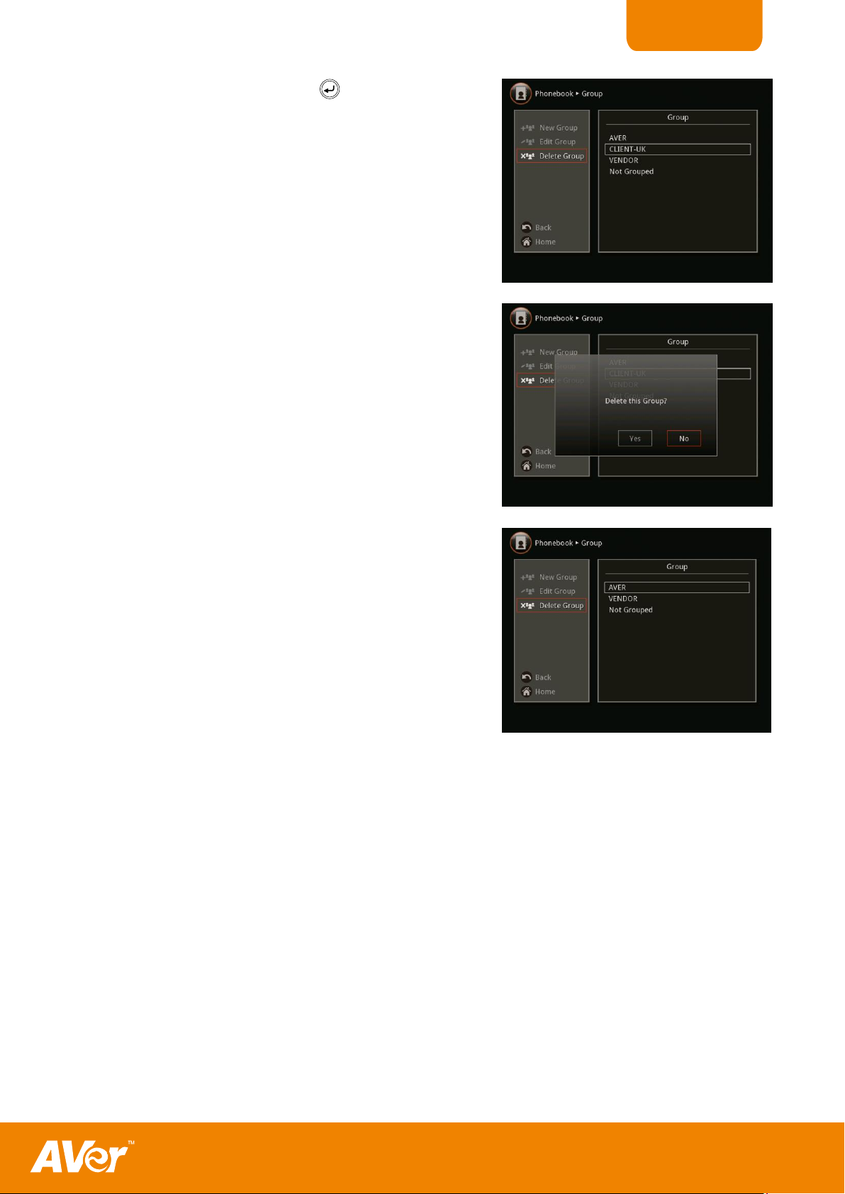
To Delete Group
1. Select Phonebook and press .
2. Select Group and press .
3. Select the name you want to remove in the Group list.
18
Page 23
ENGLISH
4. Select Delete Group and press .
5. Select “Yes” to remove the selected group name and
“No” to cancel group name deletion.
6. The selected group name will no longer appear in the
group list when deleted.
19
Page 24
ENGLISH
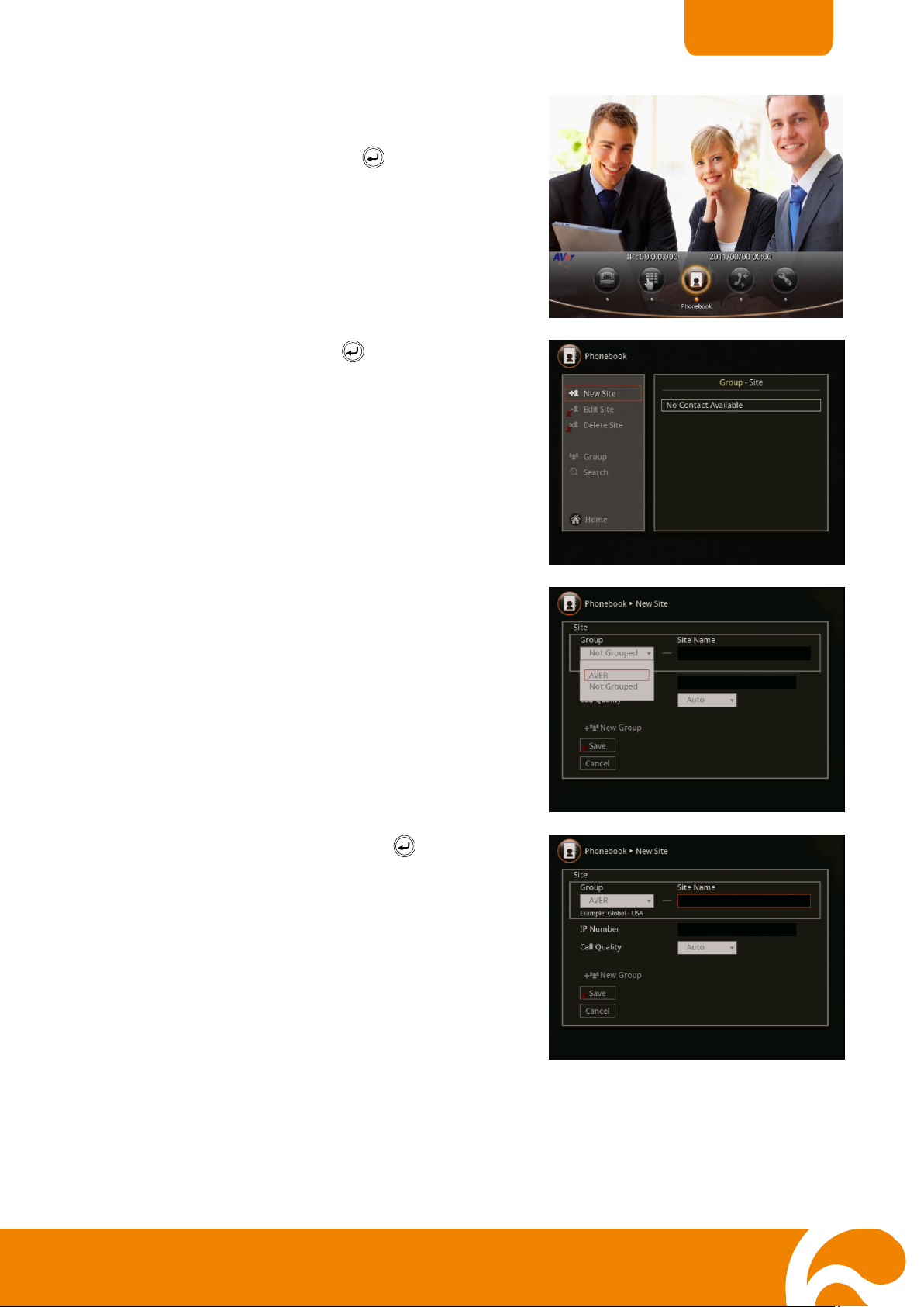
To Add Phonebook Entries
1. Select Phonebook and press .
2. Select New Site and press .
3. Select the group name.
4. Select Site Name box and press .
20
Page 25

ENGLISH
5. Use the ▲, ▼, ◄ and ► buttons to move the
selection in the on-screen keyboard and press to
make a selection. Select and press when
you are done to save the new site name.
6. Select the IP address box and press .
7. Use the numeric number button on the remote
to enter the IP address and select to save.
8. Select the call quality value in the drop-down
box and press .
The bandwidth setting in the Auto Call Quality
selection will be used when Auto is selected in
Call Quality.
21
Page 26

ENGLISH
9. Select Save to store the newly added site
contact and Cancel to undo adding contact.
To Edit Phonebook Entries
1. Select Phonebook and press .
2. Select the contact you want to modify.
3. Select Edit Site and press .
22
Page 27

ENGLISH
4. In the Phonebook > Edit Site, you may change
the Group name, Site Name, IP Address, and
Call Quality.
5. After making the changes, select Save to apply
the new changes or Cancel to undo the changes
and return to Phonebook menu.
6. The saved changes will be shown in the GroupSite list.
To Delete Phonebook Entries
1. Select Phonebook and press .
2. Select the contact you want to delete.
23
Page 28

ENGLISH
3. Select Delete Site and press .
4. Select “Yes” to remove the selected contact and “No”
to cancel contact deletion.
5. The selected contact will no longer appear in the
group-site list when deleted.
To Check the IN/OUT Calls
1. Select Call History and press .
Call History
The Call History allows you to check the incoming and outgoing calls and to make a call by
selecting in the Call History list. You may also find if the call is being answered or failed
connection.
24
Page 29

ENGLISH
2. In the Call History, it will show the IP address or
the Site name, Date and Time of call and Call
status. Refer to the table below to check the call
status.
Call Status
Answered
Failed
IN
OUT
To Make a Call in Call History
1. Select Call History and press .
2. Use the ▲, and ▼ buttons to move the selection
and scroll up and down in the call history list and
press to make a call.
3. The call will be connected.
25
Page 30

ENGLISH
Enable/ Disable Administrator Setting
1. Select Setting and press .
2. Select Administrator and press .
3. Select Enable Admin and press to
enable/disable authorizing to change the system
setting, Enable Web Admin to enable/disable
using the WebTool to access the unit, and
Enable Remote to enable/disable using
application programming interface to control the
unit.
Setting
In the Setting menu, allows you to modify system setting, check the system info, test the
system before using H300/H100 and watch the recorded file.
Administrator
The Administrator allows you to set password to prevent unauthorized user to change the
system settings, access WebTool, and allow using application programming interface to
remotely communicate with the unit. To avail the source codes, go to our website and contact
our technical support.
26
Page 31

ENGLISH
4. If you activate all Enable Admin, Enable Web
Admin and Enable Remote or any of the 3
selections, you need to change the password.
Select Change Password and press . Then
enter the default password or the last used
password.
Note: The default password is 1234.
5. Use the ▲, ▼, ◄ and ► buttons to move the
selection in the on-screen keyboard and press to
make a selection. Select and press when
you are done entering the password.
6. You will be asked to enter the password again
for confirmation.
7. The entered password will be saved. Press to
go back to previous menu.
27
Page 32

ENGLISH
To Setup the H300/H100
1. In the Home menu, click Setting and select
System Settings > Quick Start.
If the system is administrator password
protected, you need to enter the password to
change the System Settings.
2. In the Quick Start menu, you can modify following
settings:
Language
System Name
LAN Configuration
Network
Date and Time
Quick
The Quick Start is the easiest way for you to set up the system if you are using H300/H100 for
the first time.
Start
28
Page 33

ENGLISH
To Setup the Language
1. Select Language and press .
2. Use the ▲ and ▼buttons and select from the
language you prefer.
3. Press to change the system into the selected
language.
To Setup the System Name
1. Select System Name and press .
2. Use the ▲, ▼, ◄ and ► buttons to navigate and
to make a selection.
3. Select and press to save and take effect
the action and return to previous menu.
The system name will be displayed on the
screen for 5 sec after making a call or answered
a call.
29
Page 34

ENGLISH
LAN configuration
1. Select LAN Configuration and press .
2. In Obtain IP Address selection, select the type
of IP and press .
DHCP – configures the system to
automatically obtain IP address from the
DHCP server.
Static IP – configures the system to use the
assigned IP Address. Select this when the
public IP address is available.
Your IP address is - shows the current IP
address; enter info when you need to
configure your IP address manually.
Subnet Mask - shows the designated IP
address routing prefix; enter info when the
system does not automatically obtain the
subnet mask.
Default Gateway - allows traffic from one
point and exit point in network; enter info
when the system does not automatically
obtain the gateway.
3. Select Apply and press to save the setting.
30
Page 35

ENGLISH
To Setup the Network
1. Select Network and press .
You may also set the network setting in Network
selection. Go to Setting > System Settings >
Network.
2. Select the maximum transmitting and receiving
bandwidth and press to make a selection.
Max. Transmitting/Receiving Bandwidth -
allows you to specify the maximum bandwidth
of the outbound and inbound calls.
H300/H100 system supports up to 4Mb.
Auto Call Quality - enables you to select
default outbound/inbound bandwidth. This setting
will be used when Auto is selected in the Call
Quality setting.
To Setup the Date and Time
1. Select Date and Time and press .
2. Select the Date and Time format you prefer and
enter the date and time value.
31
Page 36

ENGLISH
To Enable/Disable Far Control of Near Camera:
1. Select Setting and press .
2. Select System Settings.
3. Select General Setting
General Setting
In General Setting, you can enable/disable Far Control of Near Camera to allow the far site to
control your Camera, select the system language, set the monitor aspect ratio, enable/disable
Auto Power-off mode to switch in standby mode when not in use for 2 hours, set the system to
automatically answer/reject the incoming call, and setup the system date and time.
32
Page 37

ENGLISH
4. Select Far Control of Near Camera. Enable to
let the far site control your camera.
To Set the Monitor Aspect Ratio
1. Select Setting and press .
2. Select General Setting > General Setting and
press .
3. Select Monitor Aspect Ratio drop-down box and
press . Choose the appropriate aspect ratio
of the display device you using. If you want the
system to automatically detect the right setting,
choose Auto. Press to make the selection.
33
Page 38

ENGLISH
To Set the Screen Saver Timer
1. Select Setting and press .
2. Select System Settings > General Setting and
press .
3. Select Screen Saver drop-down box and press
. Then select the time for the system to
automatically switch to standby mode or OFF to
disable this feature. Press to make a
selection.
The screen will turn black when the system is in
standby mode. Press any button on the remote
to wake up the system.
To Set the Auto Turn Off Timer
1. Select Setting and press .
34
Page 39

ENGLISH
2. Select System Settings > General Setting and
press .
3. Select the Auto Power-off Mode drop-down box
and press . Then select the time of idle mode
before the system automatically turns off or
OFF to disable this feature.
The system will completely turn off. To turn on
the system you need to press the Power button
on the main unit.
To Set the Auto Answer Setting
1. Select Setting and press .
Call Setting
Call Setting allows you to enter or change your H300/H100 site name which will appear on the
screen during the call session for the other party to identify you, set the system to enable/
disable answer the call, set the Session Initiation Protocol (SIP) settings, and enable/disable
Advanced Encryption Standard which ciphers the data to protect against unauthorized data
access.
35
Page 40

ENGLISH
2. Select System Settings > General Setting > Call Settings and press .
3. Select Auto Answer and press . In the
Auto Answer menu, select OFF to turn off
Auto Answer, ON to answer the call
automatically, and Do Not Disturb to
automatically reject incoming calls.
If you are already in a meeting, even if the
Auto Answer is turned on, you need to
manually accept the next call.
To Setup the Session Initiation Protocol (SIP)
1. Select Setting> System Settings> General
Setting> Call Settings > SIP and press .
2. Select Enable SIP check box and press
to activate/deactivate using SIP.
36
Page 41

ENGLISH
3. Select the SIP Transport Protocol and
choose the type of transport protocol.
To ensure connection, verify if both calling
parties are using the same transport
protocol. The default setting is UDP.
4. Set the SIP Port.
Change this value only if you use specific
setting in your network system. The
default SIP port setting is 5060.
5. Select the Preferred Protocol and choose
which type you want the system to use as
your first priority. If the system is unable to
establish the call, it will select the other
one.
To Enable/Disable Advanced Encryption Standard
Advanced Encryption Standard (AES) encrypts
the data that is being transmitted while doing the
video conferencing to provide high protection
against unauthorized data access and can only
be read with the device that also support this
standard. The other party must support AES to be
able to use this feature. If not, the data will not be
encrypted.
To activate AES, select Setting in the home menu
> System Settings > General Setting > Call
Settings > Enable AES and press to
active/deactivate the feature.
37
Page 42

ENGLISH
To Set the Gatekeeper
1. Select Setting > System Settings > Network and press .
2. Select Gatekeeper and press .
Network
Network allows you to setup the network bandwidth, auto call quality, gatekeeper and firewall
setting.
38
Page 43

ENGLISH
3. The Gatekeeper in H300/H100 serves the purpose
of translating services from E.164 IDs to IP
addresses in an H.323 network.
Select the following to setup the Gatekeeper.
H.323 name: gatekeeper will use this name to
identify your system.
H.323 Extension (E.164): enter numeric data for
gatekeeper to use to identify your system.
Gatekeeper IP Address: enter IP address for the
gatekeeper server.
Use Gatekeeper: activate/deactivate gatekeeper.
To Set the Firewall
Make sure to setup the Gatekeeper before setting up the Firewall.
1. Select Setting > System Settings > Network and press .
2. Select Firewall and press .
39
Page 44

ENGLISH
3. H300/H100 support firewall traversal of H.323 calls.
Select the following to setup the Firewall.
TCP/UDP ports: By default, the system
communicates through TCP/UDP ports in the range
from 30000 to 30039. You can specify the range for
your network environment.
Note: You must configure your firewall to allow inbound/outbound traffic through TCP port
1720/1719 for H.323 call set up
Enable H.460 Firewall Traversal: The gatekeeper must support this feature and register
to dedicate gatekeeper for the system.
NAT Configuration: H300/H100 supports NAT system that use internal IP address to
communicate with other devices outside the LAN.
NAT Public (WAN) Address: The NAT public address must be entered when you enable
the feature on NAT configuration.
To Enable/Disable Quality of Service
Quality of Service (QoS) provides different priority data
flows or to guarantee a certain level of performance in
video conferencing data flow.
To activate QoS, select Setting in the home menu >
System Settings > Network > Enable QoS and press
to active/deactivate the feature.
Video /Audio
In Video Audio setting, you can enable/disable keypad tone, set the MIC gain level, select the
preferred video and audio codec.
40
Page 45

ENGLISH
To Enable/Disable keypad tone
1. Select Setting > System Settings > Video/Audio and press .
2. Select Keypad Tone check box and press
. This will enable/disable to hear the
tone sound when you are dialing the
number using the remote control.
To Adjust the Mic Gain Level
1. Select Setting > System Settings > Video/Audio and press .
2. Select Mic Gain Level and press .
Select from the mic gain level up to 9.
H300/H100 allows you to adjust mic gain
level for the proper MIC volume and this will
help to get better reception on MIC.
41
Page 46

ENGLISH
To Specify the Video/Audio Codec
1. Select Setting > System Settings > Video/Audio and press .
2. Select Video/Audio Codecs and press to specify the codec you want to support.
H300/H100 support H.323 standard coding algorithm, each codec has unique properties
and performs best given a certain set of circumstances.
For Video : H.264, H.263+, H.263, H.261
For Voice : G.728, G.722.1C, G.722.1, G.722, G.711
Please contact system administrator if you have any question on these codecs.
↓↓
↓↓
42
Page 47

ENGLISH
To Set the Camera White Balance Setting
1. Select Setting > System Settings > Video/Audio and press .
2. Select Camera > White Balance drop-down box and press .
3. Select the type of mode you prefer and press
.
To Set the Camera Exposure Setting
1. Select Setting > System Settings > Video/Audio and press .
43
Page 48

ENGLISH
2. Select Camera > Exposure drop-down box and press .
3. Select the type setting you prefer and press
.
To Reset the System
1. Select Setting > System Settings > Reset System and press .
Reset System
Reset System allows you to restore the system back to factory setting, clear phonebook entries,
and call history. Make sure to back up the information before resetting the system.
44
Page 49

ENGLISH
2. Choose from the selections to reset the
system, clear phonebook, or clear call
history.
Default Setting Reset: LAN configuration,
video/audio codec selection and call
settings will be reset.
Clear phonebook: all the phonebook
entries stored in the system will be deleted.
Clear Call History: all the incoming and
outgoing call record will be deleted.
SSeettttiinngg tthhee CCaammeerraa PPrreesseett PPooiinntt
1. Run the H300/H100, the Home menu will appear.
Select Cam Ctrl to adjust the visual angle of the
camera.
2. Adjust the camera to the view you want using the
▲,▼,◄, & ►, and Zoom +/- buttons of the remote.
3. Press/hold the PRESET button on remote for 3 sec
to save the position of the camera as the preset
point.
4. To recall the preset point of the camera, press
PRESET.
You can set the camera preset point on or before the call session.
To Set the Camera Preset Point:
45
Page 50

ENGLISH
TTeessttiinngg tthhee NNeettwwoorrkk
1. In the Home menu, click Setting.
2. Select Test > Network Test.
3. Enter the Far Site IP address. Select and
press . You may also contact our technical
support for IP address to test your unit.
4. You will be able to see the test result for
Acknowledge, Connect, Transmit
Audio/Video and Receive Audio/Video. When
the call is connected. The result will indicate OK
on each section; if not, please contact your
system administrator. To disconnect, press
Hang Up.
This feature tests the network ability between local and far site. It also includes the audio and
video acknowledge.
To Test the Network:
46
Page 51

ENGLISH
1. In the Home menu, click Setting.
2. Select Test > Video/Audio.
3. You will be able to see two identical video
displays to show that your video is working. To
test the speaker and mic, speak on the mic. If
you can hear your voice, it means your speaker
and mic are working. Press to exit.
UUppddaattee tthhee FFiirrmmwwaarree SSyysstteemm::
To Test the Video and Audio:
The firmware can be updated in two ways either using the USB flash drive or webtool.
First you need to download the file from our website and save it either in the USB flash
drive or computer. To see the latest AVer product information, visit our web site or contact us
at: cs.avi@aver.com
To Update Firmware via USB Flash Drive
Please follow these simple instructions to update your AVer system using a USB flash drive. Do
not insert the USB flash drive till the AVer has completely start up.
1. Download the firmware file from our website and save it in the USB flash drive.
2. Power on the AVer system.
47
Page 52

ENGLISH
TToo SSaavvee aanndd SSeenndd tthhee SSyysstteemm LLoogg::
1. Insert the USB Flash drive into the USB Port of the AVer System.
2. In the Home menu, click Setting > Test > Save
System Log and press .
3. Once the system has started up, insert the USB Flash drive into the USB Port of the AVer
System.
4. The system will automatically detect and install the firmware from the USB flash drive. Select
Yes to continue and update system and No to cancel this process.
5. Once the firmware update has been completed, the system will restart. The firmware file in
the USB flash drive will be deleted automatically once the update is completed. Do not turn
off the system while the update is in progress.
For some unknown instances, you encounter something and unsure of how to troubleshoot the
unit, sending us the saved system log data could help us analyze the problem and provide the
answer you need.
48
Page 53

ENGLISH
3. The system log will be saved in the USB Flash
drive.
4. After the file is saved, press .
5. Remove the USB Flash drive and insert it to
your computer USB port. Locate the file
message.tar.gz and send it to your technical
support team.
49
Page 54

ENGLISH
MMaannaaggiinngg tthhee AAVVeeCCoommmm SSyysstteemm UUssiinngg tthhee WWeebbTTooooll
TToo AAcccceessss AAVVeerr HHVVCC uussiinngg tthhee IInntteerrnneett BBrroowwsseerr::
1. Type your IP address in the internet browser
address bar. The Enable Web Admin must be
activated and you need to enter the admin
password to sign in.
2. In the WebTool page, you can access the
following:
Cam. Control – allows you to view the
camera, and access the screen interface
and remote control.
Phonebook – allows you to add, edit,
delete, download and upload the
phonebook entries.
Call History – allows you to add contact in
the phonebook, download call history and
call from the list.
Setting – allows you to update the system,
download and restore the system, and get
the test report.
Contact US – links you to our global
website.
The WebTool allows you to access AVer HVC system from the remote site by using the internet
browser. You can view the camera and control screen interface and remote control;
access the Phonebook to add, edit and delete entries; view and download the call
history and add the call in phonebook entry; Update the system, download and restore
to your previous setting; and link you to our global website.
50
Page 55

ENGLISH
TToo uussee tthhee CCaamm.. CCoonnttrrooll iinn WWeebbTTooooll
1. In WebTool page, click Cam. Control.
2. The video screen and remote control will
appear. You can use all the buttons on the
screen and remote like you normally do when
you use your HVC. To return to WebTool main
page, click .
TToo AAdddd,, EEddiitt aanndd DDeelleettee PPhhoonneebbooookk uussiinngg WWeebbTTooooll::
1. In WebTool page, click Phonebook.
2. In Phonebook page, you can work on the
phonebook entry by clicking the New Site, Edit
Site, Delete Site and New Group.
You can also download the phonebook entries
and upload it to another AVer HVC unit. The
saved file can be edited using the MS Excel.
51
Page 56

ENGLISH
TToo DDoowwnnllooaadd PPhhoonneebbooookk EEnnttrriieess iinn WWeebbTTooooll:
:
1. Click Download Phonebook.
2. You will be prompt to open, save or cancel the
operation. Click Save.
3. Locate on where you want to save the file.
Click Save.
4. You will be prompt to open the file or close the
message box when the download is compete.
52
Page 57

ENGLISH
TToo EEddiitt aanndd SSaavvee tthhee DDoowwnnllooaaddeedd PPhhoonneebbooookk EEnnttrriieess ::
1. Locate and open the file using MS Excel and
select As an XML list. Click OK.
2. Click ok to create a schema based on the
XML source data.
3. You may now edit the file.
4. Make sure to save the file as XML Data to be
able to upload the file back to the system.
53
Page 58

ENGLISH
TToo UUppllooaadd PPhhoonneebbooookk EEnnttrriieess iinn WWeebbTTooooll::
1. Click Browse… and locate the phonebook
entries xml file you wish to upload.
2. Select the xml file and click Open.
3. Click Send.
4. Click OK to replace the existing phonebook in
the system with the new one.
5. You will be notified when you have
successfully uploaded the file. Click OK.
54
Page 59

ENGLISH
TToo DDoowwnnllooaadd CCaallll HHiissttoorryy iinn WWeebbTTooooll::
1. Click Call History in WebTool page.
2. Click Download History.
3. You will be prompt to open, save or cancel the
operation. Click Save.
4. Locate on where you want to save the file.
Click Save.
55
Page 60

ENGLISH
5. You will be prompt to open the file or close the
message box when the download is compete.
TToo AAdddd PPhhoonneebbooookk EEnnttrryy ffrroomm tthhee CCaallll HHiissttoorryy lliisstt::
1. Select in the call history list and enable the
check box you want to add in the phonebook
entry.
2. Click Add to Phonebook.
3. Select the Group, enter the site name and
select the Call Quality. Then click save.
The new entry will be listed in the phonebook.
56
Page 61

ENGLISH
TToo UUppddaattee tthhee SSyysstteemm::
1. Go to our website and download the latest
firmware update/service note file. Then Click
Setting > System Update.
2. Click Browse and locate the file on where you
save the firmware update/service note file.
Click Send to proceed the system update and
Cancel to stop this operation.
TToo BBaacckk uupp tthhee SSyysstteemm SSeettttiinngg::
1. Click Setting.
2. Click System Restore.
57
Page 62

ENGLISH
3. Click Download Settings.
4. You will be prompt to open or save the file.
Click Save.
5. Click Save.
6. You will be prompt to open or close the
message box. Click Close.
58
Page 63

ENGLISH
TToo RReessttoorree tthhee SSyysstteemm SSeettttiinngg::
1. Click Browse….
2. Locate the system setting file and click Open.
3. Click Restore Setting.
4. You will be prompt that the system setting
upload is successful. Click OK.
5. On your HVC screen, you will be prompt that
the system setting is updated via internet.
Press to close the message box and reboot
the unit.
59
Page 64

ENGLISH
UUssiinngg tthhee HH330000//HH110000
MMaakkiinngg aa ccaallll
1. Select Phonebook and press .
2. Select the site contact in the list and press .
Once when you are done setting up the system, you may start to make a call. H300 supports
Multipoint Control Unit (MCU) which allows you to have up to 4-party video conference call.
You can make a call in 3 ways. Selecting the site contact in the Phonebook list, Dial the IP
address, or get in the Call History list.
To Call Using the Phonebook:
60
Page 65

ENGLISH
3. The call will be connected.
1. Select Dial and press .
2. Use the numeric button on the remote to dial
and press to make a call.
The speed setting in Auto Call Quality will be
used when Auto is selected.
3. The call will be connected.
To Call Using Dial:
61
Page 66

ENGLISH
1. Select Call History and press .
2. Select the site you want to call in the call
history and press .
3. The call will be connected.
4. If the call failed, it’s either the IP address is
incorrect, the far site is set to do not disturb
mode or the far site hang up the call.
To Call Using Call History:
62
Page 67

ENGLISH
1. Use the ▲ and ▼ buttons to select which you
want to disconnect and press . To end the
meeting, select Disconnect All.
You will notice the site names in the meeting
are color coded. If you are not sure of which
name you want to disconnect, refer to the color
of the frame.
RReeccoorrddiinngg yyoouurr MMeeeettiinngg
1. In the HOME menu, click Setting and
select Recording File.
2. Select Recording Video Playback and select from the recorded meeting list you
want to watch.
To End MCU Call:
AVer H300 requires a USB flash drive to record the meeting. The recorded video will be saved
in *vc format.
Insert the USB flash drive to the USB port of the main system. Wait till the USB flash drive is
ready before starting the recording. Press the RECORD on the remote control to start and stop
meeting recording. H300/H100 can support USB flash drive from 2GB to 64GB.
To Playback the Meeting Recording on H300/H100
Make sure to insert the USB flash drive with the recorded *.vc file in the H300/H100 USB port.
63
Page 68

ENGLISH
3. In the Recording Video Playback screen,
use the left and right button on the
remote to select the video player buttons
to play, pause, and stop the video.
To Playback the Meeting Recording Using AVer VCplayer
Make sure your computer meets the minimum system requirements below.
Minimum system requirements
Intel® Pentium® 4 or AMD Athlon® XP or higher processor 2.4GHz Pentium®
4 or Intel core 2 duo or better (recommended)
Windows XP (SP2) or later
512MB RAM or better
50MB of available hard-disk space
64
Page 69

ENGLISH
1. Click start > All Programs >
AVer VCplayer > VCplayer, or
double-click on the
desktop.
2. Click to locate and open the *vc file.
3. Select the file and click Open.
4. In the VCplayer control panel, you can do the following:
Start playing the *.vc file.
Change to different split
screen mode.
Stop playing the *.vc file.
Convert the file in mov.
Skip the video 5 min
backward.
Close the VCplayer
application.
Skip the video 5 min
forward.
Display the VCplayer
application information.
Adjust the Volume.
65
Page 70

ENGLISH
1. Open the file you want to convert.
Click and locate the *vc file.
2. Click to convert the file in *.mov format. The VCConvert will appear.
3. In the File information, it will show
the number of video stream and
type of the vc file.
To save the file in different
location, enable the Choose
Destination and select the new
folder location. Below, select the
video stream: Near(Nr), Far (Fr),
and Content (Ct), and layout.
4. Click OK to start converting. Once done you may use QuickTime to playback the
file.
To Convert the File Using VCplayer
66
Page 71

ENGLISH
1. Click Start > All Programs > VCPlayer > multiConversion.exe.
2. The multiWidget will appear. Click
Add.
3. Select the files you want to
convert and click Open.
4. To save the file in different
location, enable the Choose
Destination and select the new
folder location. Click Start to begin
converting the files in *.mov
format.
To Convert Files Using MultiConversion
67
Page 72

ENGLISH
TTrroouubblleesshhoooottiinngg
AAuuddiioo
VViiddeeoo // DDiissppllaayy
1. Can’t hear the audio during a call.
Make sure the MIC on both sites is not muted.
Make sure the MIC and table hub cable connections are properly connected as
illustrated in this manual.
Ensure the proper volume level on the system.
2. The audio quality is poor.
Ensure the H300/H100 speaker/mic is not damaged.
Try to adjust the "Mic Gain Level”.
Make sure the MIC and Speaker are away from each other to prevent echo.
1. There is no image/video on the screen
Press any button on the remote control to check if the camera is in sleep mode.
Check all the connectors again as shown in user manual.
Check if the TV or LCD monitors is power on.
Verify the input source of the TV or LCD monitors switched to the system.
Ensure you have selected the correct input source of the system.
2. The video on the screen is blurry.
Press Zoom - or Zoom + button to adjust the focus of the H300/H100 camera.
3. I'm trying to share the contents from VGA port but when I pressed " Present"
on the remote control, there is no VGA signal indicated on the selection
Make sure the device such as document camera or computer is properly connected to
the VGA IN port of H300/H100 HUB.
For notebook, make sure it output the display on external monitor.
4. The “Present Failed” error message appeared on my screen when I started the
Present to share content.
The far site you are calling does not support H.239 features or it is disabled. Please contact
the system administrator for the detail setting.
68
Page 73

ENGLISH
NNeettwwoorrkk
GGeenneerraall
1. After resetting the system to default setting, the system IP address is still
undetectetable or invaild value.
If the IP/Subnet Mask/Default Gateway shown incorrect value, you can modify the value
in “Static IP” Mode.
The default Obtain IP address selection in H300/H100 is in “Static IP”. Please change
the selection into DHCP in LAN Configuration, The system will automatically detect the
IP from DHCP server.
2. Why cant I access Web tool?
Check if you have entered the correct IP address and H300/H100 is Powered on.
Ensure HTTP Port 80 is opened in your firewall setting.
3. The call is connected but there’s no video/Audio from far site
Please verify your firewall policy setting or verify NAT Configuration/NAT public address.
4. I got the error message showing “ DHCP service failed “ when I try to obtain IP
address as DHCP.
Try to verify your DHCP server connection.
Verify if the security setting for MAC in your network device.
5. Why I cant obtain DNS on H300/H100
H300/H100 does not support DNS.
1. Unable to connect the call and the “Call failed” error message appeard on the
screen.
Ensure the IP address you are calling is correct.
Verify if other site set their system to “Do Not Disturb” or not picking up the call.
Ensure you are not calling to system that already has maximum number of connections.
2. Unable to remember the administrator’s password.
Please contact AVer technical support for assistance.
69
Page 74

ENGLISH
LLiimmiitteedd WWaarrrraannttyy
3. Unable to control the far end camera.
Make sure the Cam Ctrl icon is switched on the site screen you want to control the
camera. Press on the remote to switch on the camera site you want to control.
Make sure the far site has enabled the Far Control of Near Camera setting. To enable,
press and go to Setting > System Setting. Then select "Far control of Near Camera ".
4. H300/H100 can not detect the USB device.
Unplug and plug the USB flash drive again and wait for 10~15 seconds for the system to
detect the new USB device.
We do not recommend to use the external HDD, it might cause system error or recording
failure.
For a period of time beginning on the date of purchase of the applicable product and extending
as set forth in the “Warranty Period of AVer Product Purchased” section of the warranty card,
AVer Information Inc. (“AVer”) warrants that the applicable product (“Product”) substantially
conforms to AVer’s documentation for the product and that its manufacture and components are
free of defects in material and workmanship under normal use. “You” as used in this agreement
means you individually or the business entity on whose behalf you use or install the product, as
applicable. This limited warranty extends only to You as the original purchaser. Except for the
foregoing, the Product is provided “AS IS.” In no event does AVer warrant that You will be able
to operate the Product without problems or interruptions, or that the Product is suitable for your
purposes. Your exclusive remedy and the entire liability of AVer under this paragraph shall be,
at AVer’s option, the repair or replacement of the Product with the same or a comparable
product. This warranty does not apply to (a) any Product on which the serial number has been
defaced, modified, or removed, or (b) cartons, cases, batteries, cabinets, tapes, or accessories
used with this product. This warranty does not apply to any Product that has suffered damage,
deterioration or malfunction due to (a) accident, abuse, misuse, neglect, fire, water, lightning, or
other acts of nature, commercial or industrial use, unauthorized product modification or failure
to follow instructions included with the Product, (b) misapplication of service by someone other
than the manufacturer’s representative, (c) any shipment damages (such claims must be made
with the carrier), or (d) any other causes that do not relate to a Product defect. The Warranty
Period of any repaired or replaced Product shall be the longer of (a) the original Warranty
Period or (b) thirty (30) days from the date of delivery of the repaired or replaced product.
Limitations of Warranty
AVer makes no warranties to any third party. You are responsible for all claims, damages,
settlements, expenses, and attorneys’ fees with respect to claims made against You as a result
of Your use or misuse of the Product. This warranty applies only if the Product is installed,
operated, maintained, and used in accordance with AVer specifications. Specifically, the
warranties do not extend to any failure caused by (i) accident, unusual physical, electrical, or
electromagnetic stress, neglect or misuse, (ii) fluctuations in electrical power beyond AVer
specifications, (iii) use of the Product with any accessories or options not furnished by AVer or
its authorized agents, or (iv) installation, alteration, or repair of the Product by anyone other
than AVer or its authorized agents.
70
Page 75

ENGLISH
For warranty period, please refer to the warranty card.
FFeeddeerraall CCoommmmuunniiccaattiioonnss CCoommmmiissssiioonn SSttaatteemmeenntt ((CCllaassss AA))
Disclaimer of Warranty
EXCEPT AS EXPRESSLY PROVIDED OTHERWISE HEREIN AND TO THE MAXIMUM EXTENT
PERMITTED BY APPLICABLE LAW, AVER DISCLAIMS ALL OTHER WARRANTIES WITH
RESPECT TO THE PRODUCT, WHETHER EXPRESS, IMPLIED, STATUTORY OR OTHERWISE,
INCLUDING WITHOUT LIMITATION, SATISFACTORY QUALITY, COURSE OF DEALING, TRADE
USAGE OR PRACTICE OR THE IMPLIED WARRANTIES OF MERCHANTABILITY, FITNESS
FOR A PARTICULAR PURPOSE OR NONINFRINGEMENT OF THIRD PARTY RIGHTS.
Limitation of Liability
IN NO EVENT SHALL AVER BE LIABLE FOR INDIRECT, INCIDENTAL, SPECIAL,
EXEMPLARY, PUNITIVE, OR CONSEQUENTIAL DAMAGES OF ANY NATURE INCLUDING,
BUT NOT LIMITED TO, LOSS OF PROFITS, DATA, REVENUE, PRODUCTION, OR USE,
BUSINESS INTERRUPTION, OR PROCUREMENT OF SUBSTITUTE GOODS OR SERVICES
ARISING OUT OF OR IN CONNECTION WITH THIS LIMITED WARRANTY, OR THE USE OR
PERFORMANCE OF ANY PRODUCT, WHETHER BASED ON CONTRACT OR TORT,
INCLUDING NEGLIGENCE, OR ANY OTHER LEGAL THEORY, EVEN IF AVER HAS
ADVISED OF THE POSSIBILITY OF SUCH DAMAGES. AVER’S TOTAL, AGGREGATE
LIABILITY FOR DAMAGES OF ANY NATURE, REGARDLESS OF FORM OF ACTION, SHALL
IN NO EVENT EXCEED THE AMOUNT PAID BY YOU TO AVER FOR THE SPECIFIC
PRODUCT UPON WHICH LIABILITY IS BASED.
Governing Law and Your Rights
This warranty gives you specific legal rights; You may also have other rights granted under
state law. These rights vary from state to state.
NOTE- This equipment has been tested and found to comply with the limits for a
Class A digital device, pursuant to Part 15 of the FCC Rules. These limits are
designed to provide reasonable protection against harmful interference in a
residential installation. This equipment generates uses and can radiate radio frequency
energy and, if not installed and used in accordance with the instructions, may cause harmful
interference to radio communications. However, there is no guarantee that interference will
not occur in a particular installation. If this equipment does cause harmful interference to
radio or television reception, which can be determined by tuning the equipment off and on,
the user is encouraged to try to correct the interference by one or more of the following
measures:
Reorient or relocate the receiving antenna.
Increase the separation between the equipment and receiver.
Connect the equipment into an outlet on a circuit different from that to which the receiver
is connected.
Consult the dealer or an experienced radio/television technician for help.
71
Page 76

ENGLISH
CCllaassss AA IITTEE::
CCEE CCllaassss AA ((EEMMCC))
DDIISSCCLLAAIIMMEERR
TTRRAADDEEMMAARRKKSS
CCOOPPYYRRIIGGHHTT
THE MARK OF CROSSED-OUT WHEELED BIN INDICATES THAT
THIS PRODUCT MUST NOT BE DISPOSED OF WITH YOUR OTHER
HOUSEHOLD WASTE. INSTEAD, YOU NEED TO DISPOSE OF THE
WASTE EQUIPMENT BY HANDING IT OVER TO A DESIGNATED
COLLECTION POINT FOR THE RECYCLING OF WASTE
ELECTRICAL AND ELECTRONIC EQUIPMENT. FOR MORE
INFORMATION ABOUT WHERE TO DROP OFF YOUR WASTE
EQUIPMENT FOR RECYCLING, PLEASE CONTACT YOUR
HOUSEHOLD WASTE DISPOSAL SERVICE OR THE SHOP WHERE
YOU PURCHASED THE PRODUCT.
Class A ITE is a category of all other ITE which satisfies the class A ITE limits but not the
class B ITE limits. Such equipment should not be restricted in its sale but the following
warning shall be included in the instructions for use:
Warning - This is a class A product. In a domestic environment this product may cause
radio interference in which case the user may be required to take adequate measures.
This product is herewith confirmed to comply with the requirements set out in the
Council Directives on the Approximation of the laws of the Member States relating
to Electromagnetic Compatibility Directive 2004/108/EEC.
Warning - This is a Class A product. In a domestic environment this product may cause
radio interference in which case the user may be required to take adequate measures to
correct this interference.
No warranty or representation, either expressed or implied, is made with respect to the
contents of this documentation, its quality, performance, merchantability, or fitness for a
particular purpose. Information presented in this documentation has been carefully checked
for reliability; however, no responsibility is assumed for inaccuracies. The information
contained in this documentation is subject to change without notice.
In no event will AVer be liable for direct, indirect, special, incidental, or consequential
damages arising out of the use or inability to use this product or documentation, even if
advised of the possibility of such damages.
“AVer” is a trademark (or registered trademarks) of AVer Information Inc. Other trademarks
used herein for description purpose only belong to each of their companies.
© 2011 by AVer Information Inc. All rights reserved. No part of this publication may be
reproduced, transmitted, transcribed, stored in a retrieval system, or translated into any
language in any form by any means without the written permission of AVer Information Inc.
72
Page 77

ENGLISH
RReemmoottee CCoonnttrrooll BBaatttteerryy SSaaffeettyy IInnffoorrmmaattiioonn
- Store batteries in any cool & dry place.
- Do not dispose used batteries in domestic waste. Dispose batteries at special
collection points or return to stores if applies.
- Remove the batteries if they are not in use for long period of time. Battery leakage
and corrosion can damage the remote control, dispose batteries safely.
- Do not mix and use old and new batteries.
- Do not mix and use different types of batteries: alkaline, standard (carbon-zinc) or
rechargeable (nickel-cadmium).
- Do not dispose batteries in a fire.
- Do not attempt to short circuit the battery terminals.
73
 Loading...