

AVer H300, H100 Installation Manual
formerly
AVerMedia In formation
AVer H300/H100 Installation Guide
Thank you for choosing AVer video conferencing solutions. This hardware installation guide serves as a reference for making the connections
needed to get your new system up and running as quickly as possible.
1. Before making the connections
Make sure all devices are powered o. Follow the illustrated connection diagrams below and also refer to the user
manual of the device you are connecting to the video conferencing system.
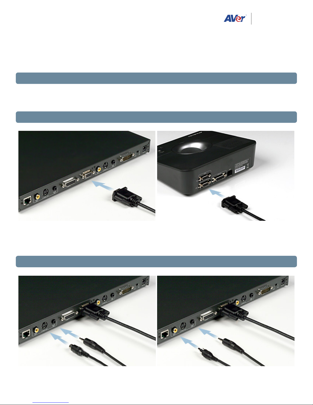
2. Connecting a VGA Display Device (Recommended Connection Method)
Connect the VGA input port of the display device to either VGA OUT 1 (main system) or VGA OUT 2 (Table Hub). Both
VGA OUT 1 and VGA OUT 2 can be used at the same time. Shared data and captured images will be displayed thru VGA
OUT 2 when implementing dual display mode.
3. Connecting a TV Display Device (Alternate Method)
1
Locate the S-VIDEO, VIDEO, or SCART RGB input of the TV/LCD monitor and connect it to AVer H300/H100 using the
appropriate cable.
• Make sure the NTSC/PAL switch is set to the proper TV format.
• For better video quality, we recommend using the S-VIDEO connection if available.
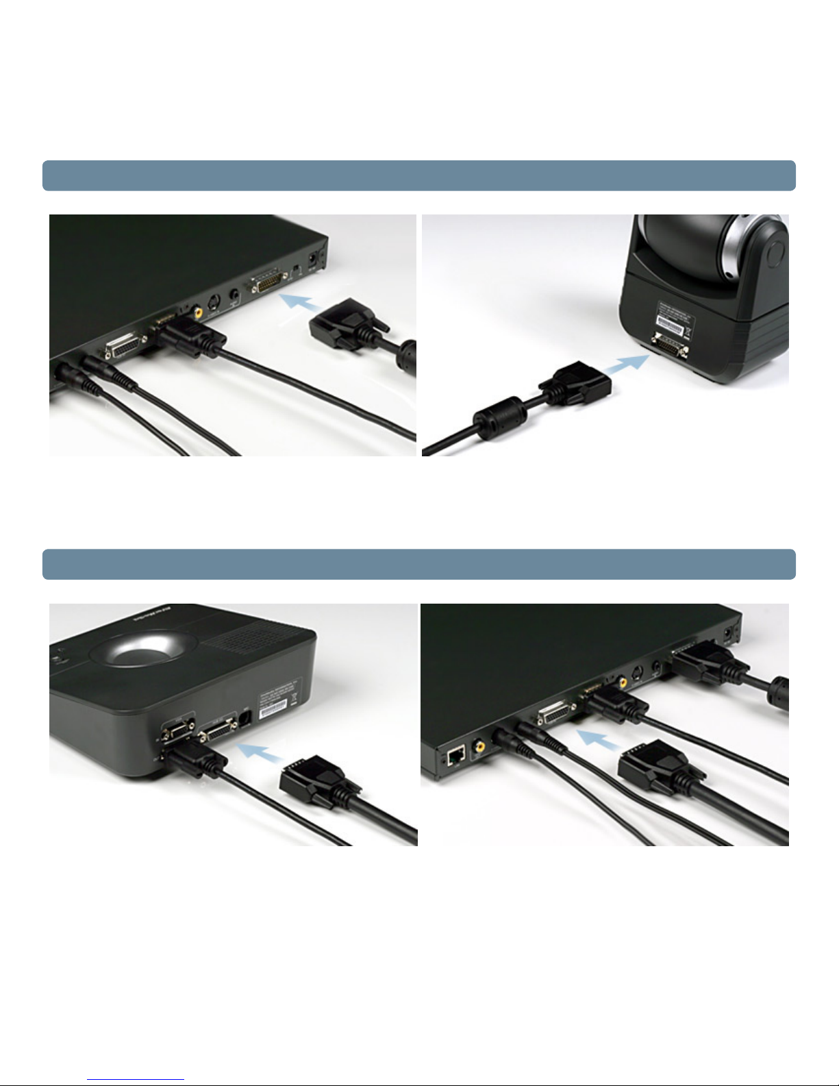
4. Connecting the Camera and Main System
Locate the CAMERA port on the camera and connect it to the CAMERA port of the main system.
• The included 26 Pin-D Sub cable (DB26 female/female) is 5 ft long
5. Connecting the Table Hub and Main System
Connect the HUB I/O port of the table hub to the HUB I/O port of the main system using the included D-Sub cable.
• The included 26 Pin-D Sub cable (DB26 male/male) is 15 ft long
2
 Loading...