

Page 1

ATM Installation, Upgrades, and Administration
8VLQJ$YD\D0XOWL9DQWDJH™6ROXWLRQV
555-233-124
Issue 5
October 2002
Page 2

Copyright 2002, Avaya Inc.
All Rights Reserved
Notice
Every effort was made to ensur e that the in forma tion in th is docume nt
was complete and accurate at the time of printing. However, information is subject to change.
Preventing Toll Fraud
“Toll fraud” is the unauthorized use of your telecommunications system by an unauthorized party (for example, a person who is not a corporate employee, agent, subcontractor, or is not working on your
company's behalf). Be aw a re that there may be a risk of toll fraud
associated with your system and that, if toll fraud occurs, it can result
in substantial additional charges for your telecommunications services.
Avaya Fraud Intervention
If you suspect that you are being victimized by toll fraud and you need
technical assistance or suppor t, in the U ni ted States and Canada, call
the Technical Service Center's Toll Fraud Intervention Hotline at
1-800-643-2353.
How to Get Help
For additional support telephone numbers, go to the Avaya Web site:
http:/www.avaya.com/support/
If you are:
• Within the United States, click Escalation Lists, which includes
escalation phone numbers within the U SA .
• Outside the United States, click Escalation Lists then click Glo-
bal Escalation List, which includes phone numbers for the
regional Centers of Excellence.
Providing Telecommunications Security
Telecommunications security (of voice, data, and/or video communications) is the prevention of any type of intrusion to (that is, either
unauthorized or malicious access to or use of) your company's telecommunications equi pm ent by some party.
Your company's “telecommunic ations equipment” includes both th is
Avaya product and any other voice/data/video equipment that could be
accessed via this Avaya product (that is, “networked equipment”).
An “outside party” is an yone who is not a corporat e employee, agent,
subcontractor, or is not working on your company's behalf. Whereas, a
“malicious party” is anyone (in cl uding someone who may be otherwise authorized) who accesses your telecommunications equipment
with either malicious or mischievous intent .
Such intrusions may be either to/through synchronous (time-multiplexed and/or circuit-based) or asynchronous (character-, message-, or
packet-based) equipment or interfaces for reasons of:
• Utilization (of capabilities special to the accessed equipment)
• Theft (such as, of intellectual property, financial assets, or tollfacility acces s )
• Eavesdropping (privacy invasions to humans)
• Mischief (troubling, but appare ntl y in noc uous, tampering)
• Harm (such as harmful tampering, data loss or alteration,
regardless of motive or intent)
Be aware that there may be a ri sk of unauthorized intrusions asso ci ated with your system and/or its networked equipment. Also re al iz e
that, if such an intrusion should oc cur, it could result in a variety of
losses to your company (including but not limited to, human/data privacy, intellectual property, material assets, financial resources, labor
costs, and/or legal costs).
Responsibility for Your Company’s Telecommunications Security
The final responsibility for securi ng both this system and its networked equipment rests with you - Avaya’s customer system administrator, your telecommunications peers, and your managers. Base the
fulfillment of your responsibility on acquired knowledge and
resources from a variety of sources incl udi ng but not limited to:
• Installation documents
• System administration documents
• Security documents
• Hardware-/s oftware-based security tools
• Shared information betwee n you and your peers
• Telecommunications security experts
To prevent intrusions to your telecommunications equipment, you and
your peers should carefully pro gra m a nd c onfi gure:
• Your Avaya-provided telecommunications systems and their
interfaces
• Your Avaya-provided software applications, as well as their
underlying hardw ar e/software platforms and interfaces
• Any other equipment ne tworked to your Avaya products.
Voice Over Inte rn et Protocol ( VoI P)
If the equipment supports Voice over Internet Protocol (VoIP) facilities, you may experience c ert ai n compromises in performa nc e, rel iability and security, even when the equipm e n t performs as warranted.
These compromises may become more acute if you fail to follow
Avaya's recommendations for configuration, operation an d use of the
equipment. YOU ACKNOWLEDGE THAT YOU ARE AWARE OF
THESE RISKS AND THA T YOU HAVE DETERMINED THEY
ARE ACCEPTABLE FOR YOUR APPLICATION OF THE EQUIPMENT. YOU ALSO ACKNOWLEDGE THAT, UNLESS
EXPRESSLY PROVIDED IN ANOTHER AGREEMENT, YOU
ARE SOLELY RESPONSIBLE FOR (1) ENSURING THAT YOUR
NETWORKS AND SYSTEMS ARE ADEQUATELY SECURED
AGAINST UNAUTHORIZED INTRUSION AND (2) BACKING
UP YOUR DATA AND FILES.
Standards Compliance
Avaya Inc. is not responsible for any radio or television interference
caused by unauthorize d m odifications of this equipment or the substitution or attachment of connecti n g cab les and equipment other than
those specif ied by Avaya Inc. The cor rec ti on of i nter fer enc e c aused by
such unauthorized modifi ca t ions, substitution or attachmen t will be
the responsibility of the user. Pursuant to Part 15 of the Federal Communications Commission (FCC) Rules, the user is cautioned that
changes or modifications not expressly approved by Avaya Inc. could
void the user’s authority to operate this equipment.
Product Safety Standards
This product complies with and co nf o r ms to the fo llowing international Product Safety standards as applicable:
Safety of Information Technology Equipment, IEC 60950, 3rd Edition
including all relevant national deviations as listed in Compliance with
IEC for Electrical Equipment (IECEE) CB-96A.
Page 3

Safety of Information Technology Equipment , CAN/CSA-C22.2 No.
60950-00 / UL 60950, 3rd Editio n
Safety Requirements for Custome r Equipment, ACA Technical Standard (TS) 001 - 1997
One or more of the following Mexican national standards, as applicable: NOM 001 SCFI 1993, NOM SCFI 016 1993, NOM 019 SCFI
1998
The equipment describe d i n thi s document may contain Class 1
LASER Device(s). These devices comply with the following standards:
EN 60825-1, Edition 1. 1, 19 98-01
21 CFR 1040.10 and CFR 1040 .11.
The LASER devices o perate within the follow ing parameters:
• Maximum power output: -5 dBm to -8 dB m
• Center Wavelength: 1310 nm to 1360 nm
Luokan 1 Laserlaite
Klass 1 Laser Apparat
Use of controls or adjustments or performance of proced ures other
than those specified herein may result in hazardous radiation exposures. Contact your Avaya representative for more laser product information.
Electromagnetic Compatibility (EM C) Standards
This product complies with and conforms to the following international EMC standards and all relevant national deviations:
Limits and Methods of Measurement of Radio Interference of Information Technology Equipment, CISPR 22:1997 and EN55022:1998.
Information Technology Equipment – Immunity Characteristics –
Limits and Methods of Measurement, CISPR 24:1997 and
EN55024:1998, including:
• Electrostatic Discharge (ESD) IEC 61000-4-2
• Radiated Immunity IE C 61000-4-3
• Electrical Fast Transient IEC 61000-4-4
• Lightning Effects IEC 61000-4-5
• Conducted Immunity IEC 61000-4-6
• Mains Frequency Magnetic Field IEC 61 000-4-8
• Voltag e D ips and Variations IEC 61000-4-11
• Powerline Harmonics IEC 61000-3-2
• Voltag e Flu ct ua ti ons a nd Fli c ker IEC 61000-3-3
Federal Communications Commission Statement
Part 15:
Note: This equipment has been tested and found to comply with
the limits for a Class A digital device, pursuant to Pa rt 15 of the
FCC Rules. These limits are designed to provide reasonable protection against harmful interference when the equipme n t is op er ated in a commercial environme n t . This eq u ip ment generates,
uses, and can radiate radio frequency energy and, if not installed
and used in accordance with the instruction manual, may cause
harmful interference to radio communications. Operation of this
equipment in a r esidential ar ea is likely to caus e harmful interference in which case the user will be required to correct the interference at his own expense.
Part 68: Answer-Supervision Signaling. Allowing this equipment to
be operated in a manner that does not provide proper answer-supervision signaling is in violation of Part 68 rules. Thi s equi pm e nt returns
answer-supervision signals to the pub lic sw it c hed network when:
• answered by the called statio n,
• answered by the attendant, or
• routed to a recorded announcement that can be admini st ered by
the customer premises equipment (CPE) user.
This equipment returns an sw er-supervision signals on all direct
inward dialed (DID) calls forwarde d back to the pub lic switche d telephone network. Permissible ex ce pt ion s are :
• A call is unanswered.
• A busy tone is received.
• A reorder tone is received.
Avaya attests that this registered equipment is capable of providing
users access to int erstate providers of operato r services th rough the use
of access codes. Modification of this equipment by call aggregators to
block access dialing codes is a vi ol ation of the Telephone Operator
Consumers Act of 1990.
This equipm ent complie s wi th Part 68 of th e F C C Rules. On the rear
of this equipment is a label that contains, among other information, the
FCC registration number and ringer equivalence number (REN) for
this equipment. If req uest ed, this information mu st be provided to the
telephone compan y.
The REN is used to determine the qua nt it y of de vices which may be
connected to the telephone line. Excessive RENs on the telephone line
may result in devices not ringing in response to an incoming call. In
most, but not all areas, the sum of REN s should not exceed 5.0. To be
certain of the num ber of devices that may be connected to a line, as
determined by the total RENs, contact the local telephone company.
REN is not required for some t ype s of analog or digital facilities.
Means of Connection
Connection of this equipment to the telephone network is shown in the
following table.
Manufacturer’s Port
Identifier
FIC Code SOC/REN/
A.S. Code
Network
Jacks
Off/On premises station OL13C 9.0F RJ2GX,
RJ21X,
RJ11C
DID trunk 02RV2-T 0.0B RJ2GX,
RJ21X
CO trunk 02GS2 0.3A RJ21X
CO trunk 02LS2 0.3A RJ21X
Tie trunk TL31M 9.0F RJ2G X
Basic Rate Interface 02IS5 6.0F, 6.0Y RJ49C
1.544 digital interface 04DU9-BN,
1KN, 1SN
6.0F RJ48C,
RJ48M
120A2 channel service unit 04DU9-DN 6.0Y RJ48C
TM
If the terminal equipment (for example, the MultiVantage
Solution
equipment) cause s harm to the telephone n et w ork, the telephone com pany will notify you in advance that temporary discontinuance of service may be required . Bu t if a dvance notice is not pract ic al , the
telephone company will notify the customer as soon as possible. Also,
you will be advised of your right to file a complaint with the FCC if
you believe it is ne cessary.
Page 4

The telephone company may make changes in its facilities, equipment,
operations or procedures tha t co uld affect the operation of the equipment. If this happens, the telephone company will provide advance
notice in order for you to make necessary modifications to main tain
uninterrupted service.
TM
All MultiVantage
system products are compliant with FCC Part 68,
but many have been registered with the FCC before the SDoC process
was available. A list of all Avaya registered products may be found at:
http://www.part68.org/
If trouble is experienced w i th t his equipment, for repair or wa rra nt y
information, please contact the Technical Service Center at 1-800-2422121 or contact your local Avaya representative. If the equipm ent is
causing harm to the telephon e network, the telephone com pa ny may
request that you disconnec t th e equipment until the pro ble m is
resolved.
A plug and jack used to connect this equipment to the premises wiring
and telephone network must comply with the applicable FCC Part 68
rules and requirements adopted by the ACTA. A compliant telephone
cord and modular plu g is provided with this product. It is designed to
be connected to a compatible modular jack that is also compliant.
It is recommended that repa irs be performed by Avaya certified technicians.
The equipment cannot be use d on public coin phone service prov ide d
by the telephone com pany. Connection to party line service is sub je ct
to state tariffs. Con tact the state public utility commission, public service commission or corpor ation commission for informa ti on .
This equipmen t, if it uses a telephone receiver, is hearing ai d compatible.
Canadian Department of Communications (DOC) Interfe rence
Information
This Class A digital appar at us complies with Canadian I CE S -003.
Cet appareil nu mérique de la classe A est conform e à la norme
NMB-003 du Canada.
by conducting a search using “Avaya” as manufact urer.
European Union Declarations of Conformity
Avaya Inc. declares that the equipment sp ecified in this document
bearing the “CE” (Conformité Europeénne) mark conforms to the
European Union Radio and Telecommunications Terminal Equipment
Directive (1999/5/EC), including the Electromagnetic Compatibility
Directive (89/336/EEC) and Low Voltage Directive (73/23/EEC). This
equipment has been certified to meet CTR3 Basic Rate Interface (BRI)
and CTR4 Primary Rate Interface (PRI) and subsets thereof in CTR12
and CTR13, as applic ab le.
Copies of these Declarations of Conformity (DoCs) can be obta in ed
by contacting your local sale s representative and are available on the
following Web site:
http://support.avaya.com/elmodocs2/DoC/IDoC/index.jhtml/
Japan
This is a Class A product based on the standard of the Voluntary Control Council for Interference by Information Technology Equipment
(VCCI). If this equipment is used in a d o mestic environment, ra d io
disturbance may occur, in which case, the user may be required to take
corrective act ions.
This equipment meets the applicable Industry Canada Terminal Equipment Technical Specificati on s. Th is is co nf irmed by the registration
number. The abbreviation, IC, before the registration number signifies
that registration was performed based on a Declaration of Conformity
indicating that Industry Canada technical specifica ti ons were met. It
does not imply that Industry Canada app roved the equipment.
DECLARATIONS OF CONFORMITY
United States FCC Part 68 Supplier’s Declaration of Conformity
(SDoC)
Avaya Inc. in the Unite d St ates of America hereby certifies that th e
equipment describe d in thi s document and bearing a TIA TSB-168
label identification number complies with the FCC’s Rules and Regulations 47 CFR Part 68, and the A dm i n i strative Council on Terminal
Attachments (ACTA) adopted technical cri t er ia.
Avaya further asserts that Avaya handset-equipped terminal equipment described in this docu m ent com plies with Paragraph 68.316 of
the FCC Rules and Regulations de fining Hearing Aid Compatibi li ty
and is deemed comp atible with hearing a ids.
Copies of SDoCs signed by the Responsible Party in the U. S. can be
obtained by contacting your local sales representative a nd are available on the following Web site:
http://support.avaya.com/elmodocs2/DoC/SDoC/index.jhtml/
To order copies of this and other documents:
Call: Avaya Publications Center
Voice 1.800.457.1235 or 1.207.866.6701
FAX 1.800.457.1764 or 1.207.626.7269
Write: Globalwar e Solutions
200 Ward Hill Av enue
Haverhill, MA 01835 USA
Attention: Avaya Account Management
E-mail: totalware @gwsmail.com
Page 5

Contents
About This Book ix
■ Overview x
■ Organization xi
■ Conventions used in this book xii
■ How to get this book xiv
■ How to get technical assistance xiv
■ Security xv
■ Antistatic Protection xvi
■ Remove/Install circuit packs xvi
■ Trademarks xvi
■ Tell us what you think xvi
1 Preparing for Installation and Upgrades 1-1
■ Request Address Information 1-2
■ Review Configuration and Equipment 1-2
■ Determine ATM Switch Suitability 1-13
■ Schedule Installation or Upgrade 1-18
2 Installing a DEFINITY Server
ATM-CES 2-1
■ Equipment Installation 2-1
■ NAA1 Fiber Optic Circuit Pack (csi models only) 2-3
3 Installing a DEFINITY Server
ATM-PNC 3-1
■ Installing Equipment 3-1
■ Installing and Testing Network Synchronization 3-4
■ Setting Up ATM Network Duplication 3-32
■ Installing a WAN Spare Processor 3-36
■ Administration 3-42
Issue 5 October 2002 v555-233-124
Page 6

Contents
4 Upgrading to ATM-PNC 4-1
■ Preparation 4-1
■ Upgrading DEFINITY Server R
with CSS to ATM-PNC 4-3
■ Administration screens 4-12
5 Administering ATM-PNC and
ATM-CES 5-1
■ Accessing Switches for Administration 5-1
■ Acquiring ATM Addresses 5-2
■ Administering ATM Switch 5-4
■ Administering DEFINITY Server 5-4
■ Final Checklist and Test 5-33
6 Troubleshooting 6-1
■ Contact information 6-2
■ Serviceability 6-4
■ Alarms and errors 6-15
■ Troubleshooting ATM-CES 6-17
■ Troubleshooting ATM-PNC 6-30
A Baselining the Customer’s Configuration A-1
■ ATM Switch Administration A-1
■ Interconnections A-2
■ DEFINITY Server Administration Worksheet A-3
555-233-124vi Issue 5 October 2002
Page 7

Contents
B ATM Switch Feature Interactions B-1
■ Location-related Interactions B-1
■ Features Supported B-7
■ Features Not Supported B-10
■ Delay Interactions B-11
■ ATM Feature Interactions B-20
■ Cross-product Compati bili ty B-25
GL Glossary and Abbreviations GL-1
IN Index IN-1
Issue 5 October 2002 vii555-233-124
Page 8

Contents
555-233-124viii Issue 5 October 2002
Page 9

About This Book
This book provides procedures for installing ATM switches and upgrading an
®
existing Avaya DEFINITY
Server to an Avaya MultiVantage on DEFINITY
Server ATM-PNC or ATM-CES. It specifically covers:
■ Installing a new Avaya DEFINITY Server that uses ATM-PNC
■ Replacing the center stage switch (CSS), the central interface between the
PPN and EPNs, with ATM-PNC
■ Upgrading Release 6.3, Release 7, Release 8, Release 9, and Release 10
DEFINITY ATM-PNC to Avaya MultiVant age on DEF INITY ATM-PNC
■ Adding ATM-CES
■ Installing an ATM WAN spare processor (WSP).
The information in this book is intended for use by
■ Avaya and channel partner trained field installation and maintenance
personnel
■ Technical Services Center (TSC) and Global Service Organization (GSO)
personnel
■ InterNetwork Systems (INS) engineers and technicians
■ Sales and Design Support Center (SDSC) personnel
■ Data Services Support Center (DSSC)
■ Sales associates
■ Avaya channel partners.
Issue 5 October 2002 ix555-233-124
Page 10

About This Book
Overview
The Avaya MultiVantage on DEFINITY ATM (asynchronous transfer mode)
combines portions of the Avaya DEFINITY Server with an ATM switch platform
that meets specific criteria. DEFINITY ATM offers both intraswitch and interswitch
ATM solutions. The intraswitch solution is called the ATM port network
connectivity, or ATM-PNC, and the interswitch solution is called ATM circuit
emulation service, or ATM-CES. ATM-PNC is only available on the R6.3r or later
platform.
ATM-PNC provides an alternative to either the direct connect or center stage
switch configurations for connecting the processor port network (PPN) to one or
more expansion port networks (EPNs). ATM-PNC is available with four DEFINITY
Server reliability options—standard, high, ATM network duplication, and critical.
Customers must choose whether they want direct connect, CSS, or ATM-PNC. It
is not possible to mix configurations in the same DEFINITY Server R.
ATM-CES lets the DEFINITY Server emulate an ISDN-PRI trunk on an AT M
facility. These virtual trunks can serve as integrated access, tandem, or tie trunks.
ATM-CES emulates up to 8 ISDN spans on a single OC-3/STM-1 ATM interface.
ATM wide area network (ATM-WAN) extends the port network connectivity
beyond a single ATM switch over large distances. This allows you to use either a
private ATM network, public WAN or a combination of both. Several networked
ATM devices can be used as effectively as a single ATM switch for inter-port
network connectivity.
The DEFINITY Server can connect through several ATM switch types, many of
which are sold through Avaya’s InterNetworking Systems (INS) channel, formerly
know as DNS. Also, DEFINITY Servers are designed to work seamlessly with
non-Avaya ATM switches that meet ATM standards set by the European Union.
For more information on Avaya ATM switches, go to the Avaya Inc. Web site
(http://www.avaya.com) and click on Solutions, Products & Services > Products
A-Z > DEFINITY
■ Avaya M770 Multifunction Switch
■ Avaya PacketStar AC 60 MultiService Media Gateway or PS AX1250
®
ATM Solutions. Examples include the following switches:
MultiService Media Gateway (access concentrators)
x Issue 5 October 2002
555-233-124
Page 11

Organization
Organization
This book contains 6 chapters and 2 appendices:
■ Chapter 1, ‘‘Preparing for Installation and Upgrades’’ describes the
■ Chapter 2, ‘‘Installing a DEFINITY Server ATM-CES’’ provides a procedure
■ Chapter 3, ‘‘Installing a DEFINITY Server ATM-PNC’’ provides a procedure
preparation necessary before an installation and upgrade, including
— network design considerations, including SVCs generated and
network impacts that can restrict ATM switch
— interactions among various Avaya organizations to prepare the
customer site for equipment, translations, and scheduling upgrades
and new installations
— calculating the suitability of various Avaya ATM switches.
for
— hardware installation: ATM circuit packs and the ATM switch.
— cabling (I/O connector, fiber optic cables).
for
— hardware installation: ATM circuit packs, T1 or E1 synchronization
splitter, the ATM switch.
— cabling (I/O connector, fiber optic cables)
— ATM network duplication
— WAN spare processor.
■ Chapter 4, ‘‘Upgrading to ATM-PNC’’ describes the preparation and
various upgrade paths for the following upgrades:
— center stage switch to an Avaya MultiVantage on DEFINITY
ATM-PNC
— Release 6.3, Release 7, Release 8, , Release 9, and Release 10
Avaya DEFINITY ATM-PNC to Avaya MultiVantage ATM-PNC.
■ Chapter 5, ‘‘Administering ATM-PNC and ATM-CES’’ provides the
step-by-step procedures for administering
— ATM port network connectivity (ATM-PNC)
— ATM circuit emulation service (ATM-CES).
■ Chapter 6, ‘‘Troubleshooting’’ describes troubleshooting scenarios and
offers suggestions for isolating, fixing, and clearing DEFINITY Server
alarms and errors for
— DEFINITY Server administration
— ATM-related synchronization
— ATM switch administration .
Issue 5 October 2002
xi555-233-124
Page 12

About This Book
■ Appendix A, ‘‘Baselining the Customer’s Configuration’’ provides a
worksheet to log the translations and administration information for
— DEFINITY Server configuration s
— Lightwave interface units.
■ Appendix B, ‘‘ATM Switch Feature Interactions’’ offers a quick-reference
guide to the features supported and not supported and interactions among
the DEFINITY Server’s features.
Conventions used in this book
Systems and circuit packs
■ The word “system” is a general term encompassing all references to the
Avaya DEFINITY Server R running Avaya MultiVantage Software.
■ Circuit pack codes (for example, TN780 or TN2182B) are shown with the
minimum acceptable alphabetic suffix (like the “B” in the code TN2182B).
Typographic
Other terms and conventions might help you use this book.
Generally, an alphabetic suffix higher than that shown is also acceptable.
However, not every vintage of either the minimum suffix or a higher suffix
code is necessarily accep tab le. A suffix of “P” means that firmware can be
downloaded to that circuit pack.
■ The term “ASAI” is synonymous with the newer CallVisor ASAI.
■ The term “cabinet” generally refers to the MCC1 (multi-carrier) cabinet.
■ UUCSS refers to a circuit pack address in cabinet-carrier-slot order.
■ Commands are printed in bold face as follows: command.
We show complete commands in this book, but you can usually type an
abbreviated version of the command. For example, list configuration
station can be typed as list config sta.
■ Screen displays and names of fields are printed in constant width as
follows: screen display.
A screen is any form displayed on your computer or terminal monitor.
■ Variables are printed in italics as follows: variable.
■ Keys and buttons are printed as follows: KEY.
■ To move to a certain field, you can use the TAB key, arrows, or the ENTER
key (the
xii Issue 5 October 2002
ENTER key may appear as the RETURN key on your keyboard).
555-233-124
Page 13

Conventions used in this book
■ If you use terminal emulation software, you need to determine what keys
correspond to
■ In this book we use the terms “telephone” and “voice terminal” to refer to
phones.
■ If you need help constructing a command or completing a field entry,
remember to use
ENTER, RETURN, CANCEL, HELP, NEXT PAGE, etc.
HELP.
■ The status line or message line can be found near the bottom of your
■ When a procedure requires you to press ENTER to save your changes, the
Admonishments
Admonishments in this book have the following meanings:
!
CAUTION:
Denotes possible harm to software, possible loss of data, or possible service
interruptions.
— When you press
HELP at any point on the command line, a list of
available commands appea rs.
— When you press HELP with your cursor in a field on a screen, a list of
valid entries for that field appears.
monitor display. This is where the system displays messages for you.
Check the message line to see how the system responds to your input.
Write down the message if you need to call our helpline.
screen you were working on clears and the cursor returns to the command
prompt.
The message line shows “command successfully completed” to
indicate that the system accepted your changes.
!
WARNING:
Denotes possible harm to hardware or equipment.
!
DANGER:
Denotes possible harm or injury to your body.
Physical dimensions
■ Physical dimensions in this book are in inches (in.) followed by metric
centimeters (cm) in parentheses.
■ Wire gauge measurements are in AWG followed by the cross-sectional
area in millimeters squar ed (mm
2
) in parentheses.
Issue 5 October 2002
xiii555-233-124
Page 14

About This Book
How to get this book
On the Web
If you have internet access, you can view and download the latest version of this
book. To view the book, you must have a copy of Acrobat Reader.
To access the latest version:
1. At your browser, go to the Avaya web site:
http://www.avaya.com
2. Select Support.
3. Select Online Services.
4. Select Documentation.
5. Select Recent Documents.
6. Scroll down to find the latest release of DEFINITY or Avaya MultiVantage
Software documents.
7. Search for the document number to view the latest version of the book.
Non-Web
This book and any other DEFINITY or Avaya MultiVantage Software books can be
ordered directly from:
Globalware Solutions
200 Ward Hill Avenue
Haverhill, MA 01835 USA
+1-800-457-1235 (phone)
+1-800-457-1764 (fax)
Non-800 numbers:
+1 410-568-3680 (phone)
+1 410-891-0207 (phone)
How to get technical assistance
For additional support and trouble escalation:
1. At your browser, go to the Avaya web site:
http://www.avaya.com
2. Select Support
xiv Issue 5 October 2002
555-233-124
Page 15

Security
3. If you are:
■ Within the United States, click Escalation Lists, which include s
escalation phone numbers within the USA.
■ Outside the United States, click Escalation Lists then click
Global Escalation List, which includes phone numbers for the
regional Centers of Excellence.
If you do not have Web access, use the phone numbers below.
NOTE:
You may need to purchase an extended service agreement to use some of
these resources. See your Avaya representative for more information.
Table 1. Avaya support
Support Number
Security
■ DEFINITY Helpline (for help with feature
+1-800-225-7585
administration and system applications)
■ Avaya National Customer Care Center Support
+1-800-242-2121
Line (for help with maintenance and repair)
■ Avaya Toll Fraud Intervention +1-800-643-2353
■ Avaya Corporate Security +1-800-822-9009
+1-925-224-3401
■ International Technical Assistance Center (ITAC) +905-943-8801
For all international resources, contact your local Avaya authorized dealer for any
additional help and questions.
Continued on next page
To ensure the greatest security possible for customers, Avaya Inc. offers services
that can reduce toll-fraud liabilities. Contact your Avaya Inc. representative for
more security information.
Login security is an attribute of the MultiVantage Software. Existing passwords
expire 24 hours after installation.
For Access Security Gateway (ASG), see Appendix B, ‘‘Access Security
Gateway’’.
Issue 5 October 2002
xv555-233-124
Page 16

About This Book
Antistatic Protection
!
CAUTION:
When handling circuit packs or any components of a DEFINITY System,
always wear an antistatic wrist ground strap. Connect the strap to an
approved ground such as an unpainted metal surface on the DEFINITY
System.
Remove/Install circuit packs
!
CAUTION:
When the power is on:
■ The control circuit packs cannot be removed or installed.
■ The port circuit packs can be removed or installed.
Trademarks
All trademarks identified by ® or ™ are registered trademarks or trademarks,
respectively, of Avaya Inc. All other trademarks are the property of their respective
owners.
Tell us what you think
Let us know what you like or don’t like about this book. Although we can’t respond
personally to all your feedback, we promise we will read each response we
receive.
Write to us at: Avaya
Fax to: 303-538-1741
Send email to: document@avaya.com
Product Documentation Group
1300 W. 120th St.
Westminster, CO 80234 USA
xvi Issue 5 October 2002
555-233-124
Page 17

Preparing for Installation and Upgrades
This chapter contains information on preparing for the installation or upgrade to
®
Avaya M ultiVantage software running on an Avaya DEFINITY
Server A TM P ort
Network Connectivity (ATM-PNC) and ATM Circuit Emulation Service (ATM-CES).
Common activities to either install or upgrade new ATM-PNCs or ATM-CESs
include:
■ Request Address Information
■ Review Configuration and Equipment
■ Determine ATM Switch Suitability
■ Schedule Installation or Upgrade
Preparing for a DEFINITY Server ATM switch installation or upgrade involves
coordinating the efforts among the following people and organizations:
■ The customer
■ The project manager
■ NetCare® Professional Services (NPS)
■ Avaya Technical Service Center (TSC) or Global Strategic Opportunities
(GSO) Division
■ ATM switch technic ian
■ Avaya channel partner, if applicable
Issue 5 October 2002 1-1555-233-124
Page 18

Preparing for Installation and Upgrades
Request Address Information
The complete DEFINITY Server tra ns lat io ns requi r e precuto ve r admini s trat io n,
which, in turn, requires a customer address scheme, specifically the ATM
addresses for theTN2305X/TN2306X ATM interface circuit pack(s). The address
of the EPN is automatically read by the local ATM switch, using the address
registration procedure defined in Integrated Local Management Interface (ILMI). If
field technicians do not have the login permissions required to obtain the EPN’s
ATM address(es) directly from the ATM switch(es), the customer or ATM switch
installe r must provide that information.
Review Configuration and Equipment
Figure 1-1 shows an example of the basic ATM connections for the DEFINITY
Server R and DEFINITY Server CSI using ATM-PNC and ATM-CES. For more
detailed connection diagrams of the reliability options, refer to ‘‘DEFINITY Server
configurations’’ on page 1-9.
1-2 Issue 5 October 2002
555-233-124
Page 19

Review Configuration and Equipment
1
2 2
6
7
2
2
9
8
2
7
3
2 2
cydaaccs LJK 111099
6
4
6
5
4
6
Figure Notes
1. DEFINITY Server PPN-1 (R)
2. Avaya ATM switch
3. ATM network (the cloud)
4. DEFINITY Server EPN in
MCC1
5. DEFINITY Server EPN in SCC1
6. ATM-PNC
7. ATM-CES
8. ATM-PNC and ATM-CES
9. DEFINITY Server PPN-2 (CSI)
Figure 1-1. Example of an ATM-PNC and ATM-CES configuration
Issue 5 October 2002
1-3555-233-124
Page 20

Preparing for Installation and Upgrades
Required Hardware
Table 1-1 lists the required equipment for standard, high, critical reliability, and
ATM network duplication confi gur ations .
Table 1-1. Min. required equipment for Avaya MultiVantage ATM-PNC configurations
Reliability level
Critical/ATM
Equipment
ATM switch 1 1 2
TN2305X/TN230XB ATM interface
for each PN (see Redesigned ATM
interface circuit packs)
2
T1 or E1 synchronizati on splitter
Synchronization splitt ers)
SC-connected fiber optic cable (see)
TN771 maintenance/test circuit pack
(see
Standard High
1
1 2 (PPN)
1 (each EPN)
11 1
3
1 2 (PPN)
1 (each EPN)
4
Network Duplication
2
2
1
1. TN2305B (multimode fibe r); TN2 306B (sing le-mod e fiber) f or ATM-PNC. Th e B-suff ix circui t pack is
backward-compatible with, but does not replace the TN2305 or TN2306 circuit packs.
2. The number and uses o f the sy nc hron iz ati on s pl itte r de pen d on the configuration an d the source(s)
from which primary and secondary syn chronization i s derived. You ma y need 1 sync spl itter per ATM
switch. DS1 synchronization requires either no sync splitter or up to a number twice the number of
sites.
3. Existing fiber optic cable may require an ST-to-SC adapter, depending on the interface at the ATM
switch. The TN2305X/TN2306X circuit pack requires an SC connector.
4. For network duplication; required for systems supporting PRI, BRI, or ASAI.
1-4 Issue 5 October 2002
555-233-124
Page 21

Review Configuration and Equipment
Redesigned ATM interface circuit packs
■ The TN2305B and TN2306B circuit packs do not replace the TN2305 and
TN2306 circuit packs, respectively. Either circuit pack can be used in all
platforms, but the TN2305B or TN2306B is required for critical reliability
with WAN Spare Processors (WSPs).
■ Y ou do not receive the TN2305B and TN2306B ATM interface circuit packs
as automatic upgrades.
The redesigned TN2305B/TN2306B ATM interface circuit packs have more
capabilities and resources:
■ Firmware monitor port on the backplane of the circuit packs
■ Spare lead for WSP applications
■ Processor speed increased to 66 megahertz (MHz.)
■ Increased hardware vintage bits
■ ATM-network duplication
The increased functionality is available to both ATM-PNC and ATM-CES
applications. However, both circuit packs can also function in systems designed
and installed earlier than this release.
Firmware monitor port
Figure 1- 2 shows the location of the firmware monitor port on the backplane of the
circuit pack. You can attach a monitor cable to the ATM expansion circuit pack
without removing the circuit pack from its carrier.
NOTE:
The TN2305/2306 circuit packs also have a firmware monitor header
located on the circuit pack. This header functions the same as the
redesigned backplane connector (Figure 1-2), but requires busying out and
unseating the circuit pack to attach the monitor cable.
Issue 5 October 2002
1-5555-233-124
Page 22

Preparing for Installation and Upgrades
1
Figure Notes
1. DEFINITY Server
2. 258A 6-port Amphenol to
RS-232 adapter
(Comcode 102605136)
6
2
4
3
1
5
cydfatm6 LJK 051801
3. D8W (8-wire) cable
4. 355A RS-232 to 25-pin serial adapter
(Comcode 407590785)
5. Laptop computer
Figure 1-2. TN2305B and TN2306B firmware monitor port
Use Figure 1-2 and the following procedure to access firmware monitor port on
the TN2305B or TN2306B circuit packs only:
1. Connect the 258A 6-port Amphenol adapter to the port slot on the
backplane corresponding to the TN2305B or TN2306B circuit pack.
2. Connect a D8W cable to port 1 of the 258A adapter.
3. Connect the other end of the D8W cable to the RS-232 side of the 355A
adapter.
1. Connect the 25-pin serial connector on the 355A adapter to a serial port on
the computer.
2. At the computer set the baud rate for the serial port to 38,400 (38.4K).
1-6 Issue 5 October 2002
555-233-124
Page 23

Review Configuration and Equipment
Spare lead
The spare lead allows the B-suffix ATM circuit packs to function seamlessly in the
ATM WAN Spare Processor (WSP) application. It uses pin number 139
(AATOKEN) and is required in
■ multicarrier cabinets (e.g., Avaya MCC1 Media Gateways)
with
■ Avaya MultiVantage software running on a DEFINITY Server R.
Processor speed increased
The circuit pack processor speed is 66 megahertz (MHz.)
Increased hardware vintage bits
The range of available hardware vintage bits is now 7, increasing the number of
possible vintage values to 127.
ATM-network duplication
WAN spare processor is compatible with all Avaya DEFINITY Server reliability
options for complete ATM-network duplication.
Synchronization splitters
To test the synchronization splitters, you need the following equipment:
■ Phoenix 1541C Test Set with accessory cord kit
■ Phoenix 5575A T1 Test Set with cord kit or equivalent
■ 700A DS1 CPE Loopback Jack
■ 103A block
■ 1541CC cable kit
■ RJ45-to-Bantam test cable from the 1541CC cable kit
■ System capacities
Table 1-2 lists the maximum number of TN2305X/TN2306X circuit packs allowed
in a DEFINITY Server.
1
(comcode 10798867)
1. See Maintenance for Avaya MultiVantage and DEFINITY Server R, Chapter 6, DS1 Loopbac k Test
for more information.
Issue 5 October 2002
1-7555-233-124
Page 24

Preparing for Installation and Upgrades
Table 1-2. Maximum number of TN2305X/TN2306X circuit packs
Maximum ATM circuit
Platform
DEFINITY R 176 88 port networks (for CES) plus 88 port
SI, CSI, or C 6 CES only (no PNC)
packs allowed Description
networks (for PNC)
Fiber-optic cable distances
The fiber-optic cable range is determined by the optical power budget and the
fiber bandwidth. Table 1-3 shows the TN2305X/TN2306X specifications.
Table 1-3. TN2305X/TN2306X fiber-optic specifications
Fiber mode
Parameter
Output optical power max -14 -8 dBm ave rage
Output optical power min (BOL/EOL) -19/-20 -15 dBm average
UnitsMultimode Single mode
Input optical power max -14 -8 dBm average
Input optical power min -30 -31/32.5/34 dBm average
Optical power budget 30-19=11 31-15=16 dBm
Typical range -4 -20 Km
Typical wavelength 1310 1310 nm
Wavelength min/max 1261/1360 1261/1360 nm
Fiber width 62.5/125 62.5/125 um
Connector Duplex SC Duplex SC
Loss per connector 0.2 dB
Fiber cable loss 1 0.5 max (0.33
typical)
Fiber bandwidth 500 10,000 MHz-Km
Reflections 28 dB
IEC 825/CDRH Class 1
compliant
dB/Km
Continued on next page
1-8 Issue 5 October 2002
555-233-124
Page 25

Review Configuration and Equipment
Example
A multimode fiber using an optical power budget of 11 dB and a loss of 1 dB/Km
with no con nectors yields a distance of 11 Km, which is unrealistic. Using a fiber
bandwidth of 500MHz-Km and using the ATM OC-3c symbol rate of 77.5 Mb/s
(data rate 155 Mb/s) yields a distance of 6.4Km. In this case the distance is limited
by the fiber bandwidth.
DEFINITY Server configurations
Figure 1-3, Figure 1-4 on page 1-11, and Figure 1-5 on page 1-12 show the
ATM-PNC connections for standard, high, and critical reliability, respectively.
Issue 5 October 2002
1-9555-233-124
Page 26

Preparing for Installation and Upgrades
10
12
5
9
5
8
10
11
5
1
2
3
7
6
13
5
4
cydaeps7 LJK 020100
Figure Notes
1. T1/E1 sync source (public switched
telephone network—PSTN)
2. Main distribution frame (MDF) or smart
jack
3. Synchron ization splitter.
4. DS1 circuit pack (TN464F)
5. TN2305X/TN2306X circuit packs
6. DEFINITY Server access terminal
7. Timing signal from synchronization
8. Avaya ATM switch (more than
one ATM switch in an
ATM-WAN configuration.)
9. ATM switch access terminal
10. Fiber optic cables from ATM
OC-3/STM-1 interfaces
11. DEFINITY Server EPN
12. Split cabinet EPN
13. DEFINITY Server PPN
splitter through an H600-383 cable to
Avaya ATM switch
Figure 1-3. ATM-PNC connections for standard reliability
1-10 Issue 5 October 2002
555-233-124
Page 27

Review Configuration and Equipment
11 12
5
1
2
3
4
7
6
5
5
Figure Notes
1. T1/E1 sync source (public switched
telephone network—PSTN)
5
8
8
cydaeph4 LJK 020100
5
8. Fiber optic cables to ATM
10
8
9
OC-3/STM-1 interfaces
2. Main distribution frame (MDF) or smart
jack
3. Synchron ization splitter
4. DS1 circuit pack (TN464F)
5. TN2305X/TN2306X circuit packs
6. DEFINITY Server access terminal
9. Avaya ATM switch (more than
one ATM switch in an
ATM-WAN configuration.)
10. ATM switch access terminal
11. DEFINITY Server EPN
12. Split-cabinet EPN
7. Timing signal from synchronization
splitter through an H600-383 cable to
Avaya ATM switch
Figure 1-4. ATM-PNC connections for high reliability
Issue 5 October 2002
1-11555-233-124
Page 28

Preparing for Installation and Upgrades
13
5
10
9
8
1
88
3
7
2
4
5
5
cydaepn3 LJK 020100
14
5
12
5
8
6
88
11
Figure Notes
1. T1/E1 sync source (public switched
telephone network—PSTN)
2. Main distribution frame (MDF) or smart
jack
Synchronization splitter
3.
1
4. DS1 circuit pack (TN464F)
5. TN2305X/TN2306X circuit packs
6. DEFINITY Server access terminal)
8. Fiber optic cables to ATM
interfaces
9. Avaya ATM switch B
10. ATM switch access terminal B
11. Avaya ATM switch A
12. ATM switch access terminal A
13. DEFINITY Server EPN
14. Split-cabinet EPN
7. Timing signal from synchronization
splitter through an H600-383 cable to
Avaya ATM switch
1
You could use 2 separate PSTN sync sources and 2 separate splitters for complete redundancy
Figure 1-5. ATM-PNC connections for critical reliability or ATM network
duplication
1-12 Issue 5 October 2002
555-233-124
Page 29

Determine ATM Switch Suitability
Determine ATM Switch Suitability
To fully support DEFINITY Server ATM-PNC and provide nonblocking ATM
access between all port networks, ATM switches must support at least 400
point-to-multipoint switched virtual connection (SVC) roots or leav es per
OC-3/STM-1 interface. Because different switches have different limits—some
limit roots, some leaves, and some the total, we have developed the Meiners’
Algorithm to determine whether a switch can support a proposed set of port
networks. Note that there are separate versions of the algorithm for Avaya M770
Multifunction switches and for other ATM switches. These algorithms are available
to Avaya personnel as calculators within two Microsoft® Excel spreadsheets.
Personnel with Avaya intranet access may find either of these MS Excel files at
http://info.dr.avaya.com/~meiners/atm.html. Check periodically for updates.
The following directions only apply to the non-M770 version of the algorithm. (See
the spreadsheets for further usage notes.) For best results, use the calculator for
one ATM switch at a time. Use trial and error to set the values in the user-defined
values section until the feasibility indicator reports YES or PROBABLY.
NOTE:
Use of this spreadsheet is no substitute for thinking. Please apply basic
sanity checks to the outcome. ATM switches may have limitations that the
calculator does not consider.
To use the calculator, type the network layout and resource limits for the ATM
switch you are using. Refer to the following caveats as you input your information:
1. Not all ATM switches have limits on all of the values. If a limit does not
apply, enter any very large number (1000000 is good).
2. Some ATM switches (for example, access concentrators) allow a limited
ability to configure the limits. Other switches have fixed limits. If you do not
know the limits, ask the ATM switch vendor.
3. If your ATM switch is handling non-DEFINITY traffic, enter the resource
limits after subtracting the resources used by the non-DEFINITY traffic.
4. If you are using an ATM switch with different limits on different modules or
ports (for example, an Avaya M770 Multifunction Switch):
a. compute the average limits per port to which a DEFINITY port
network is attached.
b. select the port with the most restrictive limitations.
c. enter the system limit as these limits times the number of DEFINITY
port networks attached to that ATM switch.
NOTE:
The more partitioned the limits are, the less accurate are the
results of the spreadsheet.
Issue 5 October 2002
1-13555-233-124
Page 30

Preparing for Installation and Upgrades
5. If you answer "yes" to transit traffic, the calculator may or may not be able
to determine feasibility. If it cannot, the feasibility displays as UNKNOW N.
Table 1-4 shows an example of a calculation.
Table 1-4. Sample calculation
Network Layout
Customer SV
ATM switch M770
Total number of DEFINITY port networks: 20
Number of PNs directly attached to this ATM switch: 8
Is the DEFINITY PPN directly attached to this ATM switch (yes/no) yes
Number of trunks on this ATM switch (inter-ATM-switch
connections)
Any transit traffic through this ATM switch (yes/no) no
Aggregate peak phone calls rate per hour in all directly connected
PNs
Bidirectional aggregate trunk bandwidth in Mbps 155.52
Application bandwidth in kbps needed per port network 128
ATM Switch Resource Limits (see "Limits" sheet for help)
Number of PP SVCs supported: 1000000
Number of PMP (roots) supported: 4096
Number of PMP parties (leaves) supported: 1000000
Number of PMP endpoints (roots+leaves) supported: 1000000
Total number of SVCs (PP+PMP) supported 1000000
Per-port SVC limit (normally based on VCI range) 1000000
Setups per second at <220 ms per setup 1000000
Feasibility YES
Bandwidth limited 1960 calls
1
10000
YES means that this application is okay under any load.
PROBABLY means that this application is okay under any reasonable loads.
Check the constraint tests results to see what kind of loads might be a problem.
NO means that this application is not reasonable. See the Constraint Tests results
to see what resource you are short of. See if you can increase this resource, or
decrease the number of port networks.
1-14 Issue 5 October 2002
555-233-124
Page 31

Determine ATM Switch Suitability
UNKNOWN means that special engineering is required for this application
because of the transit traffic. The special treatment is necessary because the
feasibility depends on the volume of the transit traffic. Making any of the changes
suggested for NO above might make it feasible regardless of the transit traffic.
BANDWIDTH LIMITED means that the aggregate trunk bandwidth is insufficient
to support the theoretical maximum demand. Bandwidth-limited applications are
not recommended unless you are certain that the requested call load will never
exceed the available bandwidth. Make sure you are comfortable with the call limit
for calls to nonlocal port networks (PNs).
Table 1-5. Constants
Timeslots per port network 500
Cache hit ratio 50%
EAL+PACL bandwidth 96
Table 1-6. Computed values
Number of nonlocal port networks 12
Effective number of port networks for PP 19
Effective number of port networks for PMP 16
Number of available timeslots 7920
Per-port SVCs (PP+PMP) needed 557
PP SVCs per PN 3
Total PP SVCs 57
PP cells per second required over trunks 13992
Aggregate cells per second available over trunks 353207
Bandwidth-limited maximum phone calls over trunks 1960
Timeslot-limited maximum phone calls over trunks 2000
Constraint tests
If your calculations do not yield a YES, this section provides the resources of
which you are short. These tests check 9 ATM switch resource limitations against
6 different application scenarios. A 1 in the Test Results (Table 1-8 on page 1-16)
indicates a passed test; a 0 indicates a failed test. To achieve a YES feasibility, all
54 tests must pass. To ac hie ve a PROBABLY, only 27 tests (indicated in bold)
must pass.
Issue 5 October 2002
1-15555-233-124
Page 32

Preparing for Installation and Upgrades
Table 1-7. Application scenarios
Number of 2-party calls 1980 0 0 0 0 990
Number of 3-party calls 0 880 0 0 0 220
Number of 4-party calls 0 0 495 0 0 61
Number of 5-party calls 0 0 0 316 0 19
Number of 6-party calls 0 0 0 0 220 14
Tab le 1-8. Tes t resu lt s
Constraint 1: Timeslots 111111
Constraint 2: PMP roots 111111
Constraint 3: PP 111111
Constraint 4: PMP leaves 111111
Constraint 5: PMP endpoints 111111
Constraint 6: Total SVCs 111111
Constraint 7: Per-port SVCs 111111
Constraint 8:Performance 111111
Constraint 9:Trunk bandwidth 111111
Final notes
The goal is to engineer the network so that in all reasonable applications, you
always run out of DEFINITY Server time slots before running out of ATM switch
resources. This is required to provide acceptable service to the customer.
These calculations factor in phone calls only. There is no specific accommodation
for the ATM SVC cache, or for special features such as music, announcements,
and group paging. The theory behind using 500 as the number of timeslots in a
port network rather than the real number (484) is to allow for a normal amount of
these special features. If you use multiple music on hold, group paging, and so
forth, you may need special engineering.
This calculator determines that an application is PROBABLY feasible if it can
handle reasonable activity mixes. The three columns in Table 1-8 that have bold
entries define what is meant by reasonable. These tests require that the switch be
able to handle a complete suite of 2-party calls, a complete suite of 3-party calls,
and a mixed suite that involves some calls of each type. For best results, your
application should pass all the constraint tests.
1-16 Issue 5 October 2002
555-233-124
Page 33
Determine ATM Switch Suitability
Any ATM switch that processes transit traffic (that is, connections that do not
either originate or terminate on any of the port networks directly attached to it)
may require special engineering. This is possible if the number of trunks on the
ATM switch is more than one. If this is the case, the calculator first attempts to
determine if the application is feasible despite the transit traffic. If it is, it reports
the feasibility as YES or PROBABLY. If not, it reports the feasibility as
UNKNOWN, requiring special engineering.
Known limits of commonly used ATM switches
Use the limits shown in T abl e 1-9 to do your own calculations. To make it easier as
you use the calculator, we suggest that you
1. Select and copy the values from the table in the spreadsheet.
2. Select the values on the sample calculation.
3. Select Edit > Paste Special with the transpose option to paste the values
into the calculator.
NOTE:
These limits are the best we could determine at one time. For each switch,
the example shown is generally the best you can do, assuming you bought
the maximum configuration and you administered it optimally for DEFINITY
(which are not necessarily the default settings). Consult the switch vendor
for confirmation of current limits.
A limit shown as 1000000 means that this ATM switch has no independently
defined limit on this resource.
Table 1-9. Known limits of commonly used ATM switches
Number
Number
Number
of PP
SVCs
Switch
Avaya PacketStar PSAX 1250
Release 5.0 1000000 1000000 1000000 1000 1000000 1000000 1000000
Release 5.1 1000000 1000000 1000000 4000 1000000 1000000 1000000
Release 6 (with
recommended
admin)
supported
400 5000 6666 1000000 1000000 1000000 1000000
Number
of PMP
(roots)
supported
of PMP
parties
(leaves)
supported
of PMP
endpoints
(roots +
leaves)
supported
Total
number
of SVCs
(PP+PMP)
supported
Per-port
SVC limit
(normally
based on
VCI
range)
Continued on next page
Setups/s
at
<220 s/set
up
Issue 5 October 2002
1-17555-233-124
Page 34

Preparing for Installation and Upgrades
Table 1-9. Known limits of commonly used ATM switches (Continued)
Avaya M770 Multifunction r2
Dual Domain
Modules 1&8
Dual Domain
Modules
2-7&9-14
Single Domain 1000000 1024 1000000 1000000 1000000 1000000 1000000
Dual Domain 1000000 4096 1000000 1000000 1000000 1000000 1000000
Fore ASX1000
Release 6 (with
memory model 5)
1000000 4096 1000000 1000000 1000000 1000000 1000000
1000000 2048 1000000 1000000 1000000 1000000 1000000
2048 2048 16384 1000000 1000000 1000000 1000000
Continued on next page
Schedule Installation or Upgrade
Schedule the installation or upgrade with the Avaya Technical Support
Organization (TSO) and NetworkCare® Profe ssio nal Servi ce s (NP S).
1-18 Issue 5 October 2002
555-233-124
Page 35

Installing a DEFINITY Server AT M -C E S
This chapter describes the procedures for installing a new Avaya MultiVantage
software running on an Avaya DEFINITY
simple in that you install the DEFINITY Server, then install the ATM switch and the
TN2305X/TN2306X interface circuit packs. Making it an ATM-CES is done
administratively (refer to Chapter 5, ‘‘Administering ATM-PNC and ATM-CES’’).
NOTE:
ATM-CES works only with TN2305X/TN2306X ATM interface circuit packs.
Equipment Installation
To prepare for a new Avaya MultiVantage on DEFINITY ATM-CES installation,
you need to install the DEFINITY Server first. For instructions on installing a
DEFINITY Server or an Avaya S8100 Media Server, refer to the following
installation books or online information:
■ DEFINITY Made Easy (online at the U RL: http://made-easy.avaya.com)
■ Installation, Upgrades, and Additions for Avaya CMC1 Media Gateway
■ Installation and Upgrades for the Avaya S8100 Media Server with the
Avaya G600 and CMC1 Media Gateways
Review the reliability configurations for Avaya DEFINITY Server ATM (refer to
Figure 1-3 on page 1-10 through Figure 1-5 on page 1-12).
®
Server ATM-CES The procedure is
The slot re s tr i cti o ns f o r a C ES co nf ig u rat i o n ar e si mi l ar t o ISD N -P R I ci r c ui t pa cks.
In PPNs and EPNs, ATM interface circuit packs can occupy any available slot in a
port carrier.
Issue 5 October 2002 2-1555-233-124
Page 36

Installing a DEFINITY Server ATM-CES
Follow the steps in Table 2-1 to ensure that
■ the applicable equipment is installed correctly.
■ the customer’s configuration is properly recorded (use worksheet in
Appendix A, ‘‘Baselining the Customer’s Configuration’’).
Table 2-1. General installation process
√ Step Action Description
1. Install DEFINITY
Server
2. Install ATM switch(es)
or access
concentrators
3. Install ATM interface
circuit pack
4. Route the fiber optic
cables between the
ATM switch and the
DEFINITY Server
PPN and EPNs.
5. Connect the fiber
optic cables
Refer to the appropriate installation book for your platform
See ‘‘DEFINITY Server configurations’’ on page 1-9 for
connection schematics.
Refer to your ATM switch’s quick reference guide. To get a
copy of the quick refere nce gu ide, go to th e Avaya web site
(http://www.avaya.com), clic k on Support , a nd then find t he
page for your Avaya ATM solution.
Insert the TN2305X/TN2306X circuit pack(s) into the
appropriate slot(s).
Follow the fiber pass-through procedure in the appropriate
DEFINITY Server installation book.
!
WARNING:
Be sure that the fiber optic cable is secured so that
the door of the DEFINITY ECS swit ch does n ot pinc h
or bend the cable.
For csi platforms, see ‘‘NAA1 Fiber Opti c Circuit Pack (csi
models only)’’ on pa ge 2-3 for a diagram of the NAA7 board
that routes fiber optic cabling from the back of the switch to
the front.
Connect the fiber optic cables to the ATM switch.
NOTE:
If the installation uses the customer’s existing fiber,
you may need an ST-to-SC adapter (1 included in
Fiber Pass-Through Kit).
2-2 Issue 5 October 2002
Continued on next page
555-233-124
Page 37

NAA1 Fiber Optic Circuit Pack (csi models only)
Table 2-1. General installation process (Continued)
√ Step Action Description
6. Connect the fiber
optic cables to the
ATM interface circuit
packs
7. Record configuration Record DEFINITY Server switch-to-ATM port (port
8. Record fiber
connections
Connect fiber optic cable to the SC connector on the
faceplate of each TN2305X/TN2306X circuit pack in the
DEFINITY Server PPN and EPN.
■ Th e TN 23 05X/T N2306X circuit pack interface requ ires
SC connectors (see Note in Step 5).
■ Do not reuse existing fiber cabling with ST connectors
at both the DEFINITY Serve r and the ATM switch. This
requires an ST-to-SC adapter at both ends. It is better
to order the cable with the SC c on nec tors a t bo th ends.
locations for each ATM circuit pack) in Table A-1 in
Appendix A, ‘‘Baselining the Customer’s Configuration’’.
Record the fiber optic c ab le runs o n th e l igh tw av e i nte rfac e
(LIU) diagram (Figure A-1 in Appendix A, ‘‘Baselining the
Customer’s Configuration’’).
NAA1 Fiber Optic Circuit Pack (csi
models only)
The NAA1 board routes fiber optic connections from the rear of the cabinet
through the front faceplate. The SC fiber connectors that go through the faceplate
connect to the faceplate connectors on the TN2305X/TN2306X ATM circuit pack.
Continued on next page
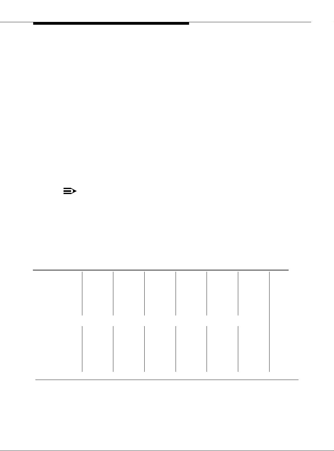
Unpack and Inspect
1. Verify that the equipment is received. See Figure 2-1 on page 2-4. Actual
equipment may vary in appearance and may ship in separate packages.
2. See Table 2-2 on page 2-5 for a list of part Comcodes.
Issue 5 October 2002
2-3555-233-124
Page 38
Installing a DEFINITY Server ATM-CES
2
3
Figure Notes
1. NAA1 circuit pack
2. SC/ST connectors (2x)
3. SC/SC connectors (2x)
AB
AB
4
ckdakit LJK 021199
4. Fiber cables (2 orange multimode
cables for use with the TN2305X
circuit pack and 2 yellow single mode
cables for use with the TN2306X
circuit pack)
1
A
B
B
A
B
A
Figure 2-1. NAA1 Fiber Optic Interface Kit Equipment
2-4 Issue 5 October 2002
555-233-124
Page 39

NAA1 Fiber Optic Circuit Pack (csi models only)
Table 2-2. Parts List
Quantity Description Comcode
1 Fiber optic interface kit
Kit includes: NAA1 circuit pack, 2 SC/SC
connectors, 2 SC/ST connectors, and 4 cables (2
for single mode and 2 for multi-mode).
Installation Instructions
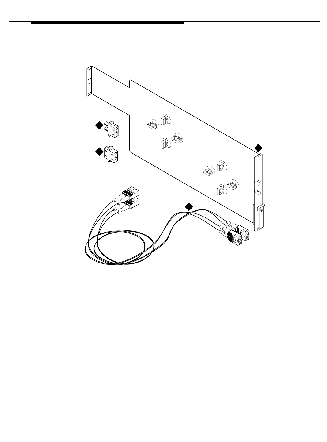
Complete this steps after the TN2305X/TN2306X circuit pack is installed.
1. Insert the connector into the top opening at the rear of the NAA1 circuit
pack. See Figure 2-2 on page 2-6.
2. Attach either the single mode (yellow) cable or multimode (orange) cable to
the connector.
3. Route the cable through the slot A in the faceplate.
4. Determine how much of the cable is needed to reach the ATM circuit pack.
5. Wrap the excess cable as shown in Figure 2-2 on page 2-6 and secure with
the clips.
6. Repeat these steps for each circuit pack used.
NOTE:
In Step 1, use the bottom opening at the rear of the NAA1 circuit
pack.
In Step 3, use slot B in the faceplate.
In Step 5, use the lower set of clips to secure the excess cable.
108424391
7. Insert the NAA1 circuit pack into slot 11 on the top row of the compact
modular cabinet.
!
CAUTION:
Do not attempt to put this circuit pack into any other slot as pin
damage may occur.
Issue 5 October 2002
2-5555-233-124
Page 40
Installing a DEFINITY Server ATM-CES
8. Route the cable(s) to the TN2305X/TN2306X circuit pack(s) and connect
them.
NOTE:
The loop formed by the cable connecting the two circuit packs must
have a minimum radius of 1 in. (2.54 cm). If not, adjust the cable or
move the circuit pack(s) to another location.
9. Connect the other equipment into the connector(s) at the rear of the NAA1
circuit pack.
A
B
A
B
ckdanaa1 LJK 021199
Figure 2-2. NAA1 Circuit Pack with Cables Attached
A
B
B
A
B
A
2-6 Issue 5 October 2002
555-233-124
Page 41

Installing a DEFINITY Server AT M -P N C
This chapter describes the procedures for installing a new Avaya MultiVantage
®
on a DEFINITY
■ Installing Equipmen t
■ Installing and Testing Network Synchronization
■ Setting Up ATM Network Duplication
■ Installing a WAN Spare Processor
Server ATM system. The process includes
Installing Equipment
If the ATM switch and interface circuit packs are already installed, then the actual
upgrade to ATM-PNC is done administratively in Chapter 5, ‘‘Administering
ATM-PNC and ATM-CES’’.
To prepare for a new DEFINITY Server ATM installation refer to the following:
■ DEFINITY Made Easy (online at URL: http://made-easy.avaya.com)
Review the reliability configurations for Avaya DEFINITY Server ATM (refer to
Figure 1-3 on page 1-10 through Figure 1-5 on page 1-12) and determine the
synchronization sources (DS1, E1, or ATM network).
Issue 5 October 2002 3-1555-233-124
Page 42

Installing a DEFINITY Server ATM-PNC
Slot restrictions for an ATM interface circuit packs are similar to expansion
interface circuit packs:
■ PPN: ATM interface circuit packs used for ATM-PNC must occupy the slots
labeled EXPANSION INTERFACE.
■ EPNs: ATM interface circuit packs used for ATM-PNC can occupy slot 1
(and 2, if duplicated) on carrier A, and also slot 2 (and 3, if duplicated) on
carrier B
Follow the steps in Table 3-1 to ensure that
■ the applicable equipment is installed correctly.
■ the customer’s configuration is properly recorded (use worksheet in
Appendix A, ‘‘Baselining the Customer’s Configuration’’).
Table 3-1. General installation process
√ Step Action Description
1. Install DEFINITY
Server
2. Install ATM switch(es)
or access
concentrators
3. Check the distances
from the ATM switch
to the DS1 timing
source
4. Install ATM interface
circuit pack
5. Route the fiber optic
cables between the
ATM switch and the
DEFINITY Server
PPN and EPNs.
6. Connect the fiber
optic cables
Refer to the appropriate installation book
See ‘‘DEFINITY Server configurations’’ on page 1-9 for
connection schematics.
Refer to your ATM switch’s quick reference guide. To get a
copy of the quick refere nce gu ide, go to th e Avaya web site
(http://www.avaya.com), clic k on Sup port, an d then fi nd the
page for your Avaya ATM solution.
Use the information in Table 3-3 on page 3-14 to deter mine
the maximum cable run lengths for the configuration for
more information.
Insert the TN2305/TN2306 circuit pack(s) into the
appropriate slot(s).
Follow the fiber pass-through procedure in the appropriate
installation book.
!
WARNING:
Be sure that the fiber optic cable is secured so that
the door of the DEFINITY Server does not pinch or
bend the cable.
Connect the fiber optic cables to the ATM switch.
NOTE:
If the installation uses the customer’s existing fiber,
you may need an ST-to-SC adapter (1 included in
Fiber Pass-Through Kit).
3-2 Issue 5 October 2002
Continued on next page
555-233-124
Page 43

Installing Equipment
Table 3-1. General installation process (Continued)
√ Step Action Description
7. Connect the fiber
optic cables to the
ATM interface circuit
packs
Connect fiber optic cable to the SC connector on the
faceplate of each TN2305/TN2306 circuit pack in the
DEFINITY Server PPN and EPN.
■ The TN2305/TN2306 circuit pack interface requires SC
connectors (see Note in Step 5).
■ Do not reuse existing fiber cabling with ST connectors
at both the DEFINITY Serve r and the ATM switch. This
requires an ST-to-SC adapter at both ends. It is better
to order the cable with the SC c on nec tors a t bo th ends.
8. Record configuration Record DEFINITY Server switch-to-ATM port (port
locations for each ATM circuit pack) in Table A-1 (in
Appendix A, ‘‘Baselining the Customer’s Configuration’’).
NOTE:
Read the MAC addresses fro m the A TM s witch (refer
to your ATM switch’s quick reference guide) and
record them in Table A-1.
9. Record fiber
connections
10. Install and test
synchronization
splitter, if required.
Record the fiber optic c ab le runs o n th e l igh tw av e i nte rfac e
(LIU) diagram (Figure A-1) in Appendix A, ‘‘Baselining the
Customer’s Configuration’’.
Follow the procedures for installing and testing the
synchronization splitter and the T1 or E1 timing source in
‘‘Installing and Testing Network Synchronization’’ on page
3-4.
Continued on next page
Issue 5 October 2002
3-3555-233-124
Page 44

Installing a DEFINITY Server ATM-PNC
Installing and Testing Network Synchronization
An Avaya MultiVantage on DEFINITY Server ATM-PNC requires network
synchronization for DS1 circuit packs not to slip relative to the LEC/IXC switches.
The ATM switch serves as the sync reference source for the DEFINITY Server.
The A TM switch, in turn, derives primary and secondary sync. To accomplish this,
the most common option is to use synchronization expanders (splitters).
Connections without synchronization splitters
In some configurations the ATM switches are traced to network clocks through
their SONET /SDH interfaces, not requiring any synchronization splitters.
However, the ATM switch could require a single splitter if only one of the sync
sources is derived from the network.
The ATM switches may obtain their network synchronization as follows:
■ The ATM switch gets its network timing reference from its
SONET/SDH/SDIT interface to that network.
■ Or if the customer wants to use a DS1 source for network synchronization
that also happens to be a DEFINITY Server switch trunk, then one sync
splitter is necessary to send a copy of that DS1 signal to the ATM switch.
The DS1 circuit pack is only an indirect timing reference for the DEFINITY
Server.
Connections needing synchronization splitters
If the ATM network does not provide a synchronization expander (splitter), then
the ATM configurations may require one that takes a DS1 T1 or E1 signal and
redirects it to the
■ ATM switch(es), depending on confi gur ati on and dupli ca tio n
■ DEFINITY Server through the DS1 circuit pack
This creates a single synchronization source.
Check the customer’s configuration carefully so that you can
■ Connect the hardware correctly during installation
■ Properly administer the synchronization plan later (Chapter 5,
‘‘Administering ATM-PNC and ATM-CES’’)
3-4 Issue 5 October 2002
555-233-124
Page 45

Installing and Testing Network Synchronization
This section covers the synchronization installation and test process.
■ Splitter descriptions—Describes the splitter’s inputs and outputs
■ Synchronization spl it ter connections—Connection diagrams for timing
connections through a DSU/CSU (Figure 3-6 on page 3-11) and an ICSU
(Figure 3-7 on page 3-12)
■ Verify the DS1 service—Checks for presence of the DS1 T1 or E1 timing
source and the general health of the DS1 circuit pack.
■ Installing and testing the splitter provides the following information
— Splitter port tests (401A/402A only)
— Installing a 400A T1 splitter
— Installing 401A, 402A, or 403A splitters
Installing and testing the synchronization splitter involves interrupting the DS1
signal provided by the service provider. Even though the DS1 circuit pack should
be down less than 5 minutes, before removing a working T1/E1 span, contact the
service provider. Failure to notify the T1/E1 service provider may result in:
— The service provider looping the T1/E1 span back to the subscriber.
— A span alarm being detected at the central office and the span being
taken out of service, sending an AIS (blue Alarm) to the DEFINITY
Server. The synchronization signal is necessary for testing
equipment and connections.
Splitter descriptions
Table 3-2 describes the 4 splitter models and their capabilities. The drawings
show the splitters and their connection points. Figure 3-5 on page 3-10 shows a
schematic of the 2 jumper sets and their connections for 401A, 402A, and 403A
sync splitters.
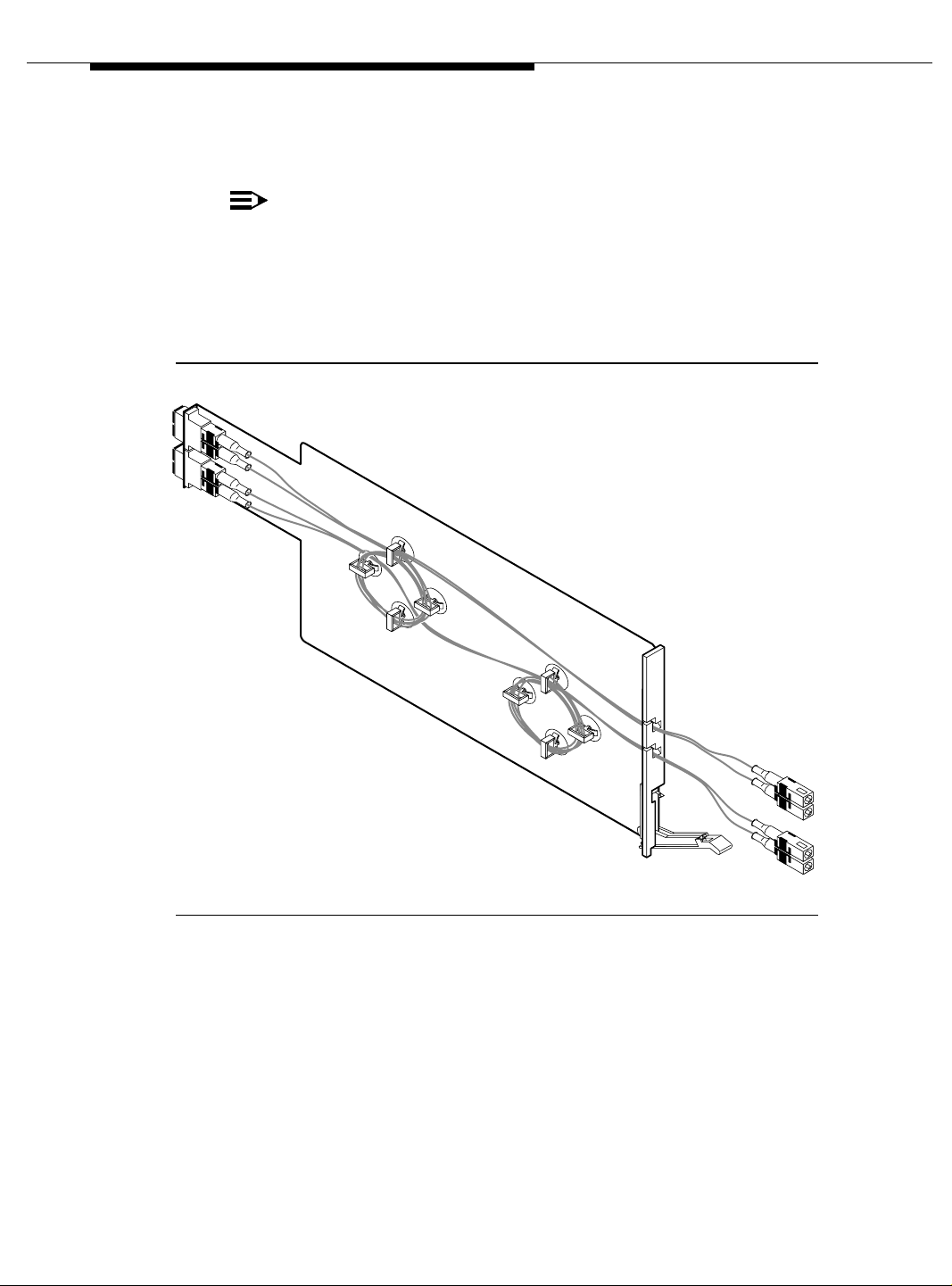
Table 3-2. Synchronization splitter models and attributes
Model T1/E1 Impedance Comcode Drawing Description/Application
400A T1 100 Ω 108217795 Figure 3-1 No ICSU capability
401A T1 100 Ω 108508078 Figure 3-2 Limited ICSU capability
402A E1 120 Ω 108508094 Figure 3-3
403A E1 75 Ω 108508102 Figure 3-4
Continued on next page
Issue 5 October 2002
3-5555-233-124
Page 46

Installing a DEFINITY Server ATM-PNC
3
4
J1
J2
1
crda400a LJK 071698
2
Figure Notes:
1. From network interface
2. Amphenol connection to
3. Timing output port (J1) to the ATM switch
4. Timing output port (J2) to the ATM switch
DEFINITY Server
1. Ports J1 and J2 provide identical DS1 timing sou rce signals to the A TM s witches. The
ATM switch can use two separate DS1 timing signals (one at a time from two
separate spans).
1
1
Figure 3-1. 400A synchronization splitter
3-6 Issue 5 October 2002
555-233-124
Page 47

Installing and Testing Network Synchronization
5
1
3
2
NETWORK
401A
108508078
H
O
0
0
1
P
S
C
N
Y
S
TO DEFINITY
ALARM
M
IT
L
1
T
R
E
T
crda401a KLC 020300
TO ATM SWITCH
4
5
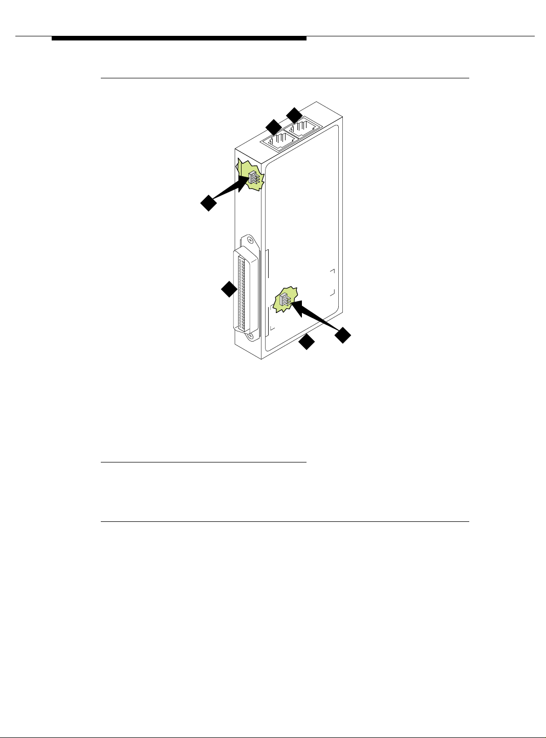
Figure Notes:
1. Amphenol connector to
DEFINITY Server
2. Network timing connection
1. Ports J1 and J2 provide identical DS1 timing source signals to the A TM s witches. The
ATM switch can use two separate DS1 timing signals (one at a time from two
separate spans).
3. Timing alarm lead connection
4. Timing output ports (RJ45) to ATM switch
1
5. Jumpers and capacitors (inside case). See
Figure 3-5 on page 3-10 for settings.
Figure 3-2. 401A synchronization splitter
Issue 5 October 2002
3-7555-233-124
Page 48
Installing a DEFINITY Server ATM-PNC
5
3
2
ALARM
NETWORK
402A
1
108508094
1
N
Y
1
S
TO DEFINITY
E
M
H
R
O
0
2
C
E
T
IT
L
P
S
crda402a KLC 020300
TO ATM SWITCH
4
5
Figure Notes:
1. Amphenol connector to
DEFINITY Server
2. Network timing connection
1. Ports J1 and J2 provide identical DS1 timing sou rce signals to the A TM s witches. The
ATM switch can use two separate DS1 timing signals (one at a time from two
separate spans).
3. Timing alarm lead connection
4. Timing output ports (RJ45) to ATM switch
1
5. Jumpers and capacitors (inside case). See
Figure 3-5 on page 3-10 for settings.
Figure 3-3. 402A synchronization splitter
3-8 Issue 5 October 2002
555-233-124
Page 49
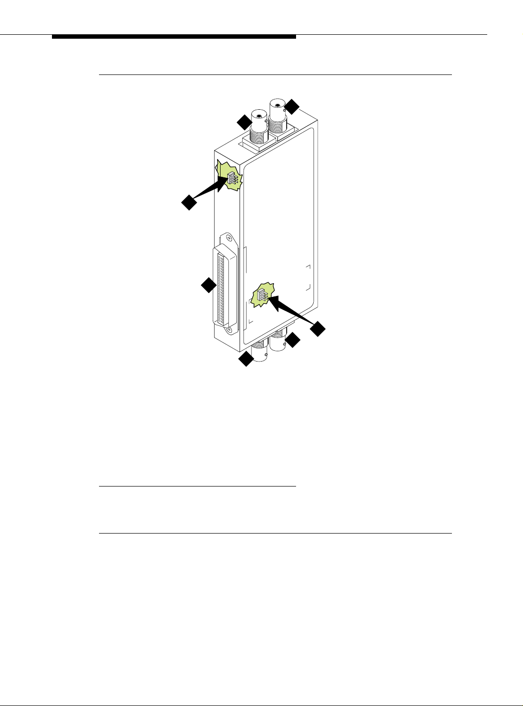
Installing and Testing Network Synchronization
4
6
5
X
T
K
R
X
R
O
W
T
E
N
403A
108508102
75 OHM E1
1
SYNC SPLITTER
TO DEFINITY
C
IT
W
S
M
TO AT
H
crda403a LJK 101501
6
3
2
Figure Notes:
1. Amphenol connector to DEFINITY
Server
2. Synchronization source (timing
output ports) to ATM switch
3. Synchronization sourc e (timing
output ports) to ATM switch
1
1
1. These are identical DS1 timing source signals to the ATM switches. The ATM switch
can use two separate DS1 timing signals (one at a time from two separate spans).
4. Network receive connection, BNC
connector
5. Network transmit connection, BNC
connector
6. Jumpers and capacitors (inside case).
See Figure 3-5 on page 3-10 for settings.
Figure 3-4. 403A synchronization splitter
Issue 5 October 2002
3-9555-233-124
Page 50

Installing a DEFINITY Server ATM-PNC
RX
TX
4
5
6
3
4
2
TX
1
NETWORK
3
2
ALARM
8
7
402A
108508094
120 OHM E1
1
5
5
6
3
4
2
TX
1
SYNC SPLITTER
TO DEFINITY
TO ATM SWITCH
6
Figure Notes:
1. Amphenol connection to DEFINITY
Server switch
2. Row of capacitors
3. Jumpers for incoming network
connections
4. Incoming network transmit and
receive connections
5. Jumper 1-2 = true ground
Jumper 5-6 = shield grounded
Jumper 3 = TX cable ground
Jumper 4 = RX cable ground
Default connections = 1-2, 3-5
Figure 3-5. Jumper settings (401A/402A/403A)
3-10 Issue 5 October 2002
jpda40xa LJK 101501
6. True ground
7. Cable shield grounded
8. Jumper 1-2 = true ground
Jumper 5-6 = shield grounded
Jumper 3 = ATM switch A TX cable ground
Jumper 4 = ATM switch B TX cable ground
Default connections = 3-5, 4-6
9. Out put jumpers
10. Timing output to ATM switch A
11. Timing output to ATM switch B
555-233-124
Page 51

Installing and Testing Network Synchronization
Synchronization splitter connections
The splitter connects to a timing source. Figure 3-6 shows the synchronization
connections through a DSU/CSU (400A), and Figure 3-7 on page 3-12 shows the
synchronization connections through an ICSU (400A). Figure 3-8 on page 3-13
shows the synchronization connections directly to the timing source (401A, 402A,
403A).
1
2
8 9
7
6
5
4
3
cydaatm2 LJK 020100
Figure Notes:
1. Public Switched T elephone Network
(PSTN)
2. Main distribution frame (MDF) or
smart jack.
3. Channel service unit (CSU)
4. H600-307-GR2 cable
5. 400A T1 (100 Ω) splitter connects to
the DEFINITY Server
6. H600-383 quad cable from sync splitter to ATM
switch A
7. H600-383 quad cable from sync splitter to ATM
switch B (critical reliability/ATM network
duplication)
8. Avaya ATM switch A
9. A vaya A TM switch B (critical reliability/A TM network
duplication)
Figure 3-6. Synchronization connections through an external DSU/CSU
(400A)
Issue 5 October 2002
3-11555-233-124
Page 52
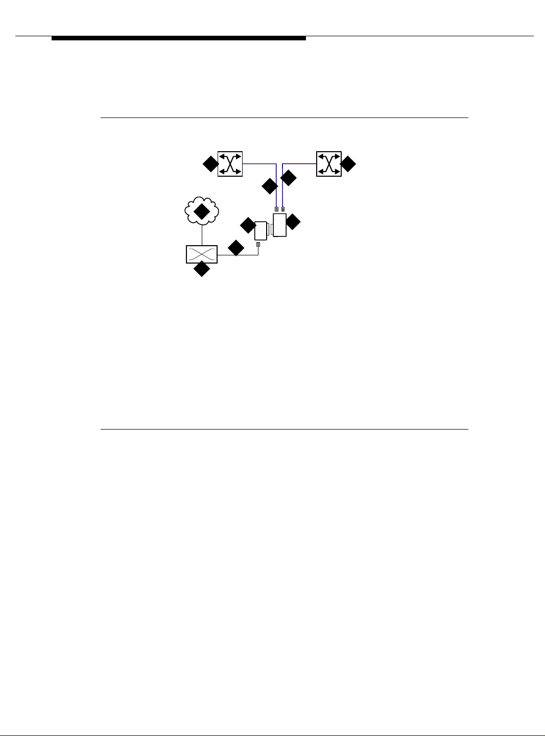
Installing a DEFINITY Server ATM-PNC
Use the information in Table 3-3 on page 3-14 to determine the maximum cable
run lengths for the configuration.
7 8
6
5
1
9
3
2
4
cydaatm1 LJK 020100
Figure Notes:
1. Public Switched T elephone Network
(PSTN)
2. Main Distribution Frame (MDF) or
smart jack
3. H600-383 quad cable
4. 400A T1 (100 Ω) spli tter connected
to DEFINITY Server
5. H600-383 quad cable from sync splitter to ATM
switch A
6. H600-383 quad cable from sync splitter to
duplicated ATM switch B (critical reliability)
7. Avaya ATM switch A
8. Avaya ATM switch B (critical reliability
network duplication)
9. ICSU
Figure 3-7. Synchronization connections through an ICSU (400A)
/ATM
3-12 Issue 5 October 2002
555-233-124
Page 53
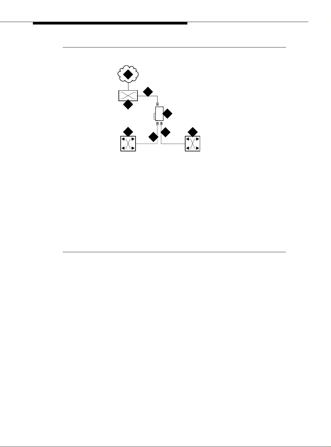
Installing and Testing Network Synchronization
1
3
2
4
7
6
5
cydaatm3 KLC 020200
8
Figure Notes:
1. Public switched telephone network
(PSTN)
2. Main distribution frame (MDF) or
smart jack
3. H600-383 quad cable
4. 401A T1 (100 Ω) splitter,
402A E1 (120 Ω) splitter, or
403A E1 (75 Ω) splitter connected
to DEFINITY Server
5. H600-383 quad cable from sync splitter to ATM
switch A
6. H600-383 quad cable from sync splitter to
duplicated ATM switch B (critical reliability
network duplication)
7. Avaya ATM switch A
8. Avaya ATM switch B (critical reliability
network duplication)
Figure 3-8. Synchronization connections directly to timing source
(401A/402A/403A)
/ATM
/ATM
Issue 5 October 2002
3-13555-233-124
Page 54

Installing a DEFINITY Server ATM-PNC
Use the information in Table 3-3 to determine the maximum cable run lengths for
the configuration.
Table 3-3. Maximum cable lengths
Splitter Used in Cable
400A
T1
100 Ω
401A
T1
100 Ω
402A
E1
120 Ω
403A
E1
North America
(USA and Canada)
North America
(USA and Canada)
See T able 3-4 on page
3-15
See T able 3-4 on page
3-15
H600-383
shielded
twisted pair
H600-383
shielded
twisted pair
120-Ω
shielded
twisted pair
75-Ω
coaxial
1
1
Maximum distance from
splitter to ATM switch
130 feet
43 meters
1310 feet
2
393 meters
1000 feet
2
305 meters
1000 feet
2
305 meters
75 Ω
Continued on next page
1. Must have RJ45 connectors on each end.
2. The loss allowed in the cable is 6 dB. Typical cables have losses of 0.6 dB/100 ft;
hence, 1000 feet may be considered a typical distance. Distance varies if cables with
different losses are used.
3-14 Issue 5 October 2002
555-233-124
Page 55

Installing and Testing Network Synchronization
Table 3-4 lists the splitter model(s) applicable to specific countries.
Table 3-4. Country-specific splitter applications
Country
Argentina Y
Australia Y
Austria Y Y
Bahrain Y Y
Belgium Y Y
Brazil Y
Canada Y
China Y
Columbia Y
Denmark Y Y
400A/401A
T1
100 Ω
Splitter model
402A
E1
120 Ω
403A
E1
75 Ω
Egypt Y Y
Finland Y Y
France Y Y
Germany Y Y
Hong Kong Y
India Y Y
Indonesia Y Y
Ireland Y Y
Italy Y Y
1
Japan
Korea Y Y
Luxembourg Y Y
Malaysia Y Y
Mexico Y
Netherlands Y Y
New Zealand Y Y
Norway Y Y
Continued on next page
Issue 5 October 2002
3-15555-233-124
Page 56

Installing a DEFINITY Server ATM-PNC
Table 3-4. Country-specific splitter applications (Continued)
Country
Philippines Y Y
Poland Y Y
Portugal Y Y
Russia Y Y
Saudi Arabia Y Y
Singapore Y
South Africa Y Y
Spain Y Y
Sri Lanka Y Y
Sweden Y Y
Switzerland Y Y
400A/401A
T1
100 Ω
Splitter model
402A
E1
120 Ω
403A
E1
75 Ω
Taiwan Y Y
Ukraine Y Y
UAE Y Y
UK Y Y
USA Y
Uzbekistan Y Y
Vietnam Y Y
Continued on next page
1. Japan uses both 75-Ω and 120-Ω T1; 402A and 403A sync
splitters will also work with T1s.
3-16 Issue 5 October 2002
555-233-124
Page 57

Installing and Testing Network Synchronization
Verify the DS1 service
To verify the DS1 service, use the procedure in Table 3-5. Have the ATM switch
installer verify the synchronizat ion source.
Table 3-5. T1 or E1 service verification procedure
√ Step Action Command Description
1. Check timing
signal
2. Test the DS1
circuit pack
3. Run error report list
4. Identify active
synchronization
source
test board
UUCSS
measurements
ds1
summary
status
synchronization
UUCSS
Check that the GREEN STATUS 3 LED on the
designated DS1 circuit pack is on steady.
Test the designated DS1 board.
If any one of Test 138 through 145 fails, follow the
repair procedures listed in Maintenance for Avaya
MultiVantage and DEFINITY Server R.
Verify that the report is free of errors.
Table 3-6 on page 3-18 to help interpret the
See
report.
Verify that the designated DS1 circuit pack is the active
sync source.
Note: The DS1circuit pack is not the sync source; it
simply shows where the sync splitter is connected.
Continued on next page
Issue 5 October 2002
3-17555-233-124
Page 58

Installing a DEFINITY Server ATM-PNC
Table 3-6. Interpretation of the list measurements report
Displayed
Field Function Indication
Test:
cpe-loopback
3-in-24 stress
test pattern
-jack
Synchronized = Y
= N
Bit Error
Count
Cumulative
detected
errors
The loopback jack test is active
The DS1 circuit pack is synchronized to the looped
3-in-24 pattern and is counting the bit errors detected
in the pattern until the test is ended.
Retry the test:
1. Stop the test (test ds1-loop UUCSS end
cpe-loopback-jack-test).
2. Restart the test (test ds1-loop UUCSS
cpe-loopback-jack-test-begin)
3. Repeat Steps 1 and 2 a maximum of 5 times, as
necessary.
If the circuit pack never synchronizes, it is possibly
due to intermittent connections or a broken wire in a
receive or transmit wire pair.
0 indicates that there are no wiring problems.
A count that sits at 65535 or continues to increment by
several hundred to several thousand errors with each
subsequent list measurements command indicates
3-18 Issue 5 October 2002
■ Intermittent or corroded connections
■ Severe crosstalk
■ Impedance imbalances between the two
conductors of the receive or the transmit pairs.
1. Replace wiring, if ne cessary.
2. Note whether the Extended Super Frame (ESF)
error and performance counters summaries
(errored seconds, bursty errored seconds, and so
forth) also increment. Although these counters are
not used with the loopback jack test, they do
increment as errors occur.
Continued on next page
555-233-124
Page 59

Installing and Testing Network Synchronization
Installing and testing the splitter
The splitter must be installed and tested before the upgrade and cutover. The
purpose of testing the splitter is to
■ Prove that there is enough signal level for the cable length to the ATM
switch:
— up to 130 ft. (39.65 m) for 400A
— within the standard 6 dB allowable loss for 401A, 402A, and 403A
(see Table 3-3 on page 3-14)
■ Ensure that the DS 1 circ uit pa ck fun ction s prop erly wh ile r eceivi ng th e DS1
signal level output from the splitter (Ports J1 and J2 unterminated).
Table 3-7 shows the configurations of the test cable and ports on the sync splitter.
Table 3-7. Cable and port configurations for splitter tests
To test Description
Port J1 Insert an opening plug into port J2
Port J2 Insert an opening plug into port J1
Maximum output of the splitter
to the DS1 circuit pack
Insert an opening plug into both ports J1 and J2
Splitter port tests (401A/402A only)
NOTE:
The standard RJ45-to-Bantam test cable does not work with the 403A.
To test the splitter ports J1 or J2, use the procedures in T able 3-8, usin g t h e RJ 45
to Bantam Test cable from the 1541CC cable kit.
Table 3-8. Testing the splitter ports
√ Step Action Command Description
1. Terminate one
or more ports
2. Connect to
DS1 circuit
pack
Plug the RJ45 (modular) end of the DS1 test cable
into the jack (J1 or J2) you wish to test on the
splitter.
Plug the Bantam Plug end (plug with the black
band) of the DS1 test cable into the Equipment-In
(EI) jack on the DS1 circuit pack faceplate.
Continued on next page
Continued on next page
Issue 5 October 2002
3-19555-233-124
Page 60

Installing a DEFINITY Server ATM-PNC
Table 3-8. Testing the splitter ports (Continued)
√ Step Action Command Description
3. Test
DS1circuit
pack
test board
UUCSS
Wait 30 seconds, then test the circuit pack.
If any tests fail, wait 5 minutes and test the DS1
circuit pack again.
4. Replace
splitter if
necessary
5. Escalate if
necessary
If any test still fails, replace the splitter and retest.
If the test still fails, escalate to Tier 3 Support.
Continued on next page
Installing a 400A T1 splitter
NOTE:
Make sure you are connected to the network before connecting to the
DEFINITY Server.
Once the sync splitter passes the DS1 span tests, it can be installed and tested in
place. The 400A sync splitter can be either
■ Connected through an ICSU
■ Connected through a DSU/CSU.
NOTE:
If using a TN464F/TN767E v18 or earlier, you must reseat the circuit pack
each time the splitter is plugged on.
3-20 Issue 5 October 2002
555-233-124
Page 61

Installing and Testing Network Synchronization
Connected through an ICSU. Use the procedures in Table 3-9 to install the
splitter between an ICSU and a DS1 circuit pack.
Table 3-9. Installing the splitter through an ICSU
√ Step Action Command Description
1. Disable
synchronization
switch
2. Busyout DS1
circuit pack
3. Remove cable
from DS1 circuit
pack
4. Remove ICSU Remove the ICSU from the designated DS1 circuit pack’s
5. Attach splitter Plug the splitter into the same connector just vacated by
6. Attach ICSU Plug the ICSU into the connector on the splitter.
disable
synchronization
-switch
busyout board
UUCSS
Prevent the system from switching synchronization
sources.
Busyout the designated DS1circuit pack.
Remove the existing H600-307 cable from the backplane
slot corresponding to the designated DS1 circuit pack.
amphenol connector.
Re-use the existing cable attached to the ICSU.
the ICSU.
7. Reconnect
cable
8. Check
connections
9. Secure splitter Secure the splitter to the carrier using the 4C retainer from
10. Secure ICSU Secure the ICSU to the splitter with a long cable tie.
11. Terminate the
splitter ports J1
and J2
12. Check DS1
Status 3 LED
13. Test the DS1
circuit pack
14. Clear the error
events counters
test board
UUCSS
clear
measurements
ds1
esf-error-events
UUCSS
Connect the H600-307 cable to the amphenol connector
on the ICSU.
Check that all Amphenol connections are good.
the ICSU.
Insert a modular RJ45 plug in both ports J1 and J2. Do not
connect port J1 to port J2, but leave the other end of both
cords free. The modular RJ45 plug acts as an opening plug
and removes the 100-Ω termination from port J1 and J2 on
the splitter.
After about 20 seconds the LEDs on the DS1 circuit pack
should go out, leaving only the GREEN STATUS 3 LED on.
Test the circuit pack.
If any one of Tests 138 - 145 fails, follow the repair
procedures listed in Maintenance for Avaya MultiVantage
and DEFINITY Server R
Clear the error events counter.
Continued on next page
Issue 5 October 2002
3-21555-233-124
Page 62

Installing a DEFINITY Server ATM-PNC
Table 3-9. Installing the splitter through an ICSU (Continued)
√ Step Action Command Description
15. Run report list
measurements
ds1 summary
UUCSS
16. Replace
connections
17. Test the ICSU Depending on the ICSU model, go to the appropriate
Wait 15 minutes before entering the command.
If the DS1 circuit pack is not error-free, refer to
‘‘Troubleshooting synchronization (400A only)’’ on page
.
6-31
After testing is complete, remove the modular RJ45
opening plugs from port J1 and J2 of the splitter, and
reconnect the cables to the port(s).
section:
■ Testing the 120A ICSU (Table 3-10)
■ Testing the 120A 2 ICSU (Table 3-11 on page 3-23)
Test the 120A ICSU with either a 700A DS1 CPE loopback jack or a 103A block.
Use the procedure in Table 3-10 to test a splitter connected through an ICSU.
Continued on next page
Table 3-10. The 120A ICSU test procedure
√ Step Action Command Description
1. Connect 103A
block if
necessary
2. Test the DS1
circuit pack
3. Clear the error
events
counters
4. Run report list measurements
test board UUCSS Test the DS1 circuit pack.
clear
measurements
ds1
esf-error-events
UUCSS
ds1 summary
UUCSS
If the 700A DS1 CPE Loopback Jack is not installed or if
the ICSU is not a 120A:
■ Connect a 103A block at the Smart Jack end of the
H600-383 cable.
■ On the 103A block, strap pin1 to pin 3 and pin 2 to
pin 4, which provides a loopback to the ICSU.
If any one of Tests 138 through 145 fails, follow the repair
procedures listed in Maintenance for Avaya MultiVantage
and DEFINITY Server R
Clear the error events counters.
Wait 15 minutes before entering the command.
To interpret the results, refer to Table 3-6 on page 3-18.
If the DS1 circuit pack is not error-free, refer to
‘‘Troubleshooting synchronization (400A only)’’ on page
6-31.
1
3-22 Issue 5 October 2002
Continued on next page
555-233-124
Page 63

Installing and Testing Network Synchronization
Table 3-10. The 120A ICSU test procedure (Continued)
√ Step Action Command Description
5. Remove the
103A block
Reconnect the
6.
cable
Remove the 103A block from Step 1.
Connect the H600-383 cable to the smart jack or dumb
block.
Continued on next page
1. For more information about Smart Jack CPE Testing, see Maintenance for Avaya MultiVantage
DEFINITY Server R, Chapter 6, “DS1 CPE Loopback Jack Installation and Operations Instructions.”
Use the procedures in Table 3-11 to test the 120A ICSU with the 700A DS1 CPE
loopback jack.
Table 3-11. Testing the 120A 2 ICSU
√ Step Action Command Description
1. Busyout the
DS1 circuit pack
2. Start the CPE
loopback test
3. Terminate the
test
4. Release the
DS1 circuit pack
5. Reassign
synchronization
busyout board
UUCSS
test ds1-loop
UUCSS
cpe-loopbackjack-test-begin
test ds1-loop
UUCSS
end-loopback/
span-test
release board
UUCSS
change
synchronization
Busyout the DS1 circuit pack.
Start the CPE loopback test.
■ I f the test passes, the splitter is functioning
properly; go to Step 3.
■ If the test fails, follow the procedures in
‘‘Troubleshooting synchronization (400A only)’’ on
page 6-31.
Terminate the test .
Release the DS1 circuit pack .
Reassign sync to the designated DS1 circuit pack .
Continued on next page
Issue 5 October 2002
3-23555-233-124
Page 64

Installing a DEFINITY Server ATM-PNC
Connected through a DSU/CSU. Before connecting any of the timing hardware,
ensure that the DSU/CSU is configured to report loss of signal alarms.
If using a 316X CSU connected to a T1 facility and used as the DEFINITY Server
synchronization source, verify or change the 316X settings (options) to ensure
that it sends an AIS blue alarm to the DEFINITY Server DS1 circuit pack or to the
ATM switch whenever a network LOS (loss of signal) occurs. Upon receiving a
LOS, the DEFINITY Server or ATM switch transfers to its backup synchronization
source.
To configure the 316X CSU to send an AIS blue alarm, use the procedures in
Table 3-12.
Table 3-12. Configuring the 316X CSU to send AIS blue alarm
√ Step Action Description
1. Configure CSU At the 316X CSU press the double-up arrow
2. Go through the
readout steps
Press the button under “Cnfig.”
3. Continue Press the button under “Activ.”
4. Continue Press the button under “Edit.”
5. Continue Press the right arrow until “GEN” displays.
6. Continue Press the button under “GEN.”
7. Continue Press F1 (“Next”) until “Gen Yellow Alarm” displays. ( This
option defaults as enabled.)
8. Continue Press the button under “Disabled.”
9. Continue Press the double-up arrow.
Save Option displays when “Enabled” changes to
“Disabled.”
10. Save settings Press the button under the word “Yes” at the “Save
Options Yes or No” prompt. Otherwise press F1 twice.
1 1. Save options Press the button under “Activ” when asked where to save
the options.
Command Complete displays.
12. Return to default
screen
13. Install the splitter
The CSU times out to its default ESF CSU Operational
screen or set it there by pressing the double-up arrow
once and then pressing F1 twice.
Go to Table 3-13 on page 3-25 to install the splitter.
3-24 Issue 5 October 2002
Continued on next page
555-233-124
Page 65

Installing and Testing Network Synchronization
NOTE:
All four faceplate status LEDs on the DS1 circuit pack are dark (not lit) when
using an external CSU or DSU/CSU. The STATUS LEDs on the DS1 circuit
pack are only functional with a 120A ICSU.
To install a 400A sync splitter between a CSU or DSU/CSU and a DS1 circuit
pack, follow the procedures listed in Table 3-13.
Table 3-13. Splitter installation to DS1
√ Step Action Command Description
1. Disable
synchronization
switch
2. Busyout DS1
circuit pack
3. Remove cable
from DS1
circuit pack
4. Attach the
splitter
5. Reconnect the
cable
6. Secure the
splitter
7. Check
connections
8. Release DS1
circuit pack
9. Test the splitter Use the procedure in ‘‘Splitter port tests
disable
synchronization
-switch
busyout board
UUCSS
release board
UUCSS
Prevent the system from switchin g
synchronization sources.
Busyout the designated DS1 circuit pack.
Remove the H600-3 07 cable f rom the amp henol
connector located on rear of the DS1 circuit
pack.
Plug the splitter into the same connector just
vacated by the H600-307 cable.
Plug the H600-307 cable into the connector on
the splitter.
Secure the splitter to the carrier using the large
mounting strap remov ed from a fi ber t ransce iver.
Check that all Amphenol connections are
secure.
Restore the designated DS1 circuit pack to
service.
(401A/402A only)’’ on page 3-19.
■ Before testing the splitter, insert a modular
RJ45 plug into jack J1 and jack J2.
NOTE:
Do not connect port J1 to port J2. Leave
the other end of both cord s fre e, b ec aus e
the modular RJ45 plug acts as a opening
plug and removes the 100-Ω terminatio n
from J1 and J2 ports.
■ After testing is complete, remove the
opening plugs from J1 and J2.
Continued on next page
Issue 5 October 2002
3-25555-233-124
Page 66

Installing a DEFINITY Server ATM-PNC
Table 3-13. Splitter installation to DS1 (Continued)
√ Step Action Command Description
10. Check
DSU/CSU
LEDs
11. Check for CSU
alarms
After about 20 s, all the ala rm LEDs on th e 316X
CSU or DSU/CSU should go out.
If this is the case, perform steps 11 through 12.
Otherwise, go to step 13.
Verify that no alar ms are against the CSU (the
OK, SIG, SIG LEDs are lit).
12. Test the circuit
pack
13. Run error
report
14. DTE and RLB
loopback tests
(new
installations)
test board
UUCSS
list
measurements
ds1 summary
UUCSS
Verify that the DS1 circuit pack passes Tests
138 through 145. If these tes ts pass and t his is a
new installation, go to Step 14.
If any one of Test 138 through 145 fails, follow
the repair procedures listed in Maintenance for
Avaya MultiVantage and DEFINITY Server R.
After clearing all errors, retest the circuit pack.
Wait 15 minute s. Chec k the error report and
verify that the DS1 circuit pack is free of any
errors.
To interpret the periodic list measurements
report.
Perform both DTE and RL B loo pb ack tes t at the
316X CSU or DSU/CSU to verify that the DS1
board can successfully transmit and receive a
DS1 signal through the splitter to the 316X and
back to the DS1 board.
Go to the ‘‘DTE loopback procedure’’ on page
3-27 and ‘‘RLB loopback procedure’’ on page
3-28
Continued on next page
3-26 Issue 5 October 2002
555-233-124
Page 67

Installing and Testing Network Synchronization
DTE loopback procedure. To start the Data Terminal Equipment (DTE) loopback
at the 316X CSU or DSU/CSU, use the procedures in Table 3- 14.
Table 3-14. DTE loopback testing for the 316X DSU/CSU
√ Step Action Command Description
1. Begin the
loopback test
2. Go through the
readout steps
3. Continue Press the button under “Lpbk.”
4. Continue Press the button under “DLB.”
Press the double-up arrow button.
Press the button under “Test.”
Test Started displays. Th e 3 16X is no w in
DTE loopback.
5. Test the circuit
pack
6. Run error
report
7. Terminate the
DTE loopback
test
8. Go through the
readout steps
test board
UUCSS
list
measurements
ds1 summary
UUCSS
At the DEFINITY Server management terminal.
If any one of Test 138 through 145 fails, follow
the repair procedures listed in Maintenance for
Avaya MultiVantage and DEFINITY Server R.
Wait 15 minutes and verify that the DS1 circuit
pack is free of any errors.
Use Table 3-6 on page 3-18 to interpret the
periodic list measurements report.
Press the double-up arrow button.
Press the button under “test.”
9. Continue Press the button under “lpbk.”
10. Continue Press the button under “abort.”
11. Continue Press the button under “all.”
12. Continue test
procedure
If all tests pass, and the splitter, cabling, and
316X CSU or DSU/CSU are working properly,
go to the ‘‘RLB loopback procedure’’ on page
3-28.
Continued on next page
Issue 5 October 2002
3-27555-233-124
Page 68

Installing a DEFINITY Server ATM-PNC
RLB loopback procedure . To start the RLB loopback testing at the 316X CSU or
DSU/CSU, use the procedures in Table 3-15.
Table 3-15. RLB loopback testing for the 316X DSU/CSU
√ Step Action Command Description
1. Start the test. Press the double-up arrow button.
2. Go through the
readout steps
3. Continue Press the button under “Lpbk.”
4. Continue Press the button under “RLB.”
Press the button under “Test.”
Test Started displays. The 316X is now in
RLB loopback.
5. Test the circuit
pack
6. Run error
report
7. Terminate the
RLB loopback
test
8. Go through the
readout steps
9. Continue Press the button under “lpbk.”
10. Continue Press the button under “abort.”
11. Continue Press the button under “all.”
12. Return
DSU/CSU t o
service
13. Go through the
readout steps
14. Continue Press the button under “Cntrl.”
test board
UUCSS
list
measurements
ds1 summary
UUCSS
If any one of Test 138 through 145 fails, follow
the repair procedures listed in Maintenance for
Avaya MultiVantage and DEFINITY Serve r R.
Wait 15 minute, then verify that the DS1 circuit
pack is free of any errors.
Use Table 3-6 on page 3-18 to interpret the
periodic list measurements report.
Press the double-up arrow button.
Press the button under “test.”
If all tests pass, and the splitter, cabling, and
316X CSU or DSU/CSU are working properly.
Press the double-up arrow.
Press the right-arrow button until “Cntrl”
displays.
15. Continue Press the button under “LED.”
16. Continue Press the button under the word PRT1, PRT2,
3-28 Issue 5 October 2002
PRT3 or PRT4 as required.
Continued on next page
555-233-124
Page 69

Installing and Testing Network Synchronization
Table 3-15. RLB loopback testing for the 316X DSU/CSU (Continued)
√ Step Action Command Description
17. Verify that the
DSU/CSU is in
normal
operating
mode.
Press the double-u p arrow once, th en press the
F1 button twice.
displays.
ESF CSU OPERATIONAL
Installing 401A, 402A, or 403A splitters
To install a 401A, 402A, or 403A sync splitter between the network and a DS1
circuit pack, follow the procedures listed in Table 3-16.
Table 3-16. Splitter installation to DS1 (401A/402A/403A)
Continued on next page
√ Step Action Command Description
1. Disable
synchronization
switch
2. Busyout DS1
circuit pack
3. Administer
sync splitter
4. Remove cable
from DS1
circuit pack
5. Attach the
splitter
6. Reconnect the
cable
7. Secure the
splitter
8. Check
connection
9. Reseat DS1
circuit pack
disable
synchronization
-switch
busyout board
UUCSS
change DS1
UUCSS
Prevent the system from switc hin g
synchronization sources.
Busyout the designated DS1 circuit pack.
Administer the sync splitter.
For T1, set the
to integrated (see Screen 3-1 on page 3-31).
For E1, set the
y (see Screen 3-2 on page 3-31).
Remove the cable fr om the amp henol con nector
located on rear of the DS1 circuit pack.
Plug the splitter into the same connector just
vacated by the cable.
Plug the cable into the connector on the splitter.
Secure the splitter to the carrier using the large
mounting strap remov ed from a fi ber t ransce iver.
Check that the Amphenol connection is secure.
Release the clip holding the DS1 circuit pack,
pull out slightly, close clip.
Near-end CSU Type: field
E1 Sync-Splitter? field to
Continued on next page
Issue 5 October 2002
3-29555-233-124
Page 70

Installing a DEFINITY Server ATM-PNC
Table 3-16. Splitter installation to DS1 (Continued)(401A/402A/403A) (Continued)
√ Step Action Command Description
10. Release DS1
circuit pack
release board
UUCSS
Restore the designated DS1 circuit pack to
service.
11. Test the splitter Use the procedure in ‘‘Splitter port tests
(401A/402A only)’’ on page 3-19.
■ Before testing the splitter, insert a modular
RJ45 plug into jack J1 and jack J2
(401A/402A only).
NOTE:
Do not connect port J1 to port J2. Leave
the other end of both cord s fre e, b ec aus e
the modular RJ45 plug acts as a opening
plug and removes the 100-Ω termination
from J1 and J2 ports.
The standard RJ45-to-Bantam test cable
does not work with the 403A. You need a
coax-to-Bantam cable or an adapter for
the RJ45 connector.
12. Check the 7
DS1 LEDs
13. Test the circuit
pack
14. Run error
report
test board
UUCSS
list
measurements
ds1 summary
UUCSS
■ After testing is complete, remove the
opening plugs from J1 and J2.
After about 20 s, all th e alarm LEDs on the DS1
go out and the status 3 LED is steady green.
If this is the case, con tinue. If not, foll ow the DS1
span test procedures in the Maintenance for
Avaya MultiVantage and DEFINITY Serve r R.
Verify that the DS1 circuit pack passes Tests
138 through 146 and 1227. If these tests pass
and this is a new installation, continue.
If any one of Test 138 through 146 fails, follow
the repair procedures in Maintenance for Avaya
MultiVantage and DEFINITY Server R.
After clearing all errors, retest the circuit pack.
Wait 15 minute s. Chec k the error report and
verify that the DS1 circuit pack is free of any
To interpret the periodic list measurements
report, refer to
Continued on next page
3-30 Issue 5 October 2002
555-233-124
Page 71

Installing and Testing Network Synchronization
add ds1 b10 Page 1 of 2
Location: 01B10 Name: xxxxxxxxxxxxxxx
Bit Rate: 1.544 Line Coding: b8zs
Signaling Mode: isdn-pri
Connect: line-side
Interface Companding: mulaw CRC? n
Idle Code: 11111111
Slip Detection? n Near-end CSU Type: integrated
DS1 CIRCUIT PACK
Country Protocol: 1
Protocol Version: a
DCP/Analog Bearer Capability: 3.1kHz
Alarm When PRI Endpoint Detached? y
Screen 3-1. DS1 circuit pack—T1
add ds1 b10 Page 1 of 2
Location: 01B10 Name: xxxxxxxxxxxxxxx
Bit Rate: 2.048 Line Coding: hdb3
Signaling Mode: isdn-pri
Connect: line-side
Interface Companding: alaw CRC? n
Idle Code: 11111111
DS1 CIRCUIT PACK
Country Protocol: 2
Protocol Version: a
DCP/Analog Bearer Capability: 3.1kHz
Slip Detection? n Near-end CSU Type: other
E1 Sync-Splitter? y Alarm When PRI Endpoint Detached? y
Screen 3-2. DS1 circuit pack—E1
Issue 5 October 2002
3-31555-233-124
Page 72

Installing a DEFINITY Server ATM-PNC
Setting Up ATM Network Duplication
ATM-PNC configurations without duplicated SPEs can be supported with
duplicated EPN connectivity to other points on an ATM network, or ATM network
duplication. These points can be on separate ATM switches, the same ATM
switch, or directly connected to an ATM-WAN.
With respect to port network connectivity, there is no difference in performance
between ATM network duplication and critical reliability. ATM network duplication
configurations require
■ A simplex SPE complex in the PPN
■ Duplicate connectivity over ATM to all PNs
■ Duplicate ATM interfaces in each EPN
■ Duplicate Tone-Clock boards in each EPN.
An ATM network duplication configuration can be the result of
■ A new installation
■ An upgrade from a standard reliability system
The EPN configuration for ATM network duplication is the same as for an EPN
equipped for ATM critical reliability (Figure 3-9 on page 3-33).
3-32 Issue 5 October 2002
555-233-124
Page 73

Setting Up ATM Network Duplication
1
8
4
2
3
cydasmpx KLC 032502
Figure Notes
1. DEFINITY Server PPN1
2. Fiber connecting ATM-EI A to ATM switch A
3. Fiber connecting ATM-EI B to ATM switch B
4. Avaya ATM switch A
5. Avaya ATM switch B
6
5
7
10
6. Fiber connecting ATM switch A to EPNs
7. Fiber connecting ATM switch B to EPNs
8. DEFINITY Server EPN2
9. DEFINITY Server PPN2
10. DEFINITY Server EPN3
9
7
Figure 3-9. EPN configuration with ATM network duplication
Issue 5 October 2002
3-33555-233-124
Page 74

Installing a DEFINITY Server ATM-PNC
Network duplication administration
The procedure to administer ATM network duplication (Table 3-17) assumes that
customers with:
■ High reliability (duplex SPE complexes) and who desire greater reliability
would migrate to critical reliability configurations
■ Critical reliability conf igurations would not migrate to ATM network
duplication
NOTE:
The screens follow the table and reflect what displays on an R10r platform
using a SAT. Your screen interface and page numbers may differ.
Table 3-17. Network duplication administration procedure
√ Step Action Command Description
1. Check that
feature is turned
on
2. Add hardware
3. Add ATM B-PNC
address
4. Enable
duplication
display
system-parameters
customer-options
change atm-pnc
number
change
system-parameters
duplication
Ensure that the PNC Duplication? field on the
customer options screen is y (
page 3-35). This field is controlled by the
License File.
■ Insert a second TN2305/TN2306 ATM
Interface circuit pack in slot in the B-position
port carrier in each EPN or D-position carrier
in EPNs configured for 2 port networks.
■ Add a TN2182 tone-clock circuit pack in the
slot labeled Tone-Clock. Add it to the A-, B-,
D- and E-position carriers in EPNs
configured for 2 port networks.
Bring up the ATM PNC screen (number is the
connection number assigned to each PNC being
administered).
Add in the B-PNC ATM address information in
the right-hand column of the screen (
on page 3-35
Change the Enable Operation of PNC
Duplication? field on the Duplication-Related
System Parameters screen to y (
page 3-35).
Screen 3-3 on
Screen 3-4
).
Screen 3-5 on
3-34 Issue 5 October 2002
NOTE:
The Enable Operation of Spe
Duplication? field must remain n.
Continued on next page
555-233-124
Page 75

Setting Up ATM Network Duplication
change system-parameters customer-options Page 3 of 6
OPTIONAL FEATURES
Hospitality (Basic)? y PNC Duplication? y
Hospitality (G3V3 Enhancements)? y
H.323 Trunks? n Processor and System MSP? y
IP Stations? n Private Networking? y
ISDN Feature Plus? y Restrict Call Forward Off Net? y
ISDN-BRI Trunks? y Secondary Data Module? y
ISDN-PRI? y Station and Trunk MSP? y
Malicious Call Trace? y
Mode Code for Centralized Voice Mail? n Tenant Partitioning? y
Mode Code Interface? y Terminal Trans. Init. (TTI)? y
Multifrequency Signaling? y Time of Day Routing? y
Multimedia Appl. Server Interface (MASI)? y Uniform Dialing Plan? y
Multimedia Call Handling (Basic)? y Usage Allocation Enhancements? y
Multimedia Call Handling (Enhanced)? y
Multiple Locations? y Wideband Switching? y
Personal Station Access (PSA)? y Wireless? y
(NOTE: You must logoff & login to effect the permission changes.)
Screen 3-3. Optional feature—screen 3
ATM PNC
Connection Number: 12
A - PNC B - PNC
Location: 02A01 Location: 02B02
Name: 123456789012345 Name: 123456789012345
Address Format: E.164 ATM Private Address Format: E.164 ATM Private
AFI: 45 AFI: 45
E.164: 1234567890123456 E.164: 1234567890123456
HO-DSP: 12345678 HO-DSP: 12345678
ESI: 123456789012 ESI: 123456789012
SEL: 12 SEL: 13
Screen 3-4. ATM PNC
Page 1 of 1
DUPLICATION-RELATED SYSTEM PARAMETERS
Enable Operation of SPE Duplication? n
Enable Operation of PNC Duplication? y
Screen 3-5. Duplication-related system parameters
Issue 5 October 2002
3-35555-233-124
Page 76

Installing a DEFINITY Server ATM-PNC
Changing circuit packs on the standby PNC
To partially or completely exchange circuit packs on an ATM network duplication
switch without service interruption, follow this procedure:
1. Type busyout pnc-standby and press Enter
2. Type busyout board UUCSS and press Enter
3. Replace circuit packs on the standby PNC
4. Type release board UUCSS and press
5. Type release pnc-standby and press Enter
6. Type reset pnc interchange and press Enter
7. Repeat steps 1-5 on the other side
8. Type save translation and press
Installing a WAN Spare Processor
A WAN spare processor (WSP) acts as a backup to the main processor port
network (PPN) in case the ATM connections to and from the main PPN are
severed. Because of their role as a backup for disaster recovery, WSPs may be in
different geographical locations. Even though existing calls are lost when this
failure occurs, a WSP quickly acts as the main PPN, allowing system recovery
with minimal down time.
The following sections contain information about
■ Function
■ Links
■ Translations
■ Priority administration
Enter
Enter
■ Configurations
■ Maintenance
■ Dependencies
■ Other hardware
■ Alarming strategy
3-36 Issue 5 October 2002
555-233-124
Page 77

Installing a WAN Spare Processor
Function
Figure 3-10 shows the main connections in a typical ATM-WSP application.
1
3
2
2
3
2
3
5
3
4
2 2
cydfwsp LJK 052101
Figure Notes
1. Processor port network (PPN)
2. ATM switch
3. Expansion port network (EPN)
4. ATM WAN spare processor
5. ATM network fault
Figure 3-10. WAN Spare Processor (WSP) configuration
WSPs continually monitor the administered connection(s) to the main PPN to
determine if the PPN is actively communicating with EPNs. An ATM-network
failure breaks the connection between the EPNs and the PPN and signals the
WAN spare processor to take over call processing control.
Issue 5 October 2002
3-37555-233-124
Page 78

Installing a DEFINITY Server ATM-PNC
ATM-network failures can also include faults/problems:
■ in the ATM switch.
■ in the main PPN.
■ within a link.
■ in the ATM network’s fiber-optic cables and connections.
When WSPs are initially administered, their state is standby (the normal state).
When there is a break in the ATM network, a WSP goes from standby to active. If
there is a failure in the Avaya DEFINITY Server, the ATM network, and/or any link
in between, the main PPN alarms and each WSP that becomes active alarms.
Which WSP takes over the PPN functions depends upon where the failure in the
ATM network occurs.
■ If there is more than one WSP, the WSP that is administered with highest
priority takes over the responsibilities of the main PPN before other,
lower-priority WSPs. See Priority administration.
■ A WSP becomes active and takes control of the EPNs when the
connection with the main PPN is lost for the administered time period (5-99
minutes; the default is 8 minutes). The WSP then boots up and takes
control. All calls are lost during these times.
Links
Translations
■ A WSP becomes active by establishing Expansion Archangel Link (EAL)
connectivity to the EPNs on a first come, first serve basis. A WSP does not
disrupt existing EALs to EPNs.
■ Standby condition for a WSP requires the establishment of links from each
WSP to each other and to the main PPN.
■ Every WSP could potentially take over the entire system if there are
administered system links between the main PPN and each WSP and from
every WSP to every other WSP. The WSPs and the main PPN monitor
these links so that each processor can observe and report its status.
■ The WSP and main PPN translations are the same, except for the WSP
number.
■ WSP databases can be updated manually while in the standby mode or
automatically using Avaya ASP Manager (formerly DTA)
■ The Avaya DEFINITY Server does not copy new translations from the PPN
to the WSPs. Y ou must upload the translations to the WSP either manually
or through Avaya ASP Manager (formerly DTA).
3-38 Issue 5 October 2002
555-233-124
Page 79

Installing a WAN Spare Processor
Priority administration
■ Each WSP is assigned a priority from 1 (the first PN to take over) to 15 (last
PN to take over.)
■ Ensure the integrity of the priority administration, because the system does
not prevent 2 WSPs from having the same priority.
■ A WSP can also have no priority, called a blank priority. A WSP that is
administered with a blank priority plays dead, that is, it does not monitor
any other WSPs and never become active. A blank priority facilitates
interchanging the priority of two WSPs without having to remove them. A
WSP with a priority of blank is treated by call processing and by
maintenance software as if it does not exist.
Configurations
In addition to the material contained in this section, refer to Figure 3-10 on page
for a general configuration schematic.
3-37
Duplication
The A TM-WSP supports ATM-network duplication and Critical Reliability systems.
The duplicated ATM-EIs link to
In this configuration, the links and associated ATM equipment or WAN elements
are duplicated, but not the DEFINITY SPE.
■ 2 distinct ports on an ATM switch
■ ports on separate ATM switches
■ 2 distinct access points on an ATM WAN.
Issue 5 October 2002
3-39555-233-124
Page 80

Installing a DEFINITY Server ATM-PNC
Design considerations
When installing the WSP, ensure that the WSP configuration matches the main
PPN configuration as show in Figure 3-11.
TN2305 TN2306
or
ATM Expansion Interface
Slots 2 or 3
TN799C C-LAN
Use same
slot number
SPE
AUTO
B
A
OVERRIDE
SPE
AUTO
B
A
OVERRIDE
E
IV
R
D
L
A
IC
T
P
O
1
1
2
2
N
T
SPE
AUTO
B
A
E
IV
R
D
L
A
IC
T
P
O
1
1
2
2
N
T
OVERRIDE
E
V
I
R
D
L
A
IC
T
P
O
1
1
2
2
N
T
lcdfwand KLC 011101
WAN Spare ProcessorHigh Reliability PPN
Figure 3-11. Main PPN and WSP showing location of control and port carriers
■ If the main PPN is Standard Reliability or ATM-network duplication (simplex
SPE), the port carrier in the WSP is located in Carrier B to match the PPN.
■ If the main PPN is High or Critical Reliability (duplicated SPE), the port
carrier in the WSP is located in Carrier C to match the PPN.
■ The TN2305X or TN2306X ATM-EI circuit packs must be in the same
carriers (B-E) and slots in both the main PPN and the WSP(s).
3-40 Issue 5 October 2002
555-233-124
Page 81

Installing a WAN Spare Processor
■ If using Avaya ASP Manager (formerly DTA) the TN799B/C/DP C-LAN
circuit packs must be in the same carriers and slots in the main PPN and
WSPs.
■ When registering the WSPs with INADS, give them the Installation
Location (IL) number for the main PPN and the number of the WSP (1-15).
NOTE:
This is the administered WSP number, not the priority number.
Other ATM configuration guidelines
■ DEFINITY hardware or software does not recognize a WSP as a port
network when inactive. The number of port networks in an r configuration is
not limited by the number of WSPs used. For example, the number of
WSPs used is not subtracted from the total number of PNs to determine
the number of PNs that the system can support.
■ A WSP in the standby mode is not intended to be a Distributed
Communications System (DCS) node. Although DCS could potentially be
an effective backup or reroute strategy, DCS connections are not
supported between parts of a failed switch. A WSP in active mode can
have the DCS functionalities of the PPN.
■ A WSP always has a simplex SPE, although it supports Standard, High, or
Maintenance
■ Maintenance functions are performed by the resident processor complex.
■ Each WSP has alarming and remote administration capabilities similar to
■ WSPs require an INADS connection.
■ Once the main PPN becomes functional, you can restore a WSP to the
Dependencies
■ WSPs are available only when ATM-PNC is enabled on the PPN.
■ ATM WSP is not compatible with Survivable Remote EPNs.
and Critical Reliability, as well as ATM-network duplication.
That is, the main PPN performs its own maintenance, and the WSP
performs maintenance on itself. The ATM-NTWK maintenance object
monitors point-to-point WAN connectivity.
those of a m ain PPN.
standby mode. See Returning the WSP to standby mode.
Issue 5 October 2002
3-41555-233-124
Page 82

Installing a DEFINITY Server ATM-PNC
Other hardware
If you are using Avaya ASP Manager (formerly DTA) to copy translations, you
must install a TN799B or later Control LAN (C-LAN) circuit pack in the main PPN
and each WSP.
Alarming strategy
The alarm strategy rules for the ATM WSPs are as follows:
■ When a WSP is active, it generates a LIC-ERR major alarm on the PPN
and begins a 6-day countdown timer before the system goes into
No-License mode. This is normal. This is to prevent using the WSP as the
main PPN permanently.
■ If there is a failure in the DEFINITY system, the ATM network, and/or any
link in between, the main PPN alarms and each WSP that becomes active
alarms.
■ When a WSP is active, it performs exactly like the main PPN, generating its
own alarms, for example, when it loses communication with an EPN.
■ When a WSP is in standby mode, and it is unable to take over PPN
functionality, it generates a minor alarm to the PPN.
Administration
WSPs must be administered and have the current translations from the main PPN
installed on them. You can install the WSP translations manually or through the
Avaya ASP Manager (formerly DTA) software.
Before you start
Ensure that the following items are ready before you proceed:
License File
Remote Feature Activation (RFA) is a Web-based application that enables the
creation and deployment of License Files for all switches beginning with R10. The
License File enables the switch’s software category, release, features, and
capacities. License Files are created using SAP order information and/or current
customer configuration information. Without a license file, the switch does not
provide normal call processing.
In order to be properly prepared for the upgrade, have the items listed in Table
3-18 ready.
3-42 Issue 5 October 2002
555-233-124
Page 83

Administration
Table 3-18. DEFINITY Server CSI pre-upgrade checklist
Item
No. Item ✓
1. Software Release Letter
2. Avaya MultiVantage software on removable media
3. Extra formatted removable media
4. Authorized wrist grounding strap
5. Documentation (book or PDF file) for the current release:
■ Maintenance for Avaya MultiVantage and DEFINITY
Server SI
■ Administrator’s Guide for Avaya MultiVantage Software
6. Your personal Single Sign-On (SSO) for RFA website
authentication login.
7. SAP order number with RTUs
®
8. License File serial number(s)
9. Transaction Record number
10. System Identification (SID) number
11. Switch telephone number or IP address
12. Access to the RFA Information page for these items (if not
already installed on your PC):
■ License Installation Tool (LIT) application
■ LIT documentation
13. Adobe Acrobat Reader application installed on your PC (to
read FET and LIT documentation)
14. Internet Explorer 5.0 or higher installed on your laptop/PC
15. Intranet access to your designated RFA portal (see Go to
the RFA website).
Continued on next page
Issue 5 October 2002
3-43555-233-124
Page 84

Installing a DEFINITY Server ATM-PNC
Go to the RFA website
The Remote Feature Activation (RFA) website automates some of the upgrade
procedures, including generating a License File.
1. At your laptop/PC browser, go to the appropriate website:
■ Associates: http://associate2.avaya.com/
or the services portal: http://usservices.avaya.com/
■ Business Partners go to the appropriate regional Business Partner
portal:
— United States: http://www.avaya.com/businesspartner/
— Canada: https://www.avaya.ca/BusinessPartner
— Brazil: http://www.avaya.com.br/Home.asp
— CALA:
https://cala-businesspartner.avaya.com/mnc/index.html
— EMEA: https://emea-businesspartner.avaya.com/
— APAC: http://www.avaya-apac.com/bp
■ Contractors go to http://www.avaya.com/services/rfa/
■ If you are unable to access RFA using your recommended portal,
try: http://rfa.avaya.com
2. Using your SSO, log in to the RFA website.
3. Follow the links to the RFA Information page.
4. Complete the information necessary to create a License File.
If you have a direct connection to the switch:
1. Do not deliver the License File at this time. You will deliver and install it
later in this upgrade procedure.
If you do not have a direct connection to the switch:
1. Deliver the License File to your laptop/PC for installation later in this
procedure.
Hardware and software
■ DEFINITY Server in multicarrier cabinets (e.g., the Avaya MCC1 Media
Gateway)
■ Installed and administered ATM switch
■ The same software version on the PPN and each WSP.
3-44 Issue 5 October 2002
555-233-124
Page 85

Administration
If you are using Avaya ASP Manager
■ TN799B or later C-LAN circuit packs in main PPN and each WSP
■ IP address for C-LAN circuit pack in the main PPN and each WSP
■ DEFINITY Network Administration (DNA) Release 3 or later and Avaya
ASP Manager (formerly DTA) software Release 1 or later.
Additional items required if copying translations manually
■ 1 to 15 spare formatted removable media
■ Overnight mail envelopes.
Basic Administration
The following procedure is the basic process for administering the WSPs and
installing the translations.
■ Install or upgrade main PPN with ATM and ACP Release 10 or Avaya
Multivantage software.
■ Install WSPs with ATM and ACP Release 10 or Avaya Multivantage
software.
■ Install a License File on main PPN and each WSP.
■ Administer the WSPs on the main DEFINITY Server PPN.
■ If using Avaya ASP Manager (formerly DTA), install and administer C-LAN
circuit packs used for software in the main PPN and each WSP.
NOTE:
C-LAN circuit packs in the main PPN and WSPs are only used with
Avaya ASP Manager software. All other C-LAN circuit packs must be
in an EPN.
■ Copy translations to each DEFINITY Server WSP either manually or by
using the software-based Avaya ASP Manager tool.
Issue 5 October 2002
3-45555-233-124
Page 86

Installing a DEFINITY Server ATM-PNC
Install Main PPN, ATM-PNC, and WSP
For instructions on installing a DEFINITY Server PPN and WSP, refer to
Installation for Multicarrier Cabinets on the Avaya MultiVantage on a DEFINITY
Server and S8100 Library CD, or the Made Easy Tool for DEFINITY Media Server
Configurations online information. For instructions on installing ATM-PNC, refer to
an earlier section in this chapter.
When installing the WSP, verify that the WSP configuration matches the main
PPN configuration. Se e Figure 3-11 for configurat ion.
■ If the main PPN is standard reliability, the B carrier in the main PPN and
WSP can be a port carrier.
■ If the main PPN is high reliability, the B carrier in WSP must be empty
because that’s where the duplicate control carrier is in the main PPN.
■ The TN2305/TN2306 ATM expansion interface circuit packs must be in the
same carriers and slots in the main PPN and WSPs.
■ If using Avaya ASP Manager software, the TN799B/C C-LAN circuit packs
must be in the same carriers and slots in the main PPN and WSPs.
Administration
This section contains information about
■ Administration inter ac tio ns .
■ Avaya ASP Manager (formerly DTA).
Points to consider when administering WSPs:
■ The A TM network can span multiple time zones, including some areas that
■ If the value of the Enable Operation of PNC Duplication field on
do not observe Daylight Savings Time.
Set the system time on all WSPs the same as the time on the main PPN to
avoid system time offsets in the event of a major failure.
the System-Parameters Duplication screen is y on the WSP, the system
checks that
— the PPN’s A-PNC and B-PNC as well as the WSP’s A-PNC and
B-PNC are all administered.
— both the A-PNC and B-PNC circuit packs are administered for the
local WSP on the Maintenance-Related System Parameters screen.
3-46 Issue 5 October 2002
555-233-124
Page 87

Administration
Administration interactions
The system shares information on the ATM PNC and the WAN Spare Processor
forms. These interactions include:
■ A-PNC and B-PNC addresses last default values are shared with and
updated by the WSP forms.
■ The A-PNC and B-PNC circuit pack locations must be different. If the value
in the WAN Processor Role field is spare and the Enable Operation
of PNC Duplication field on the System-Parameters Duplication
screen is set to y, the B-PNC Board Location field cannot be blank.
■ PNC Duplication cannot be enabled on a spare switch if the main WSP has
2 A-PNC addresses administered.
1. Remove the B-PNC address from all WSPs (1-15).
2. Disable PNC Duplication.
Avaya ASP Manager (formerly DTA)
The Avaya ASP Manager (formerly called DTA) software tool makes
administering ATM WSP translations more accurate and efficient compared to
manually entering data at the DEFINITY Server SAT.
NOTE:
Avaya ASP Manager requires DEFINITY Network Administration (DNA)
Release 3 or later software and the TN799C (C-LAN) circuit pack.
Administer WSP on Main PPN
Check SPE
1. Type status spe and press Enter to check the health of the SPE.
For standard reliability systems:
■ The Standard field shows active, In Service
For high reliability systems:
■ The Standby Refreshed field shows yes
■ The Standby Shadowing field shows on
■ The Standby Handshake field shows up
Issue 5 October 2002
3-47555-233-124
Page 88

Installing a DEFINITY Server ATM-PNC
Administer WSP
1. Type add atm wsp number where the number is the number of the WSP
from 1 to 15.
2. Type the name of the WSP in the Name field. Can be up to 15 alphanumeric
characters.
3. In the Product Identification field type the 10-digit number
assigned to that WSP by INADS.
4. Type the priority number of the WSP in the Priority: field from 1 to 15,
where 1 would be the first WSP to take over.
5. Type the ATM address in the Address fields for the WSP. Record the
information in DEFINITY Server Administration Worksheet for A TM-PNC.
6. Repeat steps 1 through 5 for each WSP (1 to 15).
7. Once the WSPs are administered on the main PPN, you must copy
translations from the main PPN to each WSP in one of two ways:
■ Copy Translations Using the Avaya ASP Manager software
■ Copy Translations Manually.
Copy Translations Using the Avaya ASP Manager software
Before copying translations, you must install, administer, and test a C-LAN circuit
pack on the main PPN and each WSP.
NOTE:
The C-LAN circuit pack must be installed in the same slot in the WSP as it is
in the main PPN (see Figure 3-11). If you have additional C-LAN circuit
packs, they must be installed in an EPN.
For information on installing and administering the C-LAN circuit packs and
testing the network connection, see Installing and Administering C-LAN Circuit
Pack and Testing the External Connection to the LAN, respectively.
For information on installing the Avaya ASP Manager software, refer to the
documentation that comes with its software CD.
Make sure you have the following equipment and information on site:
■ TN799B/C C-LAN circuit pack in the main PPN and each WSP
■ IP address for C-LAN circuit packs on main PPN and each WSP
■ DEFINITY Network Administration (DNA) Release 3 or later and the Avaya
ASP Manager (formerly DTA) software.
3-48 Issue 5 October 2002
555-233-124
Page 89

Administration
With this software, the PC has both a client and server component; therefore, your
PC must meet the following minimum requirements:
■ Windows NT/2000 operating system (server component)
■ Windows 95/98/ME/NT/2000 operating system (client component)
■ 32-MB RAM (64 MB recommended)
■ 40-MB available disk space (client side—50 MB recommended)
■ 40-MB available disk space (server side) plus 10-MB disk space for each
WSP (50 MB plus 15 MB recommended)
■ CD-ROM drive
■ Ethernet network connection
Enable Avaya ASP Manager
1. Type display system-parameters customer-options and press Enter.
2. On screen 2 ensure that DEFINITY Network Admin? field is set to y.
Once DNA and the Avaya ASP Manager are installed and enabled, you must do
the initial administration, which is to
■ Configure the main PPN and each WSP
■ Test the connection between Avaya ASP Manager and the main PPN and
between Avaya ASP Manager and each WSP
■ Set up the schedule for uploading the translations from the main PPN to
the between Avaya ASP Manager server and downloading the translations
from the Avaya ASP Manager server to each WSP.
For information on initial administration, testing, and scheduling the upload, refer
to the Avaya ATM WAN Spare Processor Manager Release 1.1 Installation and
Configuration book that comes with the Avaya VisAbility Management Suite
software CD and the online help for its management software applications.
Installing and Administering C-LAN Circuit Pack
To install a C-LAN circuit pack, you need the following items:
■ An unoccupied port slot (must be same slot in each WSP as in main PPN,
see Figure 3-11)
■ A 10 BaseT Ethernet connection into your local area network.
■ Valid, unused, unique IP addresses on your network for the C-LAN circuit
packs in the main PPN and each WSP.
Issue 5 October 2002
3-49555-233-124
Page 90

Installing a DEFINITY Server ATM-PNC
You also need the following hardware; 1 each for the main PPN and 1 each for
each WSP:
■ TN799B/C or later Control-LAN (C-LAN) circuit pack
■ 259A connector
■ CAT5 cable.
Installing the TN799B/C (C-LAN circuit pack)
From the rear of the cabinet:
1. Connect the 259A connector to the backplane connector corresponding to
the TN799B/C slot.
2. Connect one end of the CAT5 cable to the 259A connector. Connect the
other end to the customer’s network.
From the front of the cabinet:
!
CAUTION:
When adding or replacing any hardware, be sure to ground yourself
against electrostatic discharge (ESD) by wearing a grounded wrist
strap.
NOTE:
The TN799B/C circuit pack is hot-swappable, so you do not need to
power down the carrier to install it.
3. Insert the TN799B/C circuit pack into the port slot identified earlier.
Administering the TN799B/C (C-LAN circuit pack)
NOTE:
For more complete information refer to Chapter 5 in the book titled,
Administration for Network Connectivity for Avaya MultiVantage Software.
3-50 Issue 5 October 2002
555-233-124
Page 91

Administration
Administer the TN799B/C in the main PPN and each WSP.
1. Type change node-names ip and press
change node-names ip Page 1 of 1
NODE NAMES
Name IP Address Name IP Address
ppn_clan 192.168.10 .21 . . .
dta_pc 135.9 .167.180 . . .
. . . . . .
. . . . . .
. . . . . .
. . . . . .
. . . . . .
. . . . . .
. . . . . .
Enter.
NOTE:
You need IP addresses for the main PPN and each WSP.
2. In the Name and IP Address fields, type the name and IP address for the
C-LAN circuit pack.
3. Add a name and IP address for each additional endpoint that will be dialing
into the C-LAN circuit pack; up to 8 total.
4. Press
5. Type change ip-interfaces and press
change ip-interfaces Page 1 of 4
IP INTERFACES
Inter-region IP connectivity allowed? n
Enable Net
Eth Pt Type Slot Code Sfx Node Name Subnet Mask Gateway Address Rgn
n C-LAN 01C019 TN799 B ppn_clan 255.255.255.0 . . . 1
n 255.255.255.0 . . .
n 255.255.255.0 . . .
n 255.255.255.0 . . .
n 255.255.255.0 . . .
n 255.255.255.0 . . .
n 255.255.255.0 . . .
Enter to effect changes.
Enter.
NOTE:
Do not change the Enabled field to y until all the information in the
row is completed.
Issue 5 October 2002
3-51555-233-124
Page 92

Installing a DEFINITY Server ATM-PNC
6. Fill in a row for each TN799B/C circuit pack installed. Accept the default in
the Net Rgn field.
NOTE:
Use the same node name assigned on the Node Names screen
If a router is used as a network gateway, then use the gateway
address for the router connec te d to the hub suppo rting the C-LAN
circuit pack.
7. Press
8. Type change ip-interfaces and press
Enter to effect the changes.
Enter.
9. Type y in the Enabled field for each completed row.
10. Press
11. Type change ip-services and press
change ip-services Page 1 of x
IP SERVICES
Enabled Service Local Local Remote Remote Protocol
Eth Pt Type Node Port Node Port Enabled
n SAT______ ppn_clan 9
n _________ ____________ _____ _______________ _____
n _________ ____________ _____ _______________ _____
n _________ ____________ _____ _______________ _____
n _________ ____________ _____ _______________ _____
n _________ ____________ _____ _______________ _____
n _________ ____________ _____ _______________ _____
Enter to effect the changes.
Enter.
001 dta_pc_________ 0____
NOTE:
Do not change the Enabled field to y until all the information in the
row is completed.
12. For a secure, restrictive dial-up configuration, fill in the following fields:
■ Service Type: SAT
■ Local Node: slot location of the TN799B/C
■ Local Port: any unused port, generally 9001 or higher
■ Remote Node: a specific PC node name assigned on the IP
Interfaces screen. Do not type any
■ Remote Port: 0 (default)
3-52 Issue 5 October 2002
555-233-124
Page 93

Administration
13. For a less secure, nonrestrictive dial-up configuration, type any in the
Remote Node: field. No node name additions are required.
14. Press Enter to effect changes.
15. Type change ip-services and press
Enter.
16. Type y in the Enabled field for each completed row. Enabling the local
node turns on the listen socket.
17. Press
18. Type add data-module next and press
add data-module next Page 1 of X
Data Extension: 2377 Name: ethernet on link 2
Port: 01c1917_
Link: 2
Network uses 1’s for broadcast addresses?: y
Enter to effect changes.
Enter.
DATA MODULE
Type: ethernet
19. Fill in the following fields:
■ Type: ethernet
■ Port: UUCSS17, where UUCSS is the slot location for the C-LAN
circuit pack
■ Link: an unassigned link number from 1 to 33
■ Name: a descriptive name for the data module
■ Network uses 1’s for broadcast addresses?: y (default)
20. Press
Enter to effect the changes.
Issue 5 October 2002
3-53555-233-124
Page 94

Installing a DEFINITY Server ATM-PNC
Testing the External Connection to the LAN
To test the external IP connections, ping the C-LAN gateway and, if possible, ping
a known computer connected to your network. If everything is configured
correctly, the Result column on the Ping Results screen reads PASS. If it reads
FAIL or ABORT, verify the IP-address information and check the connectivity,
including the cabling.
1. Type ping ip-addre ss nnn.nnn.nnn.nnn board UUCSS and press
Enter.
The variable nnn.nnn.nnn.nnn is the IP address of the TN799B/C C-LAN
circuit pack and UUCSS is the cabinet, carrier, and slot of the TN799B/C
C-LAN circuit pack.
ping ip-address 192.168.10.21
PING RESULTS
End-pt IP Port Port Type Result Time(ms) Error Code
192.168.10.21 01C19 CLAN PASS 10 1124
2. Type ping ip-addre ss nnn.nnn.nnn.nnn board UUCSS and press
Enter.
The variable nnn.nnn.nnn.nnn is the IP address of the customer’s
gateway and UUCSS is the cabinet, carrier, and slot of the TN799B/C
C-LAN circuit pack.
3. Type ping ip-addre ss nnn.nnn.nnn.nnn board UUCSS and press
Enter.
The variable nnn.nnn.nnn.nnn is the IP address of another computer
beyond the gateway and UUCSS is the cabinet, carrier, and slot of the
TN799B/C C-LAN circuit pack.
The TN799B/C C-LAN circuit pack is now installed and administered in the
DEFINITY Server’s carrier and connected to the IP network.
Copying Translations
Within the Avaya ASP Manager software tool, setup and test the LAN connection
between your PC and the main PPN and each WSP, following the instructions in
the online help.
Copy translations immediately, or setup a scheduled time to copy them from the
main PPN to each WSP.
3-54 Issue 5 October 2002
555-233-124
Page 95

Administration
Copy Translations Manually
Before copying translations, you must have the following equipment:
■ 1 to 15 spare formatted removable media
■ Overnight mail envelopes
You must physically send the spare removable media containing system
translations to each WSP location, using overnight mail. You can send the
removable media to each location in series or copy the translations to several
removable media and send to each location simultaneously. The choice depends
on how critical it is to get the WSPs set up.
On the Main PPN
1. Type save translations and press Enter to save translations to the system
disk. When prompted, do not preserve the License File with the
translations.
!
CAUTION:
When working with any cabinet hardware, wear a grounded wrist
strap to ground yourself against electrostatic discharge (ESD).
2. Replace the existing removable media in the active carrier with a spare
one, label facing left, into the optical drive.
NOTE:
Make sure the formatted removable media is not write-protected
before placing it into the optical drive (see Figure 3-12). If you can
see through the hole (as in callout 2), it is write-protected.
Issue 5 October 2002
3-55555-233-124
Page 96
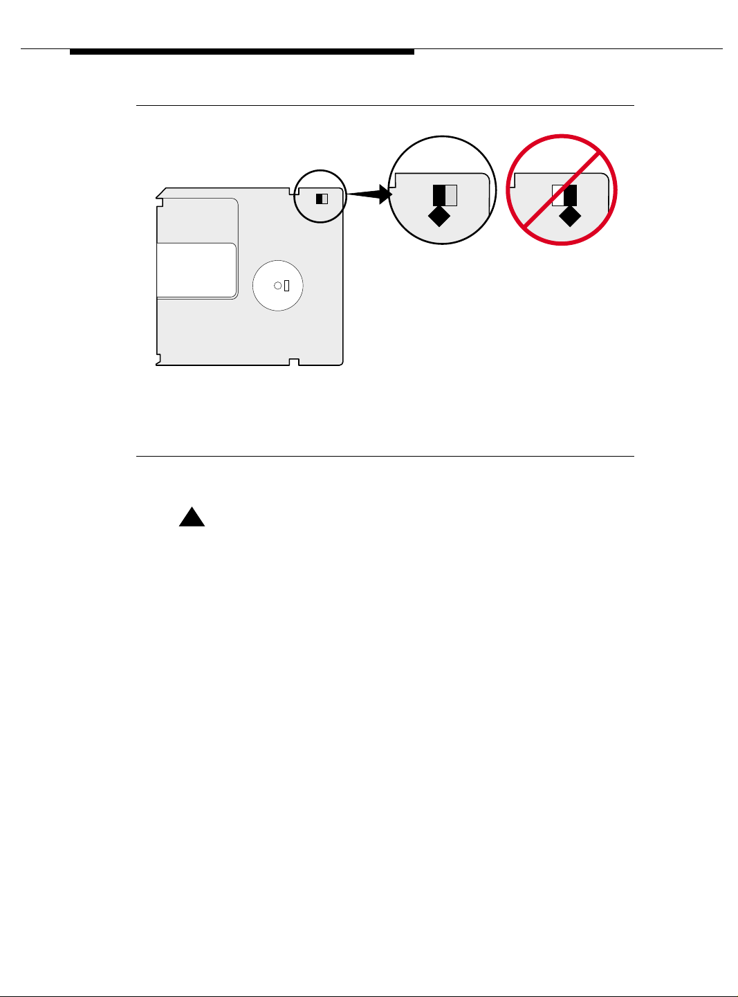
Installing a DEFINITY Server ATM-PNC
Figure Notes
1. Not Write-protected 2. Write-protected
1 2
h1dfdsk KLC 112499
Figure 3-12. Make sure the disk is not write-protected.
!
CAUTION:
The removable media has a sliding, metal cover to protect the surface
of the disk. DO NOT TOUCH THE DISK (Figure 3-13).
3-56 Issue 5 October 2002
555-233-124
Page 97

Administration
640
MB
2048
BYTES/SECTO
R
h1dfdsk1 KLC 091799
Figure 3-13. Do not touch the disk inside the cartridge.
3. Type list configuration software-versions and press Enter. Check the
software version shown in the Memory Resident, Removable Media
Resident, and Disk Resident fields. Make sure the Removable
Media Resident field shows the same software load as the other two.
!
CAUTION:
If the Memory Resident and Disk Resident fields show that the
software version is different than what’s on the removable media,
then you must back up the disk to the spare removable media before
continuing. If all fields show the same software version, they you may
save translations to the removable media.
NOTE:
If you are sending translations to several sites, you may want to save
translations to several spare removable media and send out
simultaneously.
Issue 5 October 2002
3-57555-233-124
Page 98

Installing a DEFINITY Server ATM-PNC
4. Type backup disk full and press Enter to back up the software load,
announcements, and translations to the spare removable media on the
active carrier.
or
On Each WSP
!
Deliver or Install the License File
If you have a direct switch connection:
Type save translation removable-media and press
translations to the spare removable media on the active carrier, which
takes about 2 minutes.
5. Repeat steps 2 through 4 for each spare removable media you need.
6. When done, replace the spare removable media with the original one.
7. Send the spare removable media with the updated system translations to
the first WSP location using overnight mail. Or if you saved translations to
several spare removable media, send to all locations simultaneously.
Enter to save
CAUTION:
When working with any cabinet hardware, wear a grounded wrist strap to
ground yourself against electrostatic discharge (ESD).
1. Go to the RFA website, and, following the instructions in the “Deliver to
G3r/G3si/G3csi” chapter of the RFA Job Aid, deliver the License File.
NOTE:
This procedure sends the License File to the switch and installs it.
If you do not have a direct connection:
1. Go to the RFA website, and, following the instructions in the “Deliver to
G3r/G3si/G3csi” chapter of the RFA Job Aid, deliver the License File to
your laptop/PC.
2. Open the License Installation Tool (LIT) application at your laptop/PC.
3. Use the LIT instructions to add a switch connection profile to the tool.
4. Use the LIT instructions to install the License File on the switch.
Replace Removable Media
1. Replace the existing removable media with the one with the translations
from the main PPN, label facing left, into the optical drive.
3-58 Issue 5 October 2002
555-233-124
Page 99

Administration
Verify software version
1. Log in.
2. Type list configuration software-versions and press
Enter. Check the
software version shown in the Memory Resident, Removable Media
Resident, and Disk Resident fields. If all the fields show the same
version, then copy the new translations to disk.
!
CAUTION:
If the Memory Resident and Disk Resident fields show that the WSP
software is different than what’s on the remo vable media, then you must
restore the disk.
Restore Disk
NOTE:
Until this command finishes, the system provides no user feedback on the
screen. Do not press
the screen to clear as the command finishes; erasing any success or failure
messages the system may provide.
1. Type restore disk full and press
announcements, and software load from removable media to the system
disk, which takes about 10 minutes.
2. Place a new, formatted removable media disk in the optical drive.
Enter while the command executes. Doing so causes
Enter to copy the translations,
3. Type save translations and press
Enter to copy the translations, which
takes about 2 minutes. When prompted be sure to preserve the license file
to this disk.
4. Keep this disk with the unique License File information with this WSP only.
Disconnect the Fiber
1. Physically unplug the fiber cable from the TN2305/TN2306 circuit pack
(from both the TN2305 packs if there are two) to prevent the WSP from
attempting to establish EAL connections.
Reset WSP
1. Ensure that the removable media with the unique License File information
for this WSP is in the optical drive.
2. Type reset system 3 and press Enter to reboot the system with the new
translations and License File, which takes about 2 minutes.
NOTE:
When prompted to preserve the License File or not, choose Y es. This
preserves the unique License File for this WSP only.
Issue 5 October 2002
3-59555-233-124
Page 100

Installing a DEFINITY Server ATM-PNC
Set WSP Role
1. Log in.
2. Type change system-parameters maintenance and press
3. On screen 5, type pending in the WAN Processor Role field.
4. Press
Enter to effect changes.
Remove SPE Duplication (if main PPN is high reliability)
1. Type change system-parameters duplication and press Enter.
2. Set Enable Operation of SPE Duplication field to n.
3. Press
4. Type save translations spe-a and press
5. Type reset system 3 and press
Enter to effect changes.
Enter to save translations.
Enter to reboot the system with the new
translations and License File, which takes about 2 minutes. This is
necessary to eliminate SPE duplication on the WSP.
Busyout Fiber Link
1. Log in.
2. Type list atm pnc and press
the ATM-PNC line(s) in the main PPN (either 1 or 2 lines).
3. Type busyout atm pnc number and press Enter
4. Repeat for the other ATM-PNC line, if 2.
Enter. Look for the number that corresponds to
Enter.
Remove the Fiber Link
1. Type remove atm pnc number and press Enter.
2. Repeat for the other ATM-PNC line, if 2.
3. Press
Enter to effect changes.
Remove Translated Packs
1. Type change circuit 1 and press Enter to verify that the TN2305/TN2306
boards match your configurati on .
3-60 Issue 5 October 2002
555-233-124
 Loading...