

Avaya MultiVantage Installation Manual

,QVWDOODWLRQIRU$GMXQFWVDQG3HULSKHUDOV
IRU$YD\D0XOWL9DQWDJH6RIWZDUH
Release 1.2
555-233-116
Issue 4
October 2002

Copyright 2002, Avaya Inc.
All Rights Reserved
Notice
Every effort was made to ensur e that th e informa ti on in this docume nt
was complete and accurate at the time of printing. However, information is subject to change.
Preventing Toll Fraud
“Toll fraud” is the unauthorized use of your telecommunications system by an unauthorized party (for example, a person who is not a corporate employee, agent, subcontractor, or is not working on your
company's behalf). Be aware that there may be a risk of tol l fra ud
associated with your system and that, if toll fraud occurs, it can result
in substantial additional charges for your telecommunications services.
Avaya Fraud Intervention
If you suspect that you are being victimized by toll fraud and you need
technical assistance or support, in the United States and Ca na da, call
the Technical Service Center's Toll Fraud Intervention Hotline at
1-800-643-2353.
How to Get Help
For additional support teleph one numbers, go to the Avaya Web site:
http://www.avaya.com/support/
If you are:
• Within the United States, click Escalation Lists, which includes
escalation phone numbers withi n the U SA .
• Outside the United States, click Escalation Lists then click Glo-
bal Escalation List, which includes ph one numbers for the
regional Centers of Excellence.
Providing Telecommunications Security
Telecommunications security (of voice, data, and/or video communications) is the prevention of any type of intrusion to (that is, either
unauthorized or malicious access to or use of) your company's telecommunications equi pment by some party.
Your company's “telecommunic at ions equipment ” includes both th is
Avaya product and any other voice/data/video equipment that could be
accessed via this Avaya product (that is, “networked equipment”).
An “outside party” is anyone who is not a cor pora te employee, age nt,
subcontractor, or is not working on your company's behalf. Whereas, a
“malicious party” is any one (in cl udi ng someone who may be otherwise authorized) who accesses your telecommunications equipment
with either malici ous or mischievous intent.
Such intrusions may be either to/throu gh sync hronous (time-multiplexed and/or circuit-based) or asynchronous (character-, message-, or
packet-based) equipment or interfaces for reasons of:
• Utilization (of capabilities special to the accessed equipment)
• Theft (such as, of intellectu al property, financial assets, or toll
facility access)
• Eavesdropping (privacy invasions to humans)
• Mischief (troubling, but appa re ntl y in noc uous, tampering)
• Harm (such as harmful tampering, data loss or alteration,
regardless of motive or intent)
Be aware that there may be a ri sk of unauthorized intrusions associated with your system and/or i ts networked equipment. Also realize
that, if such an intrusion shoul d oc cur, it could result in a variety of
losses to your company (includin g but not limi te d to, hum a n/ data privacy, intellectual property, material assets, financial reso urces, labor
costs, and/or legal costs).
Responsibility for Your Company’s Telecommunications Security
The final responsibility for sec uri ng both this system and its net-
worked equip m en t rests with you - Avaya’s customer system administrator, your telecommunications peers, a nd your managers. Base the
fulfillment of your responsi bility on acquired knowledge and
resources from a variety of sources in cl udi ng but not limited to:
• Installation docu ments
• System administration documents
• Security documents
• Hardware-/software-based security tools
• Shared information betwee n you and your peers
• Telecommunications security experts
To prevent intrusions to your telecommunications equipment, you and
your peers should carefully program and configure:
• Your Avaya-provided telecommunications systems and their
• interfaces
• Your Avaya-provided software applications, as well as their
• underlying hardw are/software plat form s and interfaces
• Any other equipmen t ne tworked to your Avaya products.
Voice Over In ternet Prot ocol (VoIP )
If the equipment supports Voice over Internet Protocol (VoIP) facilities, you may experienc e c ert ai n c o m promises in performance, rel iability and security, even when the equi pm e nt performs as warranted.
These compromises may become more acute if you fail to follow
Avaya's recommendations for configuration, operation and use of the
equipment. YOU ACKNOWLEDGE THAT YOU ARE AWARE OF
THESE RISKS AND THAT YOU HAVE DETERMINED THEY
ARE ACCEPTABLE FOR YOUR APPLICATION OF THE EQUIPMENT. YOU ALSO ACKNOWLEDGE THAT, UNLESS
EXPRESSLY PROVIDED IN ANOTHER AGREEMENT, YOU
ARE SOLELY RESPONSIBLE FOR (1) ENSURING THAT YOUR
NETWORKS AND SYSTEMS ARE ADEQUATELY SECURED
AGAINST UNAUTHORIZED INTRUSION AND (2) BACKING
UP YOUR DATA AND FILES.
Standards Compliance
Avaya Inc. is not responsible for any radio or television interference
caused by unauthori ze d m odifications of this equipm ent or the substitution or atta chment of connecting cables and eq uipment othe r than
those speci fie d by Avaya Inc. The correc ti on o f i nter fer enc e c aus ed b y
such unauthorized mod ifications, substitution or atta c hm ent will be
the responsibility of the user. Pursuant to Part 15 of the Federal Communications Commission (FC C) Rules, the user is cautioned that
changes or modifications not expressly approved by Avaya Inc. could
void the user ’s authority to operate this equi p ment.
Product Safety Standards
This product compli es with and co nforms to the following inte r na tional Product Safety standards as applicable:
Safety of Information Technology Equipment, IEC 60950, 3rd Edition
including all relevant national deviations as listed in Compliance with
IEC for Electrical Equipment (IECEE) CB-96A.
Safety of Information Technology Equipment, CAN/CSA-C22.2
No. 60950-00 / UL 60950, 3r d Edition

Safety Requirements for Cu stome r Equipment, ACA Technical Standard (TS) 001 - 1997
One or more of the following Mexican national standards, as applicable: NOM 001 SCFI 1993, NOM SCFI 016 1993, NOM 019 SCFI
1998
The equipment descr ibed in this document may con tain Class 1
LASER Device(s). These devices comply with the following standards:
EN 60825-1, Editio n 1. 1, 19 98-01
21 CFR 1040.10 and CFR 1040.11.
The LASER devices op erate within the foll ow i ng parameters:
• Maximum power output: -5 dBm to -8 dB m
• Center Wavelength: 1310 nm to 1360 nm
Luokan 1 Laserlaite
Klass 1 Laser Apparat
Use of controls or adjustm en ts or pe rformance of procedure s other
than those specified herein may result in hazardous radiation exposures. Contact your Avaya representative for more laser product information.
Electromagnetic Compatibility (EM C) Standards
This product complies with and conforms to the following international EMC standards and all relevant national deviations:
Limits and Methods of Measurement of Radio Interference of Information Technology Equipment, CISPR 22:199 7 and EN55022:1998.
Information Technology Equipment – Immunity Characteristics –
Limits and Methods of Measurement, CISPR 24:1997 and
EN55024:1998, including:
• Electrostatic Discharge (ESD) IEC 61000-4-2
• Radiated Immunity IEC 61000-4-3
• Electrical Fast Transient IEC 61000-4-4
• Lightning Effects IEC 61000-4-5
• Conducted Immunity IE C 61000-4-6
• Mains Frequency Magnetic Field IEC 61000-4-8
• Volt age Dips and Variations IEC 61000-4-11
• Powerline Harmonics IEC 61000-3 -2
• Voltage Fluctuations and Flicker IEC 61000-3-3
Federal Communications Commission Statement
Part 15:
For MCC1, SCC1, G600, and C M C 1 M edia Gateways:
Note: This equipment has been tested and found to comply with
the limits for a Class A digital device, pursuan t to Pa rt 15 of the
FCC Rules. These limits are designed to provide reasonable protection against h armful interferenc e when the equipmen t is op erated in a commer cial environ ment. This equipmen t generates,
uses, and can radiate radio frequency energy and, if not installed
and used in accordance with the instruction manual, may cause
harmful interf erence to radio co mmunications. Op eration of this
equipment in a residential a rea is likely to cause harmfu l interference in which case the user will be required to correct the interference at his own expense.
For the G700 Media Gateway:
Note: This equipment has been tested and found to comply with
the limits for a Class B digital device, pursuant to Part 15 of the
FCC Rules. These limits are designed to provide reasonable protection agains t h a r m ful interference in a residential installation .
This equipment generates, uses, and can radiate radio frequency
energy and, if not installed and used in accordance with the
instruction manual, may cause harmful interference to radio
communications. However, there is no guarantee that radio interference will not occu r in a particular installation. I f th is equipment does cause h armful interfe ren ce to radio or televisi on
reception, which can be determined by turning the equipment off
and on, the user is encouraged to try to co rrec t th e interference
by one or more of the following measures:
• Reorient or relocate th e receiving antenna.
• Increase the separation between the equipment and
receiver.
• Connect the equipment into an outlet on a circuit different
from that to which the receiver is connected.
• Consult the dealer or an experienced radio/TV technician
for help.
Part 68: Answer-Supervision Signaling. Allowing this equipmen t to
be operated in a manner that does not provide proper answer-supervision signaling is in violation of Part 68 rules. This equipment returns
answer-supervision signals to the public switched network w hen:
• answered by the called stat ion,
• answered by the atte nda nt, or
• routed to a recorded a nn o un cement that can be administered by
the customer premises equipment (CPE) user.
This equipment returns answer-supervision signals on all dir ec t
inward dia led (DID) ca lls forwarded back to th e pu blic switc h ed telephone network. Permissible exceptions are:
• A call is unanswered.
• A busy tone is received.
• A reorder tone is received.
Avaya attests that this registered equipment is capa ble of providing
users access to int erstate provide rs of operato r services through th e use
of access codes. Modification of this equipment by call aggregators to
block access dialing code s is a violation of the Telephone Operator
Consumers Act of 1990.
For MCC1, SCC1, G600, and CMC1 Media Gateways:
This equipm ent c ompl ies with Par t 68 of t he FCC ru l es. On the r e ar of
this equipment is a l abel that contains, among other information , th e
FCC registration number and ringer equivalence number (REN) for
this equipment. If requested, this informat ion must be provided to the
telephone company.
For the G700 Media Gateway:
This equipment compl ie s with Part 68 of th e FCC rules and the
requirements adopted by the ACTA. Located prominently on this
equipment is a label that contains, among other information, a product
identifier in the format US:AAAEQ##TXXXX. The digi ts represente d
by ## are the ringe r eq uivalence numb er (REN) without a decimal
point (for example, 03 is a REN of 0.3). If requested, this number must
be provided to the telephone company.
The REN is used to determine the qua nt it y of de vices which may be
connected to the telephone line. Excessive RENs on the telephone line
may result in devices not ringing in response to an incoming call. In
most, but not all areas, the sum of RE N s should not exceed 5.0. To be
certain of the number of devices that may be conne cted to a line, as
determined by the total RENs, contact the local telephone company.
REN is not required for som e t ype s of analog or digital facilitie s.

Means of Connection
Connection of this equipment to the telephone network is shown in the
following tables.
For MCC1, SCC1, G600, and C M C 1 M edia Gateways:
Manufacturer’s Port
Identifier
FIC Code SOC/REN/
A.S. Code
Network
Jacks
Off/On premises station OL13C 9.0F RJ2GX,
RJ21X,
RJ11C
DID trunk 02RV2-T 0.0B RJ2GX,
RJ21X
CO trunk 02GS2 0.3A RJ21X
02LS2 0.3A RJ21X
Tie trunk T L31M 9.0F RJ2GX
Basic Rate Interface 02IS5 6.0F, 6.0Y RJ49C
1.544 digital interface 04DU9-BN 6.0F RJ48C,
RJ48M
04DU9-IKN 6.0F RJ48C,
RJ48M
04DU9-ISN 6.0F RJ48C,
RJ48M
120A3 channel serv ic e unit 04DU9-DN 6.0Y RJ4 8C
A plug and jack used to connect this equipment to the premises wiring
and telephone network mu st co mply with the applicable FC C Part 68
rules and requirements adopt ed by the ACTA. A compliant telephone
cord and modular plug is provided with this prod uct . It is de signed to
be connected to a compatible modular jack that is also compliant. It is
recommended that repairs be performed by Avaya certified techni cians.
The equipment cannot be use d on public coin phone service prov id ed
by the telephone compa ny. Connection to party line service is subject
to state tariffs. Co ntact the state public utility commission, publ ic service commission or corporation commission for inf or ma tion.
This equipment, if i t use s a tel e phone receiver, is hearing aid c om patible.
Canadian Department of Communications (DOC) Interference
Information
For MCC1, SCC1, G600, and CMC1 Media Gateways:
This Class A digital apparat us complies with Canadia n ICE S -003.
Cet appareil numérique de la classe A est conforme à la norme
NMB-003 du Canada.
For the G700 Media Gateway:
This Class B digital apparatu s com pl ie s with Canadian ICES-003.
For the G700 Media Gateway:
Manufacturer’s Port
Identifier
FIC Code SOC/REN/
A.S. Code
Network
Jacks
Ground Start CO trunk 02GS2 0.5A R J11C
DID trunk 02RV2-T AS.0 RJ11C
Loop Start CO trunk 02LS2 0.5A R J11C
1.544 digital interface 04DU9-BN 6.0Y RJ48C
04DU9-DN 6.0Y RJ48C
04DU9-IKN 6.0Y RJ48C
04DU9-ISN 6.0Y RJ48C
Basic Rate Interface 02IS5 6.0F RJ49C
If the terminal equipment (for example, the MultiVantage
™ Solution
equipment) causes harm to the telephone net w ork, the telephone co mpany will notify you in advance that temporary discontinuance of service may be required. But if a dvance notice is not pra ct ic al , t he
telephone company will notify the customer as soon as possible. Also,
you will be advised of your right to file a complaint with the FCC if
you believe it is necessary.
The telephone company may make changes in its facilities, equipment,
operations or procedure s tha t co uld affect the operation of the equipment. If this happens, the telephone company will provide advance
notice in order for you to make ne cessary modificatio ns to main tain
uninterrupted service.
If trouble is experience d w i th t his equipment, for repair or warranty
information, pl ea s e contact the Technical Service Center at
1-800-242- 2121 or contact your local Avaya representative. If the
equipment is causing ha rm to the telephone network, the telephone
company may requ est tha t you disconnect the equipment until the
problem is resolved.
Cet appareil numérique de la cla sse B est conforme à la norm e
NMB-003 du Canada.
This equipment me ets the appl icab le In dus try Can ada Terminal Equipment Technical Specifications. This is confirmed by the registration
number. The abbreviation, IC, before the registration number signifies
that registration was performed based on a Declaration of Conformity
indicating that Industry Canada technical specifi ca tions were met. It
does not imply that Industry Canada approved the equipment.
DECLARA TIONS OF CONFORMITY
United States FCC Part 68 Supplier’s Declaration of Conformity
(SDoC)
Avaya Inc. in the United States of America hereby certifies that the
equipment describe d in this document an d be aring a TIA TSB-168
label identification number complies with the FCC’s Rules and Regulations 47 CFR Part 68, and the Administrative Council on Terminal
Attachments (ACTA) adopted technical criteria.
Avaya further asserts that Avaya handset-equipped terminal equipment described in this document complies with Paragraph 68.316 of
the FCC Rules and Regulations de fining Hearing Aid Compat ibili ty
and is deemed compatible w ith hearing aids.
Copies of SDoCs signed by the Responsible Par ty i n the U. S. can be
obtained by contactin g your local sales representa ti ve and are available on the following Web site:
http://www.avaya.com/support/
All MultiVantage
™ system products are com pli a n t wi th FCC Part 68,
but many have been registered with the FCC before the SDoC process
was available. A list of all Avaya registered prod ucts may be found at:
http://www.part68.org/
by conducting a search using “Avaya” as manufacturer.
European Union Declarations of Conformity
Avaya Inc. declares that the equipment specified in this document
bearing the “CE” (Conformité Europeénne) m a rk conforms to the
European U nion Radi o and Teleco m munication s Terminal Equipment
Directive (1999/5/EC), including the Electromagnetic Compatibility
Directive (89/336/EEC) and Low Voltage Directive (73/23/EEC). This
equipment has been certified to meet CTR3 Basic Rate Interface (BRI)
and CTR4 Primary Rate Interface (PRI) and subsets thereof in CTR12
and CTR13, as applicable.
Copies of these Declarat io ns of Conformity (DoCs) can b e ob ta in ed
by contacting your loc al sale s representative and ar e available on the
following Web site:
http://www.avaya.com/support/
Japan
For MCC1, SCC1, G600, and C M C 1 M edia Gateways:
This is a Class A product based on the sta ndard of the Voluntary Control Council for Interference by Information Technology Equipment
(VCCI). If this equipment is used in a domestic en vironmen t, radio
disturbance may occur, in which case, the user may be required to take
corrective actions.
For the G700 Media Gateway:
This is a Class B product based on the standard of the Voluntary Control Council for Interference by Information Technology Equipment
(VCCI). If this equipment is used in a domestic en vironmen t, radio
disturbance may occur, in which case, the user may be required to take
corrective actions.
To order copies of this and other documents:
Call: Avaya Publications Center
Voic e 1. 800.457.1235 or 1.207.866.6701
FAX 1.800.457.1764 or 1.207.626.7269
Write: Globalware Sol u tions
200 Ward Hill Avenue
Haverhill, MA 01835 USA
Attention: Avaya Account Management
E-mail: totalware@gwsmail.com


Contents
Issue 4 October 2002 7555-233-116
About this book 15
■ Overview 15
■ Conventions used in this book 18
Systems and circuit packs 19
Admonishments 19
Physical dimensions 20
■ Antistatic protection 20
■ Remove/install circuit packs 20
■ Security 21
■ Standards compliance 21
■ LASER product 22
■ Trademarks 22
■ How to get this book on the Web 22
■ How to get help 23
■ Tell us what you think 23
1 909A/B universal coupler 25
2 Auxiliary power supplies 29
■ Local auxiliary power supply 30
■ Applications that require auxiliary power 30
■ Sources of auxiliary local power 31
■ Required safety precautions 31
■ 1145B power supply 32
Circuit protection 32
Mountings 33
Installing the wall mounting 33
Installing the 1146 power distribution unit 35
Installing the expanded power distribution unit 36
Powering up and testing AC and DC power 38

Contents
Wire the 1146 power distribution unit 39
Replacing the batteries 40
Storing the batteries in inactive units 40
Repairing short circuits and resetting red LEDs 40
■ 1151A and 1151A2 power supplies 40
Desk mounting 42
Wall mounting 42
Standards compliance 42
3 Extenders for 2-wire DCP endpoints 43
■ 2-wire DCP endpoints 43
■ DCP extender, stand alone 45
■ DCP extender, rack mount 46
4 Data modules and asynchronous data units 47
■ Understanding RS-232 communications 48
■ Installation procedure 49
■ Obtain required equipment 50
■ Set hardware options 50
Setting 7400A data module hardware options 50
Setting 7400B data module hardware options 52
■ Connect data modules 54
Connecting a single data module 55
Connecting multiple data modules to the system 56
■ Administer the data modules 95
■ Asynchronous data units (ADU) 98
555-233-1168 Issue 4 October 2002

Contents
Issue 4 October 2002 9555-233-116
5 External modems 99
■ Hardware required when configuring modem s 99
■ Paradyne COMSPHERE 3715 100
Configuring the 3715 for CMS 100
Configuring the 3715 for modem pooling 100
■ Paradyne COMSPHERE 3810 Plus and 3811 Plus 101
Configuring the 3810 Plus and 3811 Plus modems 101
■ Paradyne COMSPHERE 3910 101
Configuring the 3910 for CMS 102
■ U.S. Robotics modems 109
Configuring U.S. Robotics modems 109
■ Multi-Tech MT5634ZBA-USB 110
Configuring the MT5634ZBA-USB modem 110
■ Administration 110
6 Printers 113
■ Connecting printers using TCP/IP 113
Task list 113
Administering adjunct parameters 114
Using the downloadable reliable session-layer
protocol (RSP) tool 115
7 DEFINITY LAN gateway system 117
■ What is the DEFINITY LAN gateway? 117
How the DLG application works 117
How is the DLG application is packaged 118
The MAPD DLG 118
The co-resident DLG 119
Switch-based connectivity — co-resident DLG 119

Contents
8 Terminal server installation 121
■ Overview 121
■ Installing and administering the terminal server 122
Administering the IOLAN+ 124
Potential failure scenarios and repair actions 131
■ Administering IP node names 131
■ Administering IP services 132
9 DS1/T1 CPE loopback jack 135
■ Installing a loopback jack 135
With a smart jack 135
Without a smart jack 136
■ Administering the loopback jack 137
■ Loopback testing with a smart jack 137
Testing the DS1 span from the ICSU to the loopback jack 137
Testing the DS1 span from the smart jack to the
network interface termination or fiber multiplexer (MUX) 143
Testing the DS1 span from the loopback jack to
the smart jack 143
■ Testing a loopback jack without a smart jack 151
Configurations using fiber multiplexers 156
10 ISDN converters and adapters 157
■ Converters for single-carrier cabinets 158
PRI-to-DASS and PRI-to-DPNSS converters 158
PRI-to-BRI converter 159
■ Converters for multi-carrier cabinets 160
PRI-to-DASS and PRI-to-DPNSS converters 160
PRI-to-BRI converter 161
555-233-11610 Issue 4 October 2002

Contents
Issue 4 October 2002 11555-233-116
11 Stratum 3 clock 163
■ Set clock options 163
Cabling the Stratum 3 clock 165
Stratum 3 clock wiring installation procedure 167
12 Busy tone disconnect equipment for
non-U.S. installations 171
13 Call detail recording (CDR) option settings 173
■ Connecting CDR equipment 173
■ Using other equipment as the CDR output devices 174
■ Sources of administration information 174
■ Connecting a CDR device 174
Task list 174
Administering CDR parameters 174
■ Using the downloadable reliable
session-layer protoc ol (R SP ) tool 176
14 DEFINITY INADS 179
Analog loopback 179
Administration 181
Partner installation 181
INADS connection with power fail transfer 182
INADS connection without power fail transfer 184
PARTNER administration 185
DEFINITY ECS administration 186
Installation test (all installations) 187
■ Connectivity for INADS on S8700 and S8300 media servers 187
Example of an ART script file 187

Contents
15 Malicious call trace 189
16 Music-on-hold 191
■ For MCC1, SCC1, CMC1, and G600 Media Gateways 191
Registered music source 192
Nonregistered music source 192
■ For G700 Media Gateways 194
17 Paging and announcement equipment 197
■ Background information 197
IP configurations 198
Configuration using the S8700 Media Server in a
multi-connect configuration controlling a G700
Media Gateway 198
S8700 Media Server in a multi-connect configuration networked
with a S8300 Media Server in a G700 Media Gateway and a
DEFINITY CSI 199
Configuration using the S8700 Media Server with IP connect 200
■ Loudspeaker paging for MCC1, SCC1,
CMC1, or G600 Media Gateways 201
Loudspeaker paging without paging adapter 202
Loudspeaker paging access without universal coupler 203
Loudspeaker paging with universal coupler 203
■ ESPA radio paging 204
■ External ringing 205
■ Queue warning indicator 205
■ Loudspeaker paging for G700 Media Gateways 206
555-233-11612 Issue 4 October 2002

Contents
Issue 4 October 2002 13555-233-116
18 Multimedia communications
products: MMCX, MMCH, ESM 207
■ MASI for MMCX 207
Direction connection 208
Main distribution frame connection 209
■ Wideband endpoints 209
Nonsignaling configuration 209
Signaling configuration 210
■ Multimedia call handling (MMCH) 212
Connect the endpoints 212
Setup and test the MMCH installation 214
Place conversion test call 221
Expansion services module 221
Administration 222
Place test call 223
Troubleshooting 223
19 Property management system (PMS) 225
■ Connecting the property management system (PMS) 225
■ Connecting a terminal and/or journal printer 226
Using data modules 226
Using an asynchronous data unit (ADU)
and a data line circuit pack 227
■ Connecting PMS and printers using TCP/IP 227
Task list 227
Administering adjunct parameters 228
Using the downloadable reliable session-layer protocol tool 229

Contents
A Connector and cable pinout charts 231
IN Index 243
555-233-11614 Issue 4 October 2002

Issue 4 October 2002 15555-233-116
About this book
This book provides procedures for installing software (adjuncts) and equipment
(peripherals) to Avaya media servers and gateways. Not all adjuncts and
peripherals are addressed in this book. For those adjuncts and peripherals not
addressed, we are supplying other resources for the information.
The information in this book is intended for use by:
■ Trained field installation and maintenance personnel
■ Technical support personnel
■ Network engineers and technicians
■ Design center personnel
■ Sales associates
■ Business partners
Overview
Avaya media servers and gateways can work with a wide range of external
equipment, applications, and peripherals. For the purposes of this book, we define
the terms as follows:
■ Adjuncts are software products that work with the various Avaya servers or
gateways.
■ Peripherals are hardware products that connect directly or remotely to
Avaya media servers or gateways.
Be aware that some equipment and software work only with certain releases. See
your Avaya representative for the most current compatibility information.

About this book
Table 1 provides a list of current adjuncts and peripherals, and where installation
information exists.
Table 1. Adjuncts and peripherals resource list
Adjunct/Peripheral Resource
909A/B Universal Coupler Chapter 1
AUDIX AUDIX Installation
AUDIX Voice Power Installation and Maintenance Guide
Auxiliary Pow er Su ppl ie s Chapter 2
Basic Call Management
Basic Call Management System (BCMS) Operations
System (BCMS) View
Busy Tone Disconnect
Chapter 12
Equipment for Non-U.S.
Installations
Call Detail Recording
Chapter 13
(CDR) Option Settings
CallVisor ASAI LAN
Gateway
CallVisor ASAI DEFINITY LAN Gateway over MAPD
Installation, Administration, and Maintenance
CentreVu Agent CentreVu Agent Installation and Administration
CentreVu Call Management
System (CMS)
CentreVu Call Management System Software Installation
and Setup
CentreVu Explorer CentreVu Explorer User Guide
CentreVu Supervisor CentreVu Supervisor —Installation and Getting Started
Conversant INTUITY CONVERSANT System Customer Assist
Technical Operations
Data Modules and ADUs Chapter 4
DCS Connections Chapter 9
DEFINITY INADS Chapter 14
DEFINITY LAN Gateway
System
DEFINITY Wireless
Personal Comm Mgr.
DS1/T1 CPE Loopback
Jack
Expansion Services Module
(ESM)
16 Issue 4 October 2002
Chapter 7
Interface for the DEFINITY Wireless Business System
Guide
Chapter 9
Chapter 18
Continued on next page
555-233-116

Overview
Issue 4 October 2002
17555-233-116
External Alerting
Equipment
Chapter 16
Internet Call Center CentreVu Internet Solutions Documentation CD-ROM
Internet Call Center Solution Guide
Internet Telephony
Gateway
Internet Telephony Server-Enterprise Hardware Installation
Quick Reference
Intuity AUDIX
Internet Messaging for the Intuity AUDIX Multimedia
Messaging System, Installation
Intuity Interchange INTUITY Interchange System Supporting Documentation
ISDN Converters and
Adapters
Chapter 10
Loudspeaker Paging Chapter 17
Malicious Call Trace Chapter 15
Modems, external Chapter 5
Multimedia Call Exchange
MMCX
Chapter 18
Multimedia Call Handling
(MMCH)
Chapter 18
Multipoint Control Unit
(MCU)/CRS
MultiPoint Conferencing Unit Installation and Test
Music-on-hold Chapter 16
Paging and Announcement
Equipment
Chapter 17
Pollable Storage Unit
(PSU)
Pollable Storage Unit Installation
Printers Chapter 6
Property Management
System
Chapter 19
Stratum 3 Clock Chapter 11
Voice and Data Terminals Chapter 3
Table 1. Adjuncts and peripherals resource list
Adjunct/Peripheral Resource
Continued on next page

About this book
Conventions used in this book
Become familiar with the following terms and conventions. They help you use this
book with your Avaya MultiVantage™ Software.
■ Commands are printed in bold face as follows: command.
We show complete commands in this book, but you can usually type an
abbreviated version of the command. For example, list configuration
station can be typed as list config sta.
■ Screen displays and names of fields are printed in constant width as
follows: screen display.
A screen is any form displayed on your computer or terminal monitor.
■ Variables are printed in italics as follows: variable.
■ Keys and buttons are printed as follows: KEY.
■ To move to a certain field, you can use the TAB key, arrows, or the ENTER
key (the
ENTER key may appear as the RETURN key on your keyboard).
■ If you use terminal emulation software, you need to determine what keys
correspond to
■ In this book we use the terms “telephone” and “voice terminal” to refer to
ENTER, RETURN, CANCEL, HELP, NEXT PAGE, etc.
phones.
■ We show commands and screens from the newest release of MultiVantage
Software and refer to the most current books. Please substitute the
appropriate commands for your system and refer to the manuals you have
available.
■ If you need help constructing a command or completing a field entry,
remember to use
— When you press
HELP.
HELP at any point on the command line, a list of
available commands appears.
— When you press HELP with your cursor in a field on a screen, a list of
valid entries for that field appears.
■ The status line or message line can be found near the bottom of your
monitor display. This is where the system displays messages for you.
Check the message line to see how the system responds to your input.
Write down the message if you need to call our helpline.
■ When a procedure requires you to press ENTER to save your changes, the
screen you were working on clears and the cursor returns to the command
prompt.
The message line shows “command successfully completed” to
indicate that the system accepted your changes.
18 Issue 4 October 2002
555-233-116

Conventions used in this book
Issue 4 October 2002
19555-233-116
Systems and circuit packs
■ The word “system” is a general term encompassing all references to an
Avaya media server or gateway running MultiVantage Software.
■ The term “ASAI” is synonymous with the newer CallVisor ASAI.
■ Circuit pack codes (for example, TN780 or TN2182B) are shown with the
minimum acceptable alphabetic suffix (like the “B” in the code TN2182B).
Generally, an alphabetic suffix higher than that shown is also acceptable.
However, not every vintage of either the minimum suffix or a higher suffix
code is necessarily accep t ab le. A suffix of “P” means that firmware can be
downloaded to that circuit pack.
■ The term “cabinet” refers to the external casing (shell) of an MCC1, SCC1,
CMC1, or G600 Media Gateway. Circuit packs are installed in the cabinet
in a specific carrier (row) and in a specific slot within that carrier.
■ The designation “UUCSSpp” refers to the location (address) of a circuit
pack in cabinet-carrier-slot order. In this address designation, UU is the
cabinet number, C is the carrier letter, SS is the slot number of a specific
circuit pack, and pp (if applicable) is a specific port on the circuit pack. A
sample address for port 4 on a circuit pack on an MCC1 Media Gateway
might look like this: 02A0704.
■ A G700 Media Gateway uses media modules instead of circuit packs. The
media module address is designated as XXXVSpp, where XXX is the
administered number of the G700 Media Gateway, VS is th e slot n umber of
a specific media module location on the G700 Media Gateway, and pp (if
applicable) is a sp ecific port on the me dia module. The V is not a variable
and needs to be included in the command exactly where shown. A sample
address for port 4 on an MM711 Media Module on a G700 Media Gateway
might look like this: 002V304. An S8300 Media Server, if installed in a
G700 Media Gateway, must be in location V1.
Admonishments
Admonishments in this book have the following meanings:
Tip:
Draws attention to information that you may find helpful.
NOTE:
Draws attention to information that you must heed.
!
CAUTION:
Denotes possible harm to software, possible l oss of data, or pos si ble service
interruptions.

About this book
!
WARNING:
Denotes possible harm to hardware or equipment.
!
DANGER:
Denotes possible harm or injury to your body.
!
SECURITY ALERT:
Indicates when system administration may leave your system open to toll
fraud.
Physical dimensions
■ All physical dimensions in this book are in English units (feet [ft]) followed
by metric (centimeter [cm]) in parenthesis.
■ Wire gauge measurements are in AWG followed by the diameter in
millimeters in parenthesis
Antistatic protection
!
WARNING:
To minimize electrostatic discharge (ESD), always wear an authorized wrist
ground strap. Connect the strap to an approved ground, such as an
unpainted metal surface, before handling circuit packs, media modules, or
any components.
Remove/install circuit packs
!
CAUTION:
Do not remove or install control circuit packs (circuit packs with white labels)
when the power is on in an MCC1 Media Gateway. Damage may occur.
Make sure the power is off before removing or installing control circuit packs.
Port circuit packs (circuit packs with gray labels—older version circuit packs
had purple labels) can be safely removed or installed when the power is on.
Do not remove or install media modules when the power is on in a
G700 Media Gateway. Damage may occur. Make sure the power is off
before removing or installing a media module.
20 Issue 4 October 2002
555-233-116

Security
Issue 4 October 2002
21555-233-116
Security
To ensure the greatest security possible, Avaya offers services that can reduce
toll fraud liabilities. Contact your Avaya representative for more security
information.
Login security is an attribute of the MultiVantage Software. Advise customers that
their existing passwords expire 24 hours after the upgrade. Also explain that the
new passwords must conform to strict requirements.
System administrators must keep network addresses confidential. A PPN or any
endpoint masquerading as a PPN on the ATM network can seize that EPN and
control it if that EPN is not already connected to its proper PPN.
Standards compliance
The equipment in this document complies with the following standards (as
applicable):
■ ITU-T (Formerly CCITT)
■ ECMA
■ ETSI
■ IPNS
■ DPNSS
■ National ISDN-1
■ National ISDN-2
■ ISO-9000
■ ANSI
■ FCC Part 15 and Part 68
■ EN55022
■ EN50081
■ EN50082
■ UNI 3.1
■ CISPR22
■ Australia AS3548 (AS/NZ3548)
■ Australia AS3260
■ IEC 825
■ IEC 950
■ UL1459

About this book
■ UL 1950
■ CSA C222 Number 225
■ TS001
■ ILMI 3.1
LASER product
The Avaya Media Gateway may contain a Class 1 LASER device (IEC 825 1993)
if single-mode fiber optic cable is connected to a remote expansion port network
(EPN). The LASER device operates within the following parameters:
Power output Wavelength Mode field diameter
-5 dBm 1310 nm 8.8 mm
!
DANGER:
Use of controls or adjustments or performance of procedures other than
those specified herein may result in hazardous radiation exposure.
Contact your Avaya representative for more information.
Trademarks
All trademarks identified by ® or ™ are registered trademarks or trademarks,
respectively, of Avaya, Inc. All other trademarks are the property of their
respective owners.
How to get this book on the Web
If you have internet access, you can view and download the latest version of this
book. To view the book, you must have a copy of Acrobat Reader.
To access the latest version:
1. Access the Avaya Web site at http://www.avaya.com/support/.
2. Click Pr oduct Docu mentatio n.
3. In the Search Product Documentation dialog box, type the ID number of
this book (555-233-116) and click Search.
4. Find the latest issue number, then click the book title.
5. Download this book.
22 Issue 4 October 2002
555-233-116

How to get help
Issue 4 October 2002
23555-233-116
How to get help
If you need additional help, the following resources are available. You may need
to purchase an extended service agreement to use some of these resources. See
your Avaya representative for more information.
■ If you are within the United States, go to the Avaya Web site at
http://www.avaya.com/support/ for support telephone numbers. Click
Escalation Lists, which includes escalation phone numbers within specific
regions of the United States.
■ For all international resources, contact your local Avaya authorized dealer
for any additional help and questions.
Tell us what you think
Let us know what you like or don’t like about this book. Although we can’t respond
personally to all your feedback, we promise we will read each response we
receive.
Write to us at: Avaya Inc.
Product Documentation Group
1300 W. 120th St.
Westminster, CO 80234 USA
Fax to: 303-538-1741
Send email to: document@avaya.com

About this book
24 Issue 4 October 2002
555-233-116

Issue 4 October 2002 25555-233-116
1
909A/B universal coupler
The 909A/B universal coupler is used with paging and music-on-hold equipment
that is not approved for use with the public network.
NOTE:
The information in this chapter does not apply to the G700 Media Gateway
configurations.
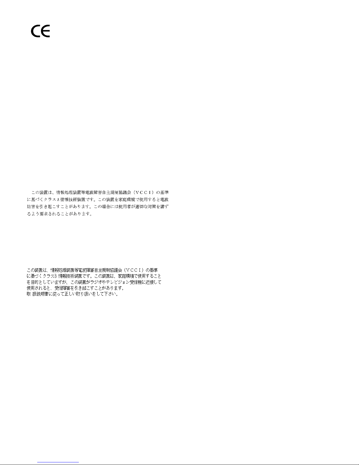
Figure 1 shows a typical 909A/B universal coupler. For additional installation and
switch setting information, refer to 909A/909B Universal Coupler Installation
Instructions.
NOTE:
If the music source is registered by the FCC (in the USA) or an equivalent
body, the 909A/B universal coupler is not required.
909A/B universal coupler
1. 909A/B universal coupler
2. J1 8-pin modular jack
3. J2 8-pin modular jack
909_brkt KLC 042296
4. J3 7-pin modular jack
5. DIP switch location
Figure 1. Typical 909A/B universal coupler
The 909A is the direct current (DC) version of the coupler, and cabinet power
supplies -48 VDC power. The 909B is the alternating current (AC) version, and
power is supplied from a separate power supply (such as the KS-22911L2).
The DIP switches on the unit set:
■ Protection/Paging selection — For AUX trunk paging and malicious call
trace, set to C2. Set the switch to C1 for all other applications.
■ Output attenuation (-9 or -15 dBm) — Setting depends on output level of
music source.
■ Output impedance (8 ohms, 1.5 kΩ, and 50 kΩ) —This switch only
requires setting if the Protection/Paging switch is set to C2 and the coupler
is supplying background music to a customer-supplied paging amplifier.
The pinouts for J1, J2, and J3 are provided in Tab le 2, Table 3, and Table 4. Refer
to these tables when connecting music or paging equipment.
26 Issue 4 October 2002
555-233-116

909A/B universal coupler
Issue 4 October 2002
27555-233-116
!
CAUTION:
Do not plug the cable into J3 before all cross-connects are completed.
Damage to the 909A/B universal coupler may occur.
Table 2. J1 Pin Assignments (System Connections)
Pin Color Designation Description
1 White-Orange — Not Used
2 Orange PG2/BZ2 Seizure control lead, connected to -48 VDC from
the system or from the 909A/B when the protection
paging switch is set to C2, or to -48 VDC on the
909A/B when protection/paging switch is set to C1
3 White-Green PG1/BZ1 Seizure control lead, connected to SZ lead from
the AUX trunk when the protection/paging switch
is set to C2, or to -48 VDC on the 909A/B when the
protection/paging switch is set to C1
4 Blue R Ring lead
5 White-Blue T Tip lead
7 Green BSY2/BY2 Busy/busy-out lead, connected to S1 lead from the
AUX trunk
7 White-Brown BSY1/BY1 Busy/busy-out lead, connected to S lead from the
AUX trunk
8Brown — Not Used
Table 3. J2 Pin Assignments (Accessory Connections)
Pin Color Designation Description
1 White-Orange CMS1/M1 Customer-supplied music source
2 Orange CMS2/M2 Customer-supplied music source
3 White-Green COS1 Remote busy-out control contact closure from
music source
4 Blue CR Customer ring lead
5 White-Blue CT Customer tip lead
7 Green COS2 Remote busy-out control contact closure from
music source
7 White-Brown CBS1/C1 Seizure indication provided to music source
8 Brown CBS2/C2 Seizure indication provided to music source
909A/B universal coupler
2
Table 4. J3 Pin Assignments (Power Connections)
Pin Color Designation Description
1, 3, 4, & 7 —— Not used
2 Black GRD -48 RET or gr oun d lead from s yste m or
5 Yellow -48 VDC -48 VDC from system or from negative
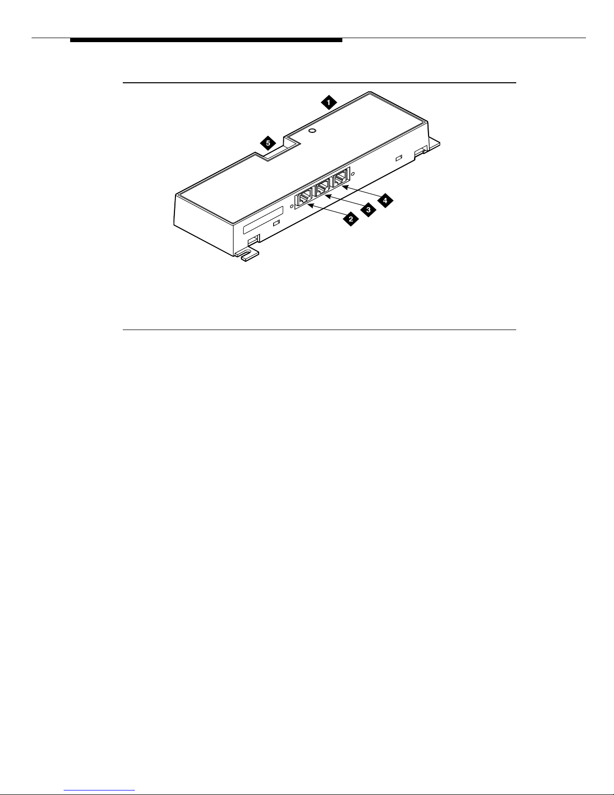
Figure 2 shows the physical locations of the pins for J1, J2, and J3.
from positive lead of power supply
lead of power supply
18
mod_jack RBP 041796
5
1. J1 and J2 8-pin modular jacks 2. J3 7-pin modular jack
Figure 2. Typical modular jack pinout
28 Issue 4 October 2002
555-233-116

Issue 4 October 2002 29555-233-116
2
Auxiliary power supplies
Nonessential features of the attendant console, such as the optional 27B1
selector console as well as DCP terminals, derive their power from an auxiliary
power source. One console can connect to an Avaya DEFINITY
®
Server CSI, and
three consoles can connect to each cabinet stack on an Avaya DEFINITY
®
Server R.
Each cabinet can derive auxiliary power from the system and through the auxiliary
cable located in the trunk/auxiliary field. Auxiliary power for a primary attendant
console should be provided through this cable so the console remains fully
operational during short power outages.
NOTE:
The information in the first part of this chapter concerning auxiliary power
supplies for the gateway itself (page 30 through page 40) does not apply to
the G700 Media Gateway.
Information beginning on page 40, ‘‘1151A and 1151A2 power supplies’’,
does apply to a G700 Media Gateway under the following conditions:
■ if a particular endpoint or adjunct uses a 1151A or 1151A2 power
supply, and
■ if that endpoint or adjunct is supported on an S8300/G700.
Please see your Avaya representative for more information.

Auxiliary power su ppl ies
Local auxiliary power supply
Consoles can use either local or phantom power, depending on the distance
between the console and the cabinet. Over short distances, phantom power is
attractive because no additional hardware is necessary—power is supplied using
the telephone circuit itself. For longer distances, you need a local power supply.
Table 5 shows cabling distances for the 302 attendant console.
Table 5. 302C1 Attendant Console Cabling Distances
24 AWG Wire
(0.27 mm
feet meters feet meters
With selector console:
Phantom-powered 800 244 500 152
Locally powered 5000 1524 3400 1037
Without selector console:
Phantom powered 1400 427 900 274
Locally powered 5000 1524 3400 1037
Applications that require auxiliary
power
Auxiliary power (local or bulk) is always re quire d for the foll owi ng:
■ Any 8520 telephone
■ 302-series attendant console
2
27 AWG Wire
)
(0.14 mm2)
■ Pa ssag eWay adapter interfa ce
■ Any 7500-series telephone whether in passive bus, or point to point (one
per BRI port)
■ Any 7500- or 8500-series telephone with an asynchronous data module
■ Any 8510 telephone in passive bus or with an asynchronous data module
(unless the 8510 will not be used to support data or video)
■ Any 7400-series telephone with XM24 expansion module
■ Any 7400-series telephone with adjuncts 7407, 7434 or 7444
■ Any 8400-series telephone with adjuncts 8411 or 8434
■ Any 4600-series IP telephone
■ IP console
The 1145B power supply is required for all installations outside the United States.
30 Issue 4 October 2002
555-233-116
 Loading...