

Page 1

Enterprise: Common
Solution Integration Guide
for Multisite Business
Communications Manager
Systems
NN49000-303
.
Page 2

Document status: Standard
Document version: 01.01
Document date: 29 June 2007
Copyright © 2007, Nortel Networks
All Rights Reserved.
The information in this document is subject to change without notice. The statements, configurations, technical
data, and recommendations in this document are believed to be accurate and reliable, but are presented without
express or implied warranty. Users must take full responsibility for their applications of any products specified in this
document. The information in this document is proprietary to Nortel Networks.
Nortel, the Nortel logo and the Globemark are trademarks of Nortel Networks.
Microsoft, MS, MS-DOS, Windows, and Windows NT are registered trademarks of Microsoft Corporation.
All other trademarks and registered trademarks are the property of their respective owners.
Sourced in Canada.
Page 3

Contents
How to get help 5
Finding the latest updates on the Nortel Web site 5
Getting help from the Nortel Web site 6
Getting help over the phone from a Nortel Solutions Center 6
Getting help from a specialist by using an Express Routing Code 6
Getting help through a Nortel distributor or reseller 6
About this document 7
Audience 7
Related information 7
Overview 9
Prerequisites 11
Knowledge requirements 11
Capturing integration parameters 11
Establishing the system baseline 12
3
Training 11
BCM 200/400 Release 4.0 configuration 17
BCM 200/400 Release 4.0 configuration procedures 17
Configuring incoming VoIP trunks 17
Verifying system license and keycodes 18
Configuring VoIP trunk media parameters 19
Configuring local Gateway parameters 23
Configuring VoIP lines 28
Configuring target lines 33
BCM 200/400 Release 3.7 configuration 37
BCM 200/400 Release 3.7 configuration procedures 37
Verifying incoming VoIP trunks provisioning 37
Adding keycodes files 38
Adding a functionality-specific keycode 38
Configuring VoIP H.323 trunk media parameters 39
Configuring VoIP SIP trunk media parameters 40
Configuring H.323 local Gateway IP parameters 41
Configuring SIP local Gateway IP parameters 42
Solution Integration Guide for Multisite Business Communications Manager Systems
Copyright © 2007, Nortel Networks
.
Enterprise: Common
NN49000-303 01.01 Standard
Release 4.0, 3.7 29 June 2007
Page 4

4 Contents
Configuring SIP subdomains 43
Configuring remote H.323 Gateways 44
Configuring remote SIP endpoints 45
Configuring VoIP lines for outgoing calls 46
Configuring target lines for incoming calls 49
Configuring telephones to access outgoing VoIP lines 50
BCM50 configuration 51
BCM50 configuration procedures 51
Configuring incoming VoIP trunks 51
Verifying system license and keycodes 52
Configuring VoIP trunk media parameters 53
Configuring local Gateway parameters 57
Configuring VoIP lines 61
Configuring target lines 65
Solution Integration Guide for Multisite Business Communications Manager Systems
Copyright © 2007, Nortel Networks
.
Enterprise: Common
NN49000-303 01.01 Standard
Release 4.0, 3.7 29 June 2007
Page 5

How to get help
This chapter explains how to get help for Nortel products and services.
Finding the latest updates on the Nortel Web site
The content of this documentation is current at the time of product release.
To check for updates to the latest documentation and software for Business
Communications Manager (BCM), click one of the following links:
5
For the...
Latest BCM 200 software Nortel page for BCM 200 software located at:
Latest BCM 400 software Nortel page for BCM 400 software located at:
Latest BCM50 software Nortel page for BCM 400 software located at:
Latest BCM 200 documentation Nortel page for BCM 200 documentation
Latest BCM 400 documentation Nortel page for BCM 200 documentation
Go to...
http://www130.nortelnetworks.com/go/main.jsp
?cscat=SOFTWARE&resetFilter=1&poid=8236
http://www130.nortelnetworks.com/go/main.jsp
?cscat=SOFTWARE&resetFilter=1&poid=171
41
http://www130.nortelnetworks.com/go/main.jsp
?cscat=SOFTWARE&resetFilter=1&poid=151
81
located at:
http://www130.nortelnetworks.com/go/main.jsp
?cscat=DOCUMENTATION&resetFilter=1&poi
d=8236
located at:
http://www130.nortelnetworks.com/go/main.js
p?cscat=DOCUMENTATION&resetFilter=1&p
oid=17141
Latest BCM50 documentation Nortel page for BCM 200 documentation
located at:
http://www130.nortelnetworks.com/go/main.js
p?cscat=DOCUMENTATION&resetFilter=1&p
oid=15181
Solution Integration Guide for Multisite Business Communications Manager Systems
Copyright © 2007, Nortel Networks
.
Enterprise: Common
NN49000-303 01.01 Standard
Release 4.0, 3.7 29 June 2007
Page 6

6 How to get help
Getting help from the Nortel Web site
The best way to get technical support for Nortel products is from the Nortel
Technical Support Web site:
w
ww.nortel.com/support
This site provides quick access to software, documentation, bulletins, and
tools to address issues with Nortel products. From this site, you can:
•
download software, documentation, and product bulletins
•
search the Technical Support Web site and the Nortel Knowledge Base
for answers to technical issues
•
sign up for automatic notification of new software and documentation
for Nortel equipment
•
open and manage technical support cases
Getting help over the phone from a Nortel Solutions Center
If you do not find the information you require on the Nortel Technical Support
Web site, and you have a Nortel support contract, you can also get help
over the phone from a Nortel Solutions Center.
In North America, call 1-800-4NORTEL (1-800-466-7835).
Outside North America, go to the following Web site to obtain the phone
number for your region:
w
ww.nortel.com/callus
Getting help from a specialist by using an Express Routing Code
Toaccess some Nortel TechnicalSolutions Centers, you can use an Express
Routing Code (ERC) to quickly route your call to a specialist in your Nortel
product or service. To locate the ERC for your product or service, go to:
w
ww.nortel.com/erc
Getting help through a Nortel distributor or reseller
If you purchase a service contract for your Nortel product from a distributor
or authorized reseller, you can contact the technical support staff for that
distributor or reseller.
Solution Integration Guide for Multisite Business Communications Manager Systems
Copyright © 2007, Nortel Networks
.
Enterprise: Common
NN49000-303 01.01 Standard
Release 4.0, 3.7 29 June 2007
Page 7

About this document
This document describes the configuration of the Business Communications
Manager (BCM) to integrate multiple BCM systems in a network. Integrate
the BCM systems when all systems are installed and a baseline of operation
has been achieved and tested.
The following systems and software releases are covered in this guide:
•
Business Communications Manager 200 Releases 4.0, 3.7, and 2.0
•
Business Communications Manager 400 Releases 4.0, 3.7, and 2.0
•
Business Communications Manager 50 Release 2.0
This document is intended to be a stand-alone guide, covering the
prerequisites to and implementation of a successful multisite BCM
integration. A minimum skill set and level of understanding is assumed.
References to other NTPs, engineering guides, or troubleshooting guides
are made for informational purposes.
7
If you are integrating the BCM to a CS 1000 system, refer to
Solution Integration Guide for Communication Server 1000/Business
Communications Manager (NN43001-326).
Audience
The intended audience for this document includes installation, planning,
and maintenance personnel.
Related information
The following NTPs are referenced in this guide:
•
BCM 4.0 Device Configuration Guide (N0060600)
• BCM 4.0 Telephony Device Installation Guide (N0060609)
•
Keycode Installation Guide (NN40010-301)
Solution Integration Guide for Multisite Business Communications Manager Systems
Copyright © 2007, Nortel Networks
.
Enterprise: Common
NN49000-303 01.01 Standard
Release 4.0, 3.7 29 June 2007
Page 8

8 About this document
Solution Integration Guide for Multisite Business Communications Manager Systems
Copyright © 2007, Nortel Networks
.
Enterprise: Common
NN49000-303 01.01 Standard
Release 4.0, 3.7 29 June 2007
Page 9

Overview
The tasks in the Business Communications Manager multisite integration
process are listed in Table 1 "Task Completion Checklist" (page 9). Use this
checklist to implement the integration.
Table 1
Task Completion Checklist
Task Reference
Configure BCM 200/400
Release 4.0
Configure BCM 200/400
Release 3.7
9
1. "Configuring incoming VoIP trunks" (page 17)
2. "Verifying system license and keycodes" (page 18)
3. "Configuring VoIP trunk media parameters" (page
19)
4. "Configuring local Gateway parameters" (page 23)
5. "Configuring VoIP lines" (page 28)
6. "Configuring target lines" (page 33)
1. "Verifying incoming VoIP trunks provisioning" (page
37)
Solution Integration Guide for Multisite Business Communications Manager Systems
Copyright © 2007, Nortel Networks
.
2. "Adding keycodes files" (page 38)
3. "Adding a functionality-specific keycode" (page 38)
4. "Configuring VoIP H.323 trunk media parameters"
(page 39)
5. "Configuring VoIP SIP trunk media parameters"
(page 40)
6. "Configuring H.323 local Gateway IP parameters"
(page 41)
7. "Configuring SIP local Gateway IP parameters"
(page 42)
8. "Configuring SIP subdomains" (page 43)
9. "Configuring remote H.323 Gateways" (page 44)
10. "Configuring remote SIP endpoints" (page 45)
11. "Configuring VoIP lines for outgoing calls" (page 46)
Enterprise: Common
NN49000-303 01.01 Standard
Release 4.0, 3.7 29 June 2007
Page 10

10 Overview
Task Reference
12. "Configuring target lines for incoming calls" (page
49)
13. "Configuring telephones to access outgoing VoIP
lines" (page 50)
Configure BCM50
1. "Configuring incoming VoIP trunks" (page 51)
2. "Verifying system license and keycodes" (page 52)
3. "Configuring VoIP trunk media parameters" (page
53)
4. "Configuring local Gateway parameters" (page 57)
5. "Configuring VoIP lines" (page 61)
6. "Configuring target lines" (page 65)
Solution Integration Guide for Multisite Business Communications Manager Systems
Copyright © 2007, Nortel Networks
.
Enterprise: Common
NN49000-303 01.01 Standard
Release 4.0, 3.7 29 June 2007
Page 11

Prerequisites
Before you begin to integrate the Business Communications Manager
(BCM) systems, ensure that you complete the following prerequisites:
•
"Knowledge requirements" (page 11)
•
"Capturing integration parameters" (page 11)
•
"Establishing the system baseline" (page 12)
Knowledge requirements
The following knowledge and skills are required to implement a multisite
BCM systems integration:
•
basic programming and provisioning skills for BCM systems
• working knowledge of various operating systems, including VxWorks,
Unix, Linux, and Windows
•
principles of Voice over IP (VoIP) protocols
11
•
networking principles
Training
Nortel recommends that you complete product-specific training before you
begin integrating the BCM systems. A complete list of courses is available
at www.nortel.com
Capturing integration parameters
Table 2 "Integration parameters" (page 11) provides a list of parameters
required to successfully complete the integration. Record these parameters
during the initial planning phase of the integration.
Table 2
Integration parameters
Parameter Value
User IDs and passwords
Solution Integration Guide for Multisite Business Communications Manager Systems
Copyright © 2007, Nortel Networks
.
Enterprise: Common
NN49000-303 01.01 Standard
Release 4.0, 3.7 29 June 2007
Page 12

12 Prerequisites
Parameter Value
SIP Gateway endpoint authentication password
(must match the NRS password)
IP addresses and URLs
Gatekeeper IP address
Alternate Gatekeeper IP address (optional)
Primary SIP proxy address
Alternate SIP proxy address
Primary NCS IP address
Alternate NCS IP address
Static endpoint IP address (same as the Node
IP address)
Collaborative server IP address
Names
Service domain name in NRS
SIP domain name (must be the same as the
service domain name)
SIP Gateway endpoint name (must match the
NRS user ID)
H.323 ID (preferable if it is the same as the one
in the Primary Signaling Server)
H.323 Gatekeeper alias name (default is the
H.323 ID)
Endpoint alias for BCM
Read and write community names
Miscellaneous
SIP access port to use (port 5060 is
recommended)
Establishing the system baseline
To successfully integrate voice services, you must first establish the system
baseline for the Business Communications Manager (BCM) systems, so
that the systems are configured and working in a stand-alone environment.
Solution Integration Guide for Multisite Business Communications Manager Systems
Copyright © 2007, Nortel Networks
.
Enterprise: Common
NN49000-303 01.01 Standard
Release 4.0, 3.7 29 June 2007
Page 13

Use Table 3 "Pre-integration checklist" (page 13)to complete system
baselines prior to integration.
Table 3
Pre-integration checklist
Establishing the system baseline 13
Task Reference
BCM configuration is
complete and passing data
traffic.
BCM networking hardware
is installed for integration.
PEC III Media Service Cards
(MSC) are later.
Comments
To check the installed
hardware:
1 Log on to Element
Manager.
2 Select the Administration
tab.
3 Expand the General
folder.
4 Select Hardware
Inventory.
5 Select the PCI Cards tab.
The cards installed in BCM
are listed.
PECIII MSCs are required
for T.38 Fax and IP
telephony.
Solution Integration Guide for Multisite Business Communications Manager Systems
Copyright © 2007, Nortel Networks
.
TocheckthePEChardware:
1 Log on to Element
Manager.
2 Select the Administration
tab.
3 Expand the General
folder.
4 Select Hardware
Inventory.
5 Select the PCI Cards tab.
6 Select the MSC PCI
card and scroll down to the
Details for Card section.
Enterprise: Common
NN49000-303 01.01 Standard
Release 4.0, 3.7 29 June 2007
Page 14

14 Prerequisites
Task Reference
BCM 200/400 is Release
4.0, 3.7, or 2.0.
BCM50 is Release 2.0 or
later.
BCM 200/400 systems on
the same network as the
systems being integrated
are Release 4.0 or later.
Comments
To check the software
version:
1 Log on to Element
Manager.
2 Select the Configuration
tab.
3 Expand the System
folder.
4 Select Identification.
To check the software
version:
1 Log on to Element
Manager.
2 Select the Configuration
tab.
3 Expand the System
folder.
4 Select Identification.
VoIP Gateway Trunk
licensing is purchased and
loaded on BCM.
IP Client licensing is
purchased and loaded
on BCM.
MCDN feature licensing is
purchased and loaded on
BCM.
Keycode Installation Guide
(NN40010-301)
Keycode Installation Guide
(NN40010-30
Keycode Installation Guide
(NN40010-30
To check Feature Licenses:
1 Log on to Element
Manager.
2 Select the Configuration
tab.
3 Expand the System
folder.
4 Select Keycodes.
To check Feature Licenses:
1 Log on to Element
Manager.
2 Select the Configuration
tab.
3 Expand the System
folder.
4 Select Keycodes.
To check Feature Licenses:
1 Log on to Element
Manager.
Solution Integration Guide for Multisite Business Communications Manager Systems
Copyright © 2007, Nortel Networks
.
Enterprise: Common
NN49000-303 01.01 Standard
Release 4.0, 3.7 29 June 2007
Page 15

Establishing the system baseline 15
Task Reference
Comments
2 Select the Configuration
tab.
3 Expand the System
folder.
4 Select Keycodes.
Solution Integration Guide for Multisite Business Communications Manager Systems
Copyright © 2007, Nortel Networks
.
Enterprise: Common
NN49000-303 01.01 Standard
Release 4.0, 3.7 29 June 2007
Page 16

16 Prerequisites
Solution Integration Guide for Multisite Business Communications Manager Systems
Copyright © 2007, Nortel Networks
.
Enterprise: Common
NN49000-303 01.01 Standard
Release 4.0, 3.7 29 June 2007
Page 17

BCM 200/400 Release 4.0 configuration
This chapter describes configuration procedures for the Business
Communications Manager (BCM) 200 and 400 Release 4.0 systems.
Element Manager as viewed on your system may differ slightly from the
screens shown in this chapter because you can customize the column
display in Element Manager.
BCM 200/400 Release 4.0 configuration procedures
The sequence of BCM 200/400 Release 4.0 configuration procedures is as
follows:
• "Configuring incoming VoIP trunks" (page 17)
•
"Verifying system license and keycodes" (page 18)
•
"Configuring VoIP trunk media parameters" (page 19)
• "Configuring local Gateway parameters" (page 23)
17
•
"Configuring VoIP lines" (page 28)
•
"Configuring target lines" (page 33)
Configuring incoming VoIP trunks
Perform the following procedure to configure incoming VoIP trunks.
Configuring incoming VoIP trunks
Step Action
1
2
3
Solution Integration Guide for Multisite Business Communications Manager Systems
Copyright © 2007, Nortel Networks
.
Log on to Element Manager.
In the Task Navigation Panel, select the Configuration tab.
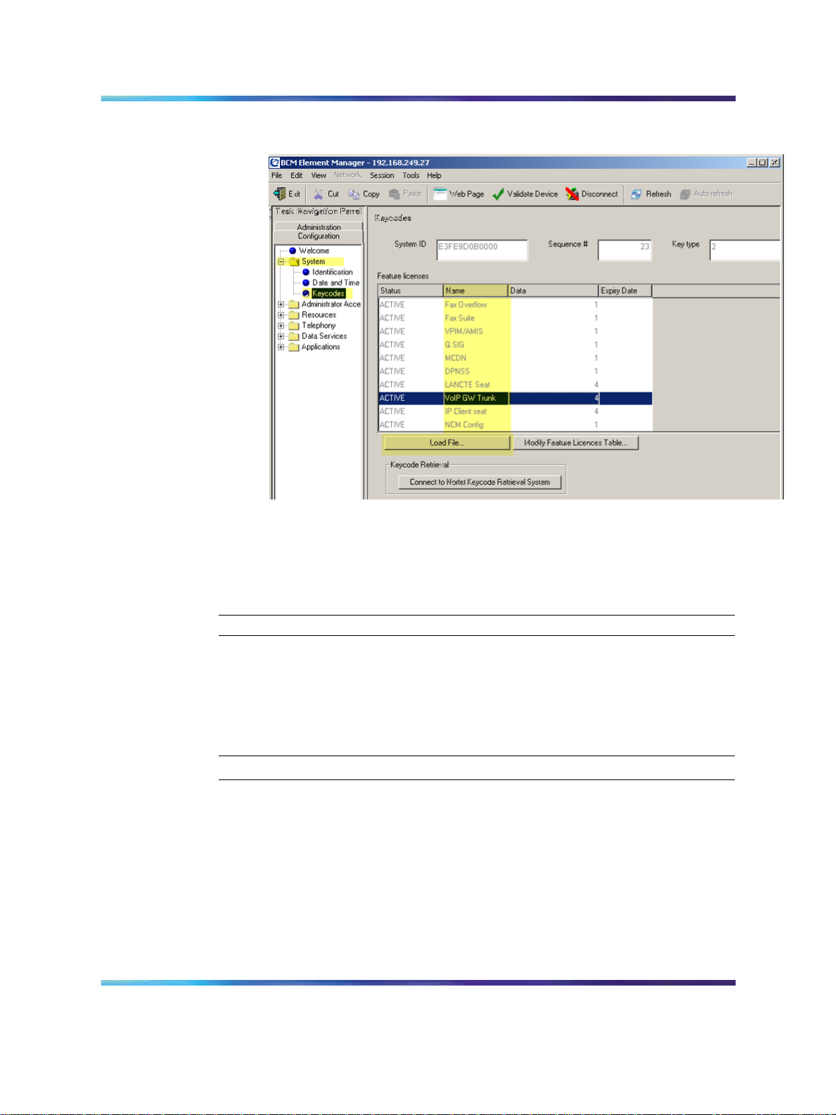
Select System > Keycodes.
See Figure 1 "Keycodes" (page 18).
Enterprise: Common
NN49000-303 01.01 Standard
Release 4.0, 3.7 29 June 2007
Page 18
18 BCM 200/400 Release 4.0 configuration
Figure 1 Keycodes
4
Load new Keycodes by loading a new keycode file or connecting to
Nortel’s Keycode Retrieval System (KRS).
For more information about keycodes and keycode retrieval, see
Keycode Installation Guide (NN40010-301).
—End—
Verifying system license and keycodes
Perform the following procedure to verify system license and keycodes.
Verifying system license and keycodes
Step Action
1
2
3
4
Log on to Element Manager.
In the Task Navigation Panel, select the Configuration tab.
Select System > Keycodes.
See Figure 1 "Keycodes" (page 18).
In the Name column, scroll down to VoIP GW Trunk. The number of
license keys you have are listed in the Data column.
Solution Integration Guide for Multisite Business Communications Manager Systems
Copyright © 2007, Nortel Networks
.
Enterprise: Common
NN49000-303 01.01 Standard
Release 4.0, 3.7 29 June 2007
Page 19
Configuring VoIP trunk media parameters 19
—End—
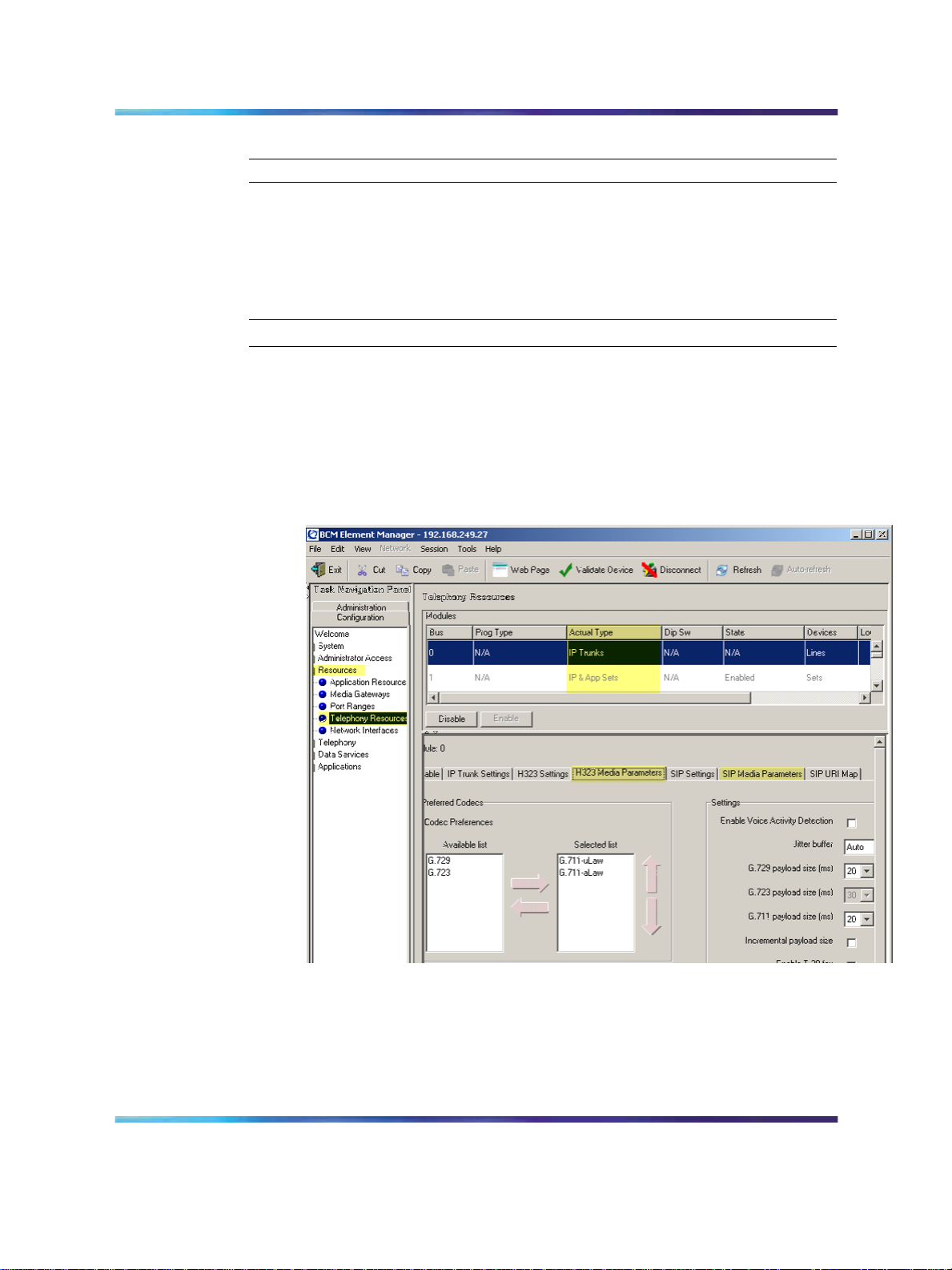
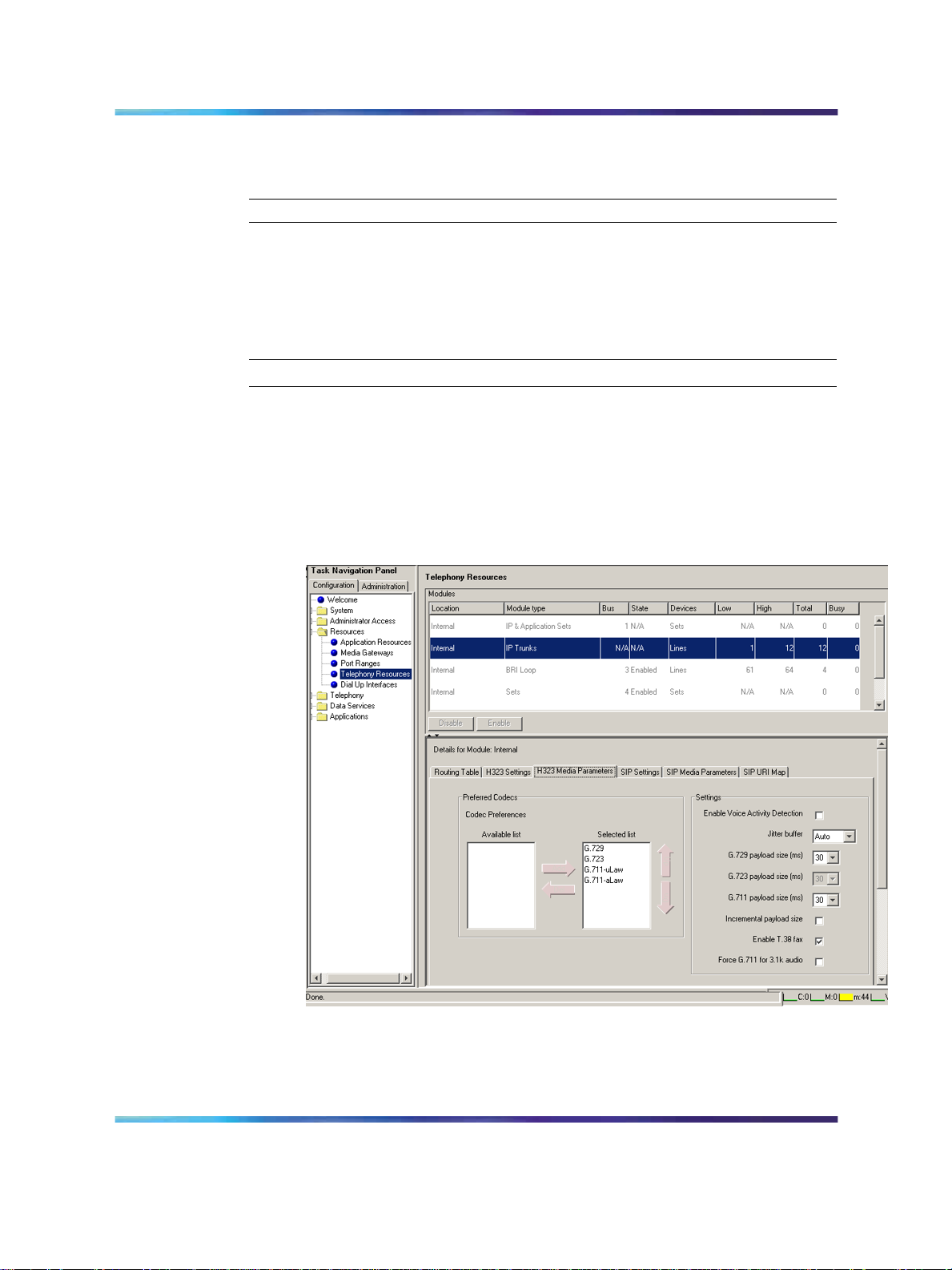
Configuring VoIP trunk media parameters
Perform the following procedure to configure VoIP trunk media parameters.
Configuring VoIP trunk media parameters
Step Action
1
Log on to Element Manager.
2 In the Task Navigation Panel, select the Configuration tab.
3
Select Resources > Telephony Resources.
See Figure 2 "Telephony Resources" (page 19).
Figure 2 Telephony Resources
4
5 Select the H.323 Media Parameters or SIP Media Parameters tab.
6
Solution Integration Guide for Multisite Business Communications Manager Systems
Copyright © 2007, Nortel Networks
.
In the Modules panel, select the line where the Actual Type column
is set to IP Trunks.
Enter the information that supports your system.
Enterprise: Common
NN49000-303 01.01 Standard
Release 4.0, 3.7 29 June 2007
Page 20

20 BCM 200/400 Release 4.0 configuration
Ensure that these settings are consistent with the other systems on
your network.
Refer to Table 4 "H.323 Media Parameters fields" (page 20) and
Table 5 "SIP Media Parameters fields" (page 21) for a description
of the parameters.
—End—
Table 4
H.323 Media Parameters fields
Field Value Description
Preferred Codecs
Enable Voice
Activity Detection
G.711 -uLaw
G.711 -aLaw
G.729
G.723
Add codecs to the Selected list and order them
in the order in which you want the system to
attempt to use them. The system attempts to use
the codecs in top-to-bottom sequence.
Performance note: Codecs on all networked
BCMs must be consistent to ensure the proper
functionality of interacting features such as
Transfer and Conference.
Systems running BCM Release 3.5 or later
allow codec negotiation and renegotiation to
accommodate inconsistencies in codec settings
over VoIP trunks.
<check box> Voice Activity Detection (VAD), also known
as silence suppression, identifies periods of
silence in a conversation and stops sending
IP speech packets during those periods. In
a typical telephone conversation, most of the
conversation is half-duplex, meaning that one
person is speaking while the other is listening. If
VAD is enabled, no voice packets are sent from
the listener end. This greatly reduces bandwidth
requirements. G.723.1 and G.729 support VAD.
G.711 does not support VAD.
Solution Integration Guide for Multisite Business Communications Manager Systems
Copyright © 2007, Nortel Networks
.
Performance note: VAD on all networked BCMs
and IPT systems must be consistent to ensure
functionality of features such as Transfer and
Conference. The Payload size on the IPT must
be set to 30ms.
Enterprise: Common
NN49000-303 01.01 Standard
Release 4.0, 3.7 29 June 2007
Page 21

Configuring VoIP trunk media parameters 21
Field Value Description
Jitter Buffer
Auto
Select the size of jitter buffer for your system.
None
Small
Medium
Large
G.729 payload size
(ms)
G.723 payload size
(ms)
G.711 payload size
10,20,30,40,50,60
30
10,20,30,40,50,60
Set the maximum required payload size, per
codec, for the VoIP calls sent over H.323 trunks.
Note: Payload size can also be set for Nortel
IP telephones. See
BCM 4.0 Telephony Device
Installation Guide (N0060609).
(ms)
Incremental
payload size
<check box> When enabled, the system advertises a variable
payload size (40, 30, 20, 10 ms).
Enable T.38 fax <check box> When enabled, the system supports T.38 fax
over IP.
Caution: Fax tones broadcast through a
telephone speaker may disrupt calls at other
telephones using VoIP trunks in the vicinity of
the fax machine. To minimize the possibility of
your VoIP calls being dropped due to fax tone
interference:
•
place the fax machine away from other
telephones
•
turn the fax machine’s speaker volume to the
lowest level, or off, if available
Force G.711 for 3.1k
Audio
<check box> When enabled, the system forces the VoIP trunk
to use the G.711 codec for 3.1k audio signals,
such as modem or TTY machines.
Note: You also can use this setting for fax
machines if T.38 fax is not enabled on the trunk.
Table 5
SIP Media Parameters fields
Field Value Description
Preferred Codecs
Solution Integration Guide for Multisite Business Communications Manager Systems
Copyright © 2007, Nortel Networks
.
G.711 -uLaw
G.711 -aLaw
G.729
Enterprise: Common
NN49000-303 01.01 Standard
Release 4.0, 3.7 29 June 2007
Add codecs to the Selected list and order them
in the order in which you want the system to
attempt to use them. The system attempts to use
the codecs in a top-to-bottom sequence.
Page 22

22 BCM 200/400 Release 4.0 configuration
Field Value Description
Enable Voice
Activity Detection
G.723
Performance note: Codecs on all networked
BCMs must be consistent to ensure the proper
functionality of interacting features such as
Transfer and Conference.
Systems running BCM Release 3.5 or later
allow codec negotiation and renegotiation to
accommodate inconsistencies in codec settings
over VoIP trunks.
<check box> Voice Activity Detection (VAD), also known
as silence suppression, identifies periods of
silence in a conversation and stops sending
IP speech packets during those periods. In
a typical telephone conversation, most of the
conversation is half-duplex, meaning that one
person is speaking while the other is listening. If
VAD is enabled, no voice packets are sent from
the listener end. This greatly reduces bandwidth
requirements. G.723.1 and G.729 support VAD.
G.711 does not support VAD.
Performance note: VAD on all networked BCMs
and IPT systems must be consistent to ensure
functionality of features such as Transfer and
Conference. The Payload size on the IPT must
be set to 30ms.
Jitter Buffer
G.729 payload size
(ms)
G.723 payload size
(ms)
G.711 payload size
(ms)
Enable T.38 fax
Solution Integration Guide for Multisite Business Communications Manager Systems
Copyright © 2007, Nortel Networks
.
Auto
Select the size of jitter buffer for your system.
None
Small
Medium
Large
10,20,30,40,50,60
Set the maximum required payload size, per
codec, for the VoIP calls sent over H.323 trunks.
30
Note: Payload size can also be set for Nortel
IP telephones. See BCM 4.0 Telephony Device
10,20,30,40,50,60
Installation Guide (N0060609).
<check box> When enabled, the system supports T.38 fax
over IP.
Caution: Fax tones broadcast through a
telephone speaker may disrupt calls at other
telephones using VoIP trunks in the vicinity of
Enterprise: Common
NN49000-303 01.01 Standard
Release 4.0, 3.7 29 June 2007
Page 23

Field Value Description
the fax machine. To minimize the possibility of
your VoIP calls being dropped due to fax tone
interference:
•
place the fax machine away from other
telephones
•
turn the fax machine’s speaker volume to the
lowest level, or off, if available
Configuring local Gateway parameters
Perform the following procedure to configure local Gateway parameters.
Configuring local Gateway parameters
Step Action
Configuring local Gateway parameters 23
1
2
Log on to Element Manager.
In the Task Navigation Panel, select the Configuration tab.
3 Select Resources > Telephony Resources.
4
In the Module Panel, select the line in which the Actual Type
column is set to IP Trunks.
See Figure 2 "Telephony Resources" (page 19).
5 Select the IP Trunk Settings tab and enter the information that
supports your system.
See Figure 3 "IP Trunk Settings" (page 24). Refer to Table 6 "IP
Trunk Settings fields" (page 24) for information about the IP Trunk
Settings fields.
Solution Integration Guide for Multisite Business Communications Manager Systems
Copyright © 2007, Nortel Networks
.
Enterprise: Common
NN49000-303 01.01 Standard
Release 4.0, 3.7 29 June 2007
Page 24
24 BCM 200/400 Release 4.0 configuration
Figure 3 IP Trunk Settings
Table 6
IP Trunk Settings fields
Field Value Description
Forward redirected
OLI
<check box> If enabled, the OLI of an internal telephone
is forwarded over the VoIP trunk when a call
is transferred to an external number over the
private VoIP network. If disabled, only the CLID
of the transferred call is forwarded.
Send name display
<check box> If enabled, the telephone name is sent with
outgoing calls to the network.
Remote capability
MWI
6
<check box> This setting must coordinate with the functionality
of the remote system hosting remote voice mail.
For H.323 VoIP trunks, select the H.323 Settings tab.
See Figure 4 "H.323 Settings" (page 25).
Solution Integration Guide for Multisite Business Communications Manager Systems
Copyright © 2007, Nortel Networks
.
Enterprise: Common
NN49000-303 01.01 Standard
Release 4.0, 3.7 29 June 2007
Page 25

Figure 4 H.323 Settings
Configuring local Gateway parameters 25
7
8
9
10
Solution Integration Guide for Multisite Business Communications Manager Systems
Copyright © 2007, Nortel Networks
.
When implementing your dialing plan, in the H.323 Settings tab,
select a value for Fall back to circuit-switched. This determines
how the system handles calls if the IP network cannot be used.
For Gateway protocol, select CSE.
Scroll down to Alias names and click Modify.
The Modify Call Signaling Settings page appears.
Enter the information that supports your system.
Applying the changes made to the Call Signaling Settings causes
all H.323 calls to be dropped. It is recommended that you make
changes to the Call Signaling Settings during off-peak hours or a
scheduled maintenance window.
Enterprise: Common
NN49000-303 01.01 Standard
Release 4.0, 3.7 29 June 2007
Page 26

26 BCM 200/400 Release 4.0 configuration
Refer to Table 7 "H.323 Call Signaling Settings fields" (page 26).
Table 7
H.323 Call Signaling Settings fields
Field Value Description
Call signaling
Call signaling port
Direct Call signaling information is passed directly
between H.323 endpoints. You must set up
remote Gateways.
Gatekeeper
Resolved
All call signaling occurs directly between H.323
endpoints. This means that the Gatekeeper
resolves the phone numbers into IP addresses,
but the Gatekeeper is not involved in call
signaling.
Gatekeeper Routed Gatekeeper Routed uses a Gatekeeper for call
setup and control. In this method, call signaling
is directed through the Gatekeeper.
Gatekeeper Routed
no RAS
Use this setting for a NetCentrex Gatekeeper.
With this setting, the system routes all calls
through the Gatekeeper but does not use any
of the Gatekeeper Registration and Admission
Services (RAS).
Choose this option if RAS is not enabled on the
NRS.
<port value> If VoIP applications are installed that require
nonstandard call signaling ports, enter the port
number here. Port number 0 means that the
system uses the first available port.
RAS port
Enable H245
tunneling
Primary Gatekeeper
IP
Backup Gatekeepe
r(s)
Solution Integration Guide for Multisite Business Communications Manager Systems
Copyright © 2007, Nortel Networks
.
The default port for call signaling is 1720.
<port value> If the VoIP application requires a nonstandard
RAS port, enter the port number here. Port
number 0 means that the system uses the first
available port.
<check box> Select this field to allow H.245 messages within
H.225. Restart the VoIP service for this feature
to take effect.
<IP address> Fill in this field only if the network is controlled
by a Gatekeeper. This is the IP address of the
primary Gatekeeper (TLAN IP address).
<IP address> NetCentrex Gatekeeper does not support RAS.
Any backup Gatekeepers must be entered in this
field. Gatekeepers that use RAS can provide a
list of backup Gatekeepers for the endpoint to
use in the event of a primary Gatekeeper failure.
Enterprise: Common
NN49000-303 01.01 Standard
Release 4.0, 3.7 29 June 2007
Page 27

Configuring local Gateway parameters 27
Field Value Description
Alias names
Registration TTL(s)
11
NAME:<alias name> Enter the alias names of the BCM required to
direct call signals to your system.
Note: The Alias name is case sensitive. It must
match the name configured in NRS.
<numeric value> Specifies the keep-alive interval.
For SIP trunks, select the SIP Settings tab.
See Figure 5 "SIP Settings" (page 27).
Figure 5 SIP Settings
12
Solution Integration Guide for Multisite Business Communications Manager Systems
Copyright © 2007, Nortel Networks
.
Enter the information that supports your system.
Enterprise: Common
NN49000-303 01.01 Standard
Release 4.0, 3.7 29 June 2007
Page 28

28 BCM 200/400 Release 4.0 configuration
Refer to Table 8 "SIP Settings fields" (page 28) for more information.
Table 8
SIP Settings fields
Field Value Description
Fallback to
circuit-switched
Domain Name
Call signaling port
Outgoing Transport
Proxy
Status
Disabled
Enabled-TDM
Enabled-All
<port value> If VoIP applications are installed that require
UDP
TCP
Read Only This field displays the current status of the
Defines how you want the system to handle calls
that the system fails to send over the VoIP trunk.
Enabled-TDM enables fallback for calls
originating on digital telephones. This is useful
if your IP telephones are connected remotely,
on the public side of the BCM network, because
PSTN fallback is unlikely to result in better quality
of service.
Type the domain name of the SIP network.
nonstandard call signaling ports, enter the port
number here. Port number 0 means that the
system uses the first available port.
If entered, all SIP calls originate to this address.
Gatekeeper.
—End—
Configuring VoIP lines
Voice over IP (VoIP)lines simulate traditional Central Office (CO) lines. VoIP
lines transmit data over an IP network rather than over physical lines.
Configuring VoIP lines
Step Action
1 Log on to Element Manager.
2
3
4
5
Solution Integration Guide for Multisite Business Communications Manager Systems
Copyright © 2007, Nortel Networks
.
In the Task Navigation Panel, select the Configuration tab.
Select Telephony > Lines > All Lines.
Highlight the individual line you wish to configure.
Select the Parameters tab.
See Figure 6 "VoIP lines" (page 29).
Enterprise: Common
NN49000-303 01.01 Standard
Release 4.0, 3.7 29 June 2007
Page 29

Figure 6 VoIP lines
Configuring VoIP lines 29
6
Configure the Parameters tab appropriately for your network.
Refer to Table 9 "VoIP line descriptions" (page 29) for configuration
information.
Table 9
VoIP line descriptions
Field Value Description
Line
Trunk Type VoIP Ensure that the trunk type is set to VoIP when
Control Set
Prime Set
001-060
Unique line number.
configuring VoIP lines.
Identify a DN if you are using this line with
scheduling. To change the DN, double-click the
Control Set DN.
For VoIP trunks, it is recommended that the
Control Set be set to None because these are
virtual trunks. Ensure that the VoIP trunk is
assigned to a line pool.
Use the Prime Set if you want the line to be
answered at another telephone when the line is
not answered at the target telephone. To change
the Prime set, double-click the Prime set DN.
Solution Integration Guide for Multisite Business Communications Manager Systems
Copyright © 2007, Nortel Networks
.
For VoIP trunks, it is recommended that the
Prime Set be set to None because these are
virtual trunks. Ensure that the VoIP trunk is
assigned to a line pool.
Enterprise: Common
NN49000-303 01.01 Standard
Release 4.0, 3.7 29 June 2007
Page 30

30 BCM 200/400 Release 4.0 configuration
Field Value Description
Name
Line Type
Identify the line in a meaningful way.
Defines how the line is used in relation to other
lines in the system.
Public If the line is to be shared among telephones, set
to Public.
DN:* If the line is assigned to only one telephone, set
to DN:*.
Pool [A to O] If you are using routing, put the line into line pool
(A to F).
If you are using line pools, configure the target
lines. If your system uses both H.323 and SIP
trunks, assign H.323 trunks to one pool and SIP
trunks to another.
Distinct Ring 2, 3, 4, or None For trunks assigned to line pools, set the Distinct
Ring pattern to None.
7
Select the Preferences tab.
See Figure 7 "Preferences" (page 30).
Figure 7 Preferences
8
Solution Integration Guide for Multisite Business Communications Manager Systems
Copyright © 2007, Nortel Networks
.
Configure the Preferences tab appropriately for your network.
Enterprise: Common
NN49000-303 01.01 Standard
Release 4.0, 3.7 29 June 2007
Page 31

Refer to Table 10 "Preferences fields" (page 31) for configuration
information.
Table 10
Preferences fields
Field Value Description
Configuring VoIP lines 31
Auto privacy
<check box> Defines whether one BCM user can select a line
in use at another telephone to join an existing
call. For more information, see BCM 4.0 Device
Configuration Guide (N0060600).
Full autohold
<check box> Enables or disables Full autohold. When
enabled, if a caller selects an idle line but does
not dial any digits, that line is automatically
placed on hold if the caller selects another line.
Change the default setting only if Full autohold is
required for a specific application.
Aux. ringer
<check box> If your system is equipped with an external ringer,
you can enable this setting so that this line rings
at the external ringer.
Distinct rings in use Read only Indicates whether a special ring is assigned.
9
Select the Restrictions tab.
See Figure 8 "Restrictions" (page 31).
Figure 8 Restrictions
10
Solution Integration Guide for Multisite Business Communications Manager Systems
Copyright © 2007, Nortel Networks
.
Configure the Restrictions tab appropriately for your network.
Enterprise: Common
NN49000-303 01.01 Standard
Release 4.0, 3.7 29 June 2007
Page 32

32 BCM 200/400 Release 4.0 configuration
Refer to Table 11 "Restrictions fields" (page 32) for configuration
information.
Table 11
Restrictions fields
Field Value Description
Use remote
package
Schedule
Line Restrictions Use Filter
Remote Restriction
s - Use Filter
11
< package #> If the line is used to receive external calls or
calls from other nodes on the private network,
ensure that you indicate a remote package that
provides only the availability that you want for
external callers. This attribute is typically used
for tandeming calls.
Default: Normal,
Night, Evening,
Lunch, Sched 4,
Sched 5, Sched 6
<00-99>
Enter the restriction filter number that applies to
each schedule. These settings control outgoing
calls.
<00-99>
Enter the restriction filter that applies to each
schedule. These settings provide call controls for
incoming calls over a private network or from a
remote user dialing in over PSTN.
Select the Assigned DNs tab.
See Figure 9 "Assigned DNs" (page 32).
Figure 9 Assigned DNs
Solution Integration Guide for Multisite Business Communications Manager Systems
Copyright © 2007, Nortel Networks
.
Enterprise: Common
NN49000-303 01.01 Standard
Release 4.0, 3.7 29 June 2007
Page 33

Configuring target lines 33
12
13
Edit the listed DNs or click Add to add a DN as required.
Enter the appropriate information for your network.
Refer to Table 12 "Assigned DNs fields" (page 33) for configuration
information.
Table 12
Assigned DNs fields
Field Value Description
DN
Appearance Type
Appearances
Caller ID Set
Vmsg Set
Ring Only
Appr&Ring
Appr Only
<check box> When enabled, displays caller ID for calls coming
<check box> When enabled, an indicator appears on the
Unique number
Select Appr Only or Appr&Ring if the telephone
has an available button. Otherwise select Ring
Only.
Target lines can have more than one appearance
to accommodate multiple calls. For telephones
that have these lines set to Ring Only, set to
None.
in over the target line.
telephone when a message is waiting from a
remote voice mail system. Check with your
system administrator for the system voice mail
setup before changing this parameter.
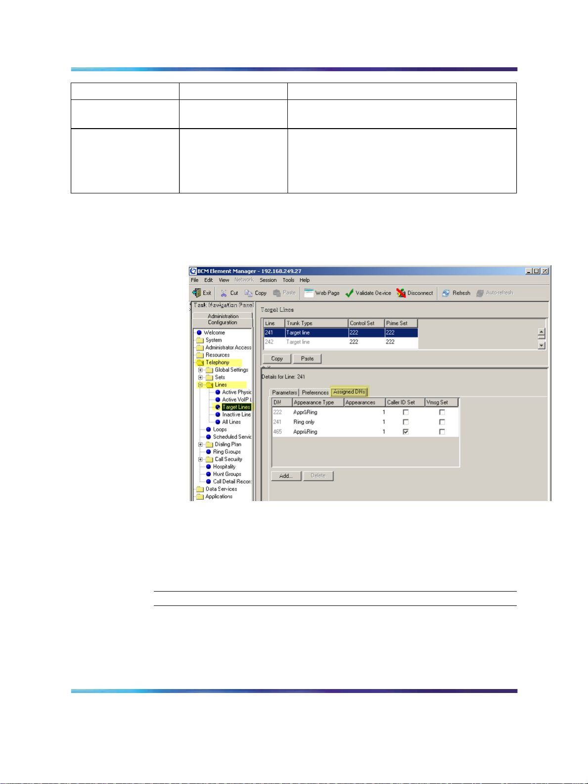
Configuring target lines
Targetlines are virtual communication paths between trunks and telephones
on the BCM system. They are incoming lines only and cannot be selected
for outgoing calls or networking applications.
Configuring target lines
Step Action
1
2
3
4
Solution Integration Guide for Multisite Business Communications Manager Systems
Copyright © 2007, Nortel Networks
.
Log on to Element Manager.
In the Task Navigation Panel, select the Configuration tab.
Select Telephony > Lines > Target Lines.
Highlight the individual line you wish to configure.
—End—
Enterprise: Common
NN49000-303 01.01 Standard
Release 4.0, 3.7 29 June 2007
Page 34

34 BCM 200/400 Release 4.0 configuration
5
Select the Parameters tab and enter the appropriate information for
your network.
See Figure 10 "Parameters" (page 34). Refer to Table 13
"Parameters fields" (page 34) for configuration information.
Figure 10 Parameters
Table 13
Parameters fields
Field Value Description
Name
Line Type
Pub. Received #
Public
DN:*:
Enter the name for the line, for example, Line241.
If the line is to be shared among telephones,
select Public. If the line is only assigned to one
telephone, select DN:*:.
Confirm the existing number or enter a public
received number (PSTN DID or PRI trunks) that
the system uses to identify calls from the public
network to the target line.
The public received number cannot be the same
as the beginning digits of a line pool access code
or destination code.
Solution Integration Guide for Multisite Business Communications Manager Systems
Copyright © 2007, Nortel Networks
.
Enterprise: Common
NN49000-303 01.01 Standard
Release 4.0, 3.7 29 June 2007
Page 35

Field Value Description
Configuring target lines 35
Priv. Received #
Distinct Ring
If private network trunks (PRI or VoIP trunks) are
configured, enter a private received number. The
private received number specifies the digits the
system uses to identify calls from the private
network to a target line.
This number is usually the same as the DN.
2, 3, 4, or None If you want this line to have a special ring, select
a ring pattern.
6
Select the Preferences tab and enter the appropriate information for
your network.
See Figure 11 "Preferences" (page 35). Refer toTable 14
"Preferences fields" (page 35) for configuration information.
Figure 11 Preferences
Table 14
Preferences fields
Field Value Description
Aux. ringer
<check box> If your system is equipped with an external ringer,
you can enable this setting so that this line rings
at the external ringer.
If Busy
Busy tone
To prime
To automatically direct calls to the prime
telephone, select To prime. Otherwise, select
Busy tone.
Distinct rings in use Read only
Solution Integration Guide for Multisite Business Communications Manager Systems
Copyright © 2007, Nortel Networks
.
Enterprise: Common
NN49000-303 01.01 Standard
Release 4.0, 3.7 29 June 2007
Page 36
36 BCM 200/400 Release 4.0 configuration
Field Value Description
Voice message
center
Redirect to
If the system is using a remote voice mail, select
the center configured with the contact number.
To automatically direct calls out of the system
to a specific telephone, such as a head office
answer attendant, enter that remote number
here. Ensure that you include the proper routing
information.
7
Select the Assigned DNs tab.
See Figure 12 "Assigned DNs" (page 36).
Figure 12 Assigned DNs
8
9
Solution Integration Guide for Multisite Business Communications Manager Systems
Copyright © 2007, Nortel Networks
.
Edit the listed DNs, or click Add to add a DN as required.
Enter the appropriate information for your network.
Refer to Table 12 "Assigned DNs fields" (page 33) for configuration
information.
—End—
Enterprise: Common
NN49000-303 01.01 Standard
Release 4.0, 3.7 29 June 2007
Page 37

BCM 200/400 Release 3.7 configuration
This chapter describes configuration procedures for the Business
Communications Manager (BCM) 200 and 400 Release 3.7 systems.
BCM 200/400 Release 3.7 configuration procedures
The sequence of BCM 200/400 Release 3.7 configuration procedures is as
follows:
•
"Verifying incoming VoIP trunks provisioning" (page 37)
• "Adding keycodes files" (page 38)
•
"Adding a functionality-specific keycode" (page 38)
•
"Configuring VoIP H.323 trunk media parameters" (page 39)
•
"Configuring VoIP SIP trunk media parameters" (page 40)
•
"Configuring H.323 local Gateway IP parameters" (page 41)
•
"Configuring SIP local Gateway IP parameters" (page 42)
37
•
"Configuring SIP subdomains" (page 43)
•
"Configuring remote H.323 Gateways" (page 44)
•
"Configuring remote SIP endpoints" (page 45)
•
"Configuring VoIP lines for outgoing calls" (page 46)
•
"Configuring target lines for incoming calls" (page 49)
•
"Configuring telephones to access outgoing VoIP lines" (page 50)
Verifying incoming VoIP trunks provisioning
Perform this procedure to verify that incoming VoIP trunks are provisioned.
Step Action
1
2
Solution Integration Guide for Multisite Business Communications Manager Systems
Copyright © 2007, Nortel Networks
.
Log on to the Unified Manager.
Select the BCM>System>Licensing heading.
The Licensing Setting page appears.
Enterprise: Common
NN49000-303 01.01 Standard
Release 4.0, 3.7 29 June 2007
Page 38

38 BCM 200/400 Release 3.7 configuration
3
4
Select the Applied Keycodes tab.
In the list of applied keycodes, check that there are sufficient VoIP
gateway ports.
Adding keycodes files
Perform the following procedure to add keycodes.
Step Action
1
2
3
4
5
Log on to the Unified Manager.
Select BCM>System>Licensing>Keycode Files.
The Keycode File Location Information page appears.
Enter the required information for the keycode file.
Select the Configuration tab.
Click Apply new Keycode File.
—End—
6
7
A message appears asking you to confirm. Click Yes.
When prompted, reboot the system to activate your new keycodes.
—End—
Adding a functionality-specific keycode
Perform the following procedure to verify the system license and keycodes.
Step Action
1
2
3
4
5
Log on to the Unified Manager.
Select the BCM>System>Licensing heading.
See figure from Adding keycodes files.
Select the Configuration tab.
Click Add a keycode.
The Keycode dialog box appears.
Enter a valid Keycode.
6
Solution Integration Guide for Multisite Business Communications Manager Systems
Copyright © 2007, Nortel Networks
.
Click Save.
Enterprise: Common
NN49000-303 01.01 Standard
Release 4.0, 3.7 29 June 2007
Page 39

Configuring VoIP H.323 trunk media parameters 39
—End—
Configuring VoIP H.323 trunk media parameters
Perform the following procedure to configure H.323 Gateway trunks.
Step Action
1
2
Log on to the Unified Manager.
Select the BCM>Services>IP telephony>IP trunks>H.323 trunks
heading.
The Local Gateway IP Interface page appears.
3
4
Select the Media Parameters tab.
Configure the parameters listed in the table below with the
appropriate values for your network.
Ensure that these settings are consistent with the other systems
on your network
Table 15
H.323 media parameters
Parameter Value
1st Preferred Codec None
2nd Preferred Codec None
3rd Preferred Codec None
G.729
G.723
G.711-uLaw
4th Preferred Codec None
G.711-aLaw
Silence Compression Enabled
Disabled
Jitter Buffer – Voice Auto
None
Small
Medium
Large
Solution Integration Guide for Multisite Business Communications Manager Systems
Copyright © 2007, Nortel Networks
.
Enterprise: Common
NN49000-303 01.01 Standard
Release 4.0, 3.7 29 June 2007
Page 40

40 BCM 200/400 Release 3.7 configuration
Parameter Value
T.38 Fax Support Enabled
Disabled
G.729 Payload Size (ms)
10, 20, 30, 40, 50, 60
G.723 Payload Size (ms)
G.729 Payload Size (ms)
Incremental Payload Size Enabled
30
10, 20, 30, 40, 50, 60
Disabled
—End—
Configuring VoIP SIP trunk media parameters
Perform the following procedure to configure SIP media parameters.
Step Action
1
2
3 Select the Media Parameters tab.
Log on to the Unified Manager.
Select the BCM>Services>IP Telephony> IP Trunks>SIP Trunks
heading.
The SIP Trunks Summary page appears.
4
Configure the parameters listed in the table below with the
appropriate values for your network.
Ensure that these settings are consistent with the other systems on
your network.
Table 16
SIP media parameters
Parameter Value
1st Preferred Codec None
2nd Preferred Codec None
3rd Preferred Codec None
Solution Integration Guide for Multisite Business Communications Manager Systems
Copyright © 2007, Nortel Networks
.
Enterprise: Common
NN49000-303 01.01 Standard
Release 4.0, 3.7 29 June 2007
G.729
G.723
G.711-uLaw
Page 41

Configuring H.323 local Gateway IP parameters 41
Parameter Value
4th Preferred Codec None
G.711-aLaw
Silence Compression Enabled
Disabled
Jitter Buffer – Voice Auto
None
Small
Medium
Large
—End—
Configuring H.323 local Gateway IP parameters
Perform the following procedure to configure local Gateway parameters.
Step Action
1
2
Log on to the Unified Manager.
Select the BCM>Services>IP Telephony>IP Trunks>H.323 Trunks
heading.
The Local Gateway IP Interface page appears.
3
4
Select Resources>Telephony Resources.
In the Local Gateway IP Interface section, configure the parameters
listed in the table below with the appropriate values for your network.
Table 17
H.323 local Gateway IP parameters
Parameter Value
Fallback to Circuit-Switched Enabled-All
Enabled-TDM-only
Disabled
Solution Integration Guide for Multisite Business Communications Manager Systems
Copyright © 2007, Nortel Networks
.
Enterprise: Common
NN49000-303 01.01 Standard
Release 4.0, 3.7 29 June 2007
Page 42

42 BCM 200/400 Release 3.7 configuration
Parameter Value
Call Signaling Direct
GatekeeperRouted
GatekeeperResolved
Gatekeeper RoutedNoRAS
Primary Gatekeeper IP
Backup Gatekeeper
Alias Names
Registration TTL (Seconds)
Gateway Protocol None
SL1
CSE
H245 Tunneling Enabled
Disabled
Call Signaling Port
RAS Port
Force G.711 for 3.1k Audio Enabled
Disabled
Forward Redirected OLI Enabled
Disabled
5
When implementing your dialing plan, in the H.323 Local Gateway
IP Interface tab, be sure to select a value for Fall back to
circuit-switched. This determines how the system handles calls if
the IP network cannot be used.
6
7
For Gateway protocol, select CSE.
Applying the changes made to the Call Signaling Settings causes
all H.323 calls to be dropped. It is recommended that you make
changes to the Call Signaling Settings during off-peak hours or a
scheduled maintenance window.
—End—
Configuring SIP local Gateway IP parameters
Perform the following procedure to configure SIP local Gateway IP
parameters.
Solution Integration Guide for Multisite Business Communications Manager Systems
Copyright © 2007, Nortel Networks
.
Enterprise: Common
NN49000-303 01.01 Standard
Release 4.0, 3.7 29 June 2007
Page 43

Step Action
Configuring SIP subdomains 43
1
2
Log on to the Unified Manager.
Select the BCM>Services>IP Telephony>IP Trunks>SIP Trunks
heading.
The Summary page appears.
3
Configure the parameters listed in the table below with the
appropriate values for your network.
Table 18
SIP local Gateway IP parameters
Parameter Value
Fallback to Circuit-Switched Enabled-All
Enabled-TDM-only
Disabled
SIP Domain
—End—
Configuring SIP subdomains
Perform the following procedure to configure SIP subdomains.
Step Action
1
2
3
4
Parameter Value
e.164 / National
e.164 / Subscriber
e.164 / Special
e.164 / Unknown
Log on to the Unified Manager.
Expand the BCM>Services>IP telephony>IP trunks>SIP trunks
heading.
The SIP Trunks Summary page appears.
Select the Dialing Sub-Domain tab.
Configure the parameters listed in the table below with the
appropriate values for your network.
Solution Integration Guide for Multisite Business Communications Manager Systems
Copyright © 2007, Nortel Networks
.
Enterprise: Common
NN49000-303 01.01 Standard
Release 4.0, 3.7 29 June 2007
Page 44

44 BCM 200/400 Release 3.7 configuration
Parameter Value
Private / UDP
Private / CDP
Private / Special
Private / Unknown
Unknown / Unknown
Configuring remote H.323 Gateways
Perform the following procedure to configure remote H.323 Gateways.
Step Action
—End—
1
2
Log on to the Unified Manager.
Expand the BCM>Services>IP telephony>IP trunks>H.323
trunks>Remote Gateway heading.
The Remote Gateway page appears.
3
4
5
Select Configuration.
Select Add Entry to add a new remote gateway.
Configure the parameters listed in the table below with the
appropriate values for your network.
Parameter Value
Name <alphanumeric>
Destination IP <IP address>
QoS Monitor Disabled
Enabled
Transmit Threshold 0.0 (bad) to 5.0 (excellent)
Receive Threshold 0.0 (bad) to 5.0 (excellent)
Solution Integration Guide for Multisite Business Communications Manager Systems
Copyright © 2007, Nortel Networks
.
Enterprise: Common
NN49000-303 01.01 Standard
Release 4.0, 3.7 29 June 2007
Page 45

Parameter Value
Gateway type BCM3.6
BCM3.5
BCM3.0
BCM2.5
CS1000
CS2000
IPT
NetMeeting
Norstar IP Gateway
Other
Gateway Protocol None
SL1
CSE
Destination Digits <numeric>
Configuring remote SIP endpoints 45
6
Click the Save button to save the remote gateway.
Configuring remote SIP endpoints
Perform the following procedure to configure remote SIP endpoints.
Step Action
1
2
3
4
Log on to the Unified Manager.
Expand the BCM>Services>IP telephony>IP trunks>SIP trunks
heading.
Select Address Book.
The Address Book page appears.
Select Configuration.
Can be the same as the destination code for
the route to the system.
—End—
5 Select Add Entry to add a new remote gateway.
Solution Integration Guide for Multisite Business Communications Manager Systems
Copyright © 2007, Nortel Networks
.
Enterprise: Common
NN49000-303 01.01 Standard
Release 4.0, 3.7 29 June 2007
Page 46

46 BCM 200/400 Release 3.7 configuration
6
Configure the parameters listed in the table below with the
appropriate values for your network.
Parameter Value
Name <alphanumeric>
Destination IP <IP address>
QoS Monitor Disabled
Enabled
Transmit Threshold 0.0 (bad) to 5.0 (excellent)
Receive Threshold 0.0 (bad) to 5.0 (excellent)
Destination Digits <numeric>
Can be the same as the destination code for
the route to the system.
7
Click the Save button to save the remote endpoint.
—End—
Configuring VoIP lines for outgoing calls
Perform the following procedure to configure VoIP lines for outgoing calls.
Step Action
1
2
3 In the All VoIP lines section, expand the Line you wish to configure
4
5
Table 19
General parameters
Parameter Value
Name
Control Set
Log on to the Unified Manager.
Expand the BCM>Services>Telephony Services>Lines>VoIP
Lines>All VoIP lines heading.
(for example, Line 001).
Select the General tab.
Configure the parameters listed in the table below with the
appropriate values for your network.
Use Remote Package
Solution Integration Guide for Multisite Business Communications Manager Systems
Copyright © 2007, Nortel Networks
.
Enterprise: Common
NN49000-303 01.01 Standard
Release 4.0, 3.7 29 June 2007
Page 47

Configuring VoIP lines for outgoing calls 47
6
Expand the Trunk/line data heading.
The Trunk/Line data page appears.
7
Configure the parameters listed in the table below with the
appropriate values for your network.
Note: The Line pool must belong to a line pool that contains the
same type of VoIP line.
If you want specific restrictions assigned to the line, enter the
information under the Restrictions heading.
Parameter Value Description
Line Type Public
Private to:
Pool {A to O }
Prime Set DN:
None
DN <defined DN #>
Distinct Ring None
Pattern 2
Pattern 3
Pattern 4
Auto Privacy N (No)
Y (Yes)
Use auxiliary ringer N (No)
Y (Yes)
Full autohold N (No)
Y (Yes)
Redirect to <dial string> Enter a dial string (including
routing code) to redirect the
line to an external telephone,
such as a call attendant on
another system. To stop
redirection, delete the dial
string and allow the record to
update
8
Expand the Restrictions>Line Restrictions heading.
Solution Integration Guide for Multisite Business Communications Manager Systems
Copyright © 2007, Nortel Networks
.
Enterprise: Common
NN49000-303 01.01 Standard
Release 4.0, 3.7 29 June 2007
Page 48

48 BCM 200/400 Release 3.7 configuration
9
Configure the local restrictions schedules for this line. Refer to the
table below for details.
Schedule
Normal Assign the filter to be used for
Night Assign the filter to be used for
Evening Assign the filter to be used for
Lunch Assign the filter to be used for
Sched 4 Assign the filter to be used for
Sched 5 Assign the filter to be used for
Sched 6 Assign the filter to be used for
10
Expand the Restrictions> Remote Restrictions heading.
Filter Description
Normal.
Night.
Evening.
Lunch.
Sched 4.
Sched 5.
Sched 6.
11
Configure the remote restrictions schedules for this line. Refer to
the table below for details.
Schedule
Normal Assign the filter to be used for
Night Assign the filter to be used for
Evening Assign the filter to be used for
Lunch Assign the filter to be used for
Sched 4 Assign the filter to be used for
Sched 5 Assign the filter to be used for
Sched 6 Assign the filter to be used for
Filter Description
Normal.
Night.
Evening.
Lunch.
Sched 4.
Sched 5.
Sched 6.
12 Repeat this procedure for all the outgoing lines you wish to configure.
Solution Integration Guide for Multisite Business Communications Manager Systems
Copyright © 2007, Nortel Networks
.
Enterprise: Common
NN49000-303 01.01 Standard
Release 4.0, 3.7 29 June 2007
Page 49

Configuring target lines for incoming calls 49
Note: Configuring SIP and H.323 trunks in the same pool may
result in unpredictable results because they do not support the
same level of service.
—End—
Configuring target lines for incoming calls
Perform the following procedure to configure telephones to access outgoing
VoIP lines.
Step Action
1
2
3
4
Log on to the Unified Manager.
Expand the BCM>Services>Lines>Target Lines heading.
Expand the target line to be configured.
Select the General tab.
5 Configure the parameters listed in the table below with the
appropriate values for your network.
Table 20
Target line parameters
Parameter Value
Name
Control Set
6
7
Select the Trunk/Line data tab.
Configure the parameters listed in the table below with the
appropriate values for your network.
Table 21
Target line parameters
Parameter Value
Trunk type
Line Type
If busy
Prime Set
Distinct ring in use
Solution Integration Guide for Multisite Business Communications Manager Systems
Copyright © 2007, Nortel Networks
.
Enterprise: Common
NN49000-303 01.01 Standard
Release 4.0, 3.7 29 June 2007
Page 50

50 BCM 200/400 Release 3.7 configuration
Parameter Value
Distinct ring
use Auxiliary ringer
redirect to
—End—
Configuring telephones to access outgoing VoIP lines
Perform the following procedure to configure telephones to access outgoing
VoIP lines.
Step Action
1
2
Log on to the Unified Manager.
Expand the BCM folder.
3 Expand the Services heading.
4
5
6
7
Expand the Telephony Services heading.
Expand the System DNs heading.
Expand the All System DNs or Active Set DNs heading.
Expand the DN you wish to configure to use VoIP trunking (for
example, DN 222).
8
9
10
Expand the Line Access heading.
Select Line pool access.
Click the Add button.
The Add Line Pool Access page appears.
11
12
Type the letter of the VoIP Line Pool to be used.
Click Save.
13
14
Solution Integration Guide for Multisite Business Communications Manager Systems
Copyright © 2007, Nortel Networks
.
To configure the line to access both H.323 and SIP Line pools,
repeat steps 11 and 12.
Repeat this procedure for all telephones you wish to configure to
access outside lines.
—End—
Enterprise: Common
NN49000-303 01.01 Standard
Release 4.0, 3.7 29 June 2007
Page 51

BCM50 configuration
This chapter describes configuration procedures for the Business
Communications Manager 50 (BCM50) system.
Element Manager as viewed on your system may differ slightly from the
screens shown in this chapter because you can customize the column
display in Element Manager.
BCM50 configuration procedures
The sequence of BCM50 configuration procedures is as follows:
•
"Configuring incoming VoIP trunks" (page 51)
•
"Verifying system license and keycodes" (page 52)
•
"Configuring VoIP trunk media parameters" (page 53)
•
"Configuring local Gateway parameters" (page 57)
•
"Configuring VoIP lines" (page 61)
51
•
"Configuring target lines" (page 65)
Configuring incoming VoIP trunks
Perform the following procedure to configure incoming VoIP trunks.
Configuring incoming VoIP trunks
Step Action
1
2
3 Select System > Keycodes.
Solution Integration Guide for Multisite Business Communications Manager Systems
Copyright © 2007, Nortel Networks
.
Log on to Element Manager.
In the Task Navigation Panel, select the Configuration tab.
See Figure 13 "Keycodes" (page 52).
Enterprise: Common
NN49000-303 01.01 Standard
Release 4.0, 3.7 29 June 2007
Page 52

52 BCM50 configuration
Figure 13 Keycodes
4
Load new Keycodes by loading a new keycode file or connecting to
Nortel’s Keycode Retrieval System (KRS).
For more information about keycodes and keycode retrieval, see
Keycode Installation Guide (NN40010-301).
—End—
Verifying system license and keycodes
Perform the following procedure to verify system license and keycodes.
Verifying system license and keycodes
Step Action
1
2
3
Log on to Element Manager.
In the Task Navigation Panel, select the Configuration tab.
Select System > Keycodes.
See Figure 13 "Keycodes" (page 52).
Solution Integration Guide for Multisite Business Communications Manager Systems
Copyright © 2007, Nortel Networks
.
Enterprise: Common
NN49000-303 01.01 Standard
Release 4.0, 3.7 29 June 2007
Page 53
Configuring VoIP trunk media parameters 53
4
In the Name column, scroll down to VoIP GW Trunk. The number of
license keys you have are listed in the Data column.
—End—
Configuring VoIP trunk media parameters
Perform the following procedure to configure VoIP trunk media parameters.
Configuring VoIP trunk media parameters
Step Action
1
2
3 Select Resources > Telephony Resources.
Log on to Element Manager.
In the Task Navigation Panel, select the Configuration tab.
See Figure 14 "Telephony Resources" (page 53).
Figure 14 Telephony Resources
4
5
Solution Integration Guide for Multisite Business Communications Manager Systems
Copyright © 2007, Nortel Networks
.
In the Modules panel, select the line where the Module Type
column is set to IP Trunks.
Select the H.323 Media Parameters or SIP Media Parameters tab.
Enterprise: Common
NN49000-303 01.01 Standard
Release 4.0, 3.7 29 June 2007
Page 54

54 BCM50 configuration
6
Enter the information that supports your system.
Ensure that these settings are consistent with the other systems on
your network.
Refer to Table 22 "H.323 Media Parameters fields" (page 54) and
Table 23 "SIP Media Parameters fields" (page 55) for a description
of the parameters.
—End—
Table 22
H.323 Media Parameters fields
Field Value Description
Preferred Codecs
G.711 -uLaw
G.711 -aLaw
G.729
G.723
Add codecs to the Selected list and order them
in the order in which you want the system to
attempt to use them. The system attempts to use
the codecs in top-to-bottom sequence.
Performance note: Codecs on all networked
BCMs must be consistent to ensure the proper
functionality of interacting features such as
Transfer and Conference.
Systems running BCM Release 3.5 or later
allow codec negotiation and renegotiation to
accommodate inconsistencies in codec settings
over VoIP trunks.
Enable Voice
Activity Detection
Solution Integration Guide for Multisite Business Communications Manager Systems
Copyright © 2007, Nortel Networks
.
<check box> Voice Activity Detection (VAD), also known
as silence suppression, identifies periods of
silence in a conversation and stops sending
IP speech packets during those periods. In
a typical telephone conversation, most of the
conversation is half-duplex, meaning that one
person is speaking while the other is listening. If
VAD is enabled, no voice packets are sent from
the listener end. This greatly reduces bandwidth
requirements. G.723.1 and G.729 support VAD.
G.711 does not support VAD.
Performance note: VAD on all networked BCMs
and IPT systems must be consistent to ensure
functionality of features such as Transfer and
Conference. The Payload size on the IPT must
be set to 30ms.
Enterprise: Common
NN49000-303 01.01 Standard
Release 4.0, 3.7 29 June 2007
Page 55

Configuring VoIP trunk media parameters 55
Field Value Description
Jitter buffer
Auto
Select the size of jitter buffer for your system.
None
Small
Medium
Large
G.729 payload size
(ms)
G.723 payload size
(ms)
G.711 payload size
10,20,30,40,50,60
30
10,20,30,40,50,60
Set the maximum required payload size, per
codec, for the VoIP calls sent over H.323 trunks.
Note: Payload size can also be set for Nortel
IP telephones. See
BCM 4.0 Telephony Device
Installation Guide (N0060609).
(ms)
Incremental
payload size
<check box> When enabled, the system advertises a variable
payload size (40, 30, 20, 10 ms).
Enable T.38 fax <check box> When enabled, the system supports T.38 fax
over IP.
Caution: Fax tones broadcast through a
telephone speaker may disrupt calls at other
telephones using VoIP trunks in the vicinity of
the fax machine. To minimize the possibility of
your VoIP calls being dropped due to fax tone
interference:
•
place the fax machine away from other
telephones
•
turn the fax machine’s speaker volume to the
lowest level, or off, if available
Force G.711 for 3.1k
audio
<check box> When enabled, the system forces the VoIP trunk
to use the G.711 codec for 3.1k audio signals,
such as modem or TTY machines.
Note: You also can use this setting for fax
machines if T.38 fax is not enabled on the trunk.
Table 23
SIP Media Parameters fields
Field Value Description
Preferred Codecs
Solution Integration Guide for Multisite Business Communications Manager Systems
Copyright © 2007, Nortel Networks
.
G.711 -uLaw
G.711 -aLaw
G.729
Enterprise: Common
NN49000-303 01.01 Standard
Release 4.0, 3.7 29 June 2007
Add codecs to the Selected list and order them
in the order in which you want the system to
attempt to use them. The system attempts to use
the codecs in a top-to-bottom sequence.
Page 56

56 BCM50 configuration
Field Value Description
Enable Voice
Activity Detection
G.723
Performance note: Codecs on all networked
BCMs must be consistent to ensure the proper
functionality of interacting features such as
Transfer and Conference.
Systems running BCM Release 3.5 or later
allow codec negotiation and renegotiation to
accommodate inconsistencies in codec settings
over VoIP trunks.
<check box> Voice Activity Detection (VAD), also known
as silence suppression, identifies periods of
silence in a conversation and stops sending
IP speech packets during those periods. In
a typical telephone conversation, most of the
conversation is half-duplex, meaning that one
person is speaking while the other is listening. If
VAD is enabled, no voice packets are sent from
the listener end. This greatly reduces bandwidth
requirements. G.723.1 and G.729 support VAD.
G.711 does not support VAD.
Performance note: VAD on all networked BCMs
and IPT systems must be consistent to ensure
functionality of features such as Transfer and
Conference. The Payload size on the IPT must
be set to 30ms.
Jitter buffer
G.729 payload size
(ms)
G.723 payload size
(ms)
G.711 payload size
(ms)
Enable T.38 fax
Solution Integration Guide for Multisite Business Communications Manager Systems
Copyright © 2007, Nortel Networks
.
Auto
Select the size of jitter buffer for your system.
None
Small
Medium
Large
10,20,30,40,50,60
Set the maximum required payload size, per
codec, for the VoIP calls sent over H.323 trunks.
30
Note: Payload size can also be set for Nortel
IP telephones. See BCM 4.0 Telephony Device
10,20,30,40,50,60
Installation Guide (N0060609).
<check box> When enabled, the system supports T.38 fax
over IP.
Caution: Fax tones broadcast through a
telephone speaker may disrupt calls at other
telephones using VoIP trunks in the vicinity of
Enterprise: Common
NN49000-303 01.01 Standard
Release 4.0, 3.7 29 June 2007
Page 57

Field Value Description
the fax machine. To minimize the possibility of
your VoIP calls being dropped due to fax tone
interference:
•
place the fax machine away from other
telephones
•
turn the fax machine’s speaker volume to the
lowest level, or off, if available
Configuring local Gateway parameters
Perform the following procedure to configure local Gateway parameters.
Configuring local Gateway parameters
Step Action
Configuring local Gateway parameters 57
1
2
Log on to Element Manager.
In the Task Navigation Panel, select the Configuration tab.
3 Select Resources > Telephony Resources.
4
In the Module Panel, select the line in which the Module type
column is set to IP Trunks.
See Figure 14 "Telephony Resources" (page 53).
5 For H.323 VoIP trunks, select the H.323 Settings tab.
See Figure 15 "H323 Settings" (page 58).
Solution Integration Guide for Multisite Business Communications Manager Systems
Copyright © 2007, Nortel Networks
.
Enterprise: Common
NN49000-303 01.01 Standard
Release 4.0, 3.7 29 June 2007
Page 58

58 BCM50 configuration
Figure 15 H323 Settings
6 When implementing your dialing plan, in the H323 Settings tab,
select a value for Fall back to circuit-switched. This determines
how the system handles calls if the IP network cannot be used.
7
For Gateway protocol, select CSE.
8 Scroll down to Alias names and click Modify.
The Modify Call Signaling Settings page appears.
9
Enter the information that supports your system.
Applying the changes made to the Call Signaling Settings causes
all H.323 calls to be dropped. It is recommended that you make
changes to the Call Signaling Settings during off-peak hours or a
scheduled maintenance window.
Solution Integration Guide for Multisite Business Communications Manager Systems
Copyright © 2007, Nortel Networks
.
Enterprise: Common
NN49000-303 01.01 Standard
Release 4.0, 3.7 29 June 2007
Page 59

Refer to Table 24 "H.323 Call Signaling Settings fields" (page 59).
Table 24
H.323 Call Signaling Settings fields
Field Value Description
Configuring local Gateway parameters 59
Call signaling
Call signaling Port
Direct Call signaling information is passed directly
between H.323 endpoints. You must set up
remote Gateways.
Gatekeeper
Resolved
All call signaling occurs directly between H.323
endpoints. This means that the Gatekeeper
resolves the phone numbers into IP addresses,
but the Gatekeeper is not involved in call
signaling.
Gatekeeper Routed Gatekeeper Routed uses a Gatekeeper for call
setup and control. In this method, call signaling
is directed through the Gatekeeper.
Gatekeeper Routed
no RAS
Use this setting for a NetCentrex Gatekeeper.
With this setting, the system routes all calls
through the Gatekeeper but does not use any
of the Gatekeeper Registration and Admission
Services (RAS).
Choose this option if RAS is not enabled on the
NRS.
<port value> If VoIP applications are installed that require
nonstandard call signaling ports, enter the port
number here. Port number 0 means that the
system uses the first available port.
RAS port
Enable H245
tunneling
Primary Gatekeeper
IP
Backup Gatekeepe
r(s)
Solution Integration Guide for Multisite Business Communications Manager Systems
Copyright © 2007, Nortel Networks
.
The default port for call signaling is 1720.
<port value> If the VoIP application requires a nonstandard
RAS port, enter the port number here. Port
number 0 means that the system uses the first
available port.
<check box> Select this field to allow H.245 messages within
H.225. Restart the VoIP service for this feature
to take effect.
<IP address> Fill in this field only if the network is controlled
by a Gatekeeper. This is the IP address of the
primary Gatekeeper (TLAN IP address).
<IP address> NetCentrex Gatekeeper does not support RAS.
Any backup Gatekeepers must be entered in this
field. Gatekeepers that use RAS can provide a
list of backup Gatekeepers for the endpoint to
use in the event of a primary Gatekeeper failure.
Enterprise: Common
NN49000-303 01.01 Standard
Release 4.0, 3.7 29 June 2007
Page 60

60 BCM50 configuration
Field Value Description
Alias names
Registration TTL(s)
10
NAME:<alias name> Enter the alias names of the BCM required to
direct call signals to your system.
Note: The Alias name is case sensitive. It must
match the name configured in NRS.
<numeric value> Specifies the keep-alive interval.
For SIP trunks, select the SIP Settings tab.
See Figure 16 "SIP Settings" (page 60).
Figure 16 SIP Settings
11
Solution Integration Guide for Multisite Business Communications Manager Systems
Copyright © 2007, Nortel Networks
.
Enter the information that supports your system.
Enterprise: Common
NN49000-303 01.01 Standard
Release 4.0, 3.7 29 June 2007
Page 61

Referto Table 25 "SIP Settings fields" (page 61) formore information.
Table 25
SIP Settings fields
Field Value Description
Configuring VoIP lines 61
Fallback to
circuit-switched
Domain Name
Call signaling port
Outgoing Transport
Proxy
Status
Disabled
Enabled-TDM
Enabled-All
<port value> If VoIP applications are installed that require
UDP
TCP
Read Only This field displays the current status of the
Defines how you want the system to handle calls
that the system fails to send over the VoIP trunk.
Enabled-TDM enables fallback for calls
originating on digital telephones. This is useful
if your IP telephones are connected remotely,
on the public side of the BCM network, because
PSTN fallback is unlikely to result in better quality
of service.
Type the domain name of the SIP network.
nonstandard call signaling ports, enter the port
number here. Port number 0 means that the
system uses the first available port.
If entered, all SIP calls originate to this address.
Gatekeeper.
—End—
Configuring VoIP lines
Voice over IP (VoIP)lines simulate traditional Central Office (CO) lines. VoIP
lines transmit data over an IP network rather than over physical lines.
Configuring VoIP lines
Step Action
1 Log on to Element Manager.
2
3
4
5
Solution Integration Guide for Multisite Business Communications Manager Systems
Copyright © 2007, Nortel Networks
.
In the Task Navigation Panel, select the Configuration tab.
Select Telephony > Lines > All Lines.
Highlight the individual line you wish to configure.
Select the Preferences tab.
See Figure 17 "Preferences" (page 62).
Enterprise: Common
NN49000-303 01.01 Standard
Release 4.0, 3.7 29 June 2007
Page 62

62 BCM50 configuration
Figure 17 Preferences
6
Configure the Preferences tab appropriately for your network.
Refer to Table 26 "Preferences fields" (page 62) for configuration
information.
Table 26
Preferences fields
Field Value Description
Aux. ringer
<check box> If your system is equipped with an external ringer,
you can enable this setting so that this line rings
at the external ringer.
Distinct rings in use
7
Read only Indicates whether a special ring is assigned.
Select the Restrictions tab.
See Figure 18 "Restrictions" (page 63).
Solution Integration Guide for Multisite Business Communications Manager Systems
Copyright © 2007, Nortel Networks
.
Enterprise: Common
NN49000-303 01.01 Standard
Release 4.0, 3.7 29 June 2007
Page 63

Figure 18 Restrictions
Configuring VoIP lines 63
8
Configure the Restrictions tab appropriately for your network.
Refer to Table 27 "Restrictions fields" (page 63) for configuration
information.
Table 27
Restrictions fields
Field Value Description
Use remote
package
Schedule
Line Restrictions Use Filter
Remote Restriction
s - Use Filter
< package #> If the line is used to receive external calls or
calls from other nodes on the private network,
ensure that you indicate a remote package that
provides only the availability that you want for
external callers. This attribute is typically used
for tandeming calls.
Default: Normal,
Night, Evening,
Lunch, Sched 4,
Sched 5, Sched 6
<00-99>
Enter the restriction filter number that applies to
each schedule. These settings control outgoing
calls.
<00-99>
Enter the restriction filter that applies to each
schedule. These settings provide call controls for
incoming calls over a private network or from a
remote user dialing in over PSTN.
Solution Integration Guide for Multisite Business Communications Manager Systems
Copyright © 2007, Nortel Networks
.
Enterprise: Common
NN49000-303 01.01 Standard
Release 4.0, 3.7 29 June 2007
Page 64

64 BCM50 configuration
9
10
11
In the Task Navigation Panel, in the Configuration tab, select
Telephony > Sets > All DNs.
Highlight the individual line you wish to configure.
Select the Line Assignment tab.
See Figure 19 "Line Assignment" (page 64).
Figure 19 Line Assignment
12
13
Edit the listed DNs, or click Add to add a DN as required.
Enter the appropriate information for your network.
Refer to Table 28 "Assigned DNs fields" (page 64) for configuration
information.
Table 28
Assigned DNs fields
Field Value Description
DN
Appearance Type
Appearances
Solution Integration Guide for Multisite Business Communications Manager Systems
Copyright © 2007, Nortel Networks
.
Ring only
Appr&Ring
Appr only
Enterprise: Common
NN49000-303 01.01 Standard
Release 4.0, 3.7 29 June 2007
Unique number
Select Appr Only or Appr&Ring if the telephone
has an available button. Otherwise select Ring
Only.
Target lines can have more than one appearance
to accommodate multiple calls. For telephones
that have these lines set to Ring Only, set to
None.
Page 65

Field Value Description
Configuring target lines 65
Caller ID Set
Vmsg Set
<check box> When enabled, displays caller ID for calls coming
<check box> When enabled, an indicator appears on the
Configuring target lines
Target lines are virtual communication paths between trunks and telephones
on the BCM system. They are incoming lines only and cannot be selected
for outgoing calls or networking applications.
Configuring target lines
Step Action
1
Log on to Element Manager.
in over the target line.
telephone when a message is waiting from a
remote voice mail system. Check with your
system administrator for the system voice mail
setup before changing this parameter.
—End—
2
3
4
5
In the Task Navigation Panel, select the Configuration tab.
Select Telephony > Lines > Target Lines.
Highlight the individual line you wish to configure.
Select the Preferences tab and enter the appropriate information for
your network.
See Figure 20 "Preferences" (page 66).
Refer toTable 29 "Preferences fields" (page 66) for configuration
information.
Solution Integration Guide for Multisite Business Communications Manager Systems
Copyright © 2007, Nortel Networks
.
Enterprise: Common
NN49000-303 01.01 Standard
Release 4.0, 3.7 29 June 2007
Page 66

66 BCM50 configuration
Table 29
Preferences fields
Figure 20 Preferences
Field Value Description
Aux. ringer
<check box> If your system is equipped with an external ringer,
you can enable this setting so that this line rings
at the external ringer.
If Busy
Distinct rings in use
Voice message
center
Redirect to
Busy tone
To prime
Read only
To automatically direct calls to the prime
telephone, select To prime. Otherwise, select
Busy tone.
If the system is using a remote voice mail, select
the center configured with the contact number.
To automatically direct calls out of the system
to a specific telephone, such as a head office
answer attendant, enter that remote number
here. Ensure that you include the proper routing
information.
6
Select the Assigned DNs tab.
See Figure 21 "Assigned DNs" (page 67).
Solution Integration Guide for Multisite Business Communications Manager Systems
Copyright © 2007, Nortel Networks
.
Enterprise: Common
NN49000-303 01.01 Standard
Release 4.0, 3.7 29 June 2007
Page 67

Figure 21 Assigned DNs
Configuring target lines 67
7
8
Edit the listed DNs, or click Add to add a DN as required.
Enter the appropriate information for your network.
Refer to Table 12 "Assigned DNs fields" (page 33) for configuration
information.
—End—
Solution Integration Guide for Multisite Business Communications Manager Systems
Copyright © 2007, Nortel Networks
.
Enterprise: Common
NN49000-303 01.01 Standard
Release 4.0, 3.7 29 June 2007
Page 68

68 BCM50 configuration
Solution Integration Guide for Multisite Business Communications Manager Systems
Copyright © 2007, Nortel Networks
.
Enterprise: Common
NN49000-303 01.01 Standard
Release 4.0, 3.7 29 June 2007
Page 69

Page 70

Enterprise: Common
Solution Integration Guide for Multisite Business Communications
Manager Systems
Copyright © 2007, Nortel Networks
All Rights Reserved.
Publication: NN49000-303
Document status: Standard
Document version: 01.01
Document date: 29 June 2007
To provide feedback or report a problem in this document, go to
ww.nortel.com/documentfeedback.
w
The information in this document is subject to change without notice. The statements, configurations, technical data, and
recommendations in this document are believed to be accurate and reliable, but are presented without express or implied
warranty. Users must take full responsibility for their applications of any products specified in this document. The information in
this document is proprietary to Nortel Networks.
Nortel, the Nortel logo and the Globemark are trademarks of Nortel Networks.
Microsoft, MS, MS-DOS, Windows, and Windows NT are registered trademarks of Microsoft Corporation.
All other trademarks and registered trademarks are the property of their respective owners.
Sourced in Canada.
 Loading...