

Page 1

Configuring MPOA and NHRP Services
BayRS Version 13.20
Site Manager Software Version 7.20
BCC Version 4.20
Part No. 305861-A Rev 00
April 1999
Page 2

Bay Networks, Inc.
4401 Great America Parkway
Santa Clara, CA 95054
Copyright © 1999 Bay Networks, Inc.
All rights reserved. Printed in the USA. April 1999.
The information in this document is subject to change without notice. The statements, configurations, technical data,
and recommendations in this document are believed to be accurate and reliable, but are presented without express or
implied warranty. Users must take full responsibility for their app lica tio ns o f any products specif i ed in th is d ocume nt .
The information in this document is proprietary to Bay Networks, Inc.
The software described in this document is furnished under a license agreement and may only be used in accordance
with the terms of that license. A summary of the Software License is included in this document.
Trademarks
AN, BCN, BLN, BN, and Bay Networks are registered trademarks and Advanced Remote Node, ANH, ARN, ASN,
BayRS, BCC, System 5000, and the Bay Networks logo are trademarks of Bay Networks, Inc.
All other trademarks and registered trademarks are t he property of their respective owners.
Restricted Rights Legend
Use, duplication, or disclosure by the United States Government is subject to restrictions as set forth in subparagraph
(c)(1)(ii) of the Rights in Technical Data and Computer So ftware clause at DFARS 252.227-7013.
Notwithstanding any other license agreement that may pertain to, or accompany the delivery of, this computer
software, the rights of the United States Government regarding its use, reproduction, and disclosure are as set forth in
the Commercial Computer Software-Restricted Rights cl ause at FAR 52.227-19.
Statement of Conditions
In the interest of improving internal design, operational function, and/or reliability, Bay Networks, Inc. reserves the
right to make changes to the pr oducts described in this document without notice.
Bay Networks, Inc. does not assume any liability that may occur due to the use or application of the product(s) or
circuit layout(s) described herein.
Portions of the code in this software product may be Copyright © 1988, Regents of the University of California. All
rights reserved. Redistribution and use in source and binary forms of such portions are permitted, provided that the
above copyright notice and this paragraph are duplicated in all such forms and that any documentation, advertising
materials, and other materials related to such distribution and use acknowledge that su ch portions of the software were
developed by the University of California, Berkeley. The name of the University may not be used to endorse or
promote products derived from such portions of the software without specific prior written permission.
SUCH PORTIONS OF THE SOFTWARE ARE PROVIDED “AS IS” AND WITHOUT ANY EXPRESS OR
IMPLIED WARRANTIES, INCLUDING, WITHOUT LIMITATION, THE IMPLIED WARRANTIES OF
MERCHANTABILITY AND FITNESS FOR A PARTICULAR PURPOSE.
In addition, the program and information contained herein are licensed only pursuant to a license agreement that
contains restrictions on use and disclosure (that may incorporate by reference certain limitations and notices imposed
by third parties).
ii
305861-A Rev 00
Page 3

Bay Networks, Inc. Software License Agreement
NOTICE: Please carefully read this license agre ement before copying or using the accompanying software or
installing the hardware unit with pre-enabled software (each of which is referred to as “Software” in this Agreement).
BY COPYING OR USING THE SOFTWARE, YOU ACCEPT ALL OF THE TERMS AND CONDITIONS OF
THIS LICENSE AGREEMENT. THE TERMS EXPRESSED IN THIS AGREEMENT ARE THE ONLY TERMS
UNDER WHICH BAY NETWORKS WILL PERMIT YOU TO USE THE SOFTWARE. If you do not accept these
terms and conditions, return the product, unused and in the original shipping container, within 30 days of purchase to
obtain a credit for the full purchase price.
1. License Grant. Bay Networks, Inc. (“Bay Networks”) grants the end user of the Software (“Licensee”) a personal,
nonexclusive, nontransferable license: a) to use the Software either on a single computer or, if applicable, on a single
authorized device identified by host ID, for which it was originally acquired; b) to copy the Software solely for backup
purposes in support of authorized use of the Software; and c) to use and copy the associated user manual solely i n
support of authorized use of the Software by Licensee. This license applies to the Software only and does not extend
to Bay Networks Agent software or other Bay Networks software products. Bay Networks Agent software or other
Bay Networks software products are licensed for use under the terms of the applicable Bay Networks, Inc. Software
License Agreement that accomp anies such software and upon payment by the end user of the applicable license fees
for such software.
2. Restrictions on use; reservation of rights. The Software and user manuals are protected under copyright laws.
Bay Networks and/or it s licensors retain all title and ownership in both the Software and user manuals, including any
revisions made by Bay Networks or its licensors. The copyright notice must be reproduced and included with any
copy of any portion of the Software or user manuals. Licensee may not modify, translate, decompile, disassemble, use
for any competitiv e analysis, re v erse engineer , distrib ute, or create deriv ati ve works from the Softwa re or user manuals
or any copy, in whole or in part. Except as expressly pr ovided i n t hi s Agreement, Licensee may not copy or transfer
the Software or user manuals, in whole or in part. The Soft ware and user manuals embody Bay Networks’ and its
licensors’ confidential and proprietary intellectual property. Licensee shall not sublicense, assign, or otherwise
disclose to any third party the Software, or any information about the operation, design, performance, or
implementation of the Software and user manuals that is confidential to Bay Networks and its licensors; however,
Licensee may grant permission to its consultants, subcontractors, a nd agents to use the Softw are at Licensee’s facility,
provided they have agreed to use the Software only in accordance with the terms of this license.
3. Limited warranty. Bay Netw o r ks wa r ra nts ea c h item of So ft ware, as delivered by Bay Net works and properly
installed and operated on Bay Networks hardware or other equipment it is originally licensed for, to function
substantially as described in its accompanying user m anual during its warranty period , which begins on the date
Software is first shipped to Licensee. If an y item of S oftware f ails to so function d uring its w arranty period, as the sole
remedy Bay Networks will at its discretion provide a suitable fix, patch, or workaround for the problem that may be
included in a future Software release. Bay Network s fur ther w arra nts to Licen see that the medi a on which the
Software is provided will be free from defec ts in materials and wo rkman ship under no rmal use for a peri od of 90 da ys
from the date Software is first shipped to Licensee. Bay Networks will replace defective media at no charge if it is
returned to Bay Netw orks during the warran ty perio d alon g with proof of the date of shipment . This war ranty do es not
apply if the media has been dam aged as a resul t of acci dent, misuse , or ab use. The Licen see assumes all re sponsibilit y
for selection of the Software to achieve Licensee’s intended results and for the installation, use, and results obtained
from the Software. Bay Networks does not warrant a) that the functions contained in the software will meet the
Licensee’ s requireme nts, b) that the Software will operate in the hardware or software combinations that th e Licens ee
may select, c) that the operation of the Softw a re will be uninterru pte d or error free, or d) that all defec ts in the
operation of the Software will be corrected. Bay Networks is not obligated to remedy any Software defect that cannot
be reproduced with the latest Software release. These warranties do not apply to the So ftw are if i t has been (i) altered,
except by Bay Networks or in accordance with its instructions; (ii) used in conjunction with another vendor’s product,
resulting in the defect; or (iii) damaged by improper environment, abuse, misuse, accident, or negligence. THE
FOREGOING WARRANTIES AND LIMITATIONS ARE EXCLUSIVE REMEDIES AND ARE IN LIEU OF ALL
OTHER WARRANTIES EXPRESS OR IMPLIED, INCLUDING W ITHOUT LIMITATION ANY W ARRANTY OF
MERCHANTABILITY OR FITNESS FOR A PARTICULAR PURPOSE. Licensee is responsible for the security of
305861-A Rev 00
iii
Page 4

its own data and information and for maintaining adequate procedures apart from the Software to reconstruct lost or
altered files, data, or programs.
4. Limitation of liability. IN NO EVENT WILL BAY NETWORKS OR ITS LICENSORS BE LIABLE FOR ANY
COST OF SUBSTITUTE PROCUREMENT; SPECIAL, INDIRECT, INCIDENTAL, OR CONSEQUENTIAL
DAMAGES; OR ANY DAMAGES RESULTING FROM INACCURATE OR LOST DATA OR LOSS OF USE OR
PROFITS ARISING OUT OF OR IN CONNECTION WITH THE PERFORMANCE OF THE SOFTWARE, EVEN
IF BAY NETWORKS HAS BEEN ADVISED OF THE POSSIBILITY OF SUCH DAMAGES. IN NO EVENT
SHALL THE LIABILITY OF BAY NETWORKS RELATING TO THE SOFTWARE OR THIS AGREEMENT
EXCEED THE PRICE PAID TO BAY NETWORKS FOR THE SOFTWARE LICENSE.
5. Government Licensees. This provision applies to a ll Softwa re and docum entation acquired d irectly or i ndirectly by
or on behalf of the United States Government. The Software and documentation are commercial products, licensed on
the open market at market prices, and were developed entirely at private expense and without th e use of any U.S.
Government funds. The license to the U.S. Government is granted only with restricted rights, and use, duplication, or
disclosure by the U.S. Government is subject to the restrictions set forth in subparagraph (c)(1) of the Commercial
Computer Software––Restricte d Rig hts cla u se o f FAR 52.227-19 and the limitations se t o ut in this license for civilian
agencies, and subparagraph (c)(1)(ii) of the Rights in Technical Data and Computer Software clause of DFARS
252.227-7013, for agencies of t he Department of Defense or their successors, whichever is applicable.
6. Use of Software in the European Community. This provision applies to all Software acquired for use within the
European Community. If Licensee uses the Software within a country in the European Community, the Software
Directive enacted by the Council of European Communities Directive dated 14 May, 1991, will apply to the
examination of the Software to facilitate interoperability. Licensee agrees to notify Bay Networks of any such
intended examination of the Software and may procure support and assistance from Bay Networks.
7. Term and termination. This license is effecti ve until terminated; however, all of the restrictions with respect to
Bay Networks’ copyright in the Software and user manuals will cease being effective at the date of expiration of the
Bay Networks copyright; those restrictions relating to use and disclosure of Bay Networks’ confidential information
shall continue in effect. Licensee may terminate this license at any time. The license will automatically terminate if
Licensee fails to comply with any of the terms and conditions of the license. Upon termination for any reason,
Licensee will immediately destroy or return to Bay Networks the Software, user manuals, and all copies. Bay
Networks is not liable to Licensee for damages in any form solely by reason of the termination of this license.
8. Export and Re-export. Licensee agrees not to export, directly or indirectly, the Software or related technical data
or information without first obtaining any required export licenses or other governmental approvals. Without limiting
the foregoing, Licensee, on behalf of itself and its subsidiaries and affiliates, agrees that it will not, without first
obtaining all export licenses and approvals required by the U.S. Government: (i) export, re-export, transfer, or divert
any such Software or technical data, or any direct product thereof, to any country to which such exports or re-exports
are restricte d or em b argoed under United States export cont rol laws and re gu la tio ns , or to any national or re sident of
such restricted or embargoed countries; or (ii) provide the Software or related technical data or information to any
military end user or for any military end use, including the design, development, or production of any chemical,
nuclear, or biological weapons.
9. General. If any provision of this Agreement is held to be invalid or unenf orceable by a court of competent
jurisdiction, the remainder of the provisions of this Agreement shall remain in full force and effect. This Agreement
will be governed by the laws of the state of California.
Should you have any questions concerning this Agreement, contact Bay Networks, Inc., 4401 Great America Parkway,
P.O. Bo x 58185, Santa Clara, California 9505 4- 8185.
LICENSEE ACKNOWLEDGES THAT LICENSEE HAS READ THIS AGREEMENT, UNDERSTANDS IT, AND
AGREES TO BE BOUND BY ITS TERMS AND CONDITIONS. LICENSEE FURTHER AGREES THAT THIS
AGREEMENT IS THE ENTIRE AND EXCLUSIVE AGREEMENT BETWEEN BAY NETWORKS AND
LICENSEE, WHICH SUPERSEDES ALL PRIOR ORAL AND WRITTEN AGREEMENTS AND
COMMUNICATIONS BETWEEN THE PARTIES PERTAINING TO THE SUBJECT MATTER OF THIS
AGREEMENT. NO DIFFERENT OR ADDITIONAL TERMS WILL BE ENFORCEABLE AGAINST BAY
NETWORKS UNLESS BAY NETWORKS GIVES ITS EXPRESS WRITTEN CONSENT, INCLUDING AN
EXPRESS WAIVER OF THE TERMS OF THIS AGREEMENT
iv
305861-A Rev 00
Page 5

Contents
Preface
Before You Begin .............................................................................................................xiii
Text Conventions .............................................................................................................xiv
Acronyms ........................... .......................... .......................... ......................... .................xvi
Bay Networks Technical Publications ............................................................................xviii
How to Get Help ............................................................................................................xviii
Chapter 1
Understanding MPOA and NHRP
ATM General Information ................................................................................................1-1
Multi-Protocol over ATM ..................................................................................................1-2
MPOA Logical Components .....................................................................................1-3
MPOA Basic Elements .............................................................................................1-4
Establishing a Network Cut-Through .... ...... ....................................... ...... ....... ...... ...1-5
NHRP .............................................................................................................................1-7
For More Information ......................................................................................................1-8
Where to Go Next ...........................................................................................................1-9
Chapter 2
Starting MPOA and NHRP Services
Starting Configuration Tools ...........................................................................................2-1
Starting the MPOA Server ..............................................................................................2-2
Creating an MPOA Service Record .........................................................................2-2
Adding an MPOA Server ..........................................................................................2-4
Starting NHRP on an ATM LEC, PVC, or Classical IP Service ......................................2-5
Starting NHRP on an ATM LEC Service ..................................................................2-6
Starting NHRP on an ATM PVC Service ................................................................2-11
Starting NHRP on an ATM Classical IP (RFC 1577 SVC) Service ........................2-14
Where to Go Next .........................................................................................................2-16
305861-A Rev 00
v
Page 6

Chapter 3
Customizing MPOA Services
Disabling and Reenabling an MPOA Service .................................................................3-2
Setting the MPS Address Generating Mode ...................................................................3-3
Specifying an MPS Control ATM Address ......................................................................3-5
Network Prefix ..........................................................................................................3-5
User Suffix ................................................................................................................3-6
Disabling and Reenabling MPOA Servers ............................. ...... ...... ....... ...... ....... ...... ...3-8
Specifying the MPS Configuration Mode ......................................................................3-10
Specifying a LECS ATM Address .................................................................................3-11
Network Prefix ........................................................................................................3-12
User Suffix ..............................................................................................................3-12
Configuring a Unique Selector Byte for an MPS Address ............................................3-14
Defining MPS Timer Values ..........................................................................................3-16
Setting the Transmission Interval for MPOA Keepalive Packets .............................3-17
Setting the Valid Lifetime for Keepalive Packets .....................................................3-18
Setting the Initial Retry Time ..................................................................................3-19
Setting the Maximum Retry Time ...........................................................................3-21
Setting the Time to Wait for Responses to Resolution Requests ...........................3-22
Setting the Valid Interval for Replies to Resolution Requests ................................3-23
Defining MPS Cache Values ........................................................................................3-25
Setting the Initial Cache Size .................................................................................3-25
Setting the Maximum Cache Size ..........................................................................3-26
Deleting MPOA Servers ...............................................................................................3-28
Deleting an MPOA Service Record ..............................................................................3-29
Where to Go Next .........................................................................................................3-31
Chapter 4
Customizing NHRP Services
Accessing NHRP Client and Server Global Parameters ................................................4-2
Disabling NHRP on an LEC or PVC or Classical IP Service ..........................................4-4
Deleting NHRP from an LEC or PVC or SVC Service ....................................................4-6
Deleting NHRP Globally .................................................................................................4-7
Where to Go Next ...........................................................................................................4-8
vi
305861-A Rev 00
Page 7

Appendix A
Site Manager Parameters
Accessing ATM Parameters ........................................................................................... A-1
Accessing ATM MPOA Parameters Through a Window Path ................................. A-2
Accessing ATM MPOA and NHRP Parameters Through a Menu Path ................... A-2
MPOA Service Parameters ............................................................................................ A-3
MPOA Server (MPS) Parameters .................................................................................. A-5
MPS Add Parameters .............................................................................................. A-5
MPS Operational Parameters ................................................................................. A-7
NHRP Global Parameters ............................................................................................ A-14
NHRP Interface Parameters ........................................................................................ A-19
Appendix B
BCC Parameters
MPOA Service Record Parameters ............................................................................... B-2
MPS Parameters ........................................................................................................... B-4
MPOA Server Parameters ............................................................................................. B-8
NHRP Global Parameters .............................................................................................. B-9
NHRP Interface Parameter .......................................................................................... B-13
Appendix C
Monitoring MPOA and NHRP Services
Online Help for show Commands .................................................................................. C-2
show mpoa caches ........................................................................................................ C-3
show mpoa caches all .............................................................................................C-3
show mpoa caches egress ......................................................................................C-4
show mpoa caches ingress .....................................................................................C-6
show mpoa server .........................................................................................................C-7
show mpoa server configuration ............................................................................. C-7
show mpoa server stats .......................................................................................... C-9
show nhrp .................................................................................................................... C-12
show nhrp client configuration ............................................................................... C-12
show nhrp client stats ........................................................................................... C-13
show nhrp interfaces ............................................................................................. C-14
show nhrp server configuration .............................................................................C-15
show nhrp server stats ..........................................................................................C-15
305861-A Rev 00
vii
Page 8

Appendix D
Example Configuration
Configuration Diagram ................................................................................................... D-2
BCC Configuration Sequence .......................................................................................D-4
Appendix E
BCC Configuration Tree
for MPOA and NHRP
Index
viii
305861-A Rev 00
Page 9

Figures
Figure 1-1. ATM Zero-Hop (Cut-Through) Routing .....................................................1-2
Figure 1-2. MPOA with Cut-Through VC ....................................................................1-6
Figure 2-1. Mapping an MPS to an LEC Service .......................................................2-9
Figure D-1. Example MPOA/NHRP Configuration ..................................................... D-2
Figure E-1. BCC Configuration Tree for MPOA and NHRP ....................................... E-2
305861-A Rev 00
ix
Page 10

Page 11

Tables
Table D-1. Example Configuration Summary ........................................................... D-3
305861-A Rev 00
xi
Page 12

Page 13

This guide describes Bay Networks implementation of Multi-Protocol over ATM
(MPOA) and Next Hop Resolution Protoc ol (NHRP) servi ces, and what you do to
start and customize these services on a Bay Networks
You can use the Bay Command Console (BCC
these services. Use Site Manager to support any feature not supported by the
BCC.
Before You Begi n
Preface
®
router.
™
) or Site Manager to configure
305861-A Rev 00
Before attempting to perform any of the tasks described in this guide, you must
complete the following procedures. For a new router:
• Install the router (see the installation guide that came with your router).
• Connect the router to the network and create a pilot configuration file (see
Quick-Starting Routers).
In addition, you must configure any ATM servic es ( for example, LAN emulation)
required in Chapter 2.
™
Make sure that you are running the latest version of Bay Networks BayRS
and
Site Manager software. For information about upgrading BayRS and Site
Manager, see the upgrading guide for your version of BayRS.
xiii
Page 14

Configuring MPOA and NHRP Services
Text Conventions
This guide uses the following text conventions:
angle brackets (< >) Indicate that you choose the text to enter based on the
bold text Indicates command names and options and text that
description inside the brackets. Do not type the
brackets when entering the command.
Example: If the command syntax is:
<
ping
ip_address
>, you enter:
ping 192.32.10.12
you need to enter.
Example: Enter
show ip {alerts | routes}.
Example: Use the dinfo command.
braces ({}) Indicate required elements in syntax descriptions
where there is more than one option. You must choose
only one of the options. Unless explicitly instructed to
do so, do not type the braces when entering the
command.
Example: If the command syntax is:
show ip {alerts
routes}, you must enter either:
|
show ip alerts or show ip routes, but not both.
If the command sets a parameter value consisting of
multiple elements, you must type the braces as part of
the command if instructed to do so.
Example:
severity-mask {fault warning info}
brackets ([ ]) Indicate optional elements in syntax descriptions. Do
not type the brackets when entering the command.
Example: If the command syntax is:
show ip interfaces [-alerts], you can enter either:
show ip interfaces or
show ip interfaces -alerts
.
xiv
305861-A Rev 00
Page 15

Preface
ellipsis points (. . . ) Indicate that you repeat the last element of the
command as needed.
Example: If the command syntax is:
ethernet/2/1
parameter> <value
>] . . . , you enter
[<
ethernet/2/1 and as many parameter-value pairs as
needed.
italic text Indicates file and directory names, new terms, book
titles, and variables in command syntax descriptions.
Where a variable is two or more words, the words are
connected by an underscore.
Example: If the command syntax is:
show ip <
valid_route
valid_route
is one variable and you substitute one value
>
for it.
screen text Indicates system output, for example, prompts and
system messages.
Example:
Set Bay Networks Trap Monitor Filters
separator ( > ) Shows Site Manager menu or BCC object navigation
paths.
Example: Protocols > I P ide nti fies the I P opt ion on the
Protocols menu (Site Manager)
Example: box or stac k > ip > osp f id enti f ies th e path to
the ospf object in BCC configuration mode.
vertical line (
) Separates choices for command keywords and
|
arguments. Enter only one of the choices. Do not type
the vertical line when entering the command.
Example: If the command syntax is:
show ip {alerts
show ip alerts or
routes}, you enter either:
|
show ip routes, but not both.
305861-A Rev 00
xv
Page 16

Configuring MPOA and NHRP Services
Acronyms
AAL ATM adaptation layer
AFI authority and format identifier
ARE ATM Routing Engine
ARP Address Resolution Protocol
ATM asynchronous transfer mode
B-ISDN Broadband Integrated Services Digital Network
CSU channel service unit
DCE data communication equipment
DSU data service unit
DTE data terminal equipment
ELAN emulated local area network
IETF Internet Engineering Task Force
ILI Intelligent Link Interface
xvi
ILMI Interim Local Management Interface
IP Internet Protocol
LANE local area network emulation
LE LAN emulat ion
LEC LAN emulation client
LECS LAN emulation configuration server
LER label edge router
LES LAN emulat ion server
LLC Logical Link Control
MAC media access control
MIB management inform ation base
MPC MPOA client
MPLS Multiprotocol Label Switching
MPOA Multi-Protocol over ATM
305861-A Rev 00
Page 17

Preface
MPS MPOA server
MTU maximum transmission unit
NHRP Next Hop Resolution Protocol
OC-3 Optical Carrier-level 3
OSPF Open Shortest Path First
PDN Public Data Network
PDU protocol data unit
PHY physical [layer]
PMD physical medium dependent
PT payload type
PVC permanent virtual circuit
RIP Routing Information Protocol
SAAL signaling AAL
SAP service access point
305861-A Rev 00
SAR segmentation and reassembly
SMDS Switched Multimegabit Data Service
SNAP Subnetwork Access Protocol
SNMP Simple Network Management Protocol
SONET/SDH Synchronous Optical Network/Synchronous Digital Hierarchy
SPE synchronous payload envelope
SRM System Resource Module
SSCOP Service Specific Connection Oriented Protocol
SSCS service specific convergence sublayer
SVC switched virtual circuit
UNI user-to-network interface
VC virtual circuit
VCC virtual channel connection
VCI virtual channel identifier
VCL virtual channel link
xvii
Page 18

Configuring MPOA and NHRP Services
VPC virtual path connection
VPI virtual path identifier
WAN wide area network
Bay Networks Technical Publications
You can now print Bay Networks technical manuals and release notes free,
directly from the Internet. Go to support.baynetwork s.com/libr ary/ tpubs/ . Fi nd the
Bay Networks product for which you need documentation. Then locate the
specific category and model or version for your hardware or software product.
Using Adobe Acrobat Re ader, you can open the manuals and releas e note s, searc h
for the sections you need, and print them on most standard printers. You can
download Acrobat Reader free from the Adobe Systems Web site,
www.adobe.com.
You can purchase Bay Networks documentation sets, CDs, and selected technical
publications through the Bay Networks Collateral Catalog. The catalog is located
on the World Wide Web at support.baynetworks.com/catalog.html and is divided
into sections arranged alphabetically:
• The “CD ROMs” section lists available CDs.
• The “Guides/Books” section lists books on technical topics.
• The “Technical Manuals” section lists available printed documentation sets.
Make a note of the part numbers and prices of the items that you want to order.
Use the “Marketing Collateral Catalog description” link to place an order and to
print the order form.
How to Get Help
For product assi stance, support contracts, information about educational services,
and the telephone numbers of our gl obal supp ort offices, go to the following URL:
http://www.baynetworks.com/corporate/ conta cts/
In the United States and Canada, you can dial 800-2LANWAN for assistance.
xviii
305861-A Rev 00
Page 19

Chapter 1
Understanding MPOA and NHRP
This chapter descr ibes the c oncepts under lying Multi-pr otocol o ver ATM (MPO A)
and Next-Hop Resolution Protocol (NHRP) and, where appropriate, the specific
ways in which Bay Networks implements MPOA and NHRP functionality on its
routers. It contains the following information:
Topic Page
ATM General Information 1-1
Multi-Protocol ov er ATM 1-2
NHRP 1-7
For More Information 1-8
Where to Go Next 1-9
ATM General Information
Asynchronous transfer mode (ATM) is a connection-oriented, cell-based
technology that relays traffic across a Broadband Integrated Services Digital
Network (B-ISDN). ATM provides a cost-effective way of transmitting voice,
video, and data across a network. For more information about ATM, see
Configuring ATM Services.
305861-A Rev 00
1-1
Page 20
Configuring MPOA and NHRP Services
Multi-Protocol over ATM
As defined by the ATM Forum, Multi-Protocol over ATM (MPOA) maps routed
and bridged traffic flows to ATM SVCs, thereby removing many performance
limitations imposed by the multihop routing of individual pa ckets. This technique
of mapping identifiable traffic flows to virtual channels creates network
“shortcuts” between source and destination clients, and is generally referred to as
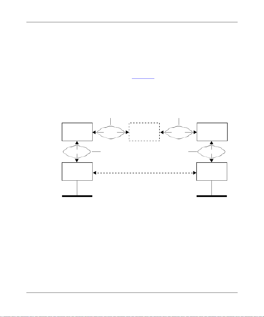
cut-through or zero-hop routing . Figur e 1-1
can communicate efficiently over an independent layer 2 (ATM) virtual channel,
established by means of MPOA and NHRP negotiations.
shows ho w users on LAN 1 or LAN 2
MPOA server 1
(MPS)
MPOA
MPOA client 1
(MPC)
ATM ELAN, PVC
or RFC 1577 SVC
NHRP NHRP
ATM ELAN
Cut-through (zero-hop) route (ATM SVC)
Established through MPOA/NHRP negotiations
MPOA servers
(MPSs)
ATM ELAN, PVC
or RFC 1577 SVC
ATM ELAN
MPOA server
(MPS)
MPOA
MPOA client 2
(MPC)
LAN 2LAN 1
BCC0029A
n
Figure 1-1. ATM Zero-Hop (Cut-Through) Routing
MPOA supports communication between an MPOA client (MPC), typically an
ATM edge device or switch, and its MPOA server (MPS), typically a router.
NHRP supports communication between MPSs.
1-2
305861-A Rev 00
Page 21

Understanding MPOA and NHRP
Although the connection between any two MPSs can be supported by an ATM
PVC, RFC 1577 SVC (ATM Classical IP), or emulated LAN (ATM LANE), the
connection between any MPC and its MPS must always be supported by an
ELAN, as shown in Figure 1-1 on page 1-2
.
Cut-through routing i s based o n the f act t hat, in most cases , data t ransfe r occur s at
a steady rate of flow. For example, data or file transfer from one legacy Ethernet
LAN to a remote counterpart usually involves multiple frames. A file transfer of
approximately 45 KB requires about 30 Ether net frames, all address ed to the same
destination.
In an MPOA environment, it is possible to:
• Identify, from the address field in the first frame of a data/file transfer, the
recipient of that data or file.
• Establish an SVC to the recipient.
The software then disassembles all 30 or so frames into approximately 900 ATM
cells and transmitts th em to the recipient by way of the virtual channel provided
by the SVC.
Network performa nce i mp roves as the cells follow a predetermined direct path, in
contrast to the hop-by-hop routing of the Ethernet frames. Network performance
improves markedly in the case of steady-stream deterministic data flows, such as
video.
MPOA Logical Components
MPOA operati ons are based on l ogical compone nts, which can be im plemented in
various configurations of hardware and software. MPOA logical components
include the following:
•MPOA clients
An MPOA client (MPC) resides in each ATM edge device (for example, an
ATM switch) served by an MPOA router. BayRS does not provide MPC
functionality. The primary function of the MPC is t o act, in ATM termi nology,
as an ingress or egress point for traffic establishing and subsequently using
network cut-throughs.
305861-A Rev 00
1-3
Page 22

Configuring MPOA and NHRP Services
The MPC moni tors traffic flows between a local source an d remote
destinations. Wh en traffic volume between a sour ce and a d estin ation exceeds
a preconfigured threshold level (for example x packets to the same network
layer address in y seconds), the MPC attempts to set up an SVC between the
source and destination workstations.
In attempting to set up an SVC, the MPC first looks in a local cache of
network layer-to-ATM address mappings. If the MPC finds the destination
address in its local cac he, it immediately be gins to est ablish the SVC. If it f ails
to locate the destination address in the local cache, it generates an MPOA
address resolution request to an adjacent MPOA server.
• MPOA routers
Each MPOA router that serves MPCs, directly or indirectly, includes a
collection of logical functions that map network layer addresses to ATM
addresses. Each MPO A router maintai ns tables of adjacent network layer (IP),
MAC laye r, and ATM addresses, in addition to s tandar d ro uting tabl es der ived
from a routing protocol (generally OSPF or RIP).
MPOA routers communicate over NHRP to map network layer addresses to
ATM addresses. BayRS provides MPOA router functionality to map IP
addresses to their ATM counterparts.
• MPOA servers
The MPOA server (MPS) is a logical function that mediates between local
MPCs and the MPOA router. It receives MPOA address resolution requests
from MPCs and passes them to the MPOA routing function. The MPOA
router, using NHRP, resolves the address and passes the requested ATM
address back to the MPS. The MPS, in turn, forwards the resolved address to
the requesting MPC. BayR S provides MPOA server func tionality.
MPOA Basic Elements
MPOA services provided by each Bay Networks router depend on the existence
of:
• An ATM emulated LAN (using LANE) between each MPC and its MPS.
• An ATM emulated LAN, ATM Classical IP (RFC 1577 SVC), or an ATM
PVC between any two MPSs. (See Figure 1-1 on page 1-2
• NHRP to resolve ATM and IP source and destination addresses.
• IP to route NHRP packets and other traffic between MPSs.
1-4
.)
305861-A Rev 00
Page 23

Understanding MPOA and NHRP
For more information about Go to
IP
LANE
NHRP “NHRP” on page 1-7
Establishing a Network Cut-Through
MPOA componen ts and elements fu nction together to establish an SVC bet ween a
source host and a destination host, as follows:
1.
A local MPC monitors traf f ic f lo w and mainta ins a count of pack ets addre ssed
over a specific interval to remote hosts. When the count exceeds a threshold
value, the MPC attempts to establish an SVC to the host.
To establish the virtual connection, the MPC needs the ATM address of the
host.
2.
The MPC first checks a local address resolution cache to map the known
network layer address with an ATM equivalent.
3.
If the cache search fails, the MPC issues an MPOA resolution request to the
local MPS function resident on the adjacent router.
4.
The local MPS hands the resolution request to the MPOA router component.
5.
The MPOA rou ter gener ates an NHRP address resolut ion reque st for t he ATM
address of the destination host. Standard routing protocols move the NHRP
request through the ne twork toward the destination host. Eventually, the
NHRP request reaches the egress router, that is, the router that serves the
target host.
Configuring IP Services
Configuring ATM Services
305861-A Rev 00
6.
The egress router forwards the request to its MPS entity.
7.
The remote MPS provides the ATM address of the destination host to its
NHRP entity.
If the destination host is connected to a legacy LAN, the MPS provides the
ATM address of the router that conn ect s to the legacy LAN. If th e dest ination
host is ATM-attached, the MPS provides the ATM address of the destination
host.
1-5
Page 24
Configuring MPOA and NHRP Services
8.
The remote MPOA router generates an NHRP address resolution reply
containing the ATM address pr ovi ded b y the MPS. Stan dard ro uting prot ocols
move the NHRP reply through the network to the local MPOA router.
9.
The local MPOA rout er sends the resolved address to the MPS, which then
caches and sends t he r esolved addre ss to the MPC that initiated the reso lut io n
process.
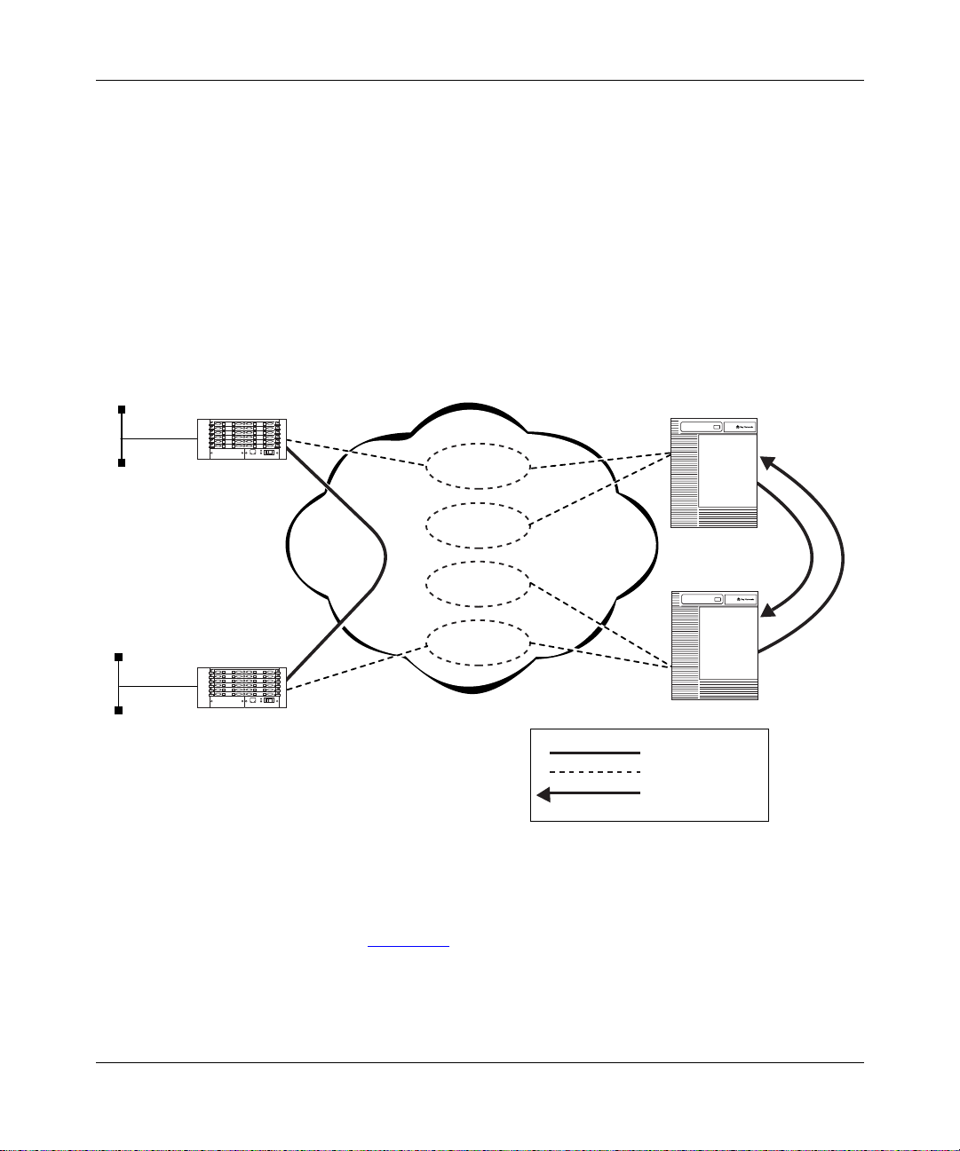
10.
The local MPC caches the address resolution information and establishes an
SVC to the remote MPC, establish ing the netw or k cut-thr ough connection f or
more efficient communication.
ATM MPC
10BASE-T
ATM network
ATM MPS
ELAN 1
ELAN 2
ATM MPC
10BASE-T
Figure 1-2. MPO A with Cut-Through VC
Note again t hat in Figure 1-2, the logical connection between any two MPSs can
be an ATM PVC or RFC 1577 SVC (ATM Classical IP) instead of an ELAN,
depending on your network topology requirements.
1-6
ELAN 3
ELAN 4
ATM MPS
Key
Cut-through VC
Logical connection
NHRP control VC
ATM0055A
305861-A Rev 00
Page 25

NHRP
Understanding MPOA and NHRP
NHRP is an address resolution protocol described in Internet RFC 2332.
As defined by the RFC, NHRP provides address resolution services by mapping
“internetworking layer addresses to NBMA subnetwork addresses.” As
implemented by Bay Networks, NHRP resolves IP to ATM addresses.
The IETF draft specifies behavior for NHRP clients and NHRP servers.
• The NHRP client (NHC) generates NHRP address resolution requests on
behalf of applications such as a local MPS.
• The NHRP server (NHS) responds to NHRP address resolution requests by
generating NHRP address resolution replies. For this purpose, the NHS
maintains a next-hop cache.
NHRP supports address resolution using seven formatted message types.
• NHRP resolution request
An NHRP resolution request is generated by an NHC and routed through the
ATM topology. Functionally eq uivalent to a stan dard ARP request, it contai ns
the layer 3 and layer 2 address of the originator, the layer 3 address of the
target destination, and a blank field reserved for the layer 2 address of the
target. As implemented by Bay Networks, the NHRP resolution request
contains the IP and ATM addresses of the originator and the IP address of the
target.
305861-A Rev 00
• NHRP resolution reply
An NHRP resolution reply is generated by an NHS in response to an NHRP
resolution request. Like an NHRP resolution request, it is routed through the
ATM topology. It is functionally e qui v alen t to a stan dard ARP response in th at
it replicates the information in the NHRP resolution request and supplies the
requested layer 2 (ATM) address.
• NHRP registration request
An NHRP registration request is generated by an NHC and directed toward
the local NHS. The NHRP registration request is used to register address
mapping data gathered by the NHC with the NHS. The NHS places mapping
data in its next-hop cache.
1-7
Page 26

Configuring MPOA and NHRP Services
• NHRP registration reply
An NHRP registration reply is generated by an NHS in response to an NHRP
registration request. It provides positive or negative acknowledgment of data
receipt.
• NHRP purge request
An NHRP purge request can be generated by either an NHC or an NHS. It
requests the recipi ent to delete pr evio usly cached informatio n that has become
invalid.
• NHRP purge reply
An NHRP purge reply is generated by either an NHC or an NHS in response
to an NHRP purge request. It provides positive acknowledgment of data
receipt.
• NHRP error indication
An NHRP error indication can be generated by either an NHC or an NHS. It
conveys error status to the sender of an NHRP message.
For More Information
1-8
For more information about MPOA and NHRP, refer to the following documents:
Heinanen, J. Multiprotocol Encapsulation over ATM Adaptation Layer 5.
RFC 1483. Network Working Group. July 1993.
Cole, B., N. Doraswamy, D. Katz, J. Luciani, D. Piscitello. NBMA Next Hop
Resolution Protocol (NHRP). RFC 2332. April 1998.
305861-A Rev 00
Page 27

Where to Go Next
Use the following table to determine where to go next.
If you want to Go to
Understanding MPOA and NHRP
Learn about ATM and PVCs.
Learn about LAN emulation.
Start MPOA and NHRP services. Chapter 2
Change defa ult settings for MPOA server parameters. Chapter 3
Change default settings for NHRP client or server
parameters.
Obtain information about Site Manager parameters. Appendix A
Obtain information about BCC parameters. Appendix B
Monitor ATM using the BCC show commands. Appendix C
Review an example MPOA/NHRP configuration
sequence.
Review the BCC configuration tree for MPOA and NHRP
services.
Configuring ATM Services
Chapter 4
Appendix D
Appendix E
305861-A Rev 00
1-9
Page 28

Page 29

Chapter 2
Starting MPOA and NHRP Services
This chapter describes how to create basic MPOA and NHRP configurations by
specifying v alues for r equired paramet ers only, and by accepting def ault v alues fo r
all other parameters.
This chapter contains the following information:
Topic Page
Starting Configuration Tools 2-1
Starting the MPOA Server 2-2
Starting NHRP on an ATM LEC, PVC, or Classical IP Service 2-5
Where to Go Next 2-16
Starting Configuration Tools
Before configuring MPOA or NHRP services, refer to the following user guides
for instructions on how to start and use the Bay Networks configuration tool of
your choice.
Configuration Tool User Guide
Bay Command Console (BCC)
Site Manager
305861-A Rev 00
Using the Bay Command Console (BCC)
Configuring and Managing Routers with
Site Manager
2-1
Page 30

Configuring MPOA and NHRP Services
Start ing the MPOA Server
To start the MPOA server, you must perform the following steps:
1.
Start ATM on the router. (See Configuring ATM Services.)
2.
Configure any ATM PVCs, SVCs (Classical IP), and LAN emulation client
(LEC) services that you need for MPOA/NHRP to operate within your
specific network topology. (See Chapter 1 and Configuring ATM Services.)
Be sure to:
• Specify LANE data encapsulation for each LEC that you require.
• Specify LLC-SNAP data encapsulation for each PVC that you require.
• Configure IP and NHRP on each LEC, PVC, and Classical IP (SVC)
service.
3.
Create an MPOA service record.
4.
Add an MPS to the MPOA service record.
5.
Ensure that a LECS has been configured on your network.
6.
Map any LEC services on the router to the desired local MPS.
Creating an MPOA Service Record
To run an MPOA server o v er ATM, you must f i rst cr eate an MPOA service record
on an ATM interface. Then you add one or more MPOA servers (MPSs) to the
MPOA service record.You can use the BCC or Site Manager to accomplish this
using default values for all parameters.
Using the BCC
To create an MPOA service record, navigate to the appropriate ATM interface
prompt and enter:
mpoa-service
2-2
305861-A Rev 00
Page 31

For example, on a System 5000™ router, the following command sequence:
• Creates an ATM interface on slot 5, module 3, connector 1.
• Creates an MPOA service on the ATM interface.
stack# atm slot 5 module 3 connector 1
atm/5/3/1# signaling
signaling/5/3/1# back
atm/5/3/1# mpoa-service
mpoa-service/5/3/1#
On a BLN®/BCN® router, the commands are identical, except that you do not
specify a module number for the ATM interface:
box# atm slot 5 connector 1
atm/5/1# signaling
signaling/5/1# back
atm/5/1# mpoa-service
mpoa-service/5/1#
Using Site Manager
To create an MPOA service using Site Manager, complete the following tasks:
Starting MPOA and NHRP Services
<-- (Signaling must be enabled for a new ATM interface.)
305861-A Rev 00
Site Manager Procedure
You do this System responds
1. In the Configuration Manager window,
click on an ATM link module interface (for
example,
2. Click on
3. Click on
4. Click on OK. The MPOA Service Record window
5. Go to the next section, “Adding an MPO A
Server,” or go to the next step to exit this
procedure.
6. Click on
).
ATM1
. The Edit ATM Connector window opens.
ATM
MPOA Server Attributes
. You return to the Edit ATM Connector
Done
. The MPOA Server Parameters window
The Select Connection Type window
opens.
opens.
opens.
window.
(continued)
2-3
Page 32

Configuring MPOA and NHRP Services
You do this System responds
7. Click on
8. Click on
Done
Done
By default, when you enter and then exit the MPOA Service Record window, you
automatically create and enable the MPOA service record using the default
settings. You need only enter and exit this window one time to create and enable
the MPOA service reco rd. However, for MPOA to operate, you must add at least
one MPS to the service record.
Note:
You can have only one MPOA service record per ATM interface.
However, this service record can contain up to four MPSs.
Adding an MPOA Server
You must add at least one MPS to any MPOA service that you create on an ATM
interface. Although not operational until fully configured, an MPS is enabled by
default when you add it to an MPOA service record.
Site Manager Procedure
. You return to the Select Connection Type
. You return to the Configuration Manager
(continued)
window.
window.
Using the BCC
2-4
A new MPS must be in the enabled state so that you can map it to one or more
LEC services. Then you can use either the BCC or Site Manager to map each
MPS to a specific LEC service on the router.
To add an MPS, navigate to the desired MPOA service prompt and enter:
mps mps-name
<mps-name>
For example, on a System 5000 router, the following command adds an MPS
named “east coast” to an MPOA service:
mpoa-service/5/3/1#
mps/eastcoast#
mps mps-name eastcoast
305861-A Rev 00
Page 33

Using Site Manager
To add an MPS to an MPOA service, complete the following tasks:
You do this System responds
Starting MPOA and NHRP Services
Site Manager Procedure
1. In the Configuration Manager window,
click on an ATM link module interface (for
example,
2. Click on
3. Click on
4. Click on
5. Click on
6. Click on OK. You return to the MPS List window. The
7. Repeat steps 5 and 6 to add additional
MPOA servers.
8. Go to the next section, “Starting NHRP on
an ATM LEC, PVC, or Classical IP
Service” or go to the next step to exit this
procedure.
9. Click on
10. Click on
11. Click on
12. Click on
).
ATM1
. The Edit ATM Connector window opens.
ATM
MPOA Server Attributes
. The MPS List window opens.
MPS
. The MPS Configuration Parameters
Add
. You return to the MPOA Service Record
Done
. You return to the Edit ATM Connector
Done
. You return to the Select Connection Type
Done
. You return to the Configuration Manager
Done
. The MPOA Server Parameters window
The Select Connection Type window
opens.
opens.
window opens.
MPS List window show s the add ed MPS.
window.
window.
window.
window.
Starting NHRP on an ATM LEC, PVC, or Classical IP Serv ice
Before configuring NHRP on a Bay Networks router, determine the type of link
between each pair of MPSs in your ATM network. After making this
determination, configure IP, RIP or OSPF, and NHRP on the LEC, PVC, or
Classical IP service (as determined for each MPS-to-MPS link).
305861-A Rev 00
2-5
Page 34

Configuring MPOA and NHRP Services
Note:
Enabling RIP or OSPF on an LEC, PVC, or Classical IP (SVC) service
is unnecessary if your network already has a routed path between MPSs.
Based on each type of link between two MPSs, proceed as follows:
MPS Link Service Go to
Emulated LAN (ELAN) LEC service Starting NHRP on an ATM LEC Service
Permanent virtual circuit
(PVC)
Switched virtual circuit
(SVC)
PVC service Starting NHRP on an ATM PVC
Classical IP se rvice Starting NHRP on an ATM Classical IP
Starting NHRP on an ATM LEC Service
To allow LANE and normally routed traffic to flow through an ATM LEC service
and between MPSs, enable IP and optiona lly a r outing protoco l (RIP or OSPF ) on
that IP interface.
Service
(RFC 1577 SVC) Service
Using the BCC
2-6
To allow NHRP address resolution requests and replies to flow through the same
ATM LEC service and between MPSs, you must enable NHRP on that service.
You can use either the BCC or Site Manager to add IP, RIP or OSPF, and NHRP
to an LEC service.
To add IP, RIP or OSPF, and NHRP to an existing LEC service:
1.
Navigate to the appropriate lec-service prompt and enter:
nhrp
2.
Navigate back to the lec-service prompt, and enter:
ip address
3.
At the resulting IP interface prompt, add the desired routing protocol
<IP_address>
mask
<subnet_mask>
(RIP or OSPF):
rip
305861-A Rev 00
Page 35

For example, on a System 5000 router, the following BCC commands navigate to
the lec-service named “newyork” and add NHRP, IP, and RIP to that service:
stack# atm/5/3/1
atm/5/3/1# lec-service/newyork
lec-service/newyork# nhrp
nhrp/newyork# back
ip/1.2.3.4/255.0.0.0# rip
rip/1.2.3.4#
When you add NHRP to any ATM LEC service, the BCC automatically creates
the global NHRP object at root level if you have not already done so.
Using Site Manager
To add NHRP to an existing LEC service, complete the following tasks:
You do this System responds
Starting MPOA and NHRP Services
Site Manager Procedure
1. In the Configuration Manager window,
click on the ATM interface (
which you want to add NHRP.
2. Click on
3. Click on
4. Click on the ATM LANE service record to
which you want to add NHRP.
5. Click on the Protocols menu in the upper
left hand corner of the window.
6. Choose
7. Select IP,
8. Click on OK. The IP Configuration window opens.
9. Set the following parameters:
• IP Address
• Subnet Mask
• Transmit Bcast Address
Click on
RIP, and OSPF Services
descriptions.
. The Edit ATM Connector window opens.
ATM
Service Attributes
Add/Delete
RIP
Help
. The Select Protocols window opens.
, and
or see
.
NHRP
Configuring IP, ARP,
for parameter
) on
ATM1
. The ATM Service Records List window
The Select Connection Type window
opens.
opens.
(continued)
305861-A Rev 00
2-7
Page 36

Configuring MPOA and NHRP Services
Site Manager Procedure
You do this System responds
10. Click on OK. The NHRP Network Configuration
11. Set the following parameters, or use
default values:
• NHRP Request Path
• Client Enable
• Client Reg Interval
• Client Hold Time
• Client Request Timeout
• Client Request Retry
• Client Max Pending Request Entries
• Server Enable
• Server Forward Enable
• Server Max Next Hop Entries
• Server Max Pending Request
Entries
Click on
descriptions beginning on page A-14.
12. Click on
13. Click on
14. Click on
15. Click on
or see the parameter
Help
OK.
. You return to the Edit ATM Connector
Done
. You return to the Select Connection Type
Done
. You return to the Configuration Manager
Done
(View Only)
(continued)
window opens.
You return to the ATM Service Records
List windo w which displays a summary of
the NHRP record that you configured.
window.
window.
window.
2-8
Mapping an MPS to a LAN Emulation Client
You must map an MPS to any LEC service likely to send and receive MPOA
resolution requests and replies over the ATM network. You can map one MPS to
one or more LEC services configured on the same ATM slot and connector.
305861-A Rev 00
Page 37

Using the BCC
Starting MPOA and NHRP Services
To map an MPS to an LEC service, navigate to that LEC service and enter:
mpoa-server mps-name
<mps-name>
For example, on a System 5000 router, the following BCC commands navigate to
the LEC service “newyork” and map the MPS named “eastcoast” to it:
stack#
atm/5/3/1#
lec-service/newyork#
mpoa-server/newyork#
atm/5/3/1
lec-service/newyork
mpoa-server mps-name eastcoast
Figure 2-1 shows the configuration hierarchy and logical mapping between the
MPS and the LE C in this example.
stack
atm/5/31/1
signaling/5/3/1
(mapping object)
lec-service/newyork
mpoa-server/newyork
mps-to-lec-service
mapping
305861-A Rev 00
mpoa-service/5/3/1 mps/eastcoast
BCC0031A
Figure 2-1. Mapping an MPS to an LEC Service
2-9
Page 38

Configuring MPOA and NHRP Services
Using Site Manager
To map an MPOA server (MPS) to a LEC service, complete the following tasks:
You do this System responds
Site Manager Procedure
1. In the Configuration Manager window,
click on an ATM link module interface (for
example,
2. Click on
3. Click on
4. Click on
5. Click on
6. Click on any LEC that you want to map to
the MPS.
7. Click on
8. Repeat steps 8 and 9 to map any
additional LECs.
9. Click on
10. Click on
11. Click on
12. Click on
13. Click on
).
ATM1
. The Edit ATM Connector window opens.
ATM
MPOA Server Attributes
. The MPS List window opens.
MPS
Mapping
Mapping
Done
Done
Done
Done
Done
. The LEC (to) MPS Mapping List window
. Site Manager maps the LEC to the MPS.
. You return to the MPS List window.
. You return to the MPOA Service Record
. You return to the Edit ATM Connector
. You return to the Select Connection Type
. You return to the Configuration Manager
. The MPOA Service Record window
The Select Connection Type window
opens.
opens.
opens.
window.
window.
window.
window.
2-10
305861-A Rev 00
Page 39

Starting NHRP on an ATM PVC Service
To allow normally routed traffic to flow through an ATM PVC service and
between MPSs, enable IP plus an opt ional routi ng proto col (RIP or OSPF) on tha t
IP interface. (Configure RIP or OSPF if no routed paths exist between MPSs in
your ATM network).
To allow NHRP address resolution requests and replies to flow through the same
ATM PVC service and between MPSs, you must enable NHRP on that service.
You can use either the BCC or Site Manager to add IP, RIP or OSPF, and NHRP
to an ATM PVC service.
Using the BCC
To add IP, RIP or OSPF, and NHRP to an existing ATM PVC service:
1.
Navigate to the appropriate pvc-service prompt and enter:
nhrp
2.
Navigate back to the pvc-service prompt, an d enter:
Starting MPOA and NHRP Services
305861-A Rev 00
ip address
3.
At the resulting IP interface prompt, add a routing protocol (RIP or
<IP_address>
mask
<subnet_mask>
OSPF):
rip
For example, on a System 5000 router, the following BCC commands navigate to
the pvc-service named “phoenix” and add NHRP, IP, and RIP:
stack#
atm/5/3/1#
pvc-service/phoenix#
nhrp/phoenix#
ip/1.2.3.6/255.0.0.0#
rip/1.2.3.6#
atm/5/3/1
pvc-service servicename phoenix
nhrp
back
rip
When you add NHRP to any ATM PVC service, the BCC automatically creates
the global NHRP object at root level if you have not already done so.
2-11
Page 40

Configuring MPOA and NHRP Services
Using Site Manager
To add NHRP to an exis ting ATM i nterface, complete the following tasks:
You do this System responds
Site Manager Procedure
1. In the Configuration Manager window,
click on the ATM interface (
which you want to add NHRP.
2. Click on
3. Click on
4. Click on the PVC service record to which
you want to add NHRP.
5. Click on the Protocols menu in the upper
left corner of the window.
6. Choose
7. Select IP,
8. Click on OK. The IP Configuration window opens.
9. Set the following parameters:
• IP Address
• Subnet Mask
• Transmit Bcast Address
Click on
RIP, and OSPF Services
descriptions.
10. Click on OK. The NHRP Network Configuration (NHRP
. The Edit ATM Connector window opens.
ATM
Service Attributes
Add/Delete
RIP
Help
. The Select Protocols window opens.
, and
or see
.
NHRP
Configuring IP, ARP,
for parameter
) on
ATM1
. The ATM Service Records List window
The Select Connection Type window
opens.
opens.
global parameters) window opens if
NHRP has not been configured on any
interface.
(continued)
2-12
305861-A Rev 00
Page 41

Starting MPOA and NHRP Services
Site Manager Procedure
You do this System responds
11.Use default values for the following
parameters:
• NHRP Request Path
• Client Enable
• Client Reg Interval
• Client Hold Time
• Client Request Timeout
• Client Request Retry
• Client Max Pending Request Entries
• Server Enable
• Server Forward Enable
• Server Max Next Hop Entries
• Server Max Pending Request
Entries
Click on
descriptions beginning on page A-14.
12. Click on
13. Click on
14. Click on
15. Click on
or see the parameter
Help
OK.
. You return to the Edit ATM Connector
Done
. You return to the Select Connection Type
Done
. You return to the Configuration Manager
Done
(continued)
You return to the ATM Service Records
List windo w which displays a summary of
the NHRP record that you configured.
window.
window.
window.
305861-A Rev 00
2-13
Page 42

Configuring MPOA and NHRP Services
Starting NHRP on an ATM Classical IP (RFC 1577 SVC) Service
To allow normally routed traffic to flow through an ATM SVC (Classical IP)
service and betw een MPSs, enable IP plus an optional routing p rot oc ol on that IP
interface. (Configure RIP or OSPF if no routed path exists betwee n MPS s in yo ur
ATM network).
To allow NHRP address resolution requests and replies to flow through the same
ATM Classical IP (SVC) service and between MPSs, you must enable NHRP on
that service.
You can use either the BCC or Site Manager to add IP, RIP or OSPF, and NHRP
to the appropriate ATM Classical IP (SVC) service.
When configuring an RFC 1577 SVC connection between a pair of MPSs, keep
the following in mind:
• The SVCs must use LLC/SNAP encapsulation (you cannot use NLPID or
NULL enca psulation on the SVC).
• You must configure the SVC with IP and NHRP.
• To avoid manually conf iguri ng adjac ent hos ts for eac h MPS, you may want t o
configure the SVC to run RIP.
Using the BCC
2-14
• Set the client mode for the SVC to client on one MPS and server on the other
MPS.
For instructions on configuring an SVC service record with LLC/SNAP
encapsulation, see Configuring ATM Services.
To add IP, RIP or OSPF, and NHRP to an existing ATM Classical IP (RFC 1577
SVC) service:
1.
Navigate to the desired classical-ip-service prompt and enter:
nhrp
2.
Navigate back to the classical-ip-service prompt, and enter:
ip address
<IP_address>
mask
<subnet_mask>
305861-A Rev 00
Page 43

Starting MPOA and NHRP Services
3.
At the resulting IP interface prompt, add the desired routing protocol
(RIP or OSPF):
rip
For example, on a System 5000 router, the following BCC commands navigate to
the classical-ip-service named “baltimore” and add IP, RIP, and NHRP to that
service:
stack#
atm/5/3/1#
classical-ip-service/baltimore#
nhrp/baltimore#
ip/1.2.3.6/255.0.0.0#
rip/1.2.3.6#
When you add NHRP to any ATM Classical IP service, the BCC automatically
creates the global NHRP object at root level if you have not already done so.
Using Site Manager
After you create an ATM SVC service record, the Add Protocols window opens.
T o add IP, NHRP, and RIP to an SVC service record, complete the follo wing tasks :
You do this System responds
1. Click on IP. A check mark appears in the IP box.
2. Click on
3. Click on
4. Click on OK. The IP Configuration window opens.
5. Set the following parameters:
atm/5/3/1
classical-ip-service servicename baltimore
back
rip
. A check mark appears in the RIP box
RIP
. A check mark appears in the NHRP box.
NHRP
• IP Address
• Subnet Mask
• Transmit Bcast Address
Click on
RIP, and OSPF Services
descriptions.
Help
Configuring IP, ARP,
or see
for parameter
nhrp
Site Manager Procedure
305861-A Rev 00
6. Click on OK. The ATM ARP Configuration window
opens.
(continued)
2-15
Page 44

Configuring MPOA and NHRP Services
You do this System responds
7. Set the following parameters:
• ATM ARP Mode
• ARP Server ATM Address Network
Prefix
• ARP Server ATM Address User Part
Click on
descriptions in
8. Click on OK. The NHRP Network Configuration
9. Click on OK. You return to the ATM Service Records
10. Click on
11. Click on
12. Click on
Where to Go Next
Site Manager Procedure
Help
or see the parameter
Configuring ATM Services
. You return to the Edit ATM Connector
Done
. You return to the Select Connection Type
Done
. You return to the Configuration Manager
Done
(continued)
.
window opens.
List window.
window.
window.
window.
2-16
Use the following table to determine where to go next.
If you want to Go to
Obtain an overview of MPOA and NHRP operation. Chapter 1
Change defa ult settings for MPOA server
parameters.
Change default settings for NHRP client or server
parameters.
Obtain information about Site Manager parameters. Appendix A
Obtain information about BCC parameters Appendix B
Monitor ATM using the BCC show commands. Appendix C
Review an example MPOA and NHRP configuration
process.
Review the BCC configuration tree for MPOA and
NHRP services.
Chapter 3
Chapter 4
Appendix D
Appendix E
305861-A Rev 00
Page 45

Chapter 3
Customizing MPOA Services
Bay Networks supports Multi-Protocol over ATM (MPOA) server configuration.
MPOA is the ATM Forum standard that specifies a way to efficiently transport
intersubnet, unicast data in a LANE environment. For general information about
the Bay Networks implementation of MPOA, see “Multi-Protocol over ATM” on
page 1-2.
This chapter describes how to customize an MPOA server configuration and
includes the following information:
305861-A Rev 00
Topic Page
Disabling and Reenabling an MPOA Service 3-2
Setting the MPS Address Generating Mode 3-3
Specifying an MPS Control ATM Address 3-5
Disabling and Reenabling MPOA Servers 3-8
Specifying the MPS Configuration Mode 3-10
Specifying a LECS ATM Address 3-11
Configuring a Unique Selector Byte for an MPS Address 3-14
Defining MPS Timer Values 3-16
Defining MPS Cache Values 3-25
Deleting MPOA Servers 3-28
Deleting an MPOA Service Record 3-29
Where to Go Next 3-31
You must create an MPOA service record before you can customize an MPS. For
information about creating an MPOA service record and starting the MPOA
server, see “Starting the MPOA Server” on page 2-2.
3-1
Page 46

Configuring MPOA and NHRP Services
Disabling and Reenabling an MPOA Service
The MPOA service on an ATM interface is normally enabled, which allows
MPOA serv ers (MPSs) conf igured on that serv ice to oper ate normally. If you need
to functionally disable all MPSs configured on a service simultaneously, disable
the underly ing MPOA service. You can do this using e ither the BCC or Site
Manager.
Using the BCC
To disable an MPOA Service, navigate to that service and enter:
state disabled
or:
To reenable an MPOA Service, navigate to that service and enter:
state enabled
For example, on a System 5000 router, the following commands:
3-2
• Navigate from root (
stack#) level to the MPOA service on existing interface
atm/5/3/1. (Assume that ATM signalling was enabled earlier with atm/5/3/1.)
• Disable the MPOA service, functionally disabling all MPSs configured on
atm/5/3/1.
• Reenable the same MPOA service, functionally reenabling all MPSs
configured on atm/5/3/1.
stack# atm slot 5 module 3 connector 1
atm/5/3/1# mpoa-service
mpoa-service/5/3/1# state disabled
mpoa-service/5/3/1# state enabled
mpoa-service/5/3/1#
305861-A Rev 00
Page 47

Using Site Manager
To disable or reenable the MPOA service record, complete the following tasks:
You do this System responds
Customizing MPOA Serv ic es
Site Manager Procedure
1. In the Configuration Manager window,
click on the ATM interface (
want to modify.
2. Click on
3. Click on
4. Set the
on
Help
on page A-3.
5. Click on
6. Click on
7. Click on
. The Edit ATM Connector window opens.
ATM
MPOA Server Attributes
Enable/Disable
or see the parameter description
. You return to the Edit ATM Connector
Done
. You return to the Select Connection Type
Done
. You return to the Configuration Manager
Done
parameter. Click
) that you
ATM1
. The MPOA Service Record window
The Select Connection Type window
opens.
opens.
window.
window.
window.
Setting the MPS Address Gen erating Mode
By default, a newly created MPS automatically uses the 13-byte ATM address
domain that it receives from the network switch. In this default mode (automatic
address generation), the MPS also uses the MAC address of the underlying ATM
interface as the basis for the 7-byte user suffix of the MPS address.
305861-A Rev 00
You can alternativ ely conf igur e a new MPS with an ATM address that you provide
in the MPOA service re cord. Whether derived automatic ally by MPOA or
manually from the MPO A ser vice re cord, th e addres s assign ed to each MPS is i ts
control ATM address.
You can use the BCC or Site Manager to change the MPS address generation
mode from automatic to manual.
3-3
Page 48

Configuring MPOA and NHRP Services
Using the BCC
To set the MPS address generating mode, navigate to the appropriate ATM
mpoa-service and enter the following command:
autogenerate { enabled
With this mode enabled, the MPS automatically generates an ATM address based
on information it receives from an LECS. If you disable this mode, the MPS uses
an ATM address based on the value you configured for the network-prefix and
user-suffix parameters of the MPOA service record. (If you disable address
autogeneration, be sure to configure values for network-prefix and user-suffix.)
For example, on a System 5000 router, the following commands:
• Navigate to the mpoa-service on ATM interface atm/5/3/1 on a System 5000
• Disable ATM address autogenerati on.
stack#
atm/5/3/1#
mpoa-service/5/3/1#
Using Site Manager
To set the MPS address generating mode, complete the following tasks:
You do this System responds
router.
atm/5/3/1
| disabled }
mpoa-service/5/3/1
autogenerate disabled
Site Manager Procedure
3-4
1. In the Configuration Manager window,
click on the ATM interface (
want to modify.
2. Click on
3. Click on
4. Set the
parameter. Click on
parameter description on page A-3.
. The Edit ATM Connector window opens.
ATM
MPOA Server Attributes
MPS Address Generate Mode
Help
) that you
ATM1
. The MPOA Service Record window
or see the
The Select Connection Type window
opens.
opens.
(continued)
305861-A Rev 00
Page 49

Customizing MPOA Serv ic es
Site Manager Procedure
You do this System responds
5. Click on
6. Click on
7. Click on
. You return to the Edit ATM Connector
Done
. You return to the Select Connection Type
Done
. You return to the Configuration Manager
Done
(continued)
window.
window.
window.
Note:
The MPS Address Generate Mode parameter also appears in the MPS
List window and the MPS Configuration Parameters window for display
purposes only. You must configure this parameter at the Site Manager MPOA
service record level.
Specifying an MPS Control ATM Address
By default, an MPS automatically inherits its:
• ATM address domain (network prefix) from the network switch
• ATM end-station identifier (6 bytes of the user suffix) from the MAC address
• ATM selector byte value (the least-significant or last byte of the user suffix)
Howe ver , if you configu re the MPO A service to ignore this in formation, you must
manually specify the ATM network prefix and user suffix that you want MPS to
use in its ATM address. These two elements together define the full MPS control
ATM address.
Network Prefix
The control ATM address network prefix specifies the ATM domain of the MPS.
This 13-byte portion of the ATM address can have values ranging from
XX000000000000000000000000 to XXFFFFFFFFFFFFFFFFFFFFFFFF.
305861-A Rev 00
of the underlying ATM interface
from the highest sele ctor b yt e v al ue cur rentl y conf i gured, inc remented by 1 to
ensure uniqueness.
3-5
Page 50

Configuring MPOA and NHRP Services
For user -conf ig ured netw ork pre fi x v alues, the XX b yte must contain 39 , 45, or 47.
These values define the authority and format identifier (AFI). The AFI byte
identifies the group responsible for allocating the prefix and the format the prefix
uses. For more information about the AFI byte, refer to the ATM Forum UNI
specification.
Entering an ATM address network prefix is opt ional . If you do not e nter a ne twork
prefix in the specified ra nge, the MPS accepts the first prefix val ue that it receives
from the loca l switch.
Note:
Each MPS obtains its ATM network prefix from the network prefix
assigned to the MPOA service record. This means that all MPSs that you add
to an MPOA service record will have the same ATM network prefix.
User Suffix
The control ATM address user part consi sts of a 6-b yte end-st ation ide ntif ier and a
1-byte selector field. This 7-byte portion of the ATM address can have values
ranging from 00000000000000 to FEFFFFFFFFFFFF.
Using the BCC
3-6
With ATM address generation in manual mode (autogenerati on disabled ), you can
use the BCC or Site Manager to manually configure a network prefix and user
suffix for the control ATM address.
To configure a value for the network prefix in the MPS control ATM address:
1.
Navigate to the appropriate mpoa-service prompt and ensure that the
autogenerate parameter has a value of disabled, for example:
mpoa-service/5/3/1#
autogenerate disabled
2.
Configure a value for the network-prefix portion of the MPS control
autogenerate
ATM address by entering:
network-prefix
3.
Configure a value for the user-suffix portion of the MPS control ATM
<13_byte_octet_string>
address by entering:
user-suffix
<7_byte_octet_string>
305861-A Rev 00
Page 51

For example, on a System 5000 router, the following commands:
• Navigate to the MPOA service on atm/5/3/1.
• Check to ensure that ATM address generation is in manual mode.
• Set a control ATM address network prefix and user suffix.
mpoa-service/5/3/1# autogenerate
autogenerate disabled
mpoa-service/5/3/1# network-prefix 39aabbccddeeffaabbccddeeff
mpoa-service/5/3/1# user-suffix abcdefabcdefab
mpoa-service/5/3/1#
Using Site Manager
This procedure assumes that the MPS Address Generate Mode parameter in the
MPOA Server Attributes window has been set to manual.
Now specify the control ATM address network pref ix b y completi ng the fol lo wing
tasks:
Customizing MPOA Serv ic es
Site Manager Procedure
305861-A Rev 00
You do this System responds
1. In the Configuration Manager window,
click on the ATM interface (
want to modify.
2. Click on
3. Click on
4. Set the
and
Ctrl A TM Addr User Part
Click on
descriptions on page A-4.
5. Click on
6. Click on
7. Click on
. The Edit ATM Connector window opens.
ATM
MPOA Server Attributes
Ctrl ATM Addr Network Prefix
or see the parameter
Help
. You return to the Edit ATM Connector
Done
. You return to the Select Connection Type
Done
. You return to the Configuration Manager
Done
) that you
ATM1
. The MPOA Service Record window
parameters.
The Select Connection Type window
opens.
opens.
window.
window.
window.
3-7
Page 52

Configuring MPOA and NHRP Services
Disabling and Reenabling MPOA Servers
When you finish mappin g an MPS to on e or more LECs on the same s lot, you can
use either the BCC or Site Manager to disable and subsequently reenable that
MPS for troubleshooting or other reasons.
Using the BCC
To disable a single MPS, navigate to the MPS you want to disable and enter:
state disabled
To reenable a disabled MPS, navigate to the MPS that you want to reenable and
enter:
state enabled
For example, on a System 5000 router, the following commands navigate to,
disable, and then reenable the MPS on mpoa-service/5/3/1:
Disabling:
stack# atm/5/3/1
atm/5/3/1# mpoa-service/5/3/1
mpoa-service/5/3/1# mps/newyork
mps/newyork# state disabled
3-8
Reenabling:
stack# atm/5/3/1
atm/5/3/1# mpoa-service/5/3/1
mpoa-service/5/3/1# mps/newyork
mps/newyork# state enabled
To disable or reenable multiple MPSs simultaneously, navigate to the MPOA
service on which the MPSs exist and enter:
disable mps/
<mpsname>
...
or:
enable mps/
<mpsname>
...
305861-A Rev 00
Page 53

For example , on a Syste m 5000 ro uter, the following BCC commands navi gate to
and disable two MPSs on mpoa-service/5/3/1:
stack# atm/5/3/1
atm/5/3/1# mpoa-service/5/3/1
mpoa-service/5/3/1# disable mps/newyork mps/chicago
mpoa-service/5/3/1#
Using Site Manager
To disable or reenable MPSs already mapped to LEC services, complete the
following tasks:
You do this System responds
Customizing MPOA Serv ic es
Site Manager Procedure
1. In the Configuration Manager window,
click on the ATM interface (
want to modify.
2. Click on
3. Click on
4. Click on
5. Click on the MPS that you want to modify.
6. Set the
on
Help
on page A-7.
7. Click on
8. Click on
9. Click on
10. Click on
. The Edit ATM Connector window opens.
ATM
MPOA Server Attributes
. The MPS List window opens.
MPS
Enable/Disable
or see the parameter description
. You return to the MPOA Service Record
Done
. You return to the Edit ATM Connector
Done
. You return to the Select Connection Type
Done
. You return to the Configuration Manager
Done
parameter. Click
) that you
ATM1
. The MPOA Service Record window
The Select Connection Type window
opens.
opens.
window.
window.
window.
window.
305861-A Rev 00
3-9
Page 54

Configuring MPOA and NHRP Services
Specifying the MPS Configuration Mode
The MPS configuration mode determines whether the MPS obtains configuration
parameter values (for example, timer settings) automatically from the LAN
emulation configuration server (LECS) or from the manual settings that you
provide. Once you determine the source from which the router must obtain MPS
configuration parameter values, set the MPS configuration mode to either
automatic or manual, accordingly.
In manual mode, you either acce pt the router’s MPS default timer values or
change those v al ues to sui t you r re qui rements (see “Defini ng MPS Timer Values
on page 3-16
You can specify the MPS configuration mode using either the BCC or Site
Manager.
Using the BCC
To specify the configuration mode used by each MPS, navigate to the appropriate
MPS and enter:
).
”
3-10
config-mode {automatic
manual
|
}
For example, on a System 5000 router, the following commands navigate to
mps/newyork on interface atm/5/3/1 and change the MPS configuration mode
from its default value (automatic) to its alternate value (manua l):
stack# atm/5/3/1
atm/5/3/1# mpoa-service/5/3/1
mpoa-service/5/3/1# mps/newyork
mps/newyork# config-mode manual
305861-A Rev 00
Page 55

Using Site Manager
To change the MPS configuration mode, complete the following tasks:
You do this System responds
Customizing MPOA Serv ic es
Site Manager Procedure
1. In the Configuration Manager window,
click on the ATM interface (
want to modify.
2. Click on
3. Click on
4. Click on
5. Click on the MPS that you want to modify.
6. Set the
Click on
description on page A-9.
7. Click on
8. Click on
9. Click on
10. Click on
. The Edit ATM Connector window opens.
ATM
MPOA Server Attributes
. The MPS List window opens.
MPS
MPS Config Mode
or see the parameter
Help
. You return to the MPOA Service Record
Done
. You return to the Edit ATM Connector
Done
. You return to the Select Connection Type
Done
. You return to the Configuration Manager
Done
) that you
ATM1
parameter.
Specifying a LECS ATM Address
The Select Connection Type window
opens.
. The MPOA Service Record window
opens.
window.
window.
window.
window.
305861-A Rev 00
You can use either the BCC or Site Manager to specif y which LECS you want the
MPS to use when obtaining parameter information. Entering this ATM address is
optional; if you do not enter an address, the MPS automatically uses the
well-known LECS ATM address to open a configuration VCC.
3-11
Page 56

Configuring MPOA and NHRP Services
To manually specify the LECS ATM address for an MPS, you must set the
following address elements:
• LECS ATM address network prefix
• LECS ATM address user suffix
These two elements together define the full ATM address o f the LECS.
Note:
The combined netw ork pr efix and user suffix mu st ma tch th e addre ss o f
the LECS fo r the network.
Network Prefix
The LECS ATM address network prefix specifies the ATM domain of the MPS.
This 13-byte portion of the ATM address can range from
XX000000000000000000000000 to XXFFFFFFFFFFFFFFFFFFFFFFFF.
The XX b yte typically cont ains 39, 45, or 47. These v alues def ine the autho rity and
format identifier (AFI). The AFI byte identifies the group responsible for
allocating the prefix and the format th at the prefix us es. For more information
about the AFI byte, refer to the ATM Forum UNI specification.
User Suffix
Using the BCC
3-12
The LEC ATM address user suffix typically contains a 6-byte end-station
identifier and a 1-byte selector field. This 7-byte portion of the ATM address can
range from 00000000000000 to FEFFFFFFFFFFFF.
Using the BCC, you can specify both parts of the address as the value for one
parameter (lecs-address).
To specify a LECS ATM address for the MPS, navigat e to the appro priate MPS
prompt and enter:
lecs-address
<20_byte_octet_string>
305861-A Rev 00
Page 57

For example, on a System 5000 router, the following BCC commands navigate to
mps/eastcoast and specify the 20-byte ATM address of the LECS that server
should use.
stack# atm/5/3/1
atm/5/3/1# mpoa-service/5/3/1
mpoa-service/5/3/1# mps/eastcoast
mps/eastcoast# lecs-address 45aabbccddeeff9988776655443311aabbccddff
mps/eastcoast#
Using Site Manager
Using Site Manager, you specify the network prefix and the user suffix as the
values for two separate parameters.
To specify a LECS ATM address, complete the following tasks:
You do this System responds
Customizing MPOA Serv ic es
Site Manager Procedure
1. In the Configuration Manager window,
click on the ATM interface (
want to modify.
2. Click on
3. Click on
4. Click on
5. Click on the MPS that you want to modify.
6. Set the
Click on
descriptions for the
Network Prefix
User Part
7. Click on
8. Click on
9. Click on
10. Click on
. The Edit ATM Connector window opens.
ATM
MPOA Server Attributes
. The MPS List window opens.
MPS
LECS ATM Address
or see the parameter
Help
LECS ATM Addr
and
LECS ATM Address
parameters on page A-6.
. You return to the MPOA Service Record
Done
. You return to the Edit ATM Connector
Done
. You return to the Select Connection Type
Done
. You return to the Configuration Manager
Done
) that you
ATM1
. The MPOA Service Record window
parameter.
The Select Connection Type window
opens.
opens.
window.
window.
window.
window.
305861-A Rev 00
3-13
Page 58

Configuring MPOA and NHRP Services
Note:
When you initially add a LECS ATM address, you do so by configuring
a separate ATM network prefix and ATM user part. However, when you
modify an existing LECS ATM address, you need only change one parameter
that contains both the ATM network prefix and the ATM user part suffix
portion of the LECS address.
Configuring a Unique Selector Byte for an MPS Address
If you disable ATM address autogeneration, a ne wly cre ated MPS uses the c ontrol
ATM address user suffix that you configured in the MPOA service record.
However, to ensure uniqueness among all ATM addresses used on the router, you
must additionally specify a unique value for the 1-byte selector field of the MPS
ATM address.
You can determine the user suffix values for MPSs currently configured on the
router by entering the following command at any BCC prompt:
show mpoa server
Based on the output of this command, assign to each new MPS a selector byte
value that is unique among selector byte values used for any other ATM addresses
configured on the router. For example, if the highest user suffix used by any
MPOA servers configured on the router is 0011223344556677 (selector byte
value = 77), you could assign the next available user suffix value,
0011223344556678 (selector byte value = 78).
You can set a unique selector byte value using either the BCC or Site Manager.
3-14
305861-A Rev 00
Page 59

Using the BCC
Customizing MPOA Serv ic es
To customize the selector byte of the control ATM address value inherited by the
MPS, navigate to the desired MPS and enter:
control-atm-address
For example, on a System 5000 router, the following commands:
• Navigate to the MPOA service on atm/5/3/1.
• Navigate to mps/newyork and reenter the full control ATM address (from the
stack#
atm/5/3/1#
mpoa-service/5/3/1#
mps/newyork#
mps/newyork#
Using Site Manager
This procedure assumes that the MPS Address Generate Mode parameter in the
MPOA Server Attributes window has been set to manual.
To specify the MPS control ATM address selector byte, complete the following
tasks:
<20_byte_octet_string>
MPOA servi ce le v el) as the v alue f or the MPS contr ol-atm- address pa ramete r ,
but with a unique value for the selector byte.
atm/5/3/1
mpoa-service/5/3/1
mps/newyork
control-atm-address 45112233445566778899AABBCC11223344556678
Site Manager Procedure
305861-A Rev 00
You do this System responds
1. In the Configuration Manager window,
click on the ATM interface (
want to modify.
2. Click on
3. Click on
4. Click on
5. Click on
. The Edit ATM Connector window opens.
ATM
MPOA Server Attributes
. The MPS List window opens.
MPS
. The MPS Configuration Parameters
Add
) that you
ATM1
. The MPOA Service Record window
The Select Connection Type window
opens.
opens.
window opens.
(continued)
3-15
Page 60

Configuring MPOA and NHRP Services
Site Manager Procedure
You do this System responds
6. Set the
Byte
parameter description on page A-7.
7. Click on
8. Click on
9. Click on
10. Click on
11. Click on
MPS Ctrl ATM Address Selector
parameter. Click on
. You return to the MPS List window.
Done
. You return to the MPOA Service Record
Done
. You return to the Edit ATM Connector
Done
. You return to the Select Connection Type
Done
. You return to the Configuration Manager
Done
Defining MPS Timer Values
Setting the MPS conf igurat ion mode to manu al allo ws you to c ustomize v alue s for
the following MPS timers:
• Keepalive time
Help
(continued)
or see the
window.
window.
window.
window.
3-16
• Keepalive lifetime
• Initial retry time
• Maximum retry time
•Give up time
• Default holding time
305861-A Rev 00
Page 61

Customizing MPOA Serv ic es
Setting the Transmission Interval for MPOA Keepalive Packets
The keepalive time specifies how often the MPS must transmit MPOA keepalive
packets. By default, the value is 10 seconds. However, you can set the keepalive
time to any value from 1 to 300 seconds using either the BCC or Site Manager.
Using the BCC
To set the keepalive time, navigate to the desired MPS and enter:
keep-alive-time
For example, on a System 5000 router, the following BCC commands navigate
from root level to mps/eastcoast and set the MPS keepalive time to 100 seconds:
stack#
atm/5/3/1#
mpoa-service/5/3/1#
mps/eastcoast#
mps/eastcoast#
Using Site Manager
To set the keepalive time, complete the following tasks:
You do this System responds
1. In the Configuration Manager window,
2. Click on
3. Click on
4. Click on
5. Click on the MPS that you want to modify.
6. Set the
7. Click on
<1-300
atm/5/3/1
mpoa-service/5/3/1
click on the ATM interface (
want to modify.
. The Edit ATM Connector window opens.
ATM
MPOA Server Attributes
. The MPS List window opens.
MPS
Keep Alive T ime
on
on page A-12.
or see the parameter description
Help
. You return to the MPOA Service Record
Done
>
mps/eastcoast
keep-alive-time 100
Site Manager Procedure
The Select Connection Type window
) that you
ATM1
. The MPOA Service Record window
parameter. Click
opens.
opens.
window.
(continued)
305861-A Rev 00
3-17
Page 62

Configuring MPOA and NHRP Services
Site Manager Procedure
You do this System responds
8. Click on
9. Click on
10. Click on
. You return to the Edit ATM Connector
Done
. You return to the Select Connection Type
Done
. You return to the Configuration Manager
Done
(continued)
window.
window.
window.
Setting the Valid Lifetime for Keepalive Packets
The keepali v e life time is t he le ngth of t ime that an MPOA client (MPC) considers
valid a k eepali v e packet se nt by its MPS. (The packe t contains it s keepa liv e v alue.)
By default, the keepalive lifetime is 35 seconds. However, you can set this value
from 3 to 1000 seconds using either the BCC or Site Manager.
Using the BCC
To set the keepalive lifetime, navigate to the desired MPS and enter:
keep-alive-lifetime
<3-1000
>
3-18
For example, on a System 5000 router, the following BCC commands navigate
from root level to mps/eastcoast and set the MPS keepalive lifetime to 500
seconds:
stack#
atm/5/3/1#
mpoa-service/5/3/1#
mps/eastcoast#
mps/eastcoast#
atm/5/3/1
mpoa-service/5/3/1
mps/eastcoast
keep-alive-lifetime 500
305861-A Rev 00
Page 63

Using Site Manager
To set the keepalive lifetime, complete the following tasks:
You do this System responds
Customizing MPOA Serv ic es
Site Manager Procedure
1. In the Configuration Manager window,
click on the ATM interface (
want to modify.
2. Click on
3. Click on
4. Click on
5. Click on the MPS that you want to modify.
6. Set the
Click on
description on page A-12.
7. Click on
8. Click on
9. Click on
10. Click on
. The Edit ATM Connector window opens.
ATM
MPOA Server Attributes
. The MPS List window opens.
MPS
Keep Alive Life Time
or see the parameter
Help
. You return to the MPOA Service Record
Done
. You return to the Edit ATM Connector
Done
. You return to the Select Connection Type
Done
. You return to the Configuration Manager
Done
Setting the Initial Retry Time
The Select Connection Type window
) that you
ATM1
. The MPOA Service Record window
parameter.
opens.
opens.
window.
window.
window.
window.
305861-A Rev 00
The initial ret ry ti me is used by the MPOA retry mechani sm. By def ault, t he value
is 5 seconds. However, you can set this value from 1 to 300 seconds using either
the BCC or Site Manager.
3-19
Page 64

Configuring MPOA and NHRP Services
Using the BCC
To set the initial retry time, navigate to the appropriate MPS and enter:
initial-retry-time
For example, on a System 5000 router, the following commands navigate from
root level to mps/eastcoast and set the MPS initial retry time to 50 seconds:
stack#
atm/5/3/1#
mpoa-service/5/3/1#
mps/eastcoast#
mps/eastcoast#
Using Site Manager
To set the initial r etry time, complete the following tasks:
You do this System responds
1. In the Configuration Manager window,
2. Click on
3. Click on
4. Click on
5. Click on the MPS that you want to modify.
6. Set the
7. Click on
8. Click on
9. Click on
10. Click on
<1-300
atm/5/3/1
mpoa-service/5/3/1
click on the ATM interface (
want to modify.
. The Edit ATM Connector window opens.
ATM
MPOA Server Attributes
. The MPS List window opens.
MPS
Initial Retry Time
Click on
description on page A-11.
or see the parameter
Help
. You return to the MPOA Service Record
Done
. You return to the Edit ATM Connector
Done
. You return to the Select Connection Type
Done
. You return to the Configuration Manager
Done
>
mps/eastcoast
initial-retry-time 50
Site Manager Procedure
The Select Connection Type window
) that you
ATM1
. The MPOA Service Record window
parameter.
opens.
opens.
window.
window.
window.
window.
3-20
305861-A Rev 00
Page 65

Setting the Maximum Retry Time
The maximum retry time is used by the MP OA retry mechanism. By default, the
value is 40 se conds. However, yo u can s et th is value from 10 to 300 seconds using
either the BCC or Site Manager.
Using the BCC
To set the maximum retry time, navigate to the desired MPS and enter:
Customizing MPOA Serv ic es
retry-time-maximum
For example, on a System 5000 router, the following commands navigate from
root level to mps/eastcoast and set the MPS maximum retry time to 200 seconds:
stack#
atm/5/3/1#
mpoa-service/5/3/1#
mps/eastcoast#
mps/eastcoast#
Using Site Manager
To set the maximum retry time, complete the following tasks:
You do this System responds
1. In the Configuration Manager window,
2. Click on
3. Click on
4. Click on
5. Click on the MPS that you want to modify.
6. Set the
7. Click on
<10-300
atm/5/3/1
mpoa-service/5/3/1
mps/eastcoast
retry-time-maximum 200
click on the ATM interface (
want to modify.
. The Edit ATM Connector window opens.
ATM
MPOA Server Attributes
. The MPS List window opens.
MPS
Maximum Retry Time
Click on
description on page A-13.
or see the parameter
Help
. You return to the MPOA Service Record
Done
>
Site Manager Procedure
The Select Connection Type window
) that you
ATM1
. The MPOA Service Record window
parameter.
opens.
opens.
window.
(continued)
305861-A Rev 00
3-21
Page 66

Configuring MPOA and NHRP Services
Site Manager Procedure
You do this System responds
8. Click on
9. Click on
10. Click on
. You return to the Edit ATM Connector
Done
. You return to the Select Connection Type
Done
. You return to the Configuration Manager
Done
(continued)
window.
window.
window.
Setting the Time to Wait for Responses to Resolution Requests
The give-up time is the minimum amount of time that the MPS must wait before
giving up on a pending resolution request. By default, the value is 40 seconds.
However, you can set this value from 5 to 300 seconds using either the BCC or
Site Manager.
Using the BCC
To set the give-up time, navigate to the desired MPS and enter:
give-up-time
<5-300
>
3-22
For example, on a System 5000 router, the following BCC commands navigate
from root level to mps/eastcoast and set the MPS give-up time to 175 seconds:
stack#
atm/5/3/1#
mpoa-service/5/3/1#
mps/eastcoast#
mps/eastcoast#
atm/5/3/1
mpoa-service/5/3/1
mps/eastcoast
give-up-time 175
305861-A Rev 00
Page 67

Using Site Manager
To set the give-up time, complete the following tasks:
You do this System responds
Customizing MPOA Serv ic es
Site Manager Procedure
1. In the Configuration Manager window,
click on the ATM interface (
want to modify.
2. Click on
3. Click on
4. Click on
5. Click on the MPS that you want to modify.
6. Set the
or see the parameter description on
Help
page A-10.
7. Click on
8. Click on
9. Click on
10. Click on
. The Edit ATM Connector window opens.
ATM
MPOA Server Attributes
. The MPS List window opens.
MPS
Give Up Time
. You return to the MPOA Service Record
Done
. You return to the Edit ATM Connector
Done
. You return to the Select Connection Type
Done
. You return to the Configuration Manager
Done
parameter. Click on
) that you
ATM1
. The MPOA Service Record window
The Select Connection Type window
opens.
opens.
window.
window.
window.
window.
Setting the Valid Interval for Replies to Resolution Requests
305861-A Rev 00
The default holding time determines how long the client considers resolution
replies held in the local cache as valid. By default, the value is 20 minutes.
However, you can set this value from 1 to 120 minutes using either the BCC or
Site Manager.
3-23
Page 68

Configuring MPOA and NHRP Services
Using the BCC
To set the default holding time, navigate to the desired MPS and enter:
default-holding-time
For example, on a System 5000 router, the following BCC commands navigate
from root level to mps/eastcoast and set the MPS default holding time to
90 minutes:
stack#
atm/5/3/1#
mpoa-service/5/3/1#
mps/eastcoast#
mps/eastcoast#
Using Site Manager
To set the default holding time, c omplete the following tasks:
You do this System responds
1. In the Configuration Manager window,
2. Click on
3. Click on
4. Click on
5. Click on the MPS that you want to modify.
6. Set the
7. Click on
8. Click on
9. Click on
10. Click on
<1-120
atm/5/3/1
mpoa-service/5/3/1
mps/eastcoast
default-holding-time 90
click on the ATM interface (
want to modify.
. The Edit ATM Connector window opens.
ATM
MPOA Server Attributes
. The MPS List window opens.
MPS
Default Holding Time
Click on
description on page A-10.
or see the parameter
Help
. You return to the MPOA Service Record
Done
. You return to the Edit ATM Connector
Done
. You return to the Select Connection Type
Done
. You return to the Configuration Manager
Done
>
Site Manager Procedure
The Select Connection Type window
) that you
ATM1
. The MPOA Service Record window
parameter.
opens.
opens.
window.
window.
window.
window.
3-24
305861-A Rev 00
Page 69

Defining MPS Cache Values
The MPS can contain cache information upon initialization and can accumulate
this information duri ng its opera tion. Bay Networks provides control over this
cache information.
Customizing MPOA Serv ic es
Caution:
The values you set for cache parameters affect router memory
resources. Use caution when setting higher values.
Setting the Initial Cache Size
The initial cache size specifies the maximum number of cache units that the MPS
can keep upon initialization. By default, the MPS can have a maximum initial
cache size of 100 units. ( Its act ual in itia l si ze is typ icall y zero.) You can use either
the BCC or Site Manager to set the maximum initial cache size to any value from
50 to 500 units.
Using the BCC
To set the initial cache size, navigate to the appropriate MPS and enter:
initial-cache-size
For example, on a System 5000 router, the following BCC commands navigate
from root level to mps/eastcoast and set the MPS initial cache size to 150 units:
stack# atm/5/3/1
atm/5/3/1# mpoa-service/5/3/1
mpoa-service/5/3/1# mps/eastcoast
mps/eastcoast# initial-cache-size 150
mps/eastcoast#
<50-500
>
305861-A Rev 00
3-25
Page 70

Configuring MPOA and NHRP Services
Using Site Manager
To set the initial cache size, complete the following tasks:
You do this System responds
Site Manager Procedure
1. In the Configuration Manager window,
click on the ATM interface (
want to modify.
2. Click on
3. Click on
4. Click on
5. Click on the MPS that you want to modify.
6. Set the
Click on
description on page A-11.
7. Click on
8. Click on
9. Click on
10. Click on
. The Edit ATM Connector window opens.
ATM
MPOA Server Attributes
. The MPS List window opens.
MPS
Initial Cache Size
or see the parameter
Help
. You return to the MPOA Service Record
Done
. You return to the Edit ATM Connector
Done
. You return to the Select Connection Type
Done
. You return to the Configuration Manager
Done
Setting the Maximum Cache Size
The Select Connection Type window
) that you
ATM1
. The MPOA Service Record window
parameter.
opens.
opens.
window.
window.
window.
window.
3-26
The maximum cache size specifies the maximum number of cache units that the
MPS can store at any time. B y default, the MPS can have a maxi mum cache size
of 500 units. However, you can use either the BCC or Site Manager to set the
maximum cache size to any value from 100 to 2000 units.
305861-A Rev 00
Page 71

Using the BCC
Customizing MPOA Serv ic es
To set the maximum cache size, navigate to the appropriate MPS and enter:
maximum-cache-size
For example, on a System 5000 router, the following BCC commands navigate
from root level to mps/eastcoast and set the MPS maximum cache size to 300
units:
stack#
atm/5/3/1#
mpoa-service/5/3/1#
mps/eastcoast#
mps/eastcoast#
Using Site Manager
To set the maximum cache size, complete the following tasks:
You do this System responds
1. In the Configuration Manager window,
2. Click on
3. Click on
4. Click on
5. Click on the MPS that you want to modify.
<100-2000
atm/5/3/1
mpoa-service/5/3/1
mps/eastcoast
maximum-cache-size 300
click on the ATM interface (
want to modify.
. The Edit ATM Connector window opens.
ATM
MPOA Server Attributes
. The MPS List window opens.
MPS
>
Site Manager Procedure
The Select Connection Type window
) that you
ATM1
. The MPOA Service Record window
opens.
opens.
305861-A Rev 00
6. Set the
Click on
description on page A-13.
7. Click on
8. Click on
Maximum Cac he Size
or see the parameter
Help
. You return to the MPOA Service Record
Done
. You return to the Edit ATM Connector
Done
parameter.
window.
window.
(continued)
3-27
Page 72

Configuring MPOA and NHRP Services
You do this System responds
9. Click on
10. Click on
. You return to the Select Connection Type
Done
. You return to the Configuration Manager
Done
Deleting MPOA Servers
You can use either the BCC or Si te Mana ger t o del et e one or mor e MPSs f rom an
MPOA service record.
Using the BCC
To delete a single MPS, navigate to the MPS that you want to delete and enter:
delete
For example, on a System 5000 router, the following commands navigate to and
delete the MPS on mpoa-service/5/3/1:
stack# atm/5/3/1
atm/5/3/1# mpoa-service/5/3/1
mpoa-service/5/3/1# mps/newyork
mps/newyork# delete
mpoa-service/5/3/1#
Site Manager Procedure
window.
window.
(continued)
3-28
If you want to delete multiple MPSs simultaneously, navigate to the MPOA
service on which the MPSs exist, and enter:
delete mps/
<mpsname>
...
For example, on a System 5000 router, the following commands navigate to and
delete two MPSs on mpoa-service/5/3/1:
stack# atm/5/3/1
atm/5/3/1# mpoa-service/5/3/1
mpoa-service/5/3/1# delete mps/newyork mps/chicago
mpoa-service/5/3/1#
305861-A Rev 00
Page 73

Using Site Manager
To delete an individual MPS, complete the following tasks:
You do this System responds
Customizing MPOA Serv ic es
Site Manager Procedure
1. In the Configuration Manager window,
click on the ATM interface (
want to modify.
2. Click on
3. Click on
4. Click on
5. Click on the MPS that you want to delete.
6. Click on
7. Click on
8. Click on
9. Click on
10. Click on
. The Edit ATM Connector window opens.
ATM
MPOA Server Attributes
. The MPS List window opens.
MPS
. Site Manager deletes the MPS.
Delete
. You return to the MPOA Service Record
Done
. You return to the Edit ATM Connector
Done
. You return to the Select Connection Type
Done
. You return to the Configuration Manager
Done
) that you
ATM1
. The MPOA Service Record window
Deleting an MPOA Service Record
You can delete MPOA services from an A TM interface completely using either the
BCC or Site Manager.
The Select Connection Type window
opens.
opens.
window.
window.
window.
window.
Using the BCC
305861-A Rev 00
Navigate to the MPOA service you want to delete and enter:
delete
3-29
Page 74

Configuring MPOA and NHRP Services
For example, on a System 5000 router, the following commands navigate to and
delete the MPOA service on interface atm/5/3/1:
stack# atm/5/3/1
atm/5/3/1# mpoa-service/5/3/1
mpoa-service/5/3/1# delete
atm/5/3/1#
Using Site Manager
To delete MPOA from the interface entirely, you must delete the MPOA service
record. To delete the MPOA service record, complete the following tasks:
You do this System responds
Site Manager Procedure
1. In the Configuration Manager window,
click on the ATM interface (
want to modify.
2. Click on
3. Click on
4. Click on
5. Click on
6. Click on
7. Click on
8. Click on
. The Edit ATM Connector window opens.
ATM
MPOA Server Attributes
. Site Manager asks whether you really
Delete
. Site Manager deletes the service record.
Yes
. You return to the Edit ATM Connector
Done
. You return to the Select Connection Type
Done
. You return to the Configuration Manager
Done
) that you
ATM1
. The MPOA Service Record window
The Select Connection Type window
opens.
opens.
want to delete MPOA from this interface.
window.
window.
window.
3-30
305861-A Rev 00
Page 75

Where to Go Next
Use the following table to determine where to go next.
If you want to Go to
Customizing MPOA Serv ic es
Learn about ATM concepts.
Learn about MPOA and NHRP concepts. Chapter 1
Change default settings for NHRP client or server
parameters.
Obtain information about Site Manager MPOA and
NHRP parameters.
Obtain information about BCC MPOA and NHRP
parameters.
Monitor MPOA and NHRP using the BCC show
commands.
Review a BCC MPOA/NHRP example configuration
sequence.
Review the BCC MPOA/NHRP configuration tree. Appendix E
Configuring ATM Services
Chapter 4
Appendix A
Appendix B
Appendix C
Appendix D
305861-A Rev 00
3-31
Page 76

Page 77

Chapter 4
Customizing NHRP Services
This chapter includes the following information:
Accessing NHRP Client and Server Global Parameters 4-2
Disabling NHRP on an LEC or PVC or Classical IP Service 4-4
Deleting NHRP from an LEC or PVC or SVC Service 4-6
Deleting NHRP Globall y 4-7
Where to Go Next 4-8
305861-A Rev 00
Note:
We recommend that you start and maintain NHRP with all default
settings on the router. However, if you need to customize NHRP parameter
values, you can use either the BCC or Site Manager to accomplish that task.
4-1
Page 78

Configuring MPOA and NHRP Services
The BCC and Site Manager allow you to edit values for the following NHRP
parameters:
BCC Parameter Equivalent Site Manager Parameter
client Client Enable
client-registration-interval Client Reg Interval
client-hold-time Client Hold Time
client-request-timeout Client Request Timeout
client-request-retry Client Request Retry
client-requests-maximum Client Max Pending Request Entries
server Server Enable
server-forwarding Server Forward Enable
server-next-hop-maximum Server Max Next Hop Entries
server-requests-maximum Server Max Pending Request Entries
next-hop-cache-size Max Next Hop Cache Size
The BCC and Site Manager also allow you to modify the configured state of
NHRP on a PVC or LEC service. (See ““
Classical IP Service” on page 4 - 4 .”)
Disabling NHRP on an LEC or PVC or
Accessing NHRP Client and Server Global Parameters
You can customize the configurable global parameters of NHRP, using either the
BCC or Site Manager.
Using the BCC
To access NHRP client and server parameters from root level (box# or stack#),
enter:
nhrp
Once you enter the NHRP context, enter the
parameters you can modify using the BCC and what are their current (default)
values.
4-2
info
command to see which
305861-A Rev 00
Page 79

Customizing NHRP Services
For example, the following BCC commands:
• Navigate to global NHRP.
• List NHRP client and server parameters that you can modify.
stack# nhrp
nhrp/atm/ip# info
client enabled
client-registration-interval 25
client-hold-time 30
client-request-timeout 10
client-request-retry 3
client-requests-maximum 100
server enabled
server-forwarding enabled
server-next-hop-maximum 5
server-requests-maximum 100
next-hop-cache-size 16
Read about these NHRP parameters in Appendix B. To modify any configurable
NHRP client or server parameter, enter:
<parameter_name> <value>
For example, to change the value for the client-registration-interval to 35 seconds,
and the server-next-hop-maximum to 6 ent ries, enter the following commands:
nhrp/atm/ip# client-registration-interval 35
nhrp/atm/ip# server-ne xt- hop-m axi mum 6
Using Site Manager
To edit an NHRP record, complete the following tasks:
You do this System responds
1. In the Configuration Manager window,
2. Choose IP. The IP menu opens.
3. Choose
4. Choose
305861-A Rev 00
click on
Site Manager Procedure
The Protocols menu opens.
Protocols
NHRP
NhrpNetTable
.
. The NHRP menu opens.
. The NHRP NetEntry List window opens.
(continued)
4-3
Page 80

Configuring MPOA and NHRP Services
Site Manager Procedure
You do this System responds
5. Click on the NHRP entry that you want to
edit.
6. Edit the following parameters as required:
• NHRP Request Path
• Client Enable
• Client Reg Interval
• Client Hold Time
• Client Request Timeout
• Client Request Retry
• Client Max Pending Request Entries
• Server Enable
• Server Forward Enable
• Server Max Next Hop Entries
• Server Max Pending Request
Entries
Click on
descriptions beginning on page A-14.
7. Click on
or see the parameter
Help
. You return to the Configuration Manager
Done
(continued)
Site Manager displays the current NHRP
entry-specific parameters .
window.
Disabling NHRP on an LEC or PVC or Classical IP Service
Using the BCC
4-4
You can use either the BCC or Site Ma nager to disable NHRP on an LEC, PVC, or
SVC (ATM Classical IP) service.
Note:
You cannot disable NHRP globally ( across all ATM slots) on the router .
You can disable NHRP only on an individual LEC, PVC, or Classical IP
(SVC) service.
To disable NHRP on an LEC, PVC, or SVC (ATM Classical IP) service, navigate
to NHRP on the appropriate service and enter:
disable
305861-A Rev 00
Page 81

For example, on a System 5000 router, the following BCC commands navigate to
the LEC service on atm/5/3/1 and disable NHRP on that service:
stack# atm/5/3/1
atm/5/3/1# lec-service/newyork
lec-service/newyork# nhrp
nhrp/newyork# disable
Using Site Manager
To disable an NHRP interface, complete the following tasks:
You do this System responds
Customizing NHRP Services
Site Manager Procedure
1. In the Configuration Manager window,
click on
2. Choose IP. The IP menu opens.
3. Choose
4. Choose
5. Click on the NHRP interface that yo u wa nt
to disable.
6. Set the
Click on
description on page A-14.
7. Click on
Protocols
NHRP
Interfaces
Enable
Help
Done
.
. The NHRP menu opens.
. The NHRP Interface List window opens.
parameter to
or see the parameter
. You return to the Configuration Manager
Disable
The Protocols menu opens.
.
window.
305861-A Rev 00
4-5
Page 82

Configuring MPOA and NHRP Services
Deleting NHRP from an LEC or PVC or SVC Serv ice
You can use either the BCC or Site Manager to delete NHRP from an LEC, PVC,
or SVC (ATM Classical IP) service.
Using the BCC
T o delete NHRP from an LEC, PVC, or SVC (ATM Classical IP) service, na vi gate
to the appropriate service and enter:
delete
For example, on a System 5000 router, the following BCC commands navigate to
the LEC service on atm/5/3/1 and delete NHRP from that service:
stack# atm/5/3/1
atm/5/3/1# lec-service/newyork
lec-service/newyork# nhrp
nhrp/newyork# delete
lec-service/newyork#
Using Site Manager
4-6
To delete an NHRP interface, complete the following tasks:
Site Manager Procedure
You do this System responds
1. In the Configuration Manager window,
click on
2. Choose IP. The IP menu opens.
3. Choose
4. Choose
5. Click on the NHRP interface that yo u wa nt
to delete.
6. Click on
7. Click on
Protocols
NHRP
Interfaces
Delete
Done
.
. The NHRP menu opens.
. The NHRP Interface List window opens.
. Site Manager deletes the NHRP interface
. You return to the Configuration Manager
The Protocols menu opens.
you selected.
window.
305861-A Rev 00
Page 83

Deleting NHRP Globally
You can use either the BCC or Site Manager to delete NHRP services globally
from the router.
Using the BCC
To delete NHRP using the BCC, you must first delete all NHRP interfaces
configured on LEC, PVC, or SVC (Classical IP) services, then delete the global
NHRP object.
For example, on a System 5000 router, the following commands:
• Delete NHRP from lec-service/newyork and from pvc-service/chicago.
• Delete global NHRP from all slots.
stack# atm/5/3/1
atm/5/3/1# lec-service/newyork
lec-service/newyork# nhrp
nhrp/newyork# delete
lec-service/newyork# pvc-service/chicago
pvc-service/chicago# nhrp
nhrp/chicago# delete
pvc-service/chicago# stack
stack# nhrp
nhrp/atm/ip# delete
stack#
Customizing NHRP Services
Using Site Manager
To globally delete NHRP, complete the following tasks:
You do this System responds
1. In the Configuration Manager window,
2. Choose IP. The IP menu opens.
3. Choose
305861-A Rev 00
click on
Site Manager Procedure
The Protocols menu opens.
Protocols
NHRP
.
. The NHRP menu opens.
(continued)
4-7
Page 84

Configuring MPOA and NHRP Services
You do this System responds
4. Choose
5. Click on
Where to Go Next
Use the following table to determine where to go next.
If you want to Go to
Obtain an overview of MPOA and NHRP operation. Chapter 1
Change default settings for MPOA server parameters. Chapter 3
Obtain information about Site Manager NHRP parameters. Appendix A
Obtain information about BCC NHRP parameters. Appendix B
Monitor ATM using the BCC show commands. Appendix C
Review a BCC MPOA/NHRP example configuration sequence. Appendix D
Review the BCC configuration tree for MPOA and NHRP services. Appendix E
Site Manager Procedure
Delete NHRP
. You return to the Configuration Manager
Yes
. Site Manager prompts whether you want
(continued)
to delete NHRP.
window.
4-8
305861-A Rev 00
Page 85

Appendix A
Site Manager Pa rameters
This appendix contains the Site Manager parameter descriptions for MPOA and
NHRP services. You can display the same information using Site Manager online
Help.
The values you set for some parameters depend on the current settings of other
(dependent) parameters.
This appendix contains the following information:
Topic Page
Accessing ATM Parameters A-1
MPOA Service Parameters A-3
MPOA Server (MPS) Para meters A-5
NHRP Global Parameters A-14
NHRP Interface Parameters A-19
Accessing ATM Parameters
You can access ATM parameters using either a Site Manager window path or
menu path. Both of these paths begin at the Configuration Manager window.
The window path provides detailed information about individual ATM interfaces.
The menu path provides global information about all interfaces on the router.
305861-A Rev 00
A-1
Page 86

Configuring MPOA and NHRP Services
Accessing ATM MPOA Parameters Through a Window Path
ATM uses two main windows to access ATM parameters: the Select Connection
Type window and the Edit ATM Connector window. You access MPOA
parameters through the Edit ATM Connector window.
The Edit ATM Connector window acts as a control access point for all ATM
parameters. This window provides information specific to each individual ATM
interface.
For any given interface, the Edit ATM Connector window provides access to the
MPOA server attributes. By clicking on the MPOA Server Attributes button, you
can access and edit the parameters associated with MPOA on that specific ATM
interface.
Accessing ATM MPOA and NHRP Parameters Through a Menu Path
The Protocols menu in the Configuration Manager window provides global
interface and signaling information about every ATM interface on the router. For
example, if you configure four ATM link modules on the router, and you select
Protocols > ATM > Interfaces, the ATM Interface List window displays all four
ATM interfaces that you configured on the router.
To access MPOA parameters, use the following menu path:
Configuration Manager > Circuits > Edit Cir cuits > Edit > ATM > MPOA Se rver Attribute s
To access NHRP parameters, use the following menu path:
Configuration Manager > Protocols > IP > NHRP
The following sections provide additional menu paths for accessing MPOA or
NHRP parameters.
A-2
305861-A Rev 00
Page 87

MPOA Service Parameters
This section describes the parameters for configuring an ATM MPOA service
record.
Parameter: Enable/Disable
Site Manager Parameters
Path: Configuration Manager > Circuits > Edit Circuits >
Server Attributes
Default: Enable
Options: Enable
Function: Enables or disables the MPOA service record on this interface.
Instructions: Accept the defaul t, Enable, if you want the MPO A service rec ord to remain
enabled on this interface. Select Disable if you do not want the MPOA service
record enabled on this interface.
MIB Object ID: 1.3.6.1.4.1.18.3.5.9.10.1.1.2
Back to “Disabling and Reenabling an MPOA Service” on page 3-2.
Parameter: MPS Address Generate Mode
Path: Configuration Manager > Circuits > Edit Circuits >
Server Attributes
Default: Automatic
Options: Automatic
Function: Specifies whether the MPS uses the network prefix it receives from the local
switch (automatic mode) or uses address information that you specify (manual
mode).
Instructions: Accept the default, Automatic, if you want the server to use the network prefix it
receives from the local switch, and the MAC address from the underlying ATM
interface. Select Manual if you want the server to use the address information
(network prefix and user suffix) that you specify.
MIB Object ID: 1.3.6.1.4.1.18.3.5.9.10.1.1.7
Disable
|
|
Manual
Edit > ATM > MPOA
Edit > ATM > MPOA
305861-A Rev 00
Back to “Setting the MPS Address Generating Mode” on page 3-3.
A-3
Page 88

Configuring MPOA and NHRP Services
Parameter: Ctrl ATM Addr Network Prefix
Path: Configuration Manager > Circuits > Edit Circuits > Edit > ATM > MPOA
Server Attributes
Default: None
Options: XX000000000000000000000000 to XXFFFFFFFFFFFFFFFFFFFFFFFF
where XX = 39, 45, or 47
Function: Specifies the network prefix of the ATM address for this MPOA service record.
The network prefix specifies the ATM domain of which any MPOA server will
be a member . The router u ses the MPOA s ervice r ecord addr ess inf ormation a s a
base when creating a new MPS.
The XX byte must be 39, 45, or 47. This value defines the authority and format
identifier (AFI) . The AFI byte i dent ifi es the gro up respo nsi ble for alloca ting t he
prefix and the format the prefix uses. For more information about the AFI byte,
see the ATM Forum UNI specification.
The router configures thi s value for you in aut omatic mode. You have the option
of configuring this value in manual mode.
Instructions: Enter a network prefix (manual mode only).
MIB Object ID: 1.3.6.1.4.1.18.3.5.9.10.2.5
A-4
Back to “Specifying an MPS Control ATM Address” on page 3-5.
305861-A Rev 00
Page 89

Site Manager Parameters
Parameter: Ctrl ATM Addr User Part
Path: Configuration Manager > Circuits > Edit Circuits >
Server Attributes
Default: None
Options: 00000000000000 to FFFFFFFFFFFFFF
Function: Specifies the user part (suffix) of the ATM address for the MPOA service
record. The user part suffix consists of a 6-byte end-station identifier and a
1-byte selector field. The router uses the MPOA service record address
information as a base when creating a new MPS.
The router configures t his value f or you in automati c mode. You must configure
this value in manual mode.
Instructions: Enter an ATM address user part (manual mode only).
MIB Object ID: 1.3.6.1.4.1.18.3.5.9.10.2.5
Back to “Specifying an MPS Control ATM Address” on page 3-5.
Edit > ATM > MPOA
MPOA Server (MPS) Par ameters
This section describes th e parameters fo r configuring an ATM MPOA server
(MPS) on an MPOA service record. You must:
• Add a new MPS (see the next section, “MPS Add Parameters
• Customize MPS operational parameters (see “
on page A-7).
MPS Add Parameters
This section describes the parameters for creating (adding) a new MPS on an
MPOA service.
305861-A Rev 00
”).
MPS Operational Parameters”
A-5
Page 90

Configuring MPOA and NHRP Services
Parameter: LECS ATM Addr Network Prefix
Path: Configuration Manager > Circuits > Edit Circuits > Edit > ATM > MPOA
Server Attributes > MPS > Add
Default: None
Options: XX000000000000000000000000 to XXFFFFFFFFFFFFFFFFFFFFFFFF
where XX = 39, 45, or 47
Function: Specifies the ATM network prefix of the LECS from which a new MPS can
obtain configuration values automatically. (The MPS Config Mode must be set
to automatic for this to occ ur.) The network prefix specifies the ATM domain of
which this MPOA server is a part.
The XX byte must be 39, 45, or 47. This value defines the authority and format
identifier (AFI) . The AFI byte i dent ifi es the gro up respo nsi ble for alloca ting t he
prefix and the format the prefix uses. For more information about the AFI byte,
see the ATM Forum UNI specification.
Instructions: Enter the network prefix for the LECS you want the MPS to use. Use the
network prefix of the well-known LECS if you have no other address to use.
MIB Object ID: 1.3.6.1.4.1.18.3.5.9.10.2.1.15
Back to “Specifying a LECS ATM Address” on page 3-11.
Parameter: LECS ATM Address User Part
Path: Configuration Manager > Circuits > Edit Circuits > Edit > ATM > MPOA
Server Attributes > MPS > Add
Default: None
Options: 00000000000000 to FFFFFFFFFFFFFF
Function: Specifies the user part (suffix) of the LECS from which a new MPS can obtain
configuration values automatically. (The MPS Config Mode must be set to
automatic for this to occur.). The user part suf fi x consi sts o f a 6- byte e nd- stat ion
identifier and a 1-byte selector field.
The user part and the network prefix form a complete ATM address.
Instructions: Enter the ATM address user part of the LECS that you want the MPS to use.
MIB Object ID: 1.3.6.1.4.1.18.3.5.9.10.2.1.15
Back to “Specifying a LECS ATM Address” on page 3-11.
A-6
305861-A Rev 00
Page 91

Site Manager Parameters
Parameter: MPS Ctrl ATM Address Selector Byte
Path: Configuration Manager > Circuits > Edit Circuits >
Server Attributes
Default: None
Options: 00 to FF
Function: Specifies a 1-byte selector field for the MPS. You need only configure this
parameter when the control ATM address generate mode is manual.
The MPS uses the end-station identifier of the service record control ATM
address user part. However, each MPS must have a unique selector field value.
Instructions: Enter a unique 1-byte selector field for the MPS.
MIB Object ID: 1.3.6.1.4.1.18.3.5.9.10.2.5
Back to “Configuring a Unique Selector Byte for an MPS Address” on page
3-14.
MPS > Add
>
Edit > ATM > MPOA
MPS Operational Parameters
This section describes the operational parameters you can customize for a new
MPS.
Parameter: Enable/Disable
Path: Configuration Manager > Circuits > Edit Circuits >
Server Attributes
Default: Enable
Options: Enable
Function: Enables or disables the selected MPS.
Instructions: Accept the defaul t, Enable, if you want the MPS to remain enabled on this
interface. Select Disable if you do not want the MPS enabled on this interface.
MIB Object ID: 1.3.6.1.4.1.18.3.5.9.10.1.1.2
Back to “Disabling and Reenabling MPOA Servers” on page 3-8.
305861-A Rev 00
Disable
|
>
MPS
Edit > ATM > MPOA
A-7
Page 92

Configuring MPOA and NHRP Services
Parameter: MPS Address Generate Mode
Path: Configuration Manager > Circuits > Edit Circuits > Edit > ATM > MPOA
Server Attributes > MPS
Default: Automatic
Options: Automatic
Manual
|
Function: Display only. You can configure this parameter only at the service record level.
Instructions: None
MIB Object ID: 1.3.6.1.4.1.18.3.5.9.10.1.7
Back to “Setting the MPS Address Generating Mode” on page 3-3.
Parameter: Ctrl ATM Addr Network Prefix (Optional)
Path: Configuration Manager > Circuits > Edit Circuits > Edit > ATM > MPOA
Server Attributes > MPS
Default: None
Options:
XX
000000000000000000000000 to XXFFFFFFFFFFFFFFFFFFFFFFFF
where XX = 39, 45, or 47
Function: Display only. You can configure this parameter only at the service record level.
Instructions: None
MIB Object ID: 1.3.6.1.4.1.18.3.5.9.10.2.5
Back to “Specifying an MPS Control ATM Address” on page 3-5.
A-8
305861-A Rev 00
Page 93

Site Manager Parameters
Parameter: Ctrl ATM Addr User Part
Path: Configuration Manager > Circuits > Edit Circuits > Edit > ATM > MPOA
Server Attributes > MPS
Default: None
Options: 00000000000000 to FFFFFFFFFFFFFF
Function: Display only. You can configure this parameter only at the service record level.
Instructions: None
MIB Object ID: 1.3.6.1.4.1.18.3.5.9.10.2.5
Back to “Specifying an MPS Control ATM Address” on page 3-5.
Parameter: MPS Config Mode
Path: Configuration Manager > Circuits > Edit Circuits > Edit > ATM > MPOA
Server Attributes > MPS
Default: Automatic
Options: Automatic
Manual
|
Function: Specifies whether the MPS configures automatical ly (that is, uses timer
information from the LECS) or manually (that is, uses timer information from
the MPS List window).
Instructions: Accept the default, Automatic, if you want the server to configure automatically.
If automatic, you must enter in the MPS Add windo w the ATM address network
prefix and user su ffi x of the LEC that y ou want th e MPS to use . Select Manual if
you do not want t he ser ver t o autoconfigure. If manu al , you do not have to enter
any ATM address information in the MPS Add window.
MIB Object ID: 1.3.6.1.4.1.18.3.5.9.10.2.1.4
305861-A Rev 00
Back to “Specifying the MPS Configuration Mode” on page 3- 10.
A-9
Page 94

Configuring MPOA and NHRP Services
Parameter: Default Holding Time
Path: Configuration Manager > Circuits > Edit Circuits > Edit > ATM > MPOA
Server Attributes > MPS
Default: 20
Options: 1 to 120
Function: Specifies in minutes the time used in NHRP resolution replies.
Instructions: Accept the default, 20, or enter a value from 1 to 120.
MIB Object ID: 1.3.6.1.4.1.18.3.5.9.10.2.1.11
Back to “Setting the Valid Interval for Replies to Resolution Requests” on page
3-23.
Parameter: Give Up Time
Path: Configuration Manager > Circuits > Edit Circuits > Edit > ATM > MPOA
Server Attributes > MPS
Default: 40
Options: 5 to 300
Function: Specifies in seconds the maximum amount of time that the MPS must wait
before giving up on a pending resolution request.
Instructions: Accept the default, 40, or enter a value from 5 to 300.
MIB Object ID: 1.3.6.1.4.1.18.3.5.9.10.2.1.10
A-10
Back to “Setting the Time to Wait for Responses to Resolution Requests” on
page 3-22.
305861-A Rev 00
Page 95

Site Manager Parameters
Parameter: Initial Cache Size
Path: Configuration Manager > Circuits > Edit Circuits > Edit > ATM > MPOA
Server Attributes > MPS
Default: 100
Options: 50 to 500
Function: Specifies in cache units the maximum amount of cache information that the
MPS can keep upon initialization.
Instructions: Accept the default, 100, or enter a value from 50 to 500.
MIB Object ID: 1.3.6.1.4.1.18.3.5.9.10.2.1.13
Back to “Setting the Initial Cache Size” o n page 3-25.
Parameter: Initial Retry Time
Path: Configuration Manager > Circuits > Edit Circuits > Edit > ATM > MPOA
Server Attributes > MPS
Default: 5
Options: 1 to 300
Function: Specifies the initial retry time (in seconds) used by the MPOA retry mechanism.
Instructions: Accept the default, 5, or enter a value from 1 to 300.
MIB Object ID: 1.3.6.1.4.1.18.3.5.9.10.2.1.8
305861-A Rev 00
Back to “Setting the Initial Retry Time” on page 3-19.
A-11
Page 96

Configuring MPOA and NHRP Services
Parameter: Keep Alive Life Time
Path: Configuration Manager > Circuits > Edit Circuits > Edit > ATM > MPOA
Server Attributes > MPS
Default: 35
Options: 3 to 1000
Function: Specifies the length of time (in seconds) that an MPS can consider a keepalive
packet as valid.
Instructions: Accept the default, 35, or enter a value from 3 to 1000.
MIB Object ID: 1.3.6.1.4.1.18.3.5.9.10.2.1.7
Back to “Setting the Valid Lifetime for Keepalive Packets” on page 3-18.
Parameter: Keep Alive Time
Path: Configuration Manager > Circuits > Edit Circuits > Edit > ATM > MPOA
Server Attributes > MPS
Default: 10
Options: 1 to 300
Function: Specifies how often (in seconds) the MPS must transmit MPOA keepalive
packets.
Instructions: Accept the default, 10, or enter a value from 1 to 300.
MIB Object ID: 1.3.6.1.4.1.18.3.5.9.10.2.1.6
A-12
Back to “Setting the Transmission Interval for MPOA Keepalive Packets” on
page 3-17.
305861-A Rev 00
Page 97

Site Manager Parameters
Parameter: Maximum Cache Size
Path: Configuration Manager > Circuits > Edit Circuits > Edit > ATM > MPOA
Server Attributes > MPS
Default: 500
Options: 100 to 2000
Function: Specifies in cache units the maximum amount of cache information that the
MPS can store at any time.
Instructions: Accept the default, 500, or enter a value from 100 to 2000.
MIB Object ID: 1.3.6.1.4.1.18.3.5.9.10.2.1.14
Back to “Setting the Maximum Cache Size” on page 3-26.
Parameter: Maximum Retry Time
Path: Configuration Manager > Circuits > Edit Circuits > Edit > ATM > MPOA
Server Attributes > MPS
Default: 40
Options: 10 to 300
Function: Specifies the maximum retry time (in seconds) used by the MPOA retry
mechanism.
Instructions: Accept the default, 40, or enter a value from 10 to 300.
MIB Object ID: 1.3.6.1.4.1.18.3.5.9.10.2.1.9
305861-A Rev 00
Back to “Setting the Maximum Retry Time” on page 3-21.
A-13
Page 98

Configuring MPOA and NHRP Services
NHRP Global Parameters
This section describes the NHRP global parameters.
Parameter: Client Enable
Path: Configuration Manager > Protocols > IP > NHRP > NhrpNetTable
Default: Enable
Options: Enable
Function: Enables or disables the NHRP client entity on this ATM interface.
Instructions: Accept the default, Enable, to enable the NHRP client entity. This enables
MPOA to establish ATM network cut-through paths. Select Disable to disable
the NHRP client entity and prevent MPOA from establishing ATM network
cut-through paths.
MIB Object ID: 1.3.6.1.4.1.18.3.5.3.23.1.1.5
Back to “Accessing NHRP Client and Server Global Parameters” on page 4-2.
|
Disable
Parameter: Client Reg Interval
Path: Configuration Manager > Protocols > IP > NHRP > NhrpNetTable
Default: 25
Options: 10 to 200
Function: Specifies the registration interval, in seconds, for the NHRP client entity. The
registration interval determines how often the NHRP client generates NHRP
registration requests to refresh and update its next-hop cache.
Instructions: In most configur ations, acce pt the defaul t value. When using a nondefault va lue,
make it smaller than the current value o f the Client Hold Time parameter.
MIB Object ID: 1.3.6.1.4.1.18.3.5.3.23.1.1.6
Back to “Accessing NHRP Client and Server Global Parameters” on page 4-2.
A-14
305861-A Rev 00
Page 99

Site Manager Parameters
Parameter: Client Hold Time
Path: Configuration Manager > Protocols > IP > NHRP > NhrpNetTable
Default: 30
Options: 10 to 200
Function: Specifies the length of time, in seconds, during which client information is
valid.
Instructions: In most configura tions, acc ept the def ault valu e. To ensure that you always have
recent client information, specify a low value. Such a low value, however, will
cause additional network traffic, because more frequent NHRP registration
requests result . If you speci fy a higher va lue, net work traf fic will decre ase at the
expense of less current cache information. If using other than default values,
ensure that this value is greater than the value of the Client Reg Interval
parameter.
MIB Object ID: 1.3.6.1.4.1.18.3.5.3.23.1.1.7
Back to “Accessing NHRP Client and Server Global Parameters” on page 4-2.
Parameter: Client Request Timeout
Path: Configuration Manager > Protocols > IP > NHRP > NhrpNetTable
Default: 3
Options: 1 to 100
Function: Specifies the maximum amount of time that the NHRP client waits to receive a
reply from an NHRP server.
Instructions: In most configurations, accept the default value. If using other than the default
value, specify a value large enough to account for propagation delays between
the NHRP client and remote NHRP servers, as well as any other typical
processing delays.
MIB Object ID: 1.3.6.1.4.1.18.3.5.3.23.1.1.8
Back to “Accessing NHRP Client and Server Global Parameters” on page 4-2.
305861-A Rev 00
A-15
Page 100

Configuring MPOA and NHRP Services
Parameter: Client Request Retry
Path: Configuration Manager > Protocols > IP > NHRP > NhrpNetTable
Default: 3
Options: 1 to 20
Function: Specifies the number of times that the NHRP client generates NHRP
registration requests. If an NHRP registration response is not received after the
specified number of attempts, the NHRP client returns an error indication to the
local requesting entity (that is, the MPS).
Instructions: In most configurations, accept the default value. If using other than the default
value, keep in mind that higher values may degrade application responsiveness.
MIB Object ID: 1.3.6.1.4.1.18.3.5.3.23.1.1.9
Back to “Accessing NHRP Client and Server Global Parameters” on page 4-2.
Parameter: Client Max Pending Request Entries
Path: Configuration Manager > Protocols > IP > NHRP > NhrpNetTable
Default: 100
Options: 1 to 100
Function: Specifies the maximum number of pending requests that the NHRP client will
accept from the local requesting entity (that is, the MPS).
Instructions: In most con figur ation s, accep t the d efa ult va lue. Ensure that y ou ha ve suf f icien t
memory space to accommodate the number of pending requests that you
specify.
MIB Object ID:
1.3.6.1.4.1.18.3.5.3.23.1.1.10
A-16
Back to “Accessing NHRP Client and Server Global Parameters” on page 4-2.
305861-A Rev 00
 Loading...