

Page 1

Configuring MPLS Services
BayRS Version 13.20
Site Manager Software Version 7.20
BCC Version 4.20
Part No. 305754-A Rev 00
March 1999
Page 2

Bay Networ ks, Inc.
4401 Great America Parkway
Santa Clara, CA 95054
Copyright © 1999 Bay Networks, Inc.
All rights reserved. Printed in the USA. March 1999.
The information in this document is subject to change without notice. The statements, configurations, technical data,
and recommendations in this document are believed to be accurate and reliable, but are presented without express or
implied warranty. Users must take full responsibility fo r th eir a pplic a tio ns of any products specified in this document.
The information in this document is proprietary to Bay Networks, Inc.
The software described in this document is furnished under a license agreement and may only be used in accordance
with the terms of that licen se. A summary of the Software License is included in this document.
Trademarks
BCN, BLN, BN, FRE, and Bay Networks are registered trademarks and BayRS, BCC, and System 5000 are
trademarks of Bay Networks, Inc.
All other trademarks and registered trademarks are t he property of their respective owners.
Restricted Rights Legend
Use, duplication, or disclosure by the United States Government is subject to restrictions as set forth in subparagraph
(c)(1)(ii) of the Rights in Technical Data and Computer So ftware clause at DFARS 252.227-7013.
Notwithstanding any other license agreement that may pertain to, or accompany the delivery of, this computer
software, the rights of the United States Government regarding its use, reproduction, and disclosure are as set forth in
the Commercial Computer Software-Restricted Rights cl ause at FAR 52.227-19.
Statement of Conditions
In the interest of improving internal design, operational function, and/or reliability, Bay Networks, Inc. reserves the
right to make changes to the pr oducts described in this document without notice.
Bay Networks, Inc. does not assume any liability that may occur du e to the use or application of the product(s) or
circuit layout(s) described herein.
Portions of the code in this software product may be Copyright © 1988, Regents of the University of California. All
rights reserved. Redistribution and use in source and binary forms of such portions are permitted, provided th at the
above copyright notice and this paragraph are duplicated in all such forms and that any documentation, advertising
materials, and other materials related to such distribution and use acknowledge that su ch portions of the software were
developed by the University of California, Berkeley. The name of the University may not be used to endorse or
promote products derived from such portions of the software without specific prior written permission.
SUCH PORTIONS OF THE SOFTWARE ARE PROVIDED “AS IS” AND WITHOUT ANY EXPRESS OR
IMPLIED WARRANTIES, INCLUDING, WITHOUT LIMITATION, THE IMPLIED WARRANTIES OF
MERCHANTABILITY AND FITNESS FOR A PARTICULAR PURPOSE.
In addition, the program and information contained herein are licensed only pursuant to a license agreement that
contains restrictions on use and disclosure (that may incorporate by reference certain limitations and notices imposed
by third parties).
ii
305754-A Rev 00
Page 3

Bay Networks, Inc. Software License Agreement
NOTICE: Please carefully read this license agre ement before copying or using the accompanying software or
installing the hardware unit with pre-enabled software (each of which is referred to as “Software” in this Agreement).
BY COPYING OR USING THE SOFTWARE, YOU ACCEPT ALL OF THE TERMS AND CONDITIONS OF
THIS LICENSE AGREEMENT. THE TERMS EXPRESSED IN THIS AGREEMENT ARE THE ONLY TERMS
UNDER WHICH BAY NETWORKS WILL PERMIT YOU TO USE THE SOFTWARE. If you do not accept these
terms and conditions, return the product, unused and in the original shipping container, within 30 days of purchase to
obtain a credit for the full purchase price.
1. License Grant. Bay Networks, Inc. (“Bay Networks”) grants the end user of the Software (“Licensee”) a personal,
nonexclusive, nontransferable license: a) to use the Software either on a single computer or, if applicable, on a single
authorized device identified by host ID, for which it was originally acquired; b) to copy the Software solely for backup
purposes in support of authorized use of the Software; and c) to use and copy the associated user manual solely i n
support of authorized use of the Software by Licensee. This license applies to the Software only and does not extend
to Bay Networks Agent software or other Bay Networks software pro ducts. Bay Networks Agent software or other
Bay Networks software products are licensed for use under the terms of the applicable Bay Networks, Inc. Software
License Agreement that accomp anies such software and upon payment by the end user of the applicable license fees
for such software.
2. Restrictions on use; reservation of rights. The Software and user manuals are protected under copyright laws.
Bay Networks and/or it s licensors retain all title and ownership in both the Software and user manuals, including any
revisions made by Bay Networks or its licensors. The copyright notice must be reproduced and included with any
copy of any portion of the Software or user manuals. Licensee may not modify, translate, decompile, disassemble, use
for any competitiv e analysis, re v erse engineer , distrib ute, or create deriv ati ve works from the Softwa re or user manuals
or any copy, in whole or in part. Except as expressly provided in thi s Agreement, Licensee may not copy or transfer
the Software or user manuals, in whole or in part. The Soft ware and user manuals embody Bay Networks’ and its
licensors’ confidential and proprietary intellectual property. Licensee shall not sublicense, assign, or otherwise
disclose to any third party the Software, or any information about the operation, design, performance, or
implementation of the Software and user manuals that is confidential to Bay Networks and its licensors; however,
Licensee may grant permission to its consultants, subcontractors, a nd agents to use the Softw are at Licensee’s facility ,
provided they have agreed to use the Software only in accordance with the terms of this license.
3. Limited warranty. Bay Netw o r ks wa r ra nts ea c h item of So ft ware, as delivered by Bay Networks and properly
installed and operated on Bay Networks hardware or other equipment it is originally licensed for, to function
substantially as described in its accompanying user m anual during its warranty period , which begins on the date
Software is first shipped to Licensee. If an y item of S oftware f ails to so function d uring its w arranty period, as the sole
remedy Bay Networks will at its discretion provide a suitable fix, patch, or workaround for the problem that may be
included in a future Software release. Bay Network s fur ther w arra nts to Licen see that the medi a on which the
Software is provided will be free from defec ts in materials and wo rkman ship under no rmal use for a peri od of 90 da ys
from the date Software is first shipped to Licensee. Bay Networks will replace defective media at no cha rge if it is
returned to Bay Netw orks during the warran ty perio d alon g with proof of the date of shipment . This war ranty do es not
apply if the media has been dam aged as a resul t of acci dent, misuse , or ab use. The Licen see assumes all re sponsibilit y
for selection of the Software to achieve Licensee’s intended results and for the installation, use, and results obtained
from the Software. Bay Networks does not warrant a) that the functions contained in the software will meet the
Licensee’ s requireme nts, b) that the Software will operate in the hardware or software combinations tha t the L icens ee
may select, c) that the operation of the Softw a re will be uninterru pte d or error free, or d) that all defec ts in the
operation of the Software will be corrected. Bay Networks is not obligated to remedy any Software defect that cannot
be reproduced with the latest Software release. These warranties do not apply to the So ftw are if i t has been (i) altered,
except by Bay Networks or in accordance with its instructions; (ii) used in conjunction with another vendor’s product,
resulting in the defect; or (iii) damaged by improper environment, abuse, misuse, accident, or negligence. THE
FOREGOING WARRANTIES AND LIMITATIONS ARE EXCLUSIVE REMEDIES AND ARE IN LIEU OF ALL
OTHER WARRANTIES EXPRESS OR IMPLIED, INCLUDING W ITHOUT LIMITATION ANY WARRANTY OF
MERCHANTABILITY OR FITNESS FOR A PARTICULAR PURPOSE. Licensee is responsible for the security of
305754-A Rev 00
iii
Page 4

its own data and information and for maintaining adequate procedures apart from the Software to reconstruct los t or
altered files, data, or programs.
4. Limitation of liability. IN NO EVENT WILL BAY NETWORKS OR ITS LICENSORS BE LIABLE FOR ANY
COST OF SUBSTITUTE PROCUREMENT; SPECIAL, INDIRECT, INCIDENTAL, OR CONSEQUENTIAL
DAMAGES; OR ANY DAMAGES RESULTING FROM INACCURATE OR LOST DATA OR LOSS OF USE OR
PROFITS ARISING OUT OF OR IN CONNECTION WITH THE PERFORMANCE OF THE SOFTWARE, EVEN
IF BAY NETWORKS HAS BEEN ADVISED OF THE POSSIBILITY OF SUCH DAMAGES. IN NO EVENT
SHALL THE LIABILITY OF BAY NETWORKS RELATING TO THE SOFTWARE OR THIS AGREEMENT
EXCEED THE PRICE PAID TO BAY NETWORKS FOR THE SOFTWARE LICENSE.
5. Government Licensees. This provision applies to a ll Softwa re and docum entation acquired d irectly or i ndirectly by
or on behalf of the United States Government. The Software and documentation are commercial products, licensed on
the open market at market prices, and were developed entirely at private expense and without th e use of any U.S.
Government funds. The license to the U.S. Government is granted only with restricted rights, and use, duplication, or
disclosure by the U.S. Government is subject to the restrictions set forth in subparagraph (c)(1) of the Commercial
Computer Software––Restricte d Rig hts cla u se o f FAR 52.227-19 and the limita tio ns set o ut in this license for civilian
agencies, and subparagraph (c)(1)(ii) of the Rights in Technical Data and Computer Software clause of DFARS
252.227-7013, for agencies of t he Department of Defense or their successors, whichever is applicable.
6. Use of Software in the European Community. This provision applies to all Software acquired for use within the
European Community. If Licensee uses the Software within a country in the European Community, the Software
Directive enacted by the Council of European Communities Directive dated 14 Ma y, 1991, will apply to the
examination of th e Software to facilitate interoperability. Licensee agrees to notify Ba y Networks of any such
intended examination of the Software and may procure support and assistance from Bay Networks.
7. Term and termination. This license is effective until terminated; however, all of the restrictions with respect to
Bay Networks’ copyright in the Software and user manuals will cease being effective at the date of expiration of the
Bay Networks copyright; those restrictions relating to use and disclosure of Bay Networks’ confidential information
shall continue in effect. Licensee may terminate this license at any time. The license will automatically terminate if
Licensee fails to comply with any of the terms and conditions of the license. Upon termination for any reason,
Licensee will immediately destroy or return to Bay Networks the Software, user manuals, and all copies. Bay
Networks is not liable to Licensee for damages in any form solely by reason of the termination of this license.
8. Export and Re-export. Licensee agrees not to export, directly or indirectly, t he S oft ware or re lated technical data
or information without first obtaining any required export licenses or other governmental approvals. Without limiting
the foregoing, Licensee, on behalf of itself and its subsidiaries and affiliates, agrees that it will not, without first
obtaining all export licenses and approvals required by the U.S. Government: (i) export, re-export, transfer, or divert
any such Software or technical data, or any direct product thereof, to any country to which such exports or re-exports
are restricte d or em b argoed under United States ex po r t con t rol laws and re gulations, or to any national or resident of
such restricted or embargoed countries; or (ii) provide the Software or related technical data or information to any
military end user or for any military end use, including the design, development, or production of any chemical,
nuclear, or biological weapons.
9. General. If any provision of this Agreement is held to be invalid or unenf orceable by a court of competent
jurisdiction, the remainder of the provisions of this Agreement shall remain in full force and effect. This Agreement
will be governed by the laws of the state of California.
Should you have any questions concerning this Agreement, contact Bay Networks, Inc., 4401 Great America Parkway,
P.O. Box 58185, Santa Clara, California 95054-8185.
LICENSEE ACKNOWLEDGES THAT LICENSEE HAS READ THIS AGREEMENT, UNDERSTANDS IT, AND
AGREES TO BE BOUND BY ITS TERMS AND CONDITIONS. LICENSEE FURTHER AGREES THAT THIS
AGREEMENT IS THE ENTIRE AND EXCLUSIVE AGREEMENT BETWEEN BAY NETWORKS AND
LICENSEE, WHICH SUPERSEDES ALL PRIOR ORAL AND WRITTEN AGREEMENTS AND
COMMUNICATIONS BETWEEN THE PARTIES PERTAINING TO THE SUBJECT MATTER OF THIS
AGREEMENT. NO DIFFERENT OR ADDITIONAL TERMS WILL BE ENFORCEABLE AGAINST B AY
NETWORKS UNLESS BAY NETWORKS GIVES ITS EXPRESS WRITTEN CONSENT, INCLUDING AN
EXPRESS WAIVER OF THE TERMS OF THIS AGREEMENT.
iv
305754-A Rev 00
Page 5

Contents
Preface
Before You Begin .............................................................................................................. xi
Text Conventions ..............................................................................................................xii
Acronyms ........................... .......................... .......................... ......................... .................xiv
Bay Networks Technical Publications .............................................................................. xv
How to Get Help .............................................................................................................. xv
Chapter 1
Understanding MPLS
MPLS General Information .............................................................................................1-2
MPLS System Overview .................................................................................................1-3
Label Distribution Entity ...........................................................................................1-4
MPLS Label Management ........................................................................................1-4
Forwarding ...............................................................................................................1-4
The MPLS Network ........................................................................................................1-5
Label Switching Router ............................................................................................1-6
Label Edge Router ...................................................................................................1-6
Supported Protocols .......................................................................................................1-7
For More Information ......................................................................................................1-7
Where to Go Next ...........................................................................................................1-7
Chapter 2
Starting MPLS
Creating an ATM Circuit ..................................................................................................2-2
Adding an LDP Session Record ...............................................................................2-2
Adding Protocols to an LDP Session Record .................................................................2-4
Adding Protocols to the LDP Session ......................................................................2-4
Adding Protocols to an Existing Record ...................................................................2-5
Adding IP Adjacent Hosts ...............................................................................................2-6
Defining IP Static Routes for LDP ...................................................................................2-8
305754-A Rev 00
v
Page 6

Enabling MLM .................................................................................................................2-9
Configuring TCP ...........................................................................................................2-10
Enabling TCP .........................................................................................................2-10
Increasing the TCP Window Size ....................................................................2-11
Where to Go Next .........................................................................................................2-11
Chapter 3
Customizing the MPLS Configuration
Customizing LDP Parameters ........................................................................................3-2
Disabling and Reenabling LDP .......................... ...... ....... ...... ...... ....... ...... ....... ...... ...3-2
Changing the Local IP Address ................................................................................3-3
Specifying a Local TCP Port ....................................................................................3-4
Specifying a Remote IP Address .............................................................................3-5
Specifying a Remote TCP Port ................................................................................3-6
Specifying the Routes Configuration Mode ..............................................................3-7
Specifying a Hold Time ............................................................................................3-8
Specifying a Protocol for MPLS Route Configuration ...............................................3-9
Enabling and Disabling Aggregation ......................................................................3-10
Disabling and Reenabling MLM Administrative Status .................................................3-11
Customizing Default VC Parameters ............................................................................3-12
Disabling and Reenabling Default VC Admin Status ..............................................3-12
Specifying the Default VCL VPI Number ................................................................3-13
Specifying the Default VCL VCI Number ...............................................................3-14
Specifying the Default VC VPI Range ....................................................................3-15
Specifying the Default VC VCI Minimum Range ....................................................3-16
Specifying the Default VC VCI Maximum Range ...................................................3-17
Modifying Default VC Traffic Parameters ................................................................3-18
Setting the Default VC Transmit PCR ..............................................................3-18
Setting the Default VC Transmit SCR ..............................................................3-19
Setting the Default VC Transmit MBS ..............................................................3-20
Setting the Default VC Receive PCR ...............................................................3-22
Setting the Default VC Receive SCR ...............................................................3-22
Setting the Default VC Receive MBS ..............................................................3-24
Modifying the Default VC Maximum AAL CPCS SDU Size ....................................3-25
Setting the Transmit SDU Size ........................................................................3-25
Setting the Receive SDU Size .........................................................................3-26
vi
305754-A Rev 00
Page 7

Specifying the AAL Encapsulation Type .................................................................3-27
Specifying the Default VC Transmit QOS Class .....................................................3-28
Specifying the Default VC Receive QOS Class .....................................................3-28
Specifying the Default VC AAL Type ......................................................................3-28
Specifying the Default VC Congestion Indication ...................................................3-28
Enabling and Disabling the Default VC Cell Loss Priority ......................................3-28
Enabling and Disabling Default VC Transmit Tagging ............................................3-28
Enabling and Disabling Default VC Receive Tagging .............................................3-28
Customizing LDP Static Route Parameters ..................................................................3-29
Enabling and Disabling Static Routes ....................................................................3-29
Specifying a Destination Route Prefix ....................................................................3-30
Specifying a Route Mask .......................................................................................3-31
Deleting MPLS from the Interface .................................................................................3-32
Where to Go Next .........................................................................................................3-33
Appendix A
Site Manager Parameters
Accessing MPLS Parameters ........................................................................................ A-1
LDP Parameters ............................................................................................................ A-2
MLM Parameter ............................................................................................................. A-6
Static Route Parameters ................................................................................................ A-7
Default VC Parameters .................................................................................................. A-8
305754-A Rev 00
vii
Page 8

Page 9

Figures
Figure 1-1. The MPLS System ...................................................................................1-3
Figure 1-2. Sample MPLS Network ............................................................................1-5
123456 Rev. A
ix
Page 10

Page 11

This guide describes Multiprotocol Label Switching (MPLS) and what you do to
start and customize MPLS services on a Bay Networks
To configure MPLS, you must use Site Manager.
Before You Begin
Before using this guide, you must complete the following procedures. For a new
router:
®
router.
Preface
• Install the router (see the installation guide that came with the router).
• Connect the router to the network and create a pilot configuration file (see
Quick-Starting Routers)
Make sure that you are running the latest version of Bay Networks BayRS
.
™
and
Site Manager software. For information about upgrading BayRS and Site
Manager, see the upgrading guide for your version of BayRS.
305754-A Rev 00
xi
Page 12

Configuring MPLS Services
Text Conventions
This guide uses the following text conventions:
angle brackets (< >) Indicate that you choose the text to enter based on the
description inside the brackets. Do not type the
brackets when entering the command.
Example: If the command syntax is:
bold text
<ip_address>
ping
ping 192.32.10.12
Indicates text that you need to enter and command
, you enter:
names and options.
Example: Enter
show ip {alerts | routes
Example: Use the
dinfo
command.
}
braces ({}) Indicate required elements in syntax descriptions
where there is more than one option. You must choose
only one of the options. D o not type the braces when
entering the command.
Example: If the command syntax is:
}
show ip {alerts | routes
show ip alerts or show ip routes
, you must enter either:
.
brackets ([ ]) Indicate optional elements in syntax descriptions. Do
not type the brackets when entering the command.
Example: If the command syntax is:
]
show ip interfaces [-alerts
show ip interfaces
or
, you can enter either:
show ip interfaces -alerts
.
xii
305754-A Rev 00
Page 13

Preface
ellipsis points (. . . ) Indicate that you repeat the last element of the
command as needed.
Example: If the command syntax is:
ethernet/2/1 [<parameter> <value>] . . .
ethernet/2/1
and as many parameter-value pairs as
, you enter
needed.
italic text Indicates file and directory names, new terms, book
titles, and variables in command syntax descriptions.
Where a variable is two or more words, the words are
connected by an underscore.
Example: If the command syntax is:
show at <valid_route>
valid_route
is one variable and you substitute one value
for it.
screen text Indicates system output, for example, prompts and
system messages.
Example:
Set Bay Networks Trap Monitor Filters
separator ( > ) Shows menu paths.
Example: Protocols > IP iden tifi es the IP optio n on the
Protocols menu.
vertical line (
) Separates choices for command keywords and
|
arguments. Enter only one of the choices. Do not type
the vertical line when entering the command.
Example: If the command syntax is:
305754-A Rev 00
show ip {alerts | routes}
show ip alerts
show ip routes
or
, you enter either:
, but not both.
xiii
Page 14

Configuring MPLS Services
Acronyms
AAL ATM adap tation layer
ATM asynchronous transfer mode
B-ISDN Broadband Integrated Services Digital Network
CPCS common part convergence sublayer
DLCI data link connection identifier
FIB forwarding information base
IETF Interne t Engineering Task Force
IP Internet Protocol
IPX Internetwork Packet Exchange
LDP Label Distribution Protocol
LER label edge router
LSR label-switching router
MAC media access control
xiv
MBS maximum burst size
MCR minimum cell rate
MIB management inform ation base
MLM MPLS label management
MPLS Multiprotocol Label Switching
OSPF Open Shortest Path First
PCR peak cell rate
PVC permanent virtual circuit
RIP Routing Information Protocol
SCR sustainable cell rate
SDU service data unit
SNAP Subnetwork Access Protocol
SVC switched virtual circuit
UNI user-to-network interface
305754-A Rev 00
Page 15

VC virtual circuit
VCI virtual channel identifier
VCL virtual channel link
VPI virtual path identifier
Bay Networks T echnical Publications
You can now print Bay Networks technical manuals and release notes free,
directly from t he Inte rnet. Go to
Bay Networks product for which you need documentation. Then locate the
specific category and model or version for your hardware or software product.
Using Adobe Acrobat Reade r, you can open the manuals an d rel ease n otes, sea rch
for the sections you need, and print them on most standard printers. You can
download Acrobat Reader free from the Adobe Systems Web site,
www.adobe.com
You can purchase Bay Networks documentation sets, CDs, and selected technical
publications through the Bay Networks Collateral Catalog. The catalog is located
on the World Wide Web at
into sections arranged alphabetically:
.
support.baynetwork s.com/library /tpubs/
support.baynetworks.com/catalog.html
Preface
. Find the
and is divided
• The “CD ROMs” section lists available CDs.
• The “Guides/Books” section lists books on technical topics.
• The “Technical Manuals” section lists available printed documentation sets.
Make a note of the part numbers and prices of the items that you want to order.
Use the “Marketing Coll ateral Catalog description” link to place an order and to
print the order form.
How to Get Help
For product assista nce, support contract s, information about educational servic es,
and the telephone numbers of o ur glob al supp ort of f ices, g o to the foll owing URL :
http://www.baynetworks.com/corporate/ contac ts/
In the United States and Canada, you can dial 800-2LANWAN for assistance.
305754-A Rev 00
xv
Page 16

Page 17

Chapter 1
Understanding MPLS
This chapter desc ribes th e conce pts un derlyi ng MPLS and, where a ppropr iate, th e
specific ways Bay Networks implements these concepts on its routers. It contains
the following information:
Topic Page
MPLS General Information 1-2
The MPLS Network 1-5
Supported Proto cols 1-7
For More Information 1-7
Where to Go Next 1-8
305754-A Rev 00
1-1
Page 18

Configuring MPLS Services
MPLS General Information
Multiprotocol Label Switching (MPLS) is an emerging Internet Engineering T ask
Force (IETF) sta ndard that i s currentl y in draft fo rm. Its pr imary goal is to provi de
a standardized solution that supersedes existing proprietary solutions for
integrating label-swapping and forwarding with network layer routing. MPLS
works in an environment where traditional network layer routing protocols (for
example, OSPF and BGP) are used to maintain the routing topology and
forwarding in formation base (FIB) for each router.
In connectionless networks (those using connectionless network layer protocols),
as a packet travels from one hop to another, each router must determine where to
forward the packet based on the individual packet header. This decision process
can be broken down into two major tasks: classi fying a set of packets as part of a
forwarding equivalence class (FEC) and mapping each FEC to a next hop.
By classifying a set of packets as part of an FEC, the router uses the same
forwarding criteria for each packet. All packets that belong to a particular FEC
and that trav el from a particular node follow the same path. This group of packets
is called a “stream .” A packet stream is a group of packets that follows the same
path to a destination. I n a con v ention al IP netw ork, each ro uter hop e xamines ea ch
packet to determine its destination.
1-2
Using MPLS, the examination of the packet is done only once. The first router
assigns a label that defines the specific packet stream. Each intervening router
then forward s packets ba sed on the fixed-length labels. Labels reside in the label
information base (LIB), which contains both inbound and outbound labels
associated with inbound and outbound interfaces.
Looking up a label is faster than interpreting the destination of an individual
packet and routing data based on that destination. By assigning labels to packets
or packet streams, the transmission speed of your network increases.
305754-A Rev 00
Page 19
MPLS System Overview
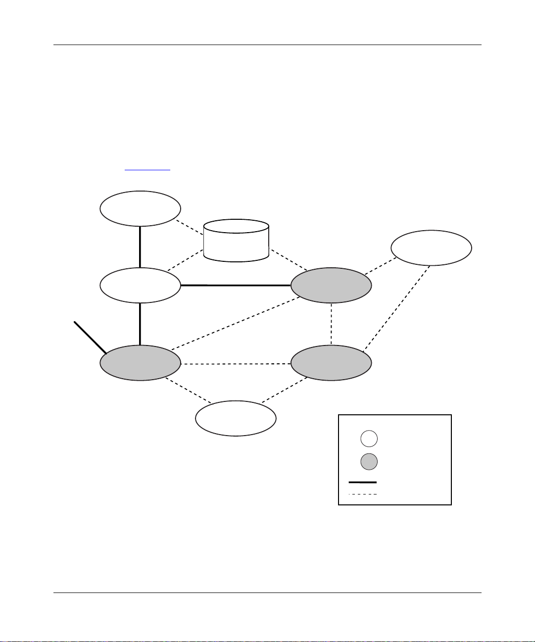
The Bay Networks MPLS implementation consists of three major components:
• Label distribution entity
• MPLS label management (MLM) entity
• Forwarding enti ty
Understanding MPLS
Other
interfaces
Figure 1-1
OSPF/RIP
IP
Forwarding
illustrates the basic MPLS system architec tur e.
Routing
table
LDP
MLM
Driver
Key
MIB
External
component
MPLS
component
Data path
Control path
Figure 1-1. The MPLS System
305754-A Rev 00
ATM0058A
1-3
Page 20

Configuring MPLS Services
Label Distribution Entity
The label dis tribution entity is essentially the implementation of the Label
Distribution Protocol (LDP). LDP is the set of proc edures and mess ages by which
label-switching routers (LSRs) establish label-switched paths (LSPs) through a
network. LDP establishes these paths by mapping network layer routing
information directly to data link layer switched paths.
LDP associates a packet stream with a speci fi c LSP and assigns the LSP a specif ic
label. The label infor mation is distributed betwe en the LSRs and LERs to
maintain stream mapping information.
MPLS Label Management
The MPLS label management (MLM) entity communicates with LDP. It is
responsible for:
• Establishing the de fault VC
• Responding to requests from LDP (for example, requests for a label and
establishing VC communications)
Forwarding
1-4
• Communicating with the ATM driver to set up and tear down VCs
The forwarding entity encapsulates and decapsulates the data that it sends and
receives over the MPLS interface.
Outbound data is delivered to the encapsulation process by the higher layers and
delivered to the lower-level driver for transmission to the MPLS network.
Inbound data is received from the MPLS network by the lower-level driver and
delivered to the decapsulation process, wher e it is stripped of layer 2 protocol
headers. The decapsulation process then passes the inbound data to higher layers
for further processi ng.
305754-A Rev 00
Page 21
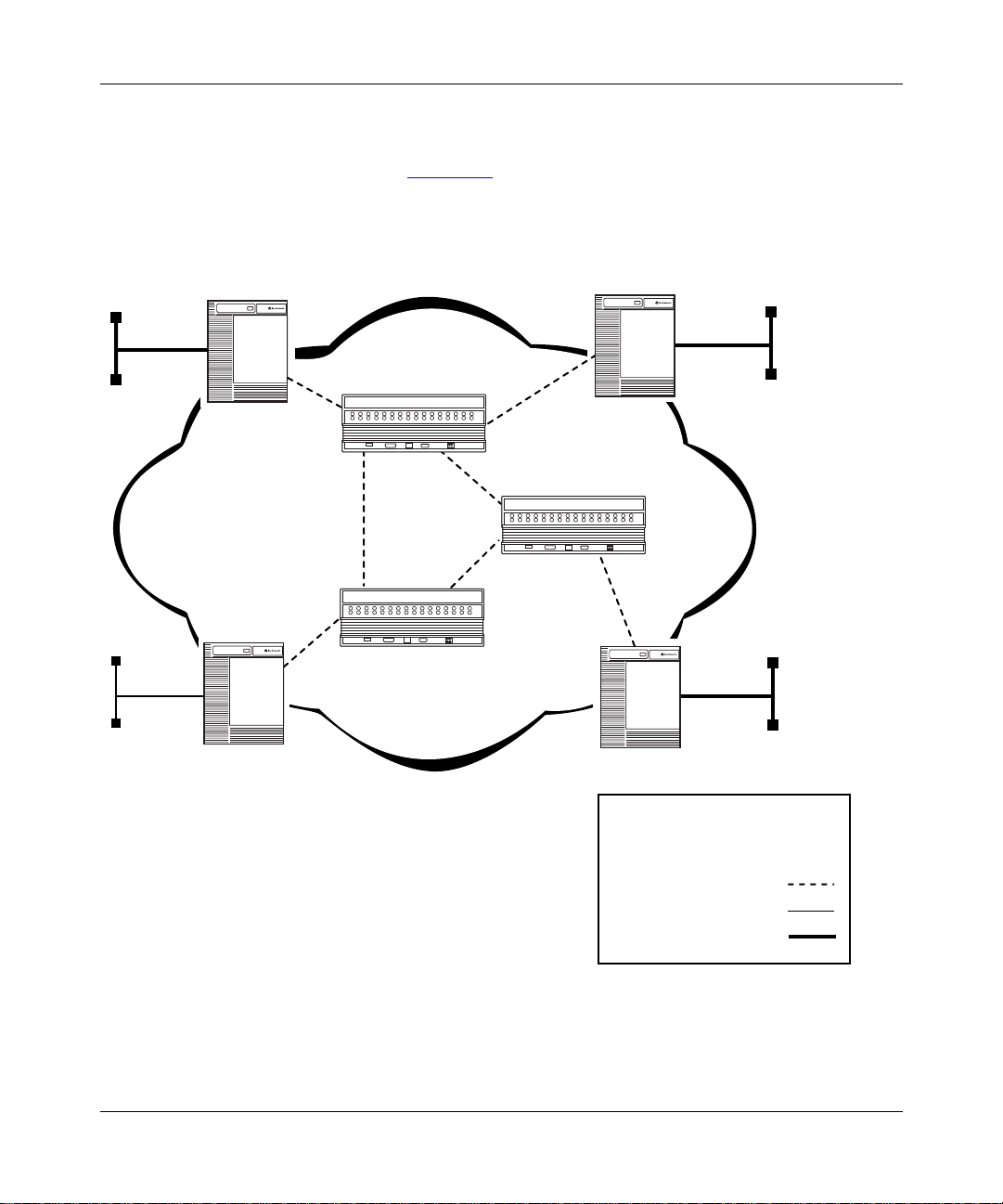
The MPLS Network
The MPLS network (Figure 1-2) consists of two major components:
• Label switching router (LSR)
• Label edge router (LER)
Understanding MPLS
100BASE-T
10BASE-T
LER
MPLS network
LER
100BASE-T
LSR
LER
LSR
LSR
100BASE-T
LER
Key
Label-switching router (LSR)
Label edge router (LER)
Virtual connection
10BASE-T
100BASE-T
Figure 1-2. Sample MPLS Network
305754-A Rev 00
ATM0057A
1-5
Page 22

Configuring MPLS Services
Label Switching Router
A label-switching router (LSR) is a router that contains all label-sw itching
interfaces. The LSR controls MPLS forwarding in the MPLS network. An LSR
performs table lookup on received packets and, based on the packet label,
forwards the packet or packet stream to the specified outgoing inter f ace. The LSR
swaps the labels of the packet headers before transmitting the packets to the
MPLS network.
Note:
An ATM LSR currently consis ts of an ATM switc hing de vice that w orks
with a UNIX UltraSPARC workstation running Solaris and LDP. For
information about how to configure an ATM LSR, refer to the documentation
provided with your switching device.
Label Edge Router
A label edge router (LER) is an LSR that resides between the IP and MPLS
networks. This router performs two generalized functions:
• It receives non-MPLS traffic, labels that traffic, and forwards it to another
label-switching interface.
1-6
• It receives labeled MPLS traffic, strips the label from the packets, and
forwards the traffic over a non-MPLS interface.
Note:
This guide describes how to configure the LER. For information about
how to start M PLS on the router, see Chapter 2, “Starting MPLS.” For
information about how to customize the ATM router interface for MPLS, see
Chapter 3, “Customizing the MPLS Configuration.”
305754-A Rev 00
Page 23

Supported Protocols
MPLS supports the following protocols:
•IP
•RIP
• BGP
• OSPF
For More Information
For more inform ation about MPLS, refer to the following documents:
Black, D. Building Switche d N etworks: Mu ltilayer Switching, Qos, IP Multicast,
Network Policy, and Service-Level Agreements. Reaqding, MA.: Addison-Wesley,
1999.
“LDP Specification,” Andersson, Doolan, Feldman, Fredette, Thomas, Internet
Draft <draft-ietf-mpls-ldp-01.txt>. August, 1998.
Understanding MPLS
305754-A Rev 00
“Multiprotocol Label Switching Architecture,” Callon, Rosen, Viswanathan,
Internet Draft <draft-ietf-mpls-arch-02.txt>. July, 1998.
1-7
Page 24

Configuring MPLS Services
Where to Go Next
Use the following table to determine where to go next.
If you want to Go to
Learn about ATM concepts.
Start MPLS. Chapter 2
Change default settings for MPLS parameters. Chapter 3
Change default settings for ATM interface
parameters.
Change default settings for ATM signaling
parameters.
Change default settings for ATM PVC service record
and PVC parameters.
Change default settings for classical IP service
record parameters.
Change default settings for LAN emulation client
service record parameters.
Change default settings for Multi-Protocol Over ATM
server parameters.
Change default settings for the ATM router
redundancy parameter.
Obtain information about Site Manager parameters. Appendix A
Monitor ATM using the BCC show commands.
Configure NHRP for MPOA services.
Configuring ATM
Services
Configuring ATM
Services
Configuring ATM
Services
Configuring ATM
Services
Configuring ATM
Services
Configuring ATM
Services
Configuring MPOA
Services
Configuring ATM
Services
Configuring ATM
Services
Configuring MPOA
Services
1-8
305754-A Rev 00
Page 25
Chapter 2
Starting MPLS
This chapter describes how to create a basic MPLS configuration by specifying
values for required parameters only and accepting default values for all other
parameters.
You can confi gure MP LS using Si te Manage r. For instruction s on ho w t o star t and
use Site Manager, see Configuring and Managing Routers wit h Site Manager.
For overview information about MPLS, see Chapter 1, “Understanding MPLS.”
You start MPLS on a router using Site Manager by:
Topic Page
Creating an ATM Circuit 2-2
Adding Protocols to an LDP Session Record 2-4
Adding IP Adjacent Hosts 2-6
Defining IP Static Routes for LDP 2-8
Enabling MLM 2-9
Enabling TCP 2-10
Where to Go Next 2-12
305754-A Rev 00
2-1
Page 26
Configuring MPLS Services
Creating an ATM Circuit
MPLS operates only over an ATM circuit. You must create an ATM circ uit before
you can configure MPLS.
To create an ATM circuit, complete the following tasks:
You do this System responds
Site Manager Procedure
1. In the Configuration Manager window,
click on an ATM link module interface
(
).
ATM1
2. Click on OK to accept the default circuit
name.
3. Go to the following section, “Adding an
LDP Session Record,” or go to step 4 to
exit this procedure.
4. Click on
. You return to the Configuration Manager
Done
Adding an LDP Session Record
After you create an ATM circuit over which MPLS can operate, you must add an
LDP session record t o that circ uit . F or infor mati on about crea ting an ATM ci rcuit ,
see “Creating an ATM Circuit
Note:
This release supports only one LDP session record per ATM interface.
The Add Circuit window opens.
The Select Connection Type window
opens.
window.
” on page 2-2.
2-2
305754-A Rev 00
Page 27

Starting MPLS
To add an LDP session record, complete the following tasks:
Site Manager Procedure
You do this System responds
1. In the Configuration Manager window,
click on an ATM link module interface
(
).
ATM1
2. Click on OK to accept the default circuit
name.
3. Click on
4. Click on
5. Click on
6. Set the following parameters:
• Local IP Address
• Remote IP Address
Click on
descriptions beginning on page A-3.
7. Click on OK. The Default VC Record Parameters
8. Click on OK. The Select Protocols window opens.
9. Go to the following section, “Adding
Protocols to the LDP Session,” or go to
step 10 to exit this procedure.
10. Click on
11. Click on
12. Click on
13. Click on
. The Edit MPLS Connector win do w opens .
MPLS
. The LDP Session Records List window
LDP
. The LDP Session Record Parameters
Add
Help
or see the parameter
. You return to the LDP Session Records
Cancel
. You return to the Edit MPLS Connector
Done
. You return to the Select Connection Type
Done
. You return to the Configuration Manager
Done
The Add Circuit window opens.
The Select Connection Type window
opens.
opens.
window opens.
window opens.
List window.
window.
window.
window.
305754-A Rev 00
2-3
Page 28

Configuring MPLS Services
Adding Protocols to an LDP Session Record
You can either add protocols immediately after you create an LDP session, or you
can add protocols to an existing LDP session at any time.
Adding Protocols to the LDP Session
To add protocols to an LDP session record, complete the following tasks:
Site Manager Procedure
You do this System responds
1. In the Select Protocols window, click on IP. A check mark appears in the box for IP.
2. Click on any IP routing protocol that you
want to add.
3. Click on OK. The IP Configuration window opens.
4. Set the following parameters:
• IP Address
• Subnet Mask
Click on
RIP, and OSPF Ser vices
5. Click on OK. For each additional protocol that you
Help
or see
Configuring IP, ARP,
for details.
A check mark app ears in the bo x for each
additional protocol that you select.
The IP address should ma tch the loc al IP
address that you configured for the LDP
session.
selected, the Configuration Manager
displays a protocol-specific window
prompting you for required information.
2-4
6. Click on
7. Click on
8. Click on
Click on
the appropriate protocol-specific guide.
After completing all required protocol
configuration, you return to the LDP
Session Records List wind ow.
. You return to the Edit MPLS Connector
Done
window.
. You return to the Select Connection Type
Done
window.
. You return to the Configuration Manager
Done
window.
for any parameter, or see
Help
305754-A Rev 00
Page 29

Adding Protocols to an Existing Record
To add protocols to an existing LDP session record, complete the following tasks:
Site Manager Procedure
You do this System responds
Starting MPLS
1. In the Configuration Manager window,
click on an ATM link module interface
(
).
ATM1
2. Click on
3. Click on
4. Click on the session record that you
configured.
(Site Manager supports only one LDP
session record.)
5. Click on
6. Choose
7. Click on IP. A check mark appears in the box for IP.
8. Click on any other protocols that you want
to add.
9. Click on OK. The IP Configuration window opens.
10. Set the following parameter s:
• IP Address
• Subnet Mask
Click on
RIP, and OSPF Services
. The Edit MPLS Connector win do w opens .
MPLS
. The LDP Session Records List window
LDP
Protocols
Add/Delete
Help
. The Protocols menu opens.
. The Select Protocols window opens.
or see
Configuring IP, ARP,
for details.
The Select Connection Type window
opens.
opens.
The Protocols menu selection becomes
active.
A check mark appears in the box for each
additional protocol that you select.
The IP address should ma tch the loc al IP
address that you configured for the LDP
session.
(continued)
305754-A Rev 00
2-5
Page 30

Configuring MPLS Services
You do this System responds
11. Click on OK. For each additional protocol that you
12. Click on
13. Click on
14. Click on
. You return to the Edit MPLS Connector
Done
. You return to the Select Connection Type
Done
. You return to the Configuration Manager
Done
Adding IP Adjacent Hosts
Site Manager Procedure
select, the Configuration Manager
displays a protocol-specific window
prompting you for required information.
Click on
the appropriate protocol-specific guide.
After completing all required protocol
configuration, you return to the LDP
Session Records List wind ow.
window.
window.
window.
(continued)
for any parameter, or see
Help
2-6
Caution:
You must configure IP adjacent hosts at the MPLS interface level.
The adjacencies must be specific to the MPLS interface for MPLS to function
properly. Do not configure IP adjacent hosts at the global level.
305754-A Rev 00
Page 31

Starting MPLS
To ad d IP adjacencies to LDP, complete th e following tasks:
Site Manager Procedure
You do this System responds
1. In the Configuration Manager window,
click on an ATM link module interface
(
).
ATM1
2. Click on
3. Click on
4. Click on the session record that you
configured.
(Site Manager supports only one LDP
session record.)
5. Click on
6. Choose
7. Choose
8. Click on
9. Set the following parameters:
• IP Adjacent Host Address
• MAC Address, DLCI, VPI/VCI
• Host Encapsulation
Click on
RIP, and OSPF Services
. The Edit MPLS Connector win do w opens .
MPLS
. The LDP Session Records List window
LDP
Protocols
Edit IP
Adjacent Hosts
Add
Help
. The Protocols menu opens.
. The IP menu opens.
. The IP Adjacent Hosts window opens.
. The IP Configuration window opens.
or see
Configuring IP, ARP,
for details.
The Select Connection Type window
opens.
opens.
The Protocols menu selection becomes
active.
Set the
parameter to the next-hop IP address of
the LSR to which you are connecting.
Set the
parameter to the VPI/VCI value of the
LDP default VC .
IP Adjacent Host Address
MAC Address, DLCI, VPI/VCI
305754-A Rev 00
Set the
to SNAP.
10. Click on OK. You return to the IP Adjacent Hosts
window.
11. Click on
. You return to the LDP Session Records
Done
list window.
Host Encapsulation
parameter
(continued)
2-7
Page 32

Configuring MPLS Services
Site Manager Procedure
You do this System responds
12. Click on
13. Click on
14. Click on
. You return to the Edit MPLS Connector
Done
. You return to the Select Connection Type
Done
. You return to the Configuration Manager
Done
Defining IP Static Routes for LDP
If you intend to use IP sta tic route s ov er MPLS, you must defi ne the IP st atic route
prefix and the route mask for LDP.
Note:
You can configure IP static routes before or after you configure MPLS.
For information on static routes or how to configure them, see Configuring IP,
ARP, RIP, and OSPF Services.
To define L DP static routes, complete the following task s:
(continued)
window.
window.
window.
2-8
Site Manager Procedure
You do this System responds
1. In the Configuration Manager window,
click on an ATM link module interface
(
).
ATM1
2. Click on
3. Click on
4. Click on the session record that you
configured.
(Site Manager allows only one LDP
session record.)
5. Click on
. The Edit MPLS Connector win do w opens .
MPLS
. The LDP Session Records List window
LDP
Static Route
. The LDP Static Route List window opens.
The Select Connection Type window
opens.
opens.
(continued)
305754-A Rev 00
Page 33

Starting MPLS
You do this System responds
6. Click on
7. Set the following parameters:
• Destination Route Prefix
• Route Mask
Click on
descriptions beginning on page A-7.
8. Click on OK. You return to the LDP Static Route List
9. Click on
10. Click on
11. Click on
12. Click on
Enabling MLM
Site Manager Procedure
. The Static Route Parameters window
Add
or see
Help
Done
Done
Done
Done
the parameter
. You return to the LDP Session Records
. You return to the Edit MPLS Connector
. You return to the Select Connection Type
. You return to the Configuration Manager
(continued)
opens.
window.
List window.
window.
window.
window.
305754-A Rev 00
In order for MPLS to operate properly over ATM, you must enable MLM on the
interface.
To enable MLM, complete the following tasks:
Site Manager Procedure
You do this System responds
1. In the Configuration Manager window,
click on an ATM link module interface
(
).
ATM1
2. Click on
3. Click on
. The Edit MPLS Connector win do w opens .
MPLS
. The MLM Parameters window opens.
MLM
The Select Connection Type window
opens.
(continued)
2-9
Page 34

Configuring MPLS Services
You do this System responds
4. Click on
5. Click on
6. Click on
Enabling TCP
For LDP to communicate over the ATM VC, you must enable TCP on the router.
If you plan to create more than 200 LSPs on one slot, you must also increase the
TCP window size to 65,535 bytes.
To enable TCP, complete the following t asks:
You do this System responds
Site Manager Procedure
. Site Manager enables MLM on the
Apply
. You return to the Select Connection Type
Done
. You return to the Configuration Manager
Done
Site Manager Procedure
(continued)
interface. You return to the Edit MPLS
Connector window.
window.
window.
2-10
1. In the Configuration Manager window,
choose
2. Choose
3. Choose
4. Choose
Protocols
Global Protocols
TCP
Create TCP
.
. The Global Protocols menu opens.
. The TCP menu opens.
. Site Manager enables TCP. You return to
The Protocols menu opens.
the Configuration Manager window.
305754-A Rev 00
Page 35

Increasing the TCP Window Size
To increase the TCP window size, complete the following tasks:
You do this System responds
Starting MPLS
Site Manager Procedure
1. In the Configuration Manager window,
choose
2. Choose
3. Choose
4. Choose
5. Set the
parameter to 65,535 bytes. Click on
or see
Services
6. Choose OK. You return to the Configuration Manager
Protocols
Global Protocols
TCP
Global
Max. Window Size (bytes)
Configuring IP, ARP, RIP, and OSPF
for details.
.
. The Global Protocols menu opens.
. The TCP menu opens.
. The Edit TCP Global Parameters window
Help
The Protocols menu opens.
opens.
window.
305754-A Rev 00
2-11
Page 36

Configuring MPLS Services
Where to Go Next
Use the following table to determine where to go next.
If you want to Go to
Learn about ATM concepts.
Learn about MPLS concepts. Chapter 1
Change default settings for MPLS parameters. Chapter 3
Change default settings for ATM interface
parameters.
Change default settings for ATM signaling
parameters.
Change default settings for ATM PVC service record
and PVC parameters.
Change default settings for classical IP service
record parameters.
Change default settings for LAN emulation client
service record parameters.
Change default settings for Multi-Protocol Over ATM
server parameters.
Change default settings for the ATM router
redundancy parameter.
Obtain information about Site Manager parameters. Appendix A
Monitor ATM using the BCC show commands.
Configure NHRP for MPOA services.
Configuring ATM
Services
Configuring ATM
Services
Configuring ATM
Services
Configuring ATM
Services
Configuring ATM
Services
Configuring ATM
Services
Configuring MPOA
Services
Configuring ATM
Services
Configuring ATM
Services
Configuring MPOA
Services
2-12
305754-A Rev 00
Page 37

Chapter 3
Customizing the MPLS Configuration
This chapter describ es how to customize an MPLS config uration and includes the
following information:
Topic Page
Customizing LDP Parameters 3-2
Disabling and Reenabling MLM Administrative Status 3-11
Customizing Default VC Parameters 3-12
Customizing LDP Static Route Parameters 3-29
Deleting MPLS from an Interface 3-32
Where to Go Next 3-33
305754-A Rev 00
For general information about MPLS, see Chapter 1, “Understanding MPLS.”
For information about starting MPLS, see Chapter 2, “Starting MPLS.”
3-1
Page 38

Configuring MPLS Services
Customizing LDP Parameters
LDP is a protocol governing the set of procedures and messages by which
label-switching routers (LSRs) establish label-switched paths (LSPs) through a
network. LDP establishes these paths by mapping network layer routing
information directly to data link layer switched paths.
You can customize the default values for LDP parameters, as described in the
following sections.
Disabling and Reenabling LDP
By default, you enable LDP w hen you add an LDP session to the interface.
However, you can disable and reenable the LDP session at any time. Enable the
session to allow MPLS LDP to operate over the interface. Disable the session to
turn off MPLS LDP on the inte rface.
To disable or reena ble LDP, complete the following tasks:
Site Manager Procedure
3-2
You do this System responds
1. In the Configuration Manager window,
click on the ATM interface (
want to modify.
2. Click on
3. Click on
4. Set the
on
Help
on page A-2.
5. Click on
6. Click on
7. Click on
. The Edit MPLS Connector win do w opens .
MPLS
. The LDP Session Records List window
LDP
Enable/Disable
or see the parameter description
. You return to the Edit MPLS Connector
Done
. You return to the Select Connection Type
Done
. You return to the Configuration Manager
Done
parameter. Click
ATM1
) that you
The Select Connection Type window
opens.
opens.
window.
window.
window.
305754-A Rev 00
Page 39

Changing the Local IP Address
The local IP address identifies the local IP address that LDP uses to establish the
TCP connection to the LSR.
The default address, 0.0.0.0, is useful only under specific circumstances (for
example, whe n using circuitless IP) . In most cases, you must enter a valid IP
address for this inte rface in dotted-decimal notati on. If you sta rted MPLS with the
default IP address of 0.0.0.0, you can change the address.
Note:
Bay Networks recommends that you use the IP address that you used
when configuring the IP protocol on this interface.
To change the local IP address, complete the following tasks:
You do this System responds
Customizing the MPLS Configuration
Site Manager Procedure
1. In the Configuration Manager window,
click on the ATM interface (
want to modify.
2. Click on
3. Click on
4. Set the
Click on
description on page A-3.
5. Click on
6. Click on
7. Click on
. The Edit MPLS Connector win do w opens .
MPLS
. The LDP Session Records List window
LDP
Local IP Address
or see the param eter
Help
. You return to the Edit MPLS Connector
Done
. You return to the Select Connection Type
Done
. You return to the Configuration Manager
Done
) that you
ATM1
parameter.
The Select Connection Type window
opens.
opens.
window.
window.
window.
305754-A Rev 00
3-3
Page 40

Configuring MPLS Services
Specifying a Local TCP Port
The local TCP port number specifies the TCP port that LDP on the label edge
router (LER) uses to establish the TCP connection to the label-switching router
(LSR).
Accept the default, 8192, or enter a TCP port number from 1 to 65,535.
To change the local TCP port number, complete the following tasks:
You do this System responds
Site Manager Procedure
1. In the Configuration Manager window,
click on the ATM interface (
want to modify.
2. Click on
3. Click on
4. Set the
on
Help
on page A-3.
5. Click on
6. Click on
7. Click on
. The Edit MPLS Connector win do w opens .
MPLS
. The LDP Session Records List window
LDP
Local TCP Port
or see the parameter description
. You return to the Edit MPLS Connector
Done
. You return to the Select Connection Type
Done
. You return to the Configuration Manager
Done
parameter. Click
ATM1
) that you
The Select Connection Type window
opens.
opens.
window.
window.
window.
3-4
305754-A Rev 00
Page 41

Specifying a Remote IP Address
The remote IP address parameter specifies the IP address of the interface on the
label-switching router (LSR) that LDP on the label edge router (LER) uses to
establish the TCP connection.
The default address, 0.0.0.0, is useful only under specific circumstances (for
example, whe n using circuitless IP) . In most cases, you must enter a valid IP
address for this inte rface in dotted-decimal notati on. If you sta rted MPLS with the
default IP address of 0.0.0.0, you can change the address.
Note:
Bay Networks recommends that you use the IP address that you used
when configuring the IP protocol on the remote interface.
To change the remote IP address, complete the following tasks:
You do this System responds
Customizing the MPLS Configuration
Site Manager Procedure
305754-A Rev 00
1. In the Configuration Manager window,
click on the ATM interface (
want to modify.
2. Click on
3. Click on
4. Set the
Click on
description on page A-3.
5. Click on
6. Click on
7. Click on
. The Edit MPLS Connector win do w opens .
MPLS
. The LDP Session Records List window
LDP
Remote IP Address
or see the param eter
Help
. You return to the Edit MPLS Connector
Done
. You return to the Select Connection Type
Done
. You return to the Configuration Manager
Done
) that you
ATM1
parameter.
The Select Connection Type window
opens.
opens.
window.
window.
window.
3-5
Page 42

Configuring MPLS Services
Specifying a Remote TCP Port
The remote TCP port number specif ies the remot e TCP port of the l abel-switc hing
router (LSR) that the label edge router (LER) uses to establish the TCP
connection.
Accept the default, 8192, or enter a TCP port number from 1 to 65,535.
To change the remote TCP port number, complete the following tasks:
You do this System responds
Site Manager Procedure
1. In the Configuration Manager window,
click on the ATM interface (
want to modify.
2. Click on
3. Click on
4. Set the
Click on
description on page A-4.
5. Click on
6. Click on
7. Click on
. The Edit MPLS Connector win do w opens .
MPLS
. The LDP Session Records List window
LDP
Remote TCP Port
or see the param eter
Help
. You return to the Edit MPLS Connector
Done
. You return to the Select Connection Type
Done
. You return to the Configuration Manager
Done
) that you
ATM1
parameter.
The Select Connection Type window
opens.
opens.
window.
window.
window.
3-6
305754-A Rev 00
Page 43

Specifying the Routes Configuration Mode
The routes conf igu ratio n mod e spe cif i es what kind of route tabl e LDP uses. When
you accept the default, Auto, MPLS uses either the OSPF or RIP route table.
When you specify Manual, LDP uses static routes.
Note:
The routes configuration mode takes precedence over the protocol that
you set (see “
3-9). This means that when you set the routes configuration mode to Manual,
LDP disregards the protocol setting.
To specify the rout es configuration mode, complete the following tas ks:
You do this System responds
Specifying a Protocol for MPLS Route Configuration” on page
Site Manager Procedure
Customizing the MPLS Configuration
1. In the Configuration Manager window,
click on the ATM interface (
want to modify.
2. Click on
3. Click on
4. Set the
parameter. Click on
parameter description on page A-4.
5. Click on
6. Click on
7. Click on
. The Edit MPLS Connector win do w opens .
MPLS
. The LDP Session Records List window
LDP
Routes Configuration Mode
or see the
Help
. You return to the Edit MPLS Connector
Done
. You return to the Select Connection Type
Done
. You return to the Configuration Manager
Done
ATM1
) that you
The Select Connection Type window
opens.
opens.
window.
window.
window.
305754-A Rev 00
3-7
Page 44

Configuring MPLS Services
Specifying a Hold Time
The hold time is the number of seconds that LDP can wait without receiving a
keepalive packet from its peer entity before considering the LDP session down.
You can accept the default hold time, 40 s eco nds, or specify a hold time from 1 to
240 seconds.
To specify a hold time, complete th e following tasks:
You do this System responds
Site Manager Procedure
1. In the Configuration Manager window,
click on the ATM interface (
want to modify.
2. Click on
3. Click on
4. Set the
or see the parameter description on
Help
page A-5.
5. Click on
6. Click on
7. Click on
. The Edit MPLS Connector win do w opens .
MPLS
. The LDP Session Records List window
LDP
Hold Time
. You return to the Edit MPLS Connector
Done
. You return to the Select Connection Type
Done
. You return to the Configuration Manager
Done
parameter. Click on
ATM1
) that you
The Select Connection Type window
opens.
opens.
window.
window.
window.
3-8
305754-A Rev 00
Page 45
Customizing the MPLS Configuration
Specifying a Protocol for MPLS Route Configuration
You can specify the protocol that LDP uses to configure routes or allow LDP to
use both a protocol and IP static routes.
Accept the default, OSPF, for OSPF routing. Specify RIP to use the routing
information protocol. When using either the OSPF or RIP setting, LDP does not
use any of the IP static routes in the route table.
To use static routes based on the entries in the forwarding information base (FIB)
along with OSPF, specify HYBRIDOSPF. To use static routes along with RIP,
specify HYBRIDRIP.
Note:
The routes configuration mode takes precedence over the protocol that
you set (see “
means that when you set the routes configuration mode to Manual, LDP
disregards the protocol setting.
To specify a protocol for route configuration, complete the following tasks:
Specifying the Routes Configuration Mode” on page 3-7). This
305754-A Rev 00
Site Manager Procedure
You do this System responds
1. In the Configuration Manager window,
click on the ATM interface (
want to modify.
2. Click on
3. Click on
4. Set the
or see the parameter description on
page A-5.
5. Click on
6. Click on
7. Click on
. The Edit MPLS Connector win do w opens .
MPLS
. The LDP Session Records List window
LDP
Protocol
Done
Done
Done
parameter . C lic k on
. You return to the Edit MPLS Connector
. You return to the Select Connection Type
. You return to the Configuration Manager
ATM1
) that you
The Select Connection Type window
opens.
opens.
Help
window.
window.
window.
3-9
Page 46

Configuring MPLS Services
Enabling and Disabling Aggregation
The Aggregation parameter specifies whether or not the label edge router (LER)
recognizes label-switched paths (LSPs) aggregated (combined) over one VC.
Aggregation allows the same label (or VPI/VCI) for many LSPs. Using the same
label for many LSPs i s a nal ogou s to using the same next-hop address for mul ti pl e
routes.
If the LSR is not conf igured to se nd (or does n ot support ) aggre gated LSP s, accep t
the default, Disable. If the LSR sends aggregated LSPs, enable aggregation.
To enable or disable aggregation, co mplete the foll owing tasks:
Site Manager Procedure
You do this System responds
1. In the Configuration Manager window,
click on the ATM interface (
want to modify.
2. Click on
3. Click on
4. Set the
or see the parameter description on
Help
page A-6.
5. Click on
6. Click on
7. Click on
. The Edit MPLS Connector win do w opens .
MPLS
. The LDP Session Records List window
LDP
Aggregation
. You return to the Edit MPLS Connector
Done
. You return to the Select Connection Type
Done
. You return to the Configuration Manager
Done
parameter. Click on
ATM1
) that you
The Select Connection Type window
opens.
opens.
window.
window.
window.
3-10
305754-A Rev 00
Page 47

Customizing the MPLS Configuration
Disabling and Reenabling MLM Administrative Status
MPLS label management (MLM) communicates with LDP. It is responsible for
the following:
• Establishing the default VC (0/32)
• Responding to requests from LDP (for example, requests for a label and
establishing VC communications)
• Communicating with the ATM driver to set up and tear down VCs
By default, MLM is enabled when you apply the default setting. You can disable
and reenable MLM.
To disa ble or reenable MLM, complete the following tasks:
Site Manager Procedure
You do this System responds
1. In the Configuration Manager window,
click on the ATM interface (
want to modify.
2. Click on
3. Click on
4. Set the
or see the parameter description on
Help
page A-6.
5. Click on
6. Click on
7. Click on
. The Edit MPLS Connector win do w opens .
MPLS
. The MLM Parameters window opens.
MLM
Admin Status
. You return to the Edit MPLS Connetor
Done
. You return to the Select Connection Type
Done
. You return to the Configuration Manager
Done
parameter. Click on
ATM1
) that you
The Select Connection Type window
opens.
window.
window.
window.
305754-A Rev 00
3-11
Page 48

Configuring MPLS Services
Customizing Default VC Parameters
The LDP uses a default VC to communicate between peers within the MPLS
network. The following parameters define the default VC.
Disabling and Reenabling Default VC Admin Status
When you start MPLS, the default VC is enabled on the interface. To disable or
reenable the default VC, complete the following tasks:
Site Manager Procedure
You do this System responds
1. In the Configuration Manager window,
click on the ATM interface (
want to modify.
2. Click on
3. Click on
4. Click on
5. Set the
or see the parameter description on
Help
page A-6.
6. Click on OK. You return to the LDP Session Records
7. Click on
8. Click on
9. Click on
. The Edit MPLS Connector win do w opens .
MPLS
. The LDP Session Records List window
LDP
Default VC
Admin Status
Done
Done
Done
. The Default VC Record Parameters
parameter. Click on
. You return to the Edit MPLS Connector
. You return to the Select Connection Type
. You return to the Configuration Manager
ATM1
) that you
The Select Connection Type window
opens.
opens.
window opens.
List window.
window.
window.
window.
3-12
305754-A Rev 00
Page 49

Specifying the Default VCL VPI Number
The default VCL VPI number identifies the virtual path of the MPLS default VC.
The VPI is part of the cell header. The header can contain a maximum of 8 VPI
bits for a user-to-network (UNI) connection. This bit range allows for path
identifiers from 0 to 255.
To specify a VPI number for the default VCL, complete the following tasks:
Site Manager Procedure
You do this System responds
Customizing the MPLS Configuration
1. In the Configuration Manager window,
click on the ATM interface (
want to modify.
2. Click on
3. Click on
4. Click on
5. Set the
on
Help
on page A-8.
6. Click on OK. You return to the LDP Session Records
7. Click on
8. Click on
9. Click on
. The Edit MPLS Connector win do w opens .
MPLS
. The LDP Session Records List window
LDP
Default VC
Default Vcl VPI
or see the parameter description
Done
Done
Done
. The Default VC Record Parameters
parameter. Click
. You return to the Edit MPLS Connector
. You return to the Select Connection Type
. You return to the Configuration Manager
ATM1
) that you
The Select Connection Type window
opens.
opens.
window opens.
List window.
window.
window.
window.
305754-A Rev 00
3-13
Page 50

Configuring MPLS Services
Specifying the Default VCL VCI Number
The default VCL VCI number identifies the virtual channel of the MPLS default
VC. The VCI is part of the cell header. The header can contain a maximum of 16
VCI bits. This bit range allows for channel identifiers from 32 to 65,535.
To change theVCI number for the default VCL, complete the following tasks:
Site Manager Procedure
You do this System responds
1. In the Configuration Manager window,
click on the ATM interface (
want to modify.
2. Click on
3. Click on
4. Click on
5. Set the
on
Help
on page A-9.
6. Click on OK. You return to the LDP Session Records
7. Click on
8. Click on
9. Click on
. The Edit MPLS Connector win do w opens .
MPLS
. The LDP Session Records List window
LDP
Default VC
Default Vcl VCI
or see the parameter description
Done
Done
Done
. The Default VC Record Parameters
parameter. Click
. You return to the Edit MPLS Connector
. You return to the Select Connection Type
. You return to the Configuration Manager
ATM1
) that you
The Select Connection Type window
opens.
opens.
window opens.
List window.
window.
window.
window.
3-14
305754-A Rev 00
Page 51

Specifying the Default VC VPI Range
The default VC VPI range identifies the virtual path that MPLS can use when
creating SVCs. The VPI is part of the cell header. The header can contain a
maximum of 8 VPI bits for a UNI connection. This bit range allows for path
identifiers from 0 to 255.
To specify a VPI range number, complete th e following tasks:
Site Manager Procedure
You do this System responds
Customizing the MPLS Configuration
1. In the Configuration Manager window,
click on the ATM interface (
want to modify.
2. Click on
3. Click on
4. Click on
5. Set the
or see the parameter description on
Help
page A-9.
6. Click on OK. You return to the LDP Session Records
7. Click on
8. Click on
9. Click on
. The Edit MPLS Connector win do w opens .
MPLS
. The LDP Session Records List window
LDP
Default VC
VC Range VPI
Done
Done
Done
. The Default VC Record Parameters
parameter . Cl ick on
. You return to the Edit MPLS Connector
. You return to the Select Connection Type
. You return to the Configuration Manager
ATM1
) that you
The Select Connection Type window
opens.
opens.
window opens.
List window.
window.
window.
window.
305754-A Rev 00
3-15
Page 52

Configuring MPLS Services
Specifying the Default VC VCI Minimum Range
The default VC VCI minimum range identifies the lowest virtual channel numbe r
that MPLS can use when creating SVCs. The VCI is part of the cell header. The
header can contain a maximum of 16 VCI bits. This bit range allows for channel
identifiers from 32 to 65,535.
Note:
The default VC (3-14) cannot be in the default VC VCI minimum/
maximum range.
To spec ify a minimum VCI number, complete the following tasks:
Site Manager Procedure
You do this System responds
1. In the Configuration Manager window,
click on the ATM interface (
want to modify.
2. Click on
3. Click on
4. Click on
5. Set the
parameter. Click on
parameter description on page A-9.
6. Click on OK. You return to the LDP Session Records
7. Click on
8. Click on
9. Click on
. The Edit MPLS Connector win do w opens .
MPLS
. The LDP Session Records List window
LDP
Default VC
Vc Range Minimum VCI
Done
Done
Done
. The Default VC Record Parameters
or see the
Help
. You return to the Edit MPLS Connector
. You return to the Select Connection Type
. You return to the Configuration Manager
ATM1
) that you
The Select Connection Type window
opens.
opens.
window opens.
List window.
window.
window.
window.
3-16
305754-A Rev 00
Page 53

Customizing the MPLS Configuration
Specifying the Default VC VCI Maximum Range
The default VC VCI maxi mum range ident if ie s the lar ge st virtual ch annel number
that MPLS can use when creating SVCs. The VCI is part of the cell header. The
header can contain a maximum of 16 VCI bits. This bit range allows for channel
identifiers from 32 to 65,535.
To spec ify a maximum VCI number, complete the following ta sks:
Site Manager Procedure
You do this System responds
1. In the Configuration Manager window,
click on the ATM interface (
want to modify.
2. Click on
3. Click on
4. Click on
5. Set the
parameter. Click on
parameter description on page A-10.
6. Click on OK. You return to the LDP Session Records
7. Click on
8. Click on
9. Click on
. The Edit MPLS Connector win do w opens .
MPLS
. The LDP Session Records List window
LDP
Default VC
Vc Range Maximum VCI
Done
Done
Done
. The Default VC Record Parameters
or see the
Help
. You return to the Edit MPLS Connector
. You return to the Select Connection Type
. You return to the Configuration Manager
ATM1
) that you
The Select Connection Type window
opens.
opens.
window opens.
List window.
window.
window.
window.
305754-A Rev 00
3-17
Page 54

Configuring MPLS Services
Modifying Default VC Traffic Parameters
You can modify the following transmit and receive traffic parameters for the
MPLS default VC:
• Peak cell rate (PCR)
• Sustainable cell rate (SCR)
• Maximum burst size (MBS)
For additional information about traffic parameters, see the appropriate section in
Configuring ATM Services.
Setting the Default VC Transmit PCR
The transmit peak cell rate (PCR) specifies the upper traffic limit, in cells/s, that
the MPLS egress connection can submit. The default value, 0, indicates that the
PCR is attempting to run at l ine rate.
To change the transmit PCR for the default VC, complete the following tasks:
3-18
Site Manager Procedure
You do this System responds
1. In the Configuration Manager window,
click on the ATM interface (
want to modify.
2. Click on
3. Click on
4. Click on
5. Set the
Click on
description on page A-10.
6. Click on OK. You return to the LDP Session Records
7. Click on
. The Edit MPLS Connector win do w opens .
MPLS
. The LDP Session Records List window
LDP
Default VC
Xmt Peak Cell Rate
Help
Done
. The Default VC Record Parameters
or see the param eter
. You return to the Edit MPLS Connector
) that you
ATM1
parameter.
The Select Connection Type window
opens.
opens.
window opens.
List window.
window.
(continued)
305754-A Rev 00
Page 55

Customizing the MPLS Configuration
Site Manager Procedure
You do this System responds
8. Click on
9. Click on
. You return to the Select Connection Type
Done
. You return to the Configuration Manager
Done
(continued)
window.
window.
Setting the Default VC Transmit SCR
The transmit sustainable cell rate (SCR) specifies the upper limit of the ATM
connection conforming average rate on the transmitting side. The average rate
equals the total number of cells transmitted, divided by the duration of the
connection. The default value, 0, indicates that the transmit SCR is off.
Using the SCR, you can define the future cell flow of a VC in greater detail than
by using only the peak cell rate.
The SCR maps directly to the minimum cell rate (MCR). The MCR defines the
minimum amount of guaranteed bandwidth allowed for the default VC on the
ATM line.
When setting the SCR, keep the following in mind:
305754-A Rev 00
• To be useful, the SCR must not exceed the PCR.
• If you know the average rate, set the SCR approximately 10 percent higher
than this value.
• VCs may fail to operate with SCR values lower than 128 cells/s.
• Entering 0 for the SCR turns off this function.
After you determine the tr ansmis sion ra te of you r ATM device, set the sust ainabl e
cell rate within the specified range.
3-19
Page 56

Configuring MPLS Services
To change the transmit SCR for the default VC, complete the following tasks:
You do this System responds
Site Manager Procedure
1. In the Configuration Manager window,
click on the ATM interface (
want to modify.
2. Click on
3. Click on
4. Click on
5. Set the
parameter. Click on
parameter description on page A-11.
6. Click on OK. You return to the LDP Session Records
7. Click on
8. Click on
9. Click on
. The Edit MPLS Connector win do w opens .
MPLS
. The LDP Session Records List window
LDP
Default VC
Xmit Sustainable Cell Rate
Done
Done
Done
. The Default VC Record Parameters
or see the
Help
. You return to the Edit MPLS Connector
. You return to the Select Connection Type
. You return to the Configuration Manager
ATM1
) that you
The Select Connection Type window
opens.
opens.
window opens.
List window.
window.
window.
window.
Setting the Default VC Transmit MBS
3-20
The transmit maximum burst size (MBS) specifies the maximum number of
sequential cells that the default VC can transmit at the peak cell rate before the VC
must relinquish bandwidth to other VCs. By default, the MBS is 40 cells.
However, you can set the MBS to any value from 1 to 65,535.
When you set the MBS, you should select a value larger than the largest packet
that the default VC can transmit (that is, the size of the Maximum AAL CPCS
Transmit SDU). For example, if your VC accepts packets that are less than 4,608
bytes long, set your MBS value from 45 to 50 cells.
305754-A Rev 00
Page 57

Customizing the MPLS Configuration
To change the transmit burst size for the default VC, complete the following tasks :
Site Manager Procedure
You do this System responds
1. In the Configuration Manager window,
click on the ATM interface (
want to modify.
2. Click on
3. Click on
4. Click on
5. Set the
on
Help
on page A-12.
6. Click on OK. You return to the LDP Session Records
7. Click on
8. Click on
9. Click on
. The Edit MPLS Connector win do w opens .
MPLS
. The LDP Session Records List window
LDP
Default VC
Xmit Burst Size
or see the parameter description
Done
Done
Done
. The Default VC Record Parameters
parameter. Click
. You return to the Edit MPLS Connector
. You return to the Select Connection Type
. You return to the Configuration Manager
ATM1
) that you
The Select Connection Type window
opens.
opens.
window opens.
List window.
window.
window.
window.
305754-A Rev 00
3-21
Page 58

Configuring MPLS Services
Setting the Default VC Receive PCR
The transmit peak cell rate (PCR) specifies the upper traffic limit, in cells/s, that
the MPLS ingress connection can accept. The default value, 0, indicates that the
PCR is attempting to run at l ine rate.
To change the receive PCR for the default VC, complete the following tasks:
You do this System responds
Site Manager Procedure
1. In the Configuration Manager window,
click on the ATM interface (
want to modify.
2. Click on
3. Click on
4. Click on
5. Set the
Click on
description on page A-13.
6. Click on OK. You return to the LDP Session Records
7. Click on
8. Click on
9. Click on
. The Edit MPLS Connector win do w opens .
MPLS
. The LDP Session Records List window
LDP
Default VC
Rcv Peak Cell Rate
Help
Done
Done
Done
. The Default VC Record Parameters
or see the param eter
. You return to the Edit MPLS Connector
. You return to the Select Connection Type
. You return to the Configuration Manager
) that you
ATM1
parameter.
The Select Connection Type window
opens.
opens.
window opens.
List window.
window.
window.
window.
Setting the Default VC Receive SCR
3-22
The receive sustainable cell rate (SCR) specifies the upper limit of the ATM
connection conforming a v erage rate on th e recei ving si de. The av erage rate equals
the total number of cells transmitted, divided by the duration of the connection.
The default value, 0, indicates that the transmit SCR is off.
Using the SCR, you can define the future cell flow of a VC in greater detail than
by using only the peak cell rate.
305754-A Rev 00
Page 59

Customizing the MPLS Configuration
The SCR maps directly to the minimum cell rate (MCR). The MCR defines the
minimum amount of guaranteed bandwidth allowed for the default VC on the
ATM line.
When setting the SCR, keep the following in mind:
• To be useful, the SCR must not exceed the PCR.
• If you know the average rate, set the SCR approximately 10 percent higher
than this value.
• VCs may fail to operate with SCR values lower than 128 cells/s.
• Entering 0 for the SCR turns off this function.
After you determine the tr ansmis sion ra te of you r ATM device, set the sust ainabl e
cell rate within the specified range.
To change the receive SCR for the default VC, complete the following tasks:
Site Manager Procedure
You do this System responds
305754-A Rev 00
1. In the Configuration Manager window,
click on the ATM interface (
want to modify.
2. Click on
3. Click on
4. Click on
5. Set the
parameter. Click on
parameter description on page A-13.
6. Click on OK. You return to the LDP Session Records
7. Click on
8. Click on
9. Click on
. The Edit MPLS Connector win do w opens .
MPLS
. The LDP Session Records List window
LDP
Default VC
Rcv Sustainable Cell Rate
Done
Done
Done
. The Default VC Record Parameters
or see the
Help
. You return to the Edit MPLS Connector
. You return to the Select Connection Type
. You return to the Configuration Manager
ATM1
) that you
The Select Connection Type window
opens.
opens.
window opens.
List window.
window.
window.
window.
3-23
Page 60

Configuring MPLS Services
Setting the Default VC Receive MBS
The receive maximum burst size (MBS) specifies the maximum number of
sequential cell s t hat the default VC can receiv e at the peak cell rate before the VC
must relinquish bandwidth to other VCs.
When you set the MBS, you should select a value larger than the largest packet
that your default VC can receive (that is, the size of the Maximum AAL CPCS
transmit SDU). For example, if your VC accepts packets that are less than 4,608
bytes long, set your MBS value from 45 to 50 cells.
To change the receive MBS for the default VC, complete the following tasks:
You do this System responds
Site Manager Procedure
1. In the Configuration Manager window,
click on the ATM interface (
want to modify.
2. Click on
3. Click on
4. Click on
5. Set the
on
Help
on page A-14.
6. Click on OK. You return to the LDP Session Records
7. Click on
8. Click on
9. Click on
. The Edit MPLS Connector win do w opens .
MPLS
. The LDP Session Records List window
LDP
Default VC
Rcv Burst Size
or see the parameter description
Done
Done
Done
. The Default VC Record Parameters
parameter. Click
. You return to the Edit MPLS Connector
. You return to the Select Connection Type
. You return to the Configuration Manager
ATM1
) that you
The Select Connection Type window
opens.
opens.
window opens.
List window.
window.
window.
window.
3-24
305754-A Rev 00
Page 61

Customizing the MPLS Configuration
Modifying the Default VC Maximum AAL CPCS SDU Size
The maximum AAL CPCS SDU value defines the maximum packet size in bytes
that you intend the default VC to transmit or receive.
Setting the Transmit SDU Size
The maximum AAL CPCS transmit SDU size specifies the maximum packet size
in bytes that you intend this VC to transmit. Bay Networks recommends that you
accept the default value of 4,608 bytes. Most packets fall well within this limit.
To change the transmit AAL CPCS SDU size, complete the following tasks:
Site Manager Procedure
You do this System responds
1. In the Configuration Manager window,
click on the ATM interface (
want to modify.
2. Click on
3. Click on
4. Click on
5. Set the
parameter. Click on
parameter description on page A-15.
6. Click on OK. You return to the LDP Session Records
7. Click on
8. Click on
9. Click on
. The Edit MPLS Connector win do w opens .
MPLS
. The LDP Session Records List window
LDP
Default VC
AAL Cpcs Transmit Sdu Size
Done
Done
Done
. The Default VC Record Parameters
or see the
Help
. You return to the Edit MPLS Connector
. You return to the Select Connection Type
. You return to the Configuration Manager
ATM1
) that you
The Select Connection Type window
opens.
opens.
window opens.
List window.
window.
window.
window.
305754-A Rev 00
3-25
Page 62

Configuring MPLS Services
Setting the Receive SDU Size
The maximum AAL CPCS receive SDU size specifies the maximum packet size
in bytes that you intend this VC to receive. Bay Networks recommends that you
accept the default value of 4,608 bytes. Most packets fall well within this limit.
To change the receive AAL CPCS SDU size, complete the following tasks:
You do this System responds
Site Manager Procedure
1. In the Configuration Manager window,
click on the ATM interface (
want to modify.
2. Click on
3. Click on
4. Click on
5. Set the
parameter. Click on
parameter description on page A-15.
6. Click on OK. You return to the LDP Session Records
7. Click on
8. Click on
9. Click on
. The Edit MPLS Connector win do w opens .
MPLS
. The LDP Session Records List window
LDP
Default VC
AAL Cpcs Receive Sdu Size
Done
Done
Done
. The Default VC Record Parameters
or see the
Help
. You return to the Edit MPLS Connector
. You return to the Select Connection Type
. You return to the Configuration Manager
ATM1
) that you
The Select Connection Type window
opens.
opens.
window opens.
List window.
window.
window.
window.
3-26
305754-A Rev 00
Page 63

Specifying the AAL Encapsulation Type
The AAL encapsulation type specifies the data encapsulation type for the default
VC and all VC connections. The default encapsulation type is LLCENCAPS.
To change the AAL encapsulation type, complete the following tasks:
Site Manager Procedure
You do this System responds
Customizing the MPLS Configuration
1. In the Configuration Manager window,
click on the ATM interface (
want to modify.
2. Click on
3. Click on
4. Click on
5. Set the
Click on
description on page A-16.
6. Click on OK. You return to the LDP Session Records
7. Click on
8. Click on
9. Click on
. The Edit MPLS Connector win do w opens .
MPLS
. The LDP Session Records List window
LDP
Default VC
AAL Encaps Type
Help
Done
Done
Done
. The Default VC Record Parameters
or see the param eter
. You return to the Edit MPLS Connector
. You return to the Select Connection Type
. You return to the Configuration Manager
) that you
ATM1
parameter.
The Select Connection Type window
opens.
opens.
window opens.
List window.
window.
window.
window.
305754-A Rev 00
3-27
Page 64

Configuring MPLS Services
Specifying the Default VC Transmit QOS Class
This parameter is a placeholder for future releases; it does not currently perform
any function on the router. Accept the default, CLASS3, for this parameter.
Specifying the Default VC Receive QOS Class
This parameter is a placeholder for future releases; it does not currently perform
any function on the router. Accept the default, CLASS3, for this parameter.
Specifying the Default VC AAL Type
This parameter is a placeholder for future releases; it does not currently perform
any function on the router. Accept the default, TYPE5, for this parameter.
Specifying the Default VC Congestion Indication
This parameter is a placeholder for future releases; it does not currently perform
any function on the router. Accept the default, OFF, for this parameter.
Enabling and Disabling the Default VC Cell Loss Priority
This parameter is a placeholder for future releases; it does not currently perform
any function on the router. Accept the default, OFF, for this parameter.
Enabling and Disabling Default VC Transmit Tagging
This parameter is a placeholder for future releases; it does not currently perform
any function on the router. Accept the default, OFF, for this parameter.
Enabling and Disabling Default VC Receive Tagging
This parameter is a placeholder for future releases; it does not currently perform
any function on the router. Accept the default, OFF, for this parameter.
3-28
305754-A Rev 00
Page 65

Customizing the MPLS Configuration
Customizing LDP Static Route Parameters
A static route is a manually configured route that specifies the transmission path
that a datagram mus t fol low, base d on the datagram’s des ti nat ion address. A static
route specif ies a tran smission path t o another net work. You configure a static rout e
when you want to restrict datagrams to paths that you specifically configure.
MPLS can use static routes to distribute LDP information throughout the MPLS
network.
If you intend to use IP sta tic route s ov er MPLS, you must defi ne the IP st atic route
prefix and the route mask for LDP. Defining the route prefix and mask does not
configure the static route. Instead, these parameters provide information to LDP
about the static routes that you configure.
Note:
You can configure IP static routes before or after you configure MPLS.
For information about static routes or how to configure them, see Configuring
IP, ARP, RIP, and OSPF Services.
The following parameters define the use of static routes by M PLS.
Enabling and Disabling Static Routes
By default, static routes are disabled on the MPLS interface. Accept the default,
Disable, if you do not want MPLS to use LDP static routes over the interface.
Specify Enable for MPLS to use LDP static routes over the interface.
To enable and disable LDP static routes, complete the following tasks:
Site Manager Procedure
You do this System responds
1. In the Configuration Manager window,
305754-A Rev 00
click on the ATM interface (
want to modify.
2. Click on
3. Click on
4. Click on
. The Edit MPLS Connector win do w opens .
MPLS
. The LDP Session Records List window
LDP
Static Route
. The LDP Static Route List window opens.
ATM1
) that you
The Select Connection Type window
opens.
opens.
(continued)
3-29
Page 66

Configuring MPLS Services
Site Manager Procedure
You do this System responds
5. Select the static route that you want to
modify.
6. Set the
on
on page A-7.
7. Click on OK. You return to the LDP Static Route List
8. Click on
9. Click on
10. Click on
11. Click on
Enable/Disable
or see the parameter description
Help
. You return to the LDP Session Records
Done
. You return to the Edit MPLS Connector
Done
. You return to the Select Connection Type
Done
. You return to the Configuration Manager
Done
parameter. Click
Specifying a Destination Route Prefix
The destination route prefix is a form of classless inter-domain routing address.
The route prefix specifies the IP address of the destination network that you want
to statically configure.
(continued)
window.
List window.
window.
window.
window.
3-30
An example of a route prefix is 141.251.69.0, where the network portion is
represented by first three octets (141.251.69) and the host portion by any value
that appears in the last octet (0).
To specify a destin ation route prefix, complete the following tasks:
Site Manager Procedure
You do this System responds
1. In the Configuration Manager window,
click on the ATM interface (
want to modify.
2. Click on
. The Edit MPLS Connector win do w opens .
MPLS
ATM1
) that you
The Select Connection Type window
opens.
(continued)
305754-A Rev 00
Page 67

Customizing the MPLS Configuration
Site Manager Procedure
You do this System responds
3. Click on
4. Click on
5. Select the static route that you want to
modify.
6. Set the
parameter. Click on
parameter description on page A-7.
7. Click on OK. You return to the LDP Static Route List
8. Click on
9. Click on
10. Click on
11. Click on
. The LDP Session Records List window
LDP
Static Route
Destination Route Prefix
Done
Done
Done
Done
. The LDP Static Route List window opens.
or see the
Help
. You return to the LDP Session Records
. You return to the Edit MPLS Connector
. You return to the Select Connection Type
. You return to the Configuration Manager
(continued)
opens.
window.
List window.
window.
window.
window.
Specifying a Route Mask
The destination route mask specifies the IP route mask that you want the route
prefix to use.
To specify the rout e mask, comple te the following tasks:
You do this System responds
1. In the Configuration Manager window,
click on the ATM interface (
want to modify.
2. Click on
3. Click on
305754-A Rev 00
MPLS
. The LDP Session Records List window
LDP
Site Manager Procedure
The Select Connection Type window
) that you
ATM1
. The Edit MPLS Connector win do w opens .
opens.
opens.
(continued)
3-31
Page 68

Configuring MPLS Services
Site Manager Procedure
You do this System responds
4. Click on
5. Click on the static route that you want to
modify.
6. Set the
Help
page A-7.
7. Click on OK. You return to the LDP Static Route List
8. Click on
9. Click on
10. Click on
11. Click on
Static Route
Route Mask
or see the parameter description on
Done
Done
Done
Done
. The LDP Static Route List window opens.
parameter. Click on
. You return to the LDP Session Records
. You return to the Edit MPLS Connector
. You return to the Select Connection Type
. You return to the Configuration Manager
Deleting MPLS from an Interface
(continued)
window.
List window.
window.
window.
window.
3-32
You cannot delete MPLS globally from the router; you must delete it from each
individual interface. To delete MPLS from the interface using Site Manager,
complete the following tasks:
Site Manager Procedure
You do this System responds
1. In the Configuration Manager window,
click on an ATM link module interface
(
).
ATM1
2. Click on
3. Click on
Delete MPLS
. Site Manager deletes MPLS from the
Yes
. Site Manager asks whether you really
The Select Connection Type window
opens.
want to delete MPLS from the interface.
interface. You return to the Configuration
Manager window.
305754-A Rev 00
Page 69

Where to Go Next
Use the following table to determine where to go next.
If you want to Go to
Customizing the MPLS Configuration
Learn about ATM concepts.
Learn about MPLS concepts. Chapter 1
Start MPLS. Chapter 2
Change default settings for ATM interface
parameters.
Change default settings for ATM signaling
parameters.
Change default settings for ATM PVC service record
and PVC parameters.
Change default settings for classical IP service
record parameters.
Change default settings for LAN emulation client
service record parameters.
Change default settings for Multi-Protocol Over ATM
server parameters.
Change default settings for the ATM router
redundancy parameter.
Obtain information about Site Manager parameters. Appendix A
Monitor ATM using the BCC show commands.
Configure NHRP for MPOA services.
Configuring ATM
Services
Configuring ATM
Services
Configuring ATM
Services
Configuring ATM
Services
Configuring ATM
Services
Configuring ATM
Services
Configuring MPOA
Services
Configuring ATM
Services
Configuring ATM
Services
Configuring MPOA
Services
305754-A Rev 00
3-33
Page 70

Page 71

Appendix A
Site Manager Pa rameters
After you enable an ATM circuit, you can use Site Manager to access MPLS
parameters.
This appendix contains the Site Manager parameter descriptions for MPLS
services. You can display the same information using Site Manager online Help.
This appendix contains the following information:
Topic Page
Accessing MPLS Parameters A-1
LDP Parameters A-2
MLM Parameter A-6
Static Route Parameters A-7
Default VC Parameters A-8
Accessing MPLS Parameters
You access MPLS parameters from the Edit MPLS Connector wi ndo w, which acts
as a control access point for all MPLS parameters. This window provides
information specific to each individual MPLS interface.
For any given interface, the Edit MPLS Connector window provides two buttons:
•LDP
•MLM
By clicking on one of these buttons, you can access and edit the parameters
associated with that specific MPLS interface.
305754-A Rev 00
A-1
Page 72

Configuring MPLS Services
To access parameters from the Edit MPLS Connector window:
1.
In the Configuration Manager window, clic k on an ATM link module
interface (labeled ATM1).
The Select Connection Type window opens.
2.
Click on MPLS.
The Edit MPLS Connector window opens.
3.
Click on the appropriate attribute category.
Note:
You cannot run both ATM and MPLS on the same ATM interface.
LDP Parameters
The following parameters define the LDP.
Parameter: Enable/Disable
Path: Configuration Manager > Circuits > Edit Circuits >
Edit
>
Default: Enable
Options: Enable
Disable
|
Function: Enables or disables the Label Distribution Protocol (LDP) for this MPLS
interface.
Instructions: Accept the defaul t, Enable,
to allow MPLS LDP to operate over the interface.
Disable th e session to turn off MPLS LDP on the interface.
MIB Object ID: 1.3.6.1.4.1.18.3.5.9.15.1.1.2
A-2
MPLS
>
305754-A Rev 00
LDP
Page 73

Parameter: Local IP Address
Path: Configuration Manager > Circuits > Edit Circuits > Edit > MPLS > LDP
Default: 0.0.0.0
Options: Any valid IP address
Function:
Identifies the local IP address that LDP uses to establish the TCP connection to
the LSR.
Instructions: Enter the IP addr ess in dotted-de cimal notation .
you use the IP address that you used when configuring the IP protocol on this
interface.
You can, however, accept the default value, 0.0.0.0, under specific
circumstances (for example, if you are using circuitless IP).
MIB Object ID: 1.3.6.1.4.1.18.3.5.9.15.1.1.6
Parameter: Local TCP Port
Path: Configuration Manager > Circuits > Edit Circuits > Edit > MPLS > LDP
Default: 8192
Options: 1 to 65535
Function: S
pecifies the TCP port number that LDP on the label edge router (LER) uses to
establish the TCP connection to the label-switching router (LSR).
Instructions:
Accept the default, 8192, or enter a TCP port number from 1 to 65,535.
MIB Object ID: 1.3.6.1.4.1.18.3.5.9.15.1.1.7
Site Manager Parameters
Bay Networks reco mmends that
Parameter: Remote IP Address
Path: Configuration Manager > Circuits > Edit Circuits > Edit > MPLS > LDP
Default: 0.0.0.0
Options: Any valid IP address
Function: S
pecifies the IP addres s of th e i nterf ac e on the la bel-s witchi ng rout er (LSR) t hat
LDP on the label edge router (LER) uses to establish the TCP connection
Instructions: Enter the IP addr ess in dotted-de cimal notation .
you use the IP address that you used when configuring the IP protocol on the
remote interface.
You can, however, accept the default value, 0.0.0.0, under
specific circum stances (for example, if you are using circuitless IP).
MIB Object ID: 1.3.6.1.4.1.18.3.5.9.15.1.1.8
305754-A Rev 00
.
Bay Networks reco mmends that
A-3
Page 74
Configuring MPLS Services
Parameter: Remote TCP Port
Path: Configuration Manager > Circuits > Edit Circuits > Edit > MPLS > LDP
Default: 8192
Options: 1 to 65535
Function: S
pecifies the remote TCP port number of the label-switching router (LSR) that
the label edge router (LER) uses to establish the TCP connection.
Instructions:
Accept the default, 8192, or enter a TCP port number from 1 to 65,535.
MIB Object ID: 1.3.6.1.4.1.18.3.5.9.15.1.1.9
Parameter: Routes Configuration Mode
Path: Configuration Manager > Circuits > Edit Circuits > Edit > MPLS > LDP
Default: AUTO
Options: AUTO
Function: S
pecifies what kind of rou te table LDP uses. When you a ccept the defaul t, Auto,
MANUAL
|
MPLS uses either the OSPF or RIP rou te table. When you specify Manu al, LDP
uses static routes.
Instructions: Accept the default, AUTO, if you want MPLS to configure routes using OSPF
or RIP. Specify MANUAL if you want MPLS to use static routes.
MIB Object ID: 1.3.6.1.4.1.18.3.5.9.15.1.1.10
A-4
The routes configuration mode takes precedence over the protocol that
Note:
you set (see “
Protocol” on page A-5) . Thi s means that when you set the routes
configuration mode to Manual, LDP disregards the protocol setting.
305754-A Rev 00
Page 75

Parameter: Hold Time
Path: Configuration Manager > Circuits > Edit Circuits > Edit > MPLS > LDP
Default: 40
Options: 1 to 240
Function: S
pecifies the number of seconds that LDP can wait without receiving a
keepalive packet from its peer entity before considering the LDP session down.
Instructions: A
ccept the default hold time, 40 seconds, or specify a hold time from 1 to 240
seconds.
MIB Object ID: 1.3.6.1.4.1.18.3.5.9.15.1.1.11
Parameter: Protocol
Path: Configuration Manager > Circuits > Edit Circuits > Edit > MPLS > LDP
Default: OSPF
Options: OSPF
Function: S
RIP | OTHER
|
pecifies the protocol that LDP uses to configure routes or allows LDP to use
both a protocol and IP static routes.
Instructions:
Accept the default, OSPF, for OSPF routing. Specify RIP to use the Routing
Information Protocol. By using either the OSPF or RIP setting, LDP does not
use any of the IP static routes in the route table.
To use static routes based on the entries in the forwarding information base
(FIB) along with OSPF, specify HYBRIDOSPF. To use static routes along with
RIP, specify HYBRIDRIP.
MIB Object ID: 1.3.6.1.4.1.18.3.5.9.15.1.1.12
Site Manager Parameters
305754-A Rev 00
The routes configuration mode takes precedence over the protocol that
Note:
you set (see “
Routes Configuration Mode” on page A-4). This means that
when you set the routes configuration mode to Manual, LDP disregards the
protocol setting.
A-5
Page 76

Configuring MPLS Services
Parameter: Aggregation
Path: Configuration Manager > Circuits > Edit Circuits >
Default: Disable
Options: Enable
Function: S
Instructions:
MIB Object ID: 1.3.6.1.4.1.18.3.5.9.15.1.1.13
pecifies whether or not the label edge router (LER) recognizes label-switched
paths (LSPs) aggregated (combined) over one VC.
Accept the default, Disable, if the LSR is not configured to set up (or does not
support) aggregated LSPs. Enable aggregation to set up aggregated LSPs.
Disable
|
Edit
>
MPLS
MLM Parameter
The following parameter defines MLM.
Parameter: Admin Status
Path: Configuration Manager > Circuits > Edit Circuits >
Default: Enable
Options: Enable
Function: Enables or disables MPLS label management (MLM).
Instructions: Accept the defaul t, Enable, to run MLM. Specify Disable to turn off MLM.
MIB Object ID: 1.3.6.1.4.1.18.3.5.9.16.1.1.1.2
Disable
|
Edit
>
MPLS
>
>
LDP
MLM
A-6
305754-A Rev 00
Page 77

Static Route Parameters
The following parameters define MPLS static routes.
Parameter: Enable/Disable
Site Manager Parameters
Path: Configuration Manager > Circuits > Edit Circuits >
Static Route
Default: Disable
Options: Enable
Function: Enables or disables LDP static routes.
Instructions:
MIB Object ID: 1.3.6.1.4.1.18.3.5.9.15.3.1.2
Parameter: Destin ation Route Prefix
Path: Configuration Manager > Circuits > Edit Circuits >
Default: 0.0.0.0
Options: Any valid IP destination route prefix
Function: Specifies the IP address of the destination network that you want to statically
Instructions: Enter a route prefix that specifies the destination network that you want to
MIB Object ID: 1.3.6.1.4.1.18.3.5.9.15.3.1.5
Accept the default, Disable, if you do not want MPLS to use LDP static routes
over the interface. Specify Enable for MPLS to use LDP static routes over the
interface.
Static Route
configure.
statically configure.
Disable
|
Edit
Edit
>
>
MPLS
MPLS
>
>
LDP
LDP
>
>
Parameter: Route Mask
Path: Configuration Manager > Circuits > Edit Circuits >
Static Route
Default: 0.0.0.0
Options: Any valid subnetwork mask.
Function: Specifies the route mask that you want the route prefix to use.
Instructions: Enter an appropriate subnetwork mask.
MIB Object ID: 1.3.6.1.4.1.18.3.5.9.15.3.1.6
305754-A Rev 00
Edit
>
MPLS
>
LDP
>
A-7
Page 78

Configuring MPLS Services
Default VC Parameters
The following parameters define the default MPLS VC.
Parameter: Admin Status
Path: Configuration Manager > Circuits > Edit Circuits >
Default VC
Default: Enable
Options: Enable
Function: Enables or disables the default VC.
Instructions: Accept the default, Enable, for the default VC to operate. Specify Disable to
turn off the default VC.
MIB Object ID: 1.3.6.1.4.1.18.3.5.9.16.1.3.1.2
Parameter: Default Vcl VPI
Path: Configuration Manager > Circuits > Edit Circuits >
Default VC
Default: 0
Options: 0 to 255
Function: Identifies the virtual path of the MPLS default VC. The VPI is part of the cell
header. The header can contain a maximum of 8 VPI bits for a UNI connection.
This bit range allows for path identifiers from 0 to 255.
Instructions: Enter a value from 0 to 255.
MIB Object ID: 1.3.6.1.4.1.18.3.5.9.16.1.3.1.5
Disable
|
Edit
Edit
>
>
MPLS
MPLS
>
>
LDP
LDP
>
>
A-8
305754-A Rev 00
Page 79

Site Manager Parameters
Parameter: Default Vcl VCI
Path: Configuration Manager > Circuits > Edit Circuits > Edit > MPLS > LDP >
Default VC
Default: 32
Options: 32 to 65535
Function: Identifies the virtual channel of the MPLS default VC. The VCI is part of the
cell header. The header can contain a maximum of 16 VCI bits. This bit range
allows for ch annel identi fiers from 32 to 65,535.
Instructions: Enter a value from 32 to 65535.
MIB Object ID: 1.3.6.1.4.1.18.3.5.9.16.1.3.1.6
Parameter: Vc Range VPI
Path: Configuration Manager > Circuits > Edit Circuits > Edit > MPLS > LDP >
Default VC
Default: 0
Options: 0 to 255
Function: Identifies the virtual path that MPLS can use when creating SVCs. The VPI is
part of the cell header. The header can contain a maximum of 8 VPI bits for a
UNI connection. This bit range allows for path identifiers from 0 to 255.
Instructions: Enter a value from 0 to 255.
MIB Object ID: 1.3.6.1.4.1.18.3.5.9.16.1.3.1.7
Parameter: Vc Range Minimum VCI
Path: Configuration Manager > Circuits > Edit Circuits > Edit > MPLS > LDP >
Default VC
Default: 33
Options: 32 to 65535
Function: Identifies the lowest virtual channel number that MPLS can use when creating
SVCs. The VCI is part of the cell header. The header can contain a maximum of
16 VCI bits. This bit range allows for channel identifiers from 32 to 65,535.
Instructions: Enter a value from 32 to 65535.
MIB Object ID: 1.3.6.1.4.1.18.3.5.9.16.1.3.1.8
305754-A Rev 00
A-9
Page 80

Configuring MPLS Services
Parameter: Vc Range Maximum VCI
Path: Configuration Manager > Circuits > Edit Circuits > Edit > MPLS > LDP >
Default VC
Default: 65535
Options: 32 to 65535
Function: Identifies the largest virtual channel number that MPLS can use when creating
SVCs. The VCI is part of the cell header. The header can contain a maximum of
16 VCI bits. This bit range allows for channel identifiers from 32 to 65,535.
Instructions: Enter a value from 32 to 65535.
MIB Object ID: 1.3.6.1.4.1.18.3.5.9.16.1.3.1.9
Parameter: Xmt Peak Cell Rate
Path: Configuration Manager > Circuits > Edit Circuits > Edit > MPLS > LDP >
Default VC
Default: 0
Options: 128 to 353207
Function: S
pecifies the upper traffic limit, in cells/s, that the MPLS egress connection can
submit. The default value, 0, indicates that the PCR is attempting to run at line
rate.
Instructions: Set the peak ce ll rate within the specified range.
MIB Object ID: 1.3.6.1.4.1.18.3.5.9.16.1.3.1.10
A-10
305754-A Rev 00
Page 81

Site Manager Parameters
Parameter: Xmt Sustainable Cell Rate
Path: Configuration Manager > Circuits > Edit Circuits > Edit > MPLS > LDP >
Default VC
Default: 0
Options: 0; 128 to 353207
Function: Specifies the u pper l imit o f the ATM connection conforming avera ge rat e on t he
transmitting side. The average rate equals the total number of cells transmitted,
divided by the durat ion of t he connect ion. The de fault va lue, 0, indicates t hat the
transmit SCR is off.
Using the sustainable cell rate (SCR), you can define the future cell flow of a
VC in greater detail than by using only the peak cell rate.
The SCR maps directly to the minimum cell rate (MCR). The MCR defines the
minimum amount of guaranteed bandwidth allowed for the default VC on the
ATM line.
When setting the SCR, keep the following in mind:
• To be useful, the SCR must not exceed the PCR.
• If you know the average rate, set the SCR approximately 10 percent higher
than this va lue.
• VCs may fail to operate with SCR values lower than 128 cells/s.
• Entering 0 for the SCR turns o ff this function.
Instructions: After you determine the transmission rate of your ATM device, set the
sustainable cell rate within the speci fied range. En ter 0 to turn off this function.
MIB Object ID: 1.3.6.1.4.1.18.3.5.9.16.1.3.11
305754-A Rev 00
A-11
Page 82

Configuring MPLS Services
Parameter: Xmt Burst Size
Path: Configuration Manager > Circuits > Edit Circuits > Edit > MPLS > LDP >
Default VC
Default: 40
Options: 1 to 65535
Function:
Instructions: Set a v alue in the specified range .
MIB Object ID: 1.3.6.1.4.1.18.3.5.9.16.1.3.1.12
Parameter: Xmt QOS Class
Specifies the maximum number of sequential cells that the default VC can
transmit at the peak cell rate before the VC must relinquish bandwidth to other
VCs.
When you set the MBS, you should select a value larger than the largest packet
your default VC can transmit (that is, t he Maxi mum AAL CPCS Transmit SDU
size). For example, if your VC accepts packets that are less than 4,608 bytes
long, set your MBS value from 45 to 50 cells.
Path: Configuration Manager > Circuits > Edit Circuits > Edit > MPLS > LDP >
Default VC
Default: CLASS3
Options: CLASS0
Function:
Instructions: Accept the defaul t, CLASS3,
MIB Object ID: 1.3.6.1.4.1.18.3.5.9.16.1.3.1.13
A-12
This parameter is a p lac eholde r for f uture rel eases ; it d oes no t curr entl y perfo rm
any function on the router.
CLASS1 | CLASS2
|
CLASS3
|
for this parameter
.
305754-A Rev 00
Page 83

Site Manager Parameters
Parameter: Rcv Peak Cell Rate
Path: Configuration Manager > Circuits > Edit Circuits > Edit > MPLS > LDP >
Default VC
Default: 0
Options: 128 to 353207
Function: Specifies the uppe r traf fic l imit, in cell s/s, that the MPLS ingre ss connect ion can
accept. The default value, 0, indicates that the PCR is attempting to run at line
rate.
Instructions: Set the peak ce ll rate within the specified range.
MIB Object ID: 1.3.6.1.4.1.18.3.5.9.16.1.3.1.14
Parameter: Rcv Sustain able Cell Rat e
Path: Configuration Manager > Circuits > Edit Circuits > Edit > MPLS > LDP >
Default VC
Default: 0
Options: 0; 128 to 353207
Function: Specifies the u pper l imit o f the ATM connection conforming avera ge rat e on t he
receiving side. The average rate equals the total number of cells transmitted,
divided by the durat ion of t he connect ion. The de fault va lue, 0, indicates t hat the
transmit SCR is off.
Using the sustainable cell rate (SCR), you can define the future cell flow of a
VC in greater detail than by using only the peak cell rate.
The SCR maps directly to the minimum cell rate (MCR). The MCR defines the
minimum amount of guaranteed bandwidth allowed for the default VC on the
ATM line.
When setting the SCR, keep the following in mind:
• To be useful, the SCR must not exceed the PCR.
• If you know the average rate, set the SCR approximately 10 percent higher
than this va lue.
• VCs may fail to operate with SCR values lower than 128 cells/s.
• Entering 0 for the SCR turns o ff this function.
Instructions: After you determine the transmission rate of your ATM device, set the
sustainable cell rate within the speci fied range. En ter 0 to turn off this function.
MIB Object ID: 1.3.6.1.4.1.18.3.5.9.16.1.3.1.15
305754-A Rev 00
A-13
Page 84

Configuring MPLS Services
Parameter: Rcv Burst Size
Path: Configuration Manager > Circuits > Edit Circuits > Edit > MPLS > LDP >
Default VC
Default: 40
Options: 1 to 65535
Function: Specifies the maximum number of sequential cells that the default VC can
receive at the peak cell rate before the VC must relinquish bandwidth to other
VCs.
When you set the MBS, you should select a value larger than the largest packet
that your default VC can transmit (that is, the Maximum AAL CPCS Transmit
SDU size). For example, if your VC accepts packets that are less than 4,608
bytes long, set your MBS value from 45 to 50 cells.
Instructions: Set a v alue in the specified range .
MIB Object ID: 1.3.6.1.4.1.18.3.5.9.16.1.3.1.16
Parameter: Rcv QOS Class
Path: Configuration Manager > Circuits > Edit Circuits > Edit > MPLS > LDP >
Default VC
Default: CLASS3
Options: CLASS0
Function: This paramete r is a p laceho lder f or f uture relea ses; i t d oes not c urrent ly perfo rm
any function on the router.
Instructions: Accept the defaul t, CLASS3, for this parameter.
MIB Object ID: 1.3.6.1.4.1.18.3.5.9.16.1.3.1.17
A-14
CLASS1 | CLASS2
|
CLASS3
|
305754-A Rev 00
Page 85

Site Manager Parameters
Parameter: AAL Type
Path: Configuration Manager > Circuits > Edit Circuits > Edit > MPLS > LDP >
Default VC
Default: TYPE5
Options: TYPE1
Function: This paramete r is a p laceho lder f or f uture relea ses; i t d oes not c urrent ly perfo rm
any function on the router.
Instructions: Accept the defaul t, TYPE5, for this parameter.
MIB Object ID: 1.3.6.1.4.1.18.3.5.9.16.1.3.1.18
Parameter: AAL Cpcs Transmit Sdu Size
Path: Configuration Manager > Circuits > Edit Circuits > Edit > MPLS > LDP >
Default VC
Default: 4,608
Options: 1 to 65535
Function: Specifies the maximum packet size in bytes that you intend this VC to transmit.
Instructions: Enter the maximum packet size that you intend this VC to transmit. Bay
Networks recommends that you accept the default value of 4608 bytes. Most
packets fall within this limit.
MIB Object ID: 1.3.6.1.4.1.18.3.5.9.16.1.3.1.19
TYPE34 | TYPE5
|
OTHER | UNKNOWN
|
Parameter: AAL Cpcs Receive Sdu Size
Path: Configuration Manager > Circuits > Edit Circuits > Edit > MPLS > LDP >
Default VC
Default: 4608
Options: 1 to 65535
Function: Specifies the maximum packet size in bytes that you intend this VC to receive.
Instructions: Enter the maxi mum packet size that you intend this VC to receive. Bay
Networks recommends that you accept the default value of 4608 bytes. Most
packets fall well within this limit.
MIB Object ID: 1.3.6.1.4.1.18.3.5.9.16.1.3.1.20
305754-A Rev 00
A-15
Page 86

Configuring MPLS Services
Parameter: AAL Encaps Type
Path: Configuration Manager > Circuits > Edit Circuits > Edit > MPLS > LDP >
Default VC
Default: LLCENCAPS
Options: UNKNOWN
Function: Specifies the da ta encapsulation type for the default VC a nd a ll VC connections.
Instructions: Accept the default, LLCENCAPS, or select a data encapsulation type.
MIB Object ID: 1.3.6.1.4.1.18.3.5.9.16.1.3.1.21
Parameter: Congestion Indication
Path: Configuration Manager > Circuits > Edit Circuits > Edit > MPLS > LDP >
Default VC
Default: OFF
Options: OFF
Function: This paramete r is a p laceho lder f or f uture relea ses; i t d oes not c urrent ly perfo rm
any function on the router.
Instructions: Accept the defaul t, OFF, for this para meter.
MIB Object ID: 1.3.6.1.4.1.18.3.5.9.16.1.3.1.22
|
ON
LLCENCAPS | NULL
|
OTHER
|
Parameter: Cell Loss Priority
Path: Configuration Manager > Circuits > Edit Circuits > Edit > MPLS > LDP >
Default VC
Default: OFF
Options: OFF
Function: This paramete r is a p laceho lder f or f uture relea ses; i t d oes not c urrent ly perfo rm
any function on the router.
Instructions:
MIB Object ID: 1.3.6.1.4.1.18.3.5.9.16.1.3.1.23
A-16
Accept the d efault, OFF, for this parameter.
|
ON
305754-A Rev 00
Page 87

Site Manager Parameters
Parameter: Xmt Tagging
Path: Configuration Manager > Circuits > Edit Circuits > Edit > MPLS > LDP >
Default VC
Default: OFF
Options: OFF
Function: This paramete r is a p laceho lder f or f uture relea ses; i t d oes not c urrent ly perfo rm
any function on the router.
Instructions: Accept the defaul t, OFF, for this para meter.
MIB Object ID: 1.3.6.1.4.1.18.3.5.9.16.1.3.1.24
Parameter: Rcv Tagging
Path: Configuration Manager > Circuits > Edit Circuits > Edit > MPLS > LDP >
Default VC
Default: OFF
Options: OFF
Function: This paramete r is a p laceho lder f or f uture relea ses; i t d oes not c urrent ly perfo rm
any function on the router.
Instructions: Accept the defaul t, OFF, for this para meter.
MIB Object ID: 1.3.6.1.4.1.18.3.5.9.16.1.3.1.25
|
|
ON
ON
305754-A Rev 00
A-17
Page 88

Page 89

Index
A
AAL CPCS receive SDU size
parameter description, A-15
setting, 3-26
AAL CPCS transmit SDU size
parameter description, A-15
setting, 3-25
AAL encaps ulation type
parameter description, A-16
specifying, 3-27
AAL T ype parameter , A-15
adding
adjacent hosts to LDP, 2-7
ATM circuit, 2-2
LDP session, 2-3
protocols
to existing LDP session, 2-5
to new LDP session, 2-4
adjacent hosts, adding to LDP, 2-7
Admin Status parameter (MLM), A-6
Admin Status parameter (MPLS default VC), A-8
administrative status (default VC), enabling/disabling,
3-12
aggregation
enabling/disabling, 3-10
parameter description, A-6
ATM
circuit, adding, 2- 2
router redundancy,starting, 2-1
starting
configuration tools, 2-1
with Site Manager, 2-1
C
cell loss priority, parameter description, A-16
congestion indication, parameter description, A-16
conventions, text, xii
customizing a default VC, 3-12
D
default VC
enabling/disabl ing, 3-12
MBR, setting, 3-20, 3-24
PCR, setting, 3-22
SCR, setting, 3-19, 3-22
traffic pa rameters, modifying, 3-18
VCI number, specifying, 3- 14
VCI range
maximum, specifying, 3-17
minimum, specifyi ng, 3-16
VPI number, specifying, 3-13
VPI range, specifying, 3-15
default VC parameter descriptions, A-8 to A-17
default VC, customizing, 3-12
Default Vcl VCI parameter, A-9
Default Vcl VPI parameter, A-8
destination route prefix
parameter description, A-7
specifying, 3-30
E
Edit MPLS Connector window, using, A-1
educational services, xv
Enable/Disable (LDP) parameter, A-2
Enable/Disable (MPLS static routes) parameter, A-7
305754-A Rev 00
Index-1
Page 90

H
P
hold time
parameter description, A-5
specifying, 3-8
I
IP address, LDP
changing, 3-3
specifying, 3-5
IP static routes, defining for LDP, 2-8
L
LDP
adding, 2-3
configurin g TC P for, 2-10
traffic parameters, modifying default VC, 3-18
LDP default VC parameter descriptions, A-8 to A-17
LDP parameter descriptions, A-2 to A-6
LDP static routes, customizing, 3-29
local IP address
changing, 3-3
parameter description, A-3
local TCP port
parameter description, A-3
specifying, 3-4
M
Maximum Burst Size, MPLS VC, 3-24
maximum burst size, MPLS VC, 3-20
MLM
enabling/disabling, 3-11
initiating, 2-9
parameter descriptions, A-6
MPLS
customizing, 3-1
deleting from interface, 2-11
traffic parameters, 3-18
peak cell rate, MPLS VC, 3-22
product support, xv
protocol
parameter description, A-5
specifying, 3-9
protocols
adding
to existing LDP session, 2-5
to new LDP session, 2-4
specifying for MPLS, 3-9
supported, 1-7
publications, Bay Networks, xv
R
recei ve burst size
parameter description, A-14
specifying, 3-24
receive peak cell rate
parameter description, A-13
specifying, 3-22
receive QOS class
parameter description, A-14
receive sustainable cell rate
parameter description, A-13
specifying, 3-23
receive tagging, parameter description, A-17
remote IP address
parameter description, A-3
specifying, 3-5
remote TCP port
parameter description, A-4
specifying, 3-6
route mask
parameter description, A-7
specifying, 3-31
route prefix, specifying, 3-30
router redunda ncy, ATM,starting, 2-1
routes configuration mode
parameter description, A-4
specifying, 3-7
Index-2
305754-A Rev 00
Page 91

S
V
SDU size, setting
receive, 3-26
transmit, 3-25
service records, enabling/disabling, 3-2
starting ATM services, 2-1
static route parameter descriptions, A-7
static routes
customizing, 3-29
defining for LDP, 2-8
enabling/disabling, 3-29
support, Bay N etworks, xv
sustainable cell rate, setting, 3-19
sustainable cell rate, setting, MPLS VC, 3-22
T
TCP, A-3
TCP port
parameter description, A-3
specifying, 3-4
TCP port, specifying, 3-6
TCP, configuring for LDP, 2-10
technical publications, xv
technical support, xv
text conventions, xii
traffic parameters, modifying
MPLS/LDP, 3-18
transmit burst size
parameter description, A-12
specifying, 3-21
transmit peak cell rate
parameter description, A-10
specifying, 3-18
transmit QOS class, parameter description, A-12
transmit sustainable cell rate
parameter description, A-11
specifying, 3-20
transmit tagging,parameter description, A-17
Vc Range Maximum VCI parameter, A-10
Vc Range Minimum VCI parameter, A-9
Vc Range VPI parameter, A-9
W
window path, using, A-1
305754-A Rev 00
Index-3
Page 92

 Loading...