

Page 1
AVAYA N E TWOR K ING
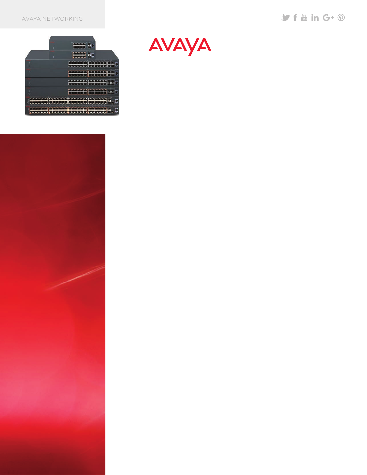
Fig ur e 1: The ERS 35 00 product fa mily
AVAYA ETHER N ET ROUTING
SWITCH 3500 SERIES
HIGHLIGHTS
• Cost effective Fast
Ethernet and Gigabit
Ethernet switches
available in 10, 24 and
48-port model variants.
• Enterprise class features
at SME price points with
100+ enterprise class
features at price points
that fit into tight capital
budgets.
• Fanless models for
silent operation in
open areas – ideal
for classrooms,
boardrooms and retail
shops.
• Resilient stacking that
provides pay as you
grow scaling with up to
80 Gbps of virtual
backplane capacity in a
stack of 8 units.
• PoE/PoE+ models for
powered connection of
IP Phones and other
devices.
• Simplified operations
including 1-minute plug-
and-play capabilities for
IP Phones, automatic
QoS provisioning and
intuitive management
options.
• Unique quick set-up
utility that simplifies
installation with IP
Office.
The Avaya Ethernet Routing Switch (ERS) 3500 is a series of eight high-
performance compact Ethernet switches specifically designed for Mid-
Market, SMEs, branches and open environments outside the wiring closet.
A cost-effective, feature-rich solution, the ERS 3500 Series provides both
standalone and stackable Ethernet switching perfectly suited to the unique
requirements of Mid-Market and SME customers, as well as enterprise
branch offices.
The Avaya Ethernet Routing Switch
3500 is a reliable, low-cost solution that
provides converged services within
single or multiple sites typically of 300
users or less.
It offers three models which can operate
in fanless mode to provide silent
operation for classrooms, hospitality
suites, retail sites or other noise sensitive
environments – outside of the wiring
closet.
It also supports IEEE 802 .3at Power-
over- Ethernet Plus (PoE+) which can
power IP Phones, Wireless Access
Points, surveillance cameras and other
devices. PoE+ with its 32-watt power
budget ensures investment protection
for current as well as future high-
powered end-points.
For environments that need upside
capacity, all ERS 3500 24-port and
48-port models support Avaya’s
Stackable Chassis architecture. This
allows up to eight ERS 3500 units to be
cabled together to form a single logical
chassis with up to 384 user ports and 80
Gigabits of virtual backplane capacity.
The ERS 3500 Stackable Chassis
architecture can also improve network
availability and resiliency through hot-
swap and link aggregation capabilities
across the system.
Delivering high performance Layer 2
switching, Layer 3 local and static
routing, advanced convergence and a
range of security features, the ERS 3500
provides enterprise class features at an
SME price. It also can automate many of
today’s manual processes to simplify
operations and reduce costs for the cost
conscious enterprise.
avaya.com | 1
Page 2
Simplified Operations
The ERS 3500 is well suited for
smaller environments where there
might be little or no local IT staff. It is
designed to be simple to install,
manage and operate. And when
deployed in conjunction with an
Avaya IP Office system the ERS 3500
offers increased operational
simplicity over third party switching
solutions through features that both
simplify the initial deployment as well
as ongoing adds, moves and changes.
entire set up process on the ERS
3500 switch by utilizing LLDP or
ADAC functionality to automatically
set up voice and data VLANs, QoS
and policies on the IP Phones,
meaning that IP Office and IP Phones
Automated switch set up with
Avaya IP Office
For deployment scenarios where
there may not be a data networking
support specialist on site, the ERS
3500 provides an automated script to
enable fast, error free installation
are ready to be connected
immediately. This helps ensure fast
setup and error free deployment
according to Avaya best practices
and consistency between different
locations for large rollouts in multiple
Branch Offices.
when deployed with IP Office. An
installation script automates the
The ERS 3500 Series models
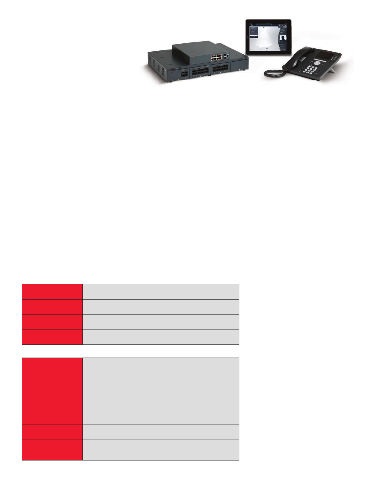
Fig ur e 2: ERS 35 00 with IP Of fi ce , th e Avaya Flare® Co mm un ic ato r for
iP ad D evice and an Avay a 96 0 0 ha nd se t
Validated interoperability with
Avaya IP Office
Avaya has also validated
interoperability between the ERS
3500 and the IP Office system to
ensure the two products work
together seamlessly. This eliminates
any complexities associated with
having to provision, manage and
troubleshoot a third party Switch
with the Avaya voice / unified
communications infrastructure. A
Technical Solutions Guide, available
to partners and end customers,
showcases best practice
configurations, ensuring optimal
performance of the solution.
Fast Ethernet Models
ERS 3526T
ERS 3526T-PWR+
ERS 3550T
ERS 3550T-PWR+
24 x 10/100Mbps + 2 Combo 10/100/1000 or SFP ports + 2
SFP / 2. 5G rear por ts. Fanless .
24 x 10/100Mbps PoE+ ports + 2 Combo 10/100/1000 or SFP
port s + 2 SFP / 2.5G rear ports . Po E budget 370W.
48 x 10/100Mbps ports plus 2 Combo SFP ports (with ports
47-4 8) + 2 SFP / 2. 5G rea r ports .
48 x 10/100 Mbps PoE+ ports plus 2 Comb o SFP por ts (with
47-4 8) + 2 SFP / 2. 5G rea r ports . PoE bud get 370W.
Gigabit Ethernet Models
ERS 3510GT
ERS 3510GT-PWR+
ERS 3524GT
ERS 3524GT-PWR+
ERS 35 49 GT S
ERS 3549GTS-PWR+
2 | avaya.com
8 x 10/ 100/10 00M bps + 2 SFP por ts. Standal on e and Fanles s.
8 x 10/100/1000Mbps PoE+ ports + 2 SFP ports. Standalone.
Fanless mode @ 60W PoE budget, Fan operation mode @
170W PoE budget.
24 x 10/100/1000Mbps with 4 Combo SFP ports (with ports
21-24) + 2 SFP / 2. 5G rea r ports
24 x 10/100/1000Mbps PoE+ ports with 4 Combo SFP ports
(with ports 21-24) + 2 SFP / 2.5G rear ports. PoE budget
370W.
48 x 10/100/1000 ports, plus 2 Combo SFP ports (with ports
47-48), plus 1 SFP+ uplink port, plus 2 SFP / 2.5G rear ports.
48 x 10/100/1000 PoE+ ports, plus 2 Combo SFP ports (with
ports 47-48), plus 1 SFP+ uplink port, plus 2 SFP / 2.5G rear
ports.
Certified 1-minute plug-andplay for IP Phones
Plug-and-play means that as soon as
an IP Phone is plugged into an Avaya
Ethernet Switch, the IP Phone is
automatically recognized and
configured. This feature can
dramatically simplify the roll out of IP
Phones and simplify ongoing adds,
moves and changes; empowering
employees to move their own phones
without the assistance of an outside
contractor. To enable this plug-and-
play capability, Avaya offers IEEE
802.1AB Link Layer Discovery
Protocol and LLDP-Media Endpoint
Discovery (LLDP-MED) as well as the
Avaya Auto Discovery and Auto
Configuration (ADAC) feature.
Page 3

With LLDP enabled, the ERS 3500
learns the identification of
neighboring devices and provides
these details to the network
management system. This enables the
system to have the most up-to-date
physical view of the network. In
addition, ERS 3500 can dynamically
apply voice VLANs and QoS to both
the IP Phone and the attached Edge
Switch port. When the IP Phone is
moved to another location, the
configuration is automatically
updated. QoS is also automatically
provisioned on the ERS 3500 uplink
ensuring voice is given top priority
into the Core. With one of the most
comprehensive implementations of
LLDP in the industry, Avaya offers
enhancements for standards based
provisioning of Avaya IP Phones via
integrated and customizable TLV
support.
and requires little to no formal
training for individuals with
networking backgrounds.
• For customers who are looking for a
simple Graphical User Interface
(GUI) for management and
provisioning, Avaya’s Enterprise
Device Manager (EDM) is an
embedded web-based element
management and configuration tool
that enables set-up, configuration
and monitoring of a single device
using either HTTP or HTTPS (Secure
Web). The on-box embedded
version of EDM is available at no
extra charge with every switch and
can be accessed by a standard web
browser. There is also an off-box
version available as a free
downloadable software plug-in that
can be installed on Avaya’s
Configuration and Orchestration
Manager (COM) application.
The Avaya ERS 3500 supports secure
management via IPv4 or IPv6 through
features such as Secure Shell
(SSHv1/2), Secure Sockets Layer
(SSL), Simple Network Management
Protocol (SNMPv1,2,3), IP Manager
Lists, and administrative
authentication via RADIUS or
TACACS+ when connecting to the
switch or stack.
Convergence-ready
for Unified
Communications,
High-Definition Video
and more
For businesses looking to consolidate
all forms of communication – voice,
video and data – on a single
infrastructure, the Avaya ERS 3500
Series delivers functionality that
simplifies convergence of these
technologies.
These features not only save network
operators time, they can virtually
eliminate the likelihood of a
provisioning error during a large IP
Phone deployment. Third-party
testing conducted by Miercom1
validated that when IP Phones were
plugged into an Avaya Ethernet
Switch, they were operational in just
over 1 minute.
Intuitive Management
ERS 3500 Series offers flexible
options for managing,
troubleshooting and operating your
devices.
• For customers more comfortable
using the Command Line Interface
(CLI), the ERS 3500 offers an
industry-aligned CLI that is intuitive
• For customers rolling out many ERS
3500 devices, the Avaya
Configuration and Orchestration
Manager (COM) application,
simplifies multi-element
configuration via wizards and
templates – increasing consistency
and reducing the chances of error
during configuration changes. COM
also provides network discovery,
device backup, bulk configuration
management and audits of
configuration changes.
• SNMP-based management (SNMP
v1, v2 and v3) provides an
alternative standards-based
management approach as well as an
interface for Configuration and
Orchestration Manager.
Support for IEEE 802.3at PoE+
to power your Converged
Device
Through support for IEEE 802.3at
PoE+ which delivers up to 32 Watts of
power per port to end-devices, ERS
3500s are able to power IP Phones,
Wireless LAN Access Points,
networked high-definition CCTV
cameras and other devices. This
eliminates the need for separate
power supplies for each unit, enabling
reduced cabling and management
costs for adds, moves, or changes.
The higher power budget delivered
by the PoE+ standard ensures that
customers have the added flexibility
of converging video surveillance
traffic over the network, since pan, tilt
avaya.com | 3
Page 4
and zoom cameras are one of the end
devices that require the additional
power provided by PoE+. It also
ensures investment protection for
future end points, such as new
Wireless LAN Access Points (3x3
802.11n Access Points and emerging
802.11ac Access Points) as well as
next-generation video phones.
The 24-port and 48-port PoE+
enabled products (ERS 3526T-PWR+,
ERS 3550T-PWR+, 3524GT-PWR+
and ERS 3549GTS-PWR+) support a
maximum power budget of 370
Watts. And the 10-port Gigabit
Ethernet model (ERS 3510-PWR+)
supports a maximum power budget
of 170 Watts – dramatically higher
than competitive switches in its
class – enabling it to deliver a
concurrent average of 20 Watts of
power to each of the eight PoE+
enabled access ports.
Comprehensive QoS
capabilities
The ERS 3500 series delivers
unsurpassed control for networks
supporting a wide range of different
application types. The ERS 3500
classifies, prioritizes and marks LAN
IP traffic using up to four hardware
queues on every port – including the
rear SFP ports.
Classification can be based on MAC
address, IP ToS/DSCP marking, IP
source/destination address or
subnets, TCP/UDP source/destination
port/port range, IEEE 802.1p user
priority bits, ingress source port, IP
Protocol ID (e.g., TCP, UDP, IGMP),
EtherType (e.g., IP, IPX) or the IEEE
802.1Q VLAN ID. Comprehensive
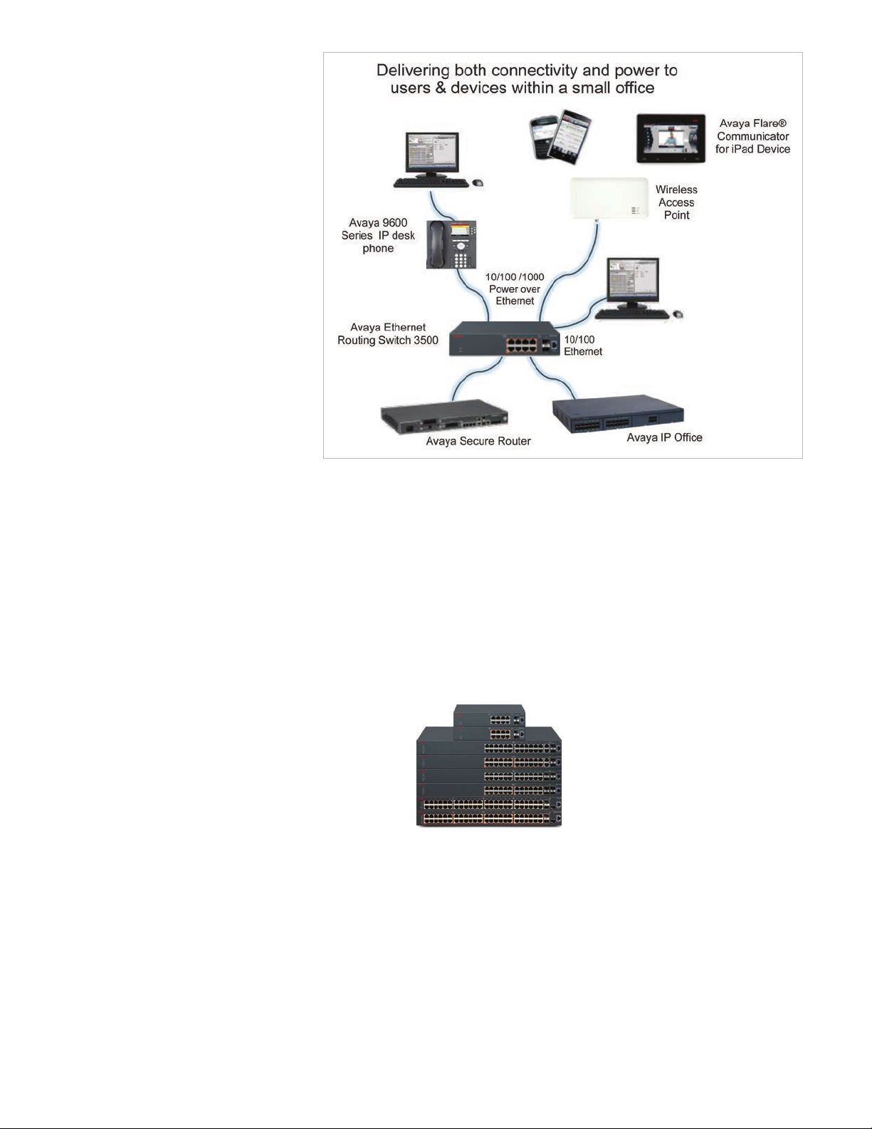
Fig ur e 3: ERS 35 00 deploym ent sc en ario
traffic policing and traffic shaping are
also supported.
Intelligent stacking
solution delivering
scalability, flexibility,
resilience and
performance
No one knows
stacking like
Avaya . We
introduced our
first Stackable
Chassis
product in 1998 and have been
perfecting the technology ever since.
We were the first and only vendor to
break the Terabit boundary with our
ERS 5600 Series products and we
have differentiated ourselves in the
industry by ensuring that our
Stackable Chassis perform like a
traditional modular chassis
implementation. We offer genuine
chassis-like features including true
pay-as-you-grow scaling and in
service maintenance and restoration.
From a management perspective, our
Stackable Chassis looks like a single
network entity – utilizing only a single
IP address.
Up to eight ERS 3500 units can be
stacked – combining 24 or 48-port
models – to deliver up to 80Gbps
stacking throughput and up to 384 x
10/100/1000 user ports. Stacking is
supported on ERS 3526T/3526T-
PWR+, ERS 3550T/3550T-PWR+, ERS
3524GT/3524GT-PWR+ and ERS
3549 GTS/3549 GTS-PWR+ models.
High performance architecture
with true pay-as-you grow
scaling
Our Stackable Chassis products
combine non-blocking internal
switching fabrics with high-speed
virtual backplane architecture for a
4 | avaya.com
Page 5
high performance solution that scales
proportionally as new switches are
added. The ERS 3500 series scales to
a maximum of 80Gbps of virtual
backplane throughput by simply
cabling up 8 units together. Avaya’s
Stackable Chassis architecture
simplifies stack management.
Customers do not have to worry
about different software versions on
different products, since all ERS 3500
units run the same software image.
The software image is loaded onto
the base unit of the stack which then
loads the image to all the other
Switches in the stack. As new units
are added to the stack, the ERS 3500
automates the software image and
configuration download process.
Third party testing1 has validated that
new ERS 3500 units can become
operational in just over 2 minutes of
being cabled into the stack.
To ensure wire-speed performance,
our Stackable Chassis architecture is
based on a shortest-path forwarding
algorithm for optimal data flow
across the stack. Unlike competitive
solutions that use unwieldy
logical ring or token technology,
Avaya allows traffic to flow upstream
and downstream simultaneously from
every Switch connected to the virtual
backplane, optimizing performance,
resiliency, and resource utilization.
Avaya has an additional advantage in
that Quality-of-Service settings are
honored as traffic passes over the
stacking connections – providing
applications with optimal
performance, and a positive user
experience.
All ERS 3500 24 and 48-port models
come with two in-built Stackable
Chassis interfaces for simple, cost-
effective and efficient connectivity.
Unlike comparative offerings which
daisy chain low-speed interfaces,
this design frees uplink ports for
dedicated connectivity to the
backbone. In addition to the stacking
cables, a return cable is also used to
provide full virtual chassis resiliency
and to protect against any stack port,
Switch unit or cable failures.
Unlike competitive solutions which
charge large premiums for stacking,
the ERS 3500 offers the ability for
customers to utilize its Stackable
Chassis architecture without incurring
any licensing or hardware costs.
In-service maintenance and
restoration
Virtual hot swap, a critical
serviceability and operability
capability, helps ensure that failure in
any stacked unit is quickly and easily
rectified. Pioneered in modular
switches, virtual hot swap is available
in Avaya Stackable Chassis solutions
where, without complex engineering,
it enables immediate like-for-like unit
replacement with no impact on other
functionality and traffic, empowering
operators to deploy our solutions just
as they would a chassis. If a failure
occurs, neighboring switches
automatically wrap their fabric
connections to help ensure that other
Switches in the stack are not
impacted. The failed unit is simply
disconnected from the fabric and,
without pre-staging of software or
configuration, a like unit is inserted,
cabled, and powered-up. The
Automatic Unit Replacement (AUR)
process self-manages the software
and configuration downloads to the
new Switch then brings it online,
without the need for an engineer to
manage the process.
Further complementing the Avaya
ERS 3500 solution, Avaya supports
standards-based 802.3ad Link
Aggregation as well as its own Multi-
Link Trunking technology that allows
grouping of ports to form high-speed
trunks/aggregations. These bundles
or groups of ports can be distributed
across different units in the same
stack, delivering higher levels of
resilience in case of link or switch
failure to help ensure that traffic gets
to its destination.
Stack health-check monitoring, a real-
time, at-a-glance view of stack
operational status and health,
further enhances operational and
management simplicity.
Centralized Management
From a management perspective, an
ERS 3500 Stackable Chassis solution
appears as a single networking
entity – utilizing only a single IP
Address. This can significantly reduce
the number of Switches to be
managed within the network as a
stack of up to 8 Switches can be
managed just as easily as a single
device.
avaya.com | 5
Page 6

Increasing access
security at the Edge
The Ethernet Routing Switch 3500
offers a high level of security with
authenticated network access that
leverages IEEE 802.1X Extensible
Authentication Protocol (EAP) with
multiple extensions including support
for Multi-Host Multi-Authentication
mode (MH MA), Multi-Host Single Authentication mode (MHSA),
non EAP device support
(i.e. printers, etc.) and RADIUS
based MAC authentication support.
Up to 32 host devices per switch port
are supported in these modes .
Based on the IEEE 802.1X standard,
EAP limits access to the network
based on user credentials. A user is
required to login to the network using
a username/password; the user
database is maintained on the
authentication server (not the Switch).
Additionally MAC-address based
security limits access to only networkauthorized and trusted personnel,
including full tracking of network
connections. Network access is
granted or denied via proper MACaddress identification (up to a
maximum of 448).
When advanced, policy-based and
centralized user/device authentication
is required, the Avaya ERS 3500 can
be used in conjunction with the
innovative Avaya Identity Engines
portfolio solution. This easy-todeploy, policy-based solution
assigns network access rights and
permissions based on user role, where
the user connects (local or remote)
and how the user connects (wired or
wireless). In this way, each connected
device and user are known and are
governed by device-specific security
policies. For example, based on
their network credentials, an
employee using a corporate
owned device will be granted full
corporate access however, while
using a non-corporate-owned device,
they will be granted limited access.
As the number of employee-owned
devices increases, Identity Engines
can help network operators retain
control by running device health
checks and verifying user and device
credentials. Identity Engines can
enforce network access permission
levels without undue effort on the
part of the IT staff. It can also apply
consistent access and security
policies to all end points – whether
they be wired or wireless.
In addition, the Avaya ERS 3500
offers security features that help
protect against malicious network
attacks. These include increased
protection from snooping of DHCP
services, verification and filtering
of ARP traffic via in-hardware
processing (Dynamic ARP
inspection), restriction of IP traffic to
registered end devices (IP Source
Guard), and control of the flow of
Spanning Tree BPDUs within the
network (BPDU Filtering).
Compact Form Factors
with Flexible
Installation Options
The 10 port ERS 3500 models
(3510GT & 3510GT-PWR+), which are
1U tall, 8.75” wide and 8” and 11” deep
(44.5mm x 220mm x 200mm and
280mm) respectively, can be installed
on a table or shelf using rubber feet
(included), or can be wall mounted
using the wall mount screws and
anchors (also included). Additionally,
optional rack accessory kits are
available allowing the ERS 3510GT
and ERS 3510GT-PWR+ to be
mounted either alone or with two
units side-by-side in a standard
19” rack.
The 24 and 48-port ERS 3500 models
can be installed on a table or shelf or
wall mounted using the included rack
mount brackets mounted at 90
degrees, or in a standard 19”
equipment rack.
Energy Efficiency
New regulations and rising awareness
of the ever-increasing cost of
electrical power keep energy
efficiency top of mind. An innovator
in this area, Avaya has built energy
efficiency into many of its hardware
products. In fact, independent testing
indicates that Avaya LAN Switches,
Call Servers, Gateways, Unified
Messaging Servers and Gigabit IP
Phones are typically more energy
efficient than competitive equipment.
The ERS 3500 is based on highly
efficient power supplies – delivering
over 80% ef ficiency.2 The ERS 350 0
also supports dynamic power
management where each port can
be configured to limit the power
delivered to a device and for power
priority level—low, high, and critical.
The ERS 3500 also supports Avaya
Energy Saver which can further
conserve energy by turning down
port speeds during designated offpeak hours.
Lifetime Warranty
Avaya includes industry-leading
warranty services for our portfolio of
Stackable Chassis Switches, including
Avaya ERS 3500 Series products. The
Lifetime Hardware Warranty Offer
includes complimentary nextbusiness-day shipment of
replacement units for the life of the
product (including fans and power
supplies) and technical support as
follows: Basic technical support for
the supported lifecycle of the product
and full technical support for the first
90 days after purchase. Products sold
on or after July 1, 2015 are supported
by the Lifetime Software Warranty
Offer. This provides our Customers
6 | avaya.com
Page 7

with access to software if and when
published, so that the product’s
conformity to published
specifications and capabilities may be
maintained. For products sold prior to
July 1, 2015, Avaya also offers a very
cost-effective option to purchase the
Software Release Service, providing
access to new feature releases and
Model Specifications
ERS 3526T
additional hardware support
programs. Detailed information on
Avaya’s Lifetime Warranty Offers is
available online.
Summary
Avaya is positioned to provide an
end-to-end solution for converged
networks. The Ethernet Routing
Switch 3500 Series, along with
other Avaya products, can increase
profitability and productivity,
streamline business operations, lower
costs and help your business gain a
competitive edge.
Switch Details:
Dimensions:
Weight:
Power and
Thermal:
ERS 3526T-PWR+
Switch Details:
Dimensions:
Weight:
Power and
Thermal:
24 10/100BASE-TX ports, plus 2 Combo 10/100/1000BASE-T or SFP ports
2 rear SFP ports can be used as additional ports in Standalone Mode, or, 2 rear ports delivering up to 10Gbps
(FDX) of Stackable Chassis throughput per Switch in Stacking Mode
Fanless operation
System CPU spee d: 400M Hz
System memory: 64M B Fl ash, 25 6MB DRAM
RJ-45 Console port provides industry standard serial port connectivity
Switch capacity and forwarding rate (64-byte): 12.8Gbps / 9.5Mpps
MTBF: 645, 5 10 hrs
Height: 1U or 44.5mm / 1.75”
Width: 440mm / 17.5”
Depth: 280mm / 11”
3. 60kg / 8lb
Input volta ge: 100 to 240 VAC@ 47 to 63 HZ
Input current (max): 0.28A@1 00VAC
Power consumptio n: 28.5 Wat ts max
Thermal rating (output): 65 BTU/hr max
24 10/100BASE-TX ports with support for IEEE 802. 3af PoE or IEEE 802.3at PoE+, plus 2 Combo
10/100/1000BASE-T or SFP ports
2 rear SFP ports can be used as additional ports in Standalone Mode, or, 2 rear ports delivering up to 10Gbps
(FDX) of Stackable Chassis throughput per Switch in Stacking Mode
System CPU spee d: 400M Hz
System memory: 64M B Fl ash, 25 6MB DRAM
RJ-45 Console port provides industry standard serial port connectivity
Switch capacity and forwarding rate (64-byte): 12.8Gbps / 9.5Mpps
MTBF: 332,778
Height: 1U or 44.5mm / 1.75”
Width: 440mm / 17.5”
Depth: 280mm / 11”
4.50kg / 10lb
Input volta ge: 100 to 240 VAC@ 47 to 63 HZ
Input current (max): 5.0A@1 00VAC
Power consumptio n: 500Watts ma x
Thermal rating (output): 360 BTU/hr max
Maximum power budget: 370 Watt s
avaya.com | 7
Page 8

Model Specifications
ERS 3550T
Switch Details:
Dimensions:
Weight:
Power and
Thermal:
48 x 10/100 BA SE-TX ports, plus 2 Combo 10/ 100/1 000BAS E-T or SFP port s
2 rear SFP ports can be used as additional ports in Standalone Mode, or 2 rear ports delivering up to 10Gbps
(FDX) of Stackable Chassis throughput per Switch in Stacking Mod e
Sta cking, up to 8 units with 10 Gbps throughput per Switch
System CPU spee d: 400 Mhz
System memory: 32MB Flash, 128M B DRA M
RJ-45 Console port provides industry standard serial port connectivity
Switch capacity and for wa rding rate (64- by te): 17.6G bps / 13 .1Mpps
MTBF: 446,323
Weight: 1U or 445mm / 1.75”
Width: 440 mm / 17.5”
Depth: 280mm / 11”
4.6kg / 10.2lb
Input volta ge: 100 to 240 VAC @ 47 to 63 Hz
Input current (max): 0.8 3 Amps @ 10 0 VAC
Power consumptio n: 35 Watts max
Thermal rating (output): 11 8 BTU/hr max
ERS 3550T-PWR+
Switch Details:
Dimensions:
Weight:
Power and
Thermal:
48 x 10/100BASE-TX ports with support for IEEE 802.3ad PoE or IEEE 802.at PoE+, plus 2 Combo
10/ 100/10 00BAS E-T or SFP ports
2 rear SFP ports can be used as additional ports in Standalone Mode, or 2 rear ports delivering up to 10Gbps
(FDX) of Stackable Chassis throughput per Switch in Stacking Mod e
Sta cking, up to 8 units with 10 Gbps throughput per Switch
System CPU spee d: 400M hz
System memory: 32MB Flash, 128M B DRA M
RJ-45 Console port provides industry standard serial port connectivity
Switch capacity and for wa rding rate (64- by te): 17.6G bps / 13 .1Mpps
MTBF: 237,581
Weight: 1U or 445mm / 1.75”
Width: 440 mm / 17.5”
Depth: 280 mm / 11”
5.6kg / 12.7lb
Input volta ge: 100 to 240 VAC @ 47 to 63 Hz
Input current (max): 6.8 Amps @ 100 VAC
Power consumptio n: 504 Wat ts max
Thermal rating (output): 456 BTU/h r max
8 | avaya.com
Page 9

Model Specifications
ERS 3510GT
Switch Details:
Dimensions:
Weight:
Power and
Thermal:
8 10/ 100/10 00BAS E-T ports with 2 SFP po rts
Fanless operation
Standalone
System CPU spee d: 400M Hz
System memory: 64M B Fl ash, 25 6MB DRAM
RJ-45 Console port provides industry standard serial port connectivity
Switch capacity and forwarding rate (64-byte): 20Gbps / 14.9Mpps
MTBF: 892,667 hrs
Height: 1U 44.5mm / 1.75”
Width: 220mm / 8.75”
Depth: 200mm / 8”
1.75kg / 3.9lb
Input volta ge: 100 to 240 VAC@ 47 to 63 HZ
Input current (max): 0.18A @ 100VAC,
Power consumptio n: 18 Watt s max
Thermal rating (output): 61 BTU/ hr max
ERS 3510GT-PWR+
Switch Details:
Dimensions:
Weight:
Power and
Thermal:
8 10/ 100/10 00BAS E-T ports with suppor t for IEEE 802.3 af PoE or IEEE 802.3 at PoE+ with 2 SFP por ts
Standalone
Dual power modes - fanless operation in Low Power Budget mode @ 60W max PoE budget, or normal fan
operation in High Power Budget mode @ 170W max PoE budget.
System CPU spee d: 400M Hz
System memory: 64M B Fl ash, 25 6MB DRAM
RJ-45 Console port provides industry standard serial port connectivity
Switch capacity and forwarding rate (64-byte): 20Gbps / 14.9Mpps
MTBF: 673 ,452 hrs
Height: 1U 44.5mm / 1.75”
Width: 220mm / 8.75”
Depth: 280 mm / 11”
2.70kg / 6lb
Input volta ge: 100 to 240 VAC@ 47 to 63 HZ
Input current (max): 2.1A @ 100VAC
Power consumptio n: 210 Wat ts
Thermal rating (output): 156 BTU/hr max
Maximum power budget: 170 Watt s
avaya.com | 9
Page 10

Model Specifications
ERS 3524GT
Switch Details:
Dimensions:
Weight:
Power and
Thermal:
ERS 3524GT-PWR+
24 10/1 00/10 00BASE-T por ts, with 4 Combo SFP ports (with port s 21-24)
2 rear SFP ports can be used as additional ports in Standalone Mode, or, 2 rear ports delivering up to 10Gbps
(FDX) of Stackable Chassis throughput per Switch in Stacking Mode
System CPU spee d: 400M Hz
System memory: 64MB Flash, 256MB DRAM
RJ-45 Console port provides industry standard serial port connectivity
Switch capacity and forwarding rate (64-byte): 52Gbps / 38.7Mpps
MTBF: 657,61 9 hrs
Height: 1U 44.5mm / 1.75”
Width: 440 mm / 17.5”
Depth: 280mm / 11”
3. 55kg / 7.8lb
Input volta ge: 100 to 240 VAC@ 47 to 63 HZ
Input current (max): 0.28A @ 100VAC
Power consumptio n: 28.5 Wat ts max
Thermal rating (output): 95 BTU/ hr max
Switch Details:
Dimensions:
Weight:
Power and
Thermal:
24 10/100/1000BASE-T ports with support for IEEE 802.3af PoE or IEEE 802.3at PoE+, with 4 Combo SFP
port s (with ports 21-24)
2 rear SFP ports can be used as additional ports in Standalone Mode, or, as 2 rear HiStack ports delivering
up to 10Gbps (FDX ) of Sta ckab le Chassis throu gh put per Switch in Sta cking Mode
System CPU spee d: 400M Hz
System memory: 64M B Fl ash, 25 6MB DRAM
RJ-45 Console port provides industry standard serial port connectivity
Switch capacity and forwarding rate (64-byte): 52Gbps / 38.7Mpps
MTBF: 336, 357 hrs
Height: 1U or 44.5mm / 1.75”
Width: 440mm / 17.5”
Depth: 280mm / 11”
4.61kg / 10.2lb
Input volta ge: 100 to 240 VAC@ 47 to 63 HZ
Input current (max): 5.0A@1 00VAC
Power consumptio n: 500 Wat ts max
Thermal rating (output): 357 BTU/hr max
Maximum power budget: 370 Watt s
10 | avaya.com
Page 11

Model Specifications
ERS 3549GTS
Switch Details:
Dimensions:
Weight:
Power and
Thermal:
48 10/100/ 1 000 BASE-T ports , with 2 Combo SFP port s (with ports 47-48)
1 SFP+ (1Gig or 10Gig) up link port
2 rear SFP ports can be used as additional ports in Standalone Mode, or, 2 rear ports delivering up to 10Gbps
(FDX) of Stackable Chassis throughput per Switch in Stacking Mod e
System CPU spee d: 400 MHz
System memory: 64M B Fl ash, 25 6MB DRAM
RJ-45 Console port provides industry standard serial port onnectivity
Switch Capacity and for ward in g rate (64-by te): 120G bps/89 .3M pps
MTBF: 471 , 289 hou rs
Height: 1U 44.5mm / 1.75”
Width: 440 mm / 17.5”
Depth: 405mm / 15.75”
6.15kg / 13.55lb
Input volta ge: 100 to 240 VAC@ 50 to 60 HZ
Input current (max): 0.71A @ 100VAC
Power consumptio n: 65 Watts max
Thermal rating (output): 22 3 BTU/hr max
ERS 3549GTS-PWR+
Switch Details:
Dimensions:
Weight:
Power and
Thermal:
48 10/100/1000BASE-T ports with support for IEEE 802.3af PoE or IEEE 802.3at PoE+, with 2 Combo SFP
port s (with ports 47-48)
1 SFP+ (1Gig or 10Gig) up link port
2 rear SFP ports can be used as additional ports in Standalone Mode, or, 2 rear HiStack ports delivering up to
10Gbps (FDX) of Stackable Chassis throughput per Switch in Stacking Mod e
System CPU spee d: 400 MHz
System memory: 64M B Fl ash, 25 6MB DRAM
RJ-45 Console port provides industry standard serial port onnectivity
Switch Capacity and for ward in g rate (64-by te): 120G bps/89 .3M pps
MTBF: 259,61 5 hours
Height: 1U 44.5mm / 1.75”
Width: 440 mm / 17.5”
Depth: 405mm / 15.75”
6.15kg / 13.55lb
Input volta ge: 100 to 240 VAC@ 47 to 63 HZ
Input current (max): 5.0A @ 100VAC
Power consumptio n: 48 4 Watts max
Thermal rating (output): 424 BTU/hr max
Maximum power budget: 370 watts
avaya.com | 11
Page 12

Avaya Ethernet Routing Switch 3500 Series Ordering Information
ERS 3500 SERIES MODELS
AL3500?01-E6*
AL3500?11- E6*
AL3500?02-E6*
AL3500?12-E6*
AL3500?04-E6*
AL3500?14- E6*
AL3500?05- E6*
AL3500?15-E6*
AL3500?06-E6
Notes:
- Each switch ships with Base software license.
- Stacking cables are not included and must be ordered separately for ERS 3500 24-port and 48-port models.
- The seventh character (?) of the ord er number must be replaced with the prope r letter to indicate desire d prod uct nationalization.
ERS 3526T featuring 24 x 10/10 0 ports , pl us 2 Combo 10/10 0/ 100 0/SFP ports, plu s 2 SFP / 2.5G rear por ts.
Fanless.
ERS 3526T-PWR+ featuring 24 x 10/100 PoE+ ports, plus 2 Combo 10/100/1000/SFP ports,plus 2 SFP /
2. 5G rear por ts. PoE budget 370W.
ERS 3550T featuring 48 x 10/ 100 ports, plus 2 Combo 10/ 100/1 000/SFP ports, plus 2 SFP / 2.5 G re ar
ports. Fanless.
ERS 3550T-PWR+ featu ri ng 48 x 10/100 PoE+ ports, plus 2 Com bo 10/ 1 00/10 00/SFP por ts, plu s 2 SFP /
2. 5G rear por ts. PoE budget 370W.
ERS 3510GT featuring 8 x 10/100/ 1000 por ts, plus 2 SFP por ts. Stand alone. Fanle ss .
ERS 3510GT-PWR+ featuring 8 x 10/100/1000 PoE+ ports, plus 2 SFP ports. Standalone. Fanless mode @
60W PoE budget, Fan ope ration mod e @ 170W Po E budget.
ERS 3524GT featuring 24 x 10/ 100/1000M bps port s, plu s 4 Combo SFP ports (with port s 21-24) + 2 SFP / 2. 5G
rear ports.
ERS 3524GT-PWR+ featuring 24 x 10/100/1000 PoE+ ports, plus 4 Combo SFP ports (with ports 21-24),
plus 2 SFP / 2.5G rear po rts . PoE budget 370W.
ERS 35 49 GT S fe aturing 48 x 10/ 1 00/10 00 ports, pl us 2 Combo SFP po rts (with por ts 47-4 8), plus 1 SFP +
uplink port, plus 2 SFP / 2.5G rear ports.
ERS 3500 SERIES STACKING CABLES
AL3518001-E6
AL3518002-E6
AL3518003-E6
ERS 3500 46cm SFP direct connect stack cable
ERS 3500 1. 5 mete r SFP dire ct connec t stack cable
ERS 3500 3 meter SFP direct connect stack cable
ERS 3500 SERIES ACCESSORIES
AL3511001-E6
AL3511002-E6
AL3511003-E6
Sta ndard set of 19” rack mou nt bra ckets - spare
Optional accessory kit for joining two ERS 3510GT / ERS 3510GT-PWR+ switches together (side-by-side) to
mount in a 19” rack
Optio nal acce ss or y kit for mounting one ERS 35 10GT or ERS 3510 GT-PWR+ switch in a 19 ” rack.
12 | avaya.com
Page 13

Technical Specifications
Avaya Ethernet Routing Switch 3500 Standards Compliance
IEEE 802 .1 D Spanning Tree Protocol
IEEE 802 .1w Rapid Sp anning Tree
IEEE 802 .1 s Multip le Spanning Tree
IEEE 802.1p Prioritizing
IEEE 802 .1 t 802.1D Ma intenance
IEEE 802 .1v VL AN Classification by Protocol and Port
IEEE 802 .1 Q VLA N Tagging
IEEE 802 .1 AB Lin k Layer Discovery Protocol
IEEE 802.1X Ethernet Authentication Protocol
IEEE 802.3 Ethernet
IEEE 802.3af Power over Ethernet
IEEE 802.3at Power over Ethernet Plus
IEEE 802.3ab Gigabit Ethernet over Copper
IEEE 802 .3a d Link Agg regation Control Protocol (LAC P)
IEEE 802.3ae 10Gbps Ethernet
IEEE 802.3i 10Base-T
IEEE 802 .3u Fast Etherne t
IEEE 802 .3x Flow Control
IEEE 802 .3z Gigabit Ethernet
RFC 768 UDP
RFC 783 TF TP
RFC 792 ICMP
RFC 793 TCP
RFC 826 ARP
RFC 85 4 Telnet
RFC 894 IP over Etherne t
RFC 903 Reverse ARP
RFC 950 / RFC 791 IP
RFC 1112 IGMP v1
RFC 1122 Requirements for Internet hosts
RFC 1155 SMI
RFC 1156 MIB for manage ment of TCP/IP
RFC 1157 SNMP
RFC 1212 Concise MIB definitio ns
RFC 1213 MIB -II
RFC 1215 SNMP Traps Definition
RFC 1340 Assig ned Numbe rs
RFC 1350 TFT P
RFC 1354 IP Forwardi ng Table MIB
RFC 1398 Ethernet MIB
RFC 1442 SMI for SNMP v2
RFC 1450 MIB for SNMP v2
RFC 1493 Bridge MIB
RFC 1519 Classless Inter- Domain Routing (CIDR)
RFC 15 42 BootP
RFC 1591 DNS Client
RFC 1650 Definitions of Managed Objects for Ethernet-like
Interfaces
RFC 19 08 Coexisten ce bet ween SNMP v1 & v2
RFC 1945 HTTP v1 .0
RFC 19 81 Path MT U Discove ry for IP v6
RFC 2011 SNM P v2 MI B for IP
RFC 2012 SNM P v2 MIB for TD P
RFC 2013 SNM P v2 MIB for UD P
RFC 2096 IP Forwarding Table MI B
RFC 2131 Dyn amic Host Configuration Protocol (DHCP)
RFC 2132 DHC P Option 6, 43 & 60
RFC 2138 RADI US Authe ntication
RFC 2139 RADIUS Accounting
RFC 2236 IGMP v2
RFC 245 4 IPv 6 UDP MIB
RFC 246 0 IPv 6 Specification
RFC 246 4 Transmission of IPv6 packets over Ethe rn et
RFC 2474 Differentiated Services (DiffServ)
RFC 25 41 Secure Shell proto co l architecture
RFC 2597 Assure d Fo rwarding PHB Grou p
RFC 2598 Expedited For ward in g PHB Group
RFC 2616 HTTP 1.1
RFC 2660 HTTPS - Se cure Web
RFC 2665 / RFC 1643 Ethernet MI B
RFC 2674 Q-BR IDG E- MIB
RFC 2819 RMON
RFC 2851 Textual Convention s for Internet network addresses
RFC 2863 Inter faces Group MIB
RFC 2865 RADI US
RFC 2866 RADIUS Accounting
RFC 2869 RADI US Ex tensions - Interim update s
RFC 2933 IGM P MIB
RFC 3046 DHCP Relay Ag ent In form ation Option 82
RFC 3058 RADI US Authe ntic ation
RFC 3140 Per- Hop Beh avior Identification codes
RFC 31 62 IPv6 RADI US Client
RFC 324 6 Expedite d Fo rwardi ng Per-Hop Behavior
RFC 3260 Architec tu re for Dif fere ntiated Services
RFC 3361 DHCP Option 120 for SI P Servers
RFC 3289 Dif fSe rv MI Bs
RFC 3410 SNMPv3
RFC 3411 SNM P Fram eworks
RFC 3412 SNMP Message Processing
RFC 3413 SNM Pv3 Applications
RFC 3414 SNM Pv3 US M
RFC 3415 SNMP v3 VACM
RFC 3416 SNMP
RFC 3417 SNM P Transport Mappings
RFC 3418 SNMP v2 MIB
RFC 34 84 Defa ult Address Sele ctio n fo r IPv 6
RFC 3513 IPv6 Addressing Arc hitecture
RFC 3579 RAD IUS suppo rt for EA P
RFC 3584 Co-existence of SNMP v1/v2/v3
RFC 3587 IPv6 Globa l Unicast Format
RFC 3596 DNS exten sion s to support IP v6
RFC 3621 Power ove r Ethernet MIB
RFC 3635 Definitions of Managed Objects for the Ethernet-like
Interface Types
RFC 3826 AES for the SNMP User-based Security Model
RFC 3879 Deprecating Site Local Addresses
RFC 3993 DHC P Subscriber-ID sub-option
RFC 4007 Scoped Address Architecture
RFC 4022 TCP MIB
RFC 4113 UDP MIB
RFC 4133 Entity MIB
RFC 4193 Unique Local IP v6 Unic as t Addresses
RFC 4250 SSH Protocol Assig ned Numbe rs
RFC 4251 SSH Protocol Architecture
RFC 4252 SSH Auth entication Protocol
RFC 4253 SSH Transport Layer Protocol
RFC 4254 SSH Connec tion Protocol
RFC 429 1 IPv 6 Addressing Architec ture
RFC 4293 IP v6 MI B
RFC 4301 Security Archite cture fo r the Internet Protocol
RFC 4344 SSH Tran sport laye r En cr yption Modes
RFC 4345 Imp roved Arc fo ur Modes for SS H
RFC 4432 SSHv2 RSA
RFC 44 43 ICMPv 6 for IPv6
RFC 4541 Considerations for IGMP and MLD sn oo ping switches
RFC 4604 IGMP v3
RFC 4673 RADIUS Dyn amic Authorizatio n Ser ver MI B
RFC 4675 R AD IUS Attributes for VLAN and Priorit y Support
RFC 471 6 SSH Public Key File Format
RFC 4789 SN MP over IE EE 802 Networks
RFC 48 61 Neighb or Discovery for IPv6
RFC 48 62 IPv6 Stateless Address Au to-Configuration
RFC 5010 DHCP v4 Relay Agent Flags Suboption
RFC 5095 Deprecation of Type 0 Routing Headers in IPv6
RFC 5176 Dyna mi c Authorization Extensions to RADI US
RFC 58 59 TFTP Ser ver DHCP Option
avaya.com | 13
Page 14

About Avaya
Avaya is a leading,
global provider of
customer and team
engagement solutions
and services available
in a variety of flexible
on-premise and cloud
deployment options.
Avaya’s fabricbased networking
solutions help simplify
and accelerate the
deployment of business
critical applications
and services. For more
information, please visit
www.avaya.com.
General Performance
Switch Fabric performance: 12.8Gbps to
120Gbps
Frame for wa rding rate: 9.5 to 89. 3Mp ps
Latency (64 byte packet LIFO): 2.4 to 3.6
microseconds (all GbE ports) and 7.9
microsecond s (FE access por ts)
Frame len gth: 152 2 by tes (including Q tag)
Jumbo Frame suppor t: up to 9216 octets
MLT / 802.3ad LACP: 6 groups with 4 active
trunks
Concurrently configured VLAN s: 256
Egress queues: 4
Multi ple Spanning Tree Gro ups: 8
MAC Address: up to 16,000
DHCP Snooping: up to 512 entries
802.1X Clients per port: 32
ARP Entri es : up to 512
IP Inte rfaces: up to 32
RMON entries per port: 4 groups
ADAC (IP Pho nes): 32 per po rt
QoS filte rs per precedence: 25 6
QoS precedence: 4
QoS filte rs per switch: 1024
Pluggable Interfaces
100BASE-FX SFP up to 2km reach over MMF
(Duplex LC)
1000BASE-T SFP up to 100m over CAT5E or
bette r UTP Cab le (RJ -45)
1000BASE-SX SFP up to 550m reach on
MM F (D uplex LC)
1000BASE-LX SFP up to 550m reach on
MM F, and up to 10 km on SMF (Duplex LC)
1000BASE-XD CDWM SFP up to 40 km
rea ch on SMF (Duplex LC)
1000BASE-ZX CDWM SFP up to 70 km reach
on SMF (Duplex LC)
1000BASE-EX SFP up to 120 km reach on
SMF (D uplex LC)
1000BASE-BX SFP up to 10 and 40 km reach
varia nt s on SM F (LC)
10GBASE-SR SFP+ up to 300m reach over
MM F (D uplex LC)
10GBASE-LRM SFP+ up to 220 m ove r FD DIgrade MM F (Duplex LC)
10GBASE-LR SFP+ up to 10km reach over
SMF (D uplex LC)
10GBASE-ER SFP+ up to 40km reach over
SMF (D uplex LC)
10GBASE-X SFP+ Direct Attach Cables, in 3,
5, & 10m lengths
Environmental
Specifications
• Operating temperature: 32° and 122° F
(0° and 50° C)
• Operating altitude: 10,000 ft.
• Storage temperature: -40C to 70C
• Storage altitude: 10,000 ft
• Acoustic noise (dB): up to 58
(0 for Fan less models)
• Operating humidity: 95% RH noncondensing
• Storage humidity: 95% RH non-condensing
• No nearby heat sources such as hot air
vents or direct sunlight
• No nearby sources of severe
electromagnetic noise
• No excessive dust
• Adequate power source within six feet;
on e 15-Amp circuit req ui red for ea ch
power supply.
• At least 5cm (2”) on each side of the switch
unit for ventilation
Safety Agency Approvals
• IEC 60950 International CB Certification
• EN 60950 European Certification
• UL60950 US certification
• CSA22.2, #60950 Canadian Certification
• NOM Mexican Certification
Electromagnetic
Emissions and Immunity
• CISPR22, Class A/CISPR24 International
• EN55022, Class A/EN55024 European
• FCC , Part 15, Class A US Certification
• ICES- 003, Class A Canadian Certification
• AN/NZS 3548 Australian/NZ Certification
• BSMI - Taiwan - CNS 13438, Class A
• MIC - Korea - MIC, No. 2001-116
• VCCI Class A Japanese Certification
1
Miercom Lab Testing Summary Report “Plug
and Play” Switch es Aug . 2011.
2
Based on Avaya testing
avaya.com | 14
© 2016 Avaya Inc. All Rights Re serve d.
Avaya and the Avaya logo are trademarks of Avaya Inc . and are regis tered in the
United St ates and other countr ies. All other trad emarks identified by ®, TM, or SM
are regis tered ma rks, tra dema rks, an d service marks, respe ctivel y, of Avaya Inc.
Oth er tra de ma rk s ar e th e pro pe r ty o f the ir res pe ct ive own er s.
08 /1 6 • LB 702 8-10
Provide fe edba ck
for thi s do cu me nt
 Loading...