

Page 1

DMC DECT Fundamentals
A
vaya Communications Server 1000
NN43120-114, 02.07
Release 7.5
August 2012
Page 2

©
Avaya Inc.
2012
All Rights Reserved.
Notice
While reasonable efforts have been made to ensure that the
information in this document is complete and accurate at the time of
printing, Avaya assumes no liability for any errors. Avaya reserves the
right to make changes and corrections to the information in this
document without the obligation to notify any person or organization of
such changes.
Documentation disclaimer
“Documentation” means information published by Avaya in varying
mediums which may include product information, operating instructions
and performance specifications that Avaya generally makes available
to users of its products. Documentation does not include marketing
materials. Avaya shall not be responsible for any modifications,
additions, or deletions to the original published version of
documentation unless such modifications, additions, or deletions were
performed by Avaya. End User agrees to indemnify and hold harmless
Avaya, Avaya's agents, servants and employees against all claims,
lawsuits, demands and judgments arising out of, or in connection with,
subsequent modifications, additions or deletions to this documentation,
to the extent made by End User.
Link disclaimer
Avaya is not responsible for the contents or reliability of any linked Web
sites referenced within this site or documentation provided by Avaya.
Avaya is not responsible for the accuracy of any information, statement
or content provided on these sites and does not necessarily endorse
the products, services, or information described or offered within them.
Avaya does not guarantee that these links will work all the time and has
no control over the availability of the linked pages.
Warranty
Avaya provides a limited warranty on its Hardware and Software
(“Product(s)”). Refer to your sales agreement to establish the terms of
the limited warranty. In addition, Avaya’s standard warranty language,
as well as information regarding support for this Product while under
warranty is available to Avaya customers and other parties through the
Avaya Support Web site:
you acquired the Product(s) from an authorized
of the United States and Canada, the warranty is provided to you by
said Avaya reseller and not by Avaya.
Licenses
THE SOFTWARE LICENSE TERMS AVAILABLE ON THE AVAYA
WEBSITE,
APPLICABLE
INSTALLS AVAYA SOFTWARE, PURCHASED FROM AVAYA INC.,
ANY AVAYA AFFILIATE, OR AN AUTHORIZED AVAYA RESELLER
(AS APPLICABLE) UNDER A COMMERCIAL AGREEMENT WITH
AVAYA OR AN AUTHORIZED AVAYA RESELLER. UNLESS
OTHERWISE AGREED TO BY AVAYA IN WRITING, AVAYA DOES
NOT EXTEND THIS LICENSE IF THE SOFTWARE WAS OBTAINED
FROM ANYONE OTHER THAN A V A Y A, AN A V A Y A AFFILIA TE OR AN
AVAYA AUTHORIZED RESELLER; AVAYA RESERVES THE RIGHT
TO TAKE LEGAL ACTION AGAINST YOU AND ANYONE ELSE
USING OR SELLING THE SOFTWARE WITHOUT A LICENSE. BY
INSTALLING, DOWNLOADING OR USING THE SOFTWARE, OR
AUTHORIZING OTHERS TO DO SO, YOU, ON BEHALF OF
YOURSELF AND THE ENTITY FOR WHOM YOU ARE INSTALLING,
DOWNLOADING OR USING THE SOFTWARE (HEREINAFTER
REFERRED TO INTERCHANGEABL Y AS “YOU” AND “END USER”),
AGREE TO THESE TERMS AND CONDITIONS AND CREATE A
BINDING CONTRACT BETWEEN YOU AND AVAYA INC. OR THE
APPLICABLE AVAYA AFFILIATE (“AVAYA”).
HTTP://SUPPORT.AVAYA.COM/LICENSEINFO/ ARE
TO ANYONE WHO DOWNLOADS, USES AND/OR
http://support.avaya.com. Please note that if
Avaya reseller outside
Copyright
Except where expressly stated otherwise, no use should be made of
materials on this site, the Documentation, Software, or Hardware
provided by
Product provided by Avaya including the selection, arrangement and
design of the content is owned either by Avaya or its licensors and is
protected by copyright and other intellectual property laws including the
sui generis rights relating to the protection of databases. You may not
modify, copy, reproduce, republish, upload, post, transmit or distribute
in any way any content, in whole or in part, including any code and
software unless expressly authorized by Avaya. Unauthorized
reproduction, transmission, dissemination, storage, and or use without
the express written consent of Avaya can be a criminal, as well as a
civil offense under the applicable law.
Third-party components
Certain software programs or portions thereof included in the Product
may contain software distributed under third party agreements (“Third
Party Components”), which may contain terms that expand or limit
rights to use certain portions of the Product (“Third Party Terms”).
Information regarding distributed Linux OS source code (for those
Products that have distributed the Linux OS source code), and
identifying the copyright holders of the Third Party Components and the
Third Party Terms that apply to them is available on the A vaya Support
Web site:
Preventing T
“T oll fraud” is the unauthorized use of your telecommunications system
by an unauthorized party (for example, a person who is not a corporate
employee, agent, subcontractor, or is not working on your company's
behalf). Be aware that there can be a risk of Toll Fraud associated with
your system and that, if Toll Fraud occurs, it can result in substantial
additional charges for your telecommunications services.
Avaya Toll Fraud Intervention
If you suspect that you are being victimized by T oll Fraud and you need
technical assistance or support, call Technical Service Center Toll
Fraud Intervention Hotline at +1-800-643-2353 for the United States
and Canada. For additional support telephone numbers, see the Avaya
Support Web site:
vulnerabilities with
sending mail to: securityalerts@avaya.com.
Trademarks
The trademarks, logos and service marks (“Marks”) displayed in this
site, the Documentation and Product(s) provided by Avaya are the
registered or unregistered Marks of Avaya, its affiliates, or other third
parties. Users are not permitted to use such Marks without prior written
consent from Avaya or such third party which may own the Mark.
Nothing contained in this site, the Documentation and Product(s)
should be construed as granting, by implication, estoppel, or otherwise,
any license or right in and to the Marks without the express written
permission of Avaya or the applicable third party.
Avaya is a registered trademark of Avaya Inc.
All non-Avaya trademarks are the property of their respective owners,
and “Linux” is a registered trademark of Linus Torvalds.
Downloading Documentation
For the most current versions of Documentation, see the Avaya
Support Web site:
Contact
See the Avaya Support W eb site:
notices and articles, or to report a problem with your Avaya product.
For a list of support telephone numbers and contact addresses, go to
the Avaya Support Web site:
bottom of the page, and select Contact
Avaya. All content on this site, the documentation and the
http://support.avaya.com/Copyright.
oll Fraud
http://support.avaya.com. Suspected security
Avaya products should be reported to Avaya by
http://support.avaya.com.
Avaya Support
http://support.avaya.com
http://support.avaya.com, scroll to the
Avaya Support.
for product
2 DMC DECT Fundamentals August 2012
Comments? infodev@avaya.com
Page 3

Contents
Chapter 1: New in this release...........................................................................................
Revision History........................................................................................................................................
Chapter 2: Product description.........................................................................................
Contents....................................................................................................................................................
Overview...................................................................................................................................................
Clock requirements..........................................................................................................................
CS 1000E.........................................................................................................................................
Synchronization port.........................................................................................................................
Mobility card (DMC8)................................................................................................................................
DMC8 options...................................................................................................................................
DMC8 - Expander (DMC8-E)...........................................................................................................
Faceplate features............................................................................................................................
DMC Faceplate cables.....................................................................................................................
IPE Shelves Faceplate Cabling........................................................................................................
Inter-shelf faceplate connections......................................................................................................
MG1000E Chassis faceplate cabling...............................................................................................
Basestations..............................................................................................................................................
Basestation housing.........................................................................................................................
Basestation cell................................................................................................................................
DECT handset subscription and de-subscription......................................................................................
DMC DECT Manager................................................................................................................................
DECT Application features...............................................................................................................
Common Services............................................................................................................................
Remote Access Service (RAS)........................................................................................................
Multi-site Mobility Networking subscriptions..............................................................................................
Multi-site Mobility Networking....................................................................................................................
Operating parameters......................................................................................................................
Call forward from a MADN handset..................................................................................................
Card audit.........................................................................................................................................
Network Message Service................................................................................................................
Feature packaging............................................................................................................................
Messaging and Alarms..............................................................................................................................
Chapter 3: Engineering guidelines....................................................................................
Contents....................................................................................................................................................
System capabilities and limits...................................................................................................................
System concentration traffic......................................................................................................................
Blocking............................................................................................................................................
Traffic definitions..............................................................................................................................
Traffic assumptions used for table calculations................................................................................
System hardware parameters..........................................................................................................
System software parameters............................................................................................................
DMC8 engineering guidelines...................................................................................................................
Netprice Order Tool..........................................................................................................................
DECT on Large Systems..................................................................................................................
11
11
13
13
13
14
14
17
17
18
19
19
21
23
23
25
25
27
27
28
29
29
30
30
32
33
34
34
34
34
34
35
37
37
37
37
37
38
38
39
41
41
43
43
DMC DECT Fundamentals August 2012 3
Page 4

DECT on Cabinet system.................................................................................................................
DECT on Chassis system................................................................................................................
DECT on CS 1000E.........................................................................................................................
Rules with new basestations............................................................................................................
Basestation combinations for handsets on a DMC8.................................................................................
Low traffic for a 0.1 Erlang capacity.................................................................................................
Medium traffic for a 0.15 Erlang capacity.........................................................................................
High traffic for a 0.2 Erlang capacity.................................................................................................
Superloop and IPE shelf calculations...............................................................................................
Chapter 4: Site planning.....................................................................................................
Contents....................................................................................................................................................
Overview...................................................................................................................................................
Site survey................................................................................................................................................
Customer requirements....................................................................................................................
Site survey example.........................................................................................................................
Site planning example: Able-Studio.................................................................................................
Deployment...............................................................................................................................................
Identifying initial critical points on the floor plan...............................................................................
Locating cell centres.........................................................................................................................
Determining cell boundaries.............................................................................................................
Identifying critical points and cell boundaries...................................................................................
Marking the points, centres, and boundaries on the floor plan.........................................................
Deployment illustrations...................................................................................................................
Deployment terms............................................................................................................................
Coverage terms................................................................................................................................
Deployment tool........................................................................................................................................
Preparing the tool for deployment....................................................................................................
How the deployment tool works.......................................................................................................
How to use the deployment tool................................................................................................................
Interpreting handset tones................................................................................................................
Rules for outdoor deployment..........................................................................................................
DECT Deployment Kit 2............................................................................................................................
Deploying DECT.......................................................................................................................................
Correcting problems with audio quality.....................................................................................................
Deploying an external basestation............................................................................................................
Single and multiple floor deployment........................................................................................................
Single-floor deployment....................................................................................................................
Multiple floor deployment.................................................................................................................
Cell re-engineering for high traffic areas...................................................................................................
Traffic volume...................................................................................................................................
About the 12-channel basestation....................................................................................................
The cell re-engineering process................................................................................................................
Estimating traffic within a cell...........................................................................................................
Separating the coverage area and recording the number of offices................................................
Creating an estimate table...............................................................................................................
Calculating the number of users with an office outside the cell who walk into the cell.....................
Calculating the number of users inside the cell with an office..........................................................
44
44
44
44
44
44
45
46
46
49
49
49
50
50
52
53
58
58
59
61
62
63
66
74
75
76
78
85
86
86
87
87
91
94
95
96
97
102
106
106
106
107
107
108
108
109
110
4 DMC DECT Fundamentals August 2012
Page 5

Calculating the number of users without an office............................................................................
Totalling the estimate for users in a cell...........................................................................................
Calculating the data for all remaining cells.......................................................................................
Creating a table to document telephone types in a cell....................................................................
Determining cell re-engineering.......................................................................................................
Cell division requirements in special cases..............................................................................................
No office information.........................................................................................................................
A mix of users with and without wired telephones in a cell..............................................................
High handset density deployment.............................................................................................................
Limiting the anticipated number of handsets....................................................................................
Subdividing a cell.............................................................................................................................
Deployment review....................................................................................................................................
Completing a floor plan....................................................................................................................
Checking system capacity................................................................................................................
Review with the customer................................................................................................................
Record floor plan information...........................................................................................................
Record provisioning record information............................................................................................
Review the work...............................................................................................................................
Chapter 5: Installation and configuration.........................................................................
Contents....................................................................................................................................................
Before you begin.......................................................................................................................................
Unpacking the equipment.........................................................................................................................
Provisioning records..................................................................................................................................
System information record...............................................................................................................
Provisioning information record........................................................................................................
Installation record.............................................................................................................................
TN to DECT TN assignment.............................................................................................................
System programming record............................................................................................................
Handset user information record......................................................................................................
Installing the basestation..........................................................................................................................
Rules and guidelines........................................................................................................................
Compatibility.....................................................................................................................................
C4610E and external antenna..........................................................................................................
Installing C4600, C4610, and C4610E basestations........................................................................
Installing the wiring to the MDF........................................................................................................
Installing the external power supply.................................................................................................
Installing the external housing..........................................................................................................
Attaching the external housing to a wall...........................................................................................
Connecting the external housing wiring to the MDF.........................................................................
Installing the external housing..................................................................................................................
Mounting the cabinet........................................................................................................................
Installing additional IPE shelves or CS 1000E cabinets...........................................................................
Installing additional IPE modules.....................................................................................................
Installing IPE module wiring to the MDF..........................................................................................
Installing CS 1000E cabinet wiring to the MDF................................................................................
Expander installation........................................................................................................................
Installing DMC8 and faceplate cables.......................................................................................................
110
111
112
112
113
114
115
115
117
117
117
119
119
120
121
121
121
122
123
123
123
124
125
125
126
127
127
128
128
128
129
129
129
130
131
135
136
138
140
142
149
152
152
153
157
158
158
DMC DECT Fundamentals August 2012 5
Page 6

Compatibility.....................................................................................................................................
Cross-connecting basestations to the DMC8 positions....................................................................
Cross-connecting basestations to the DMC8 Relay card.................................................................
Installing DMC8 and DMC8-E in an IPE shelf..................................................................................
Installing DMC8 and DMC8-E in an IPE Module Controlled by MGXPEC (CS 1000E)...................
Installing DMC8 and DMC8-E in an Avaya Communication Server 1000E......................................
Chassis installation...........................................................................................................................
Installing faceplate cables and inter-shelf/cabinet cable..................................................................
Installing the DMC DECT application........................................................................................................
Connecting to a DECT system.........................................................................................................
Synchronizing the DECT Application to a DECT system.................................................................
Installing the DME on the DMC8 Relay card....................................................................................
Changing the DMC8 Relay card default IP address.........................................................................
Launching the DECT application..............................................................................................................
Adding DECT............................................................................................................................................
Adding General System Properties..................................................................................................
Setting the DECT system IP address to match the DMC8 Relay card.............................................
Adding the upstream manager IP address, if required.....................................................................
Synchronizing data with DECT.................................................................................................................
Synchronizing DECT PARI and SARI...............................................................................................
Synchronizing DECT parameters.....................................................................................................
Synchronizing DECT Upstream Manager IP address......................................................................
Configuring handsets and retrieve subscription data................................................................................
Retrieving subscription data for handsets........................................................................................
Enabling subscription.......................................................................................................................
Activating the PIN on the handsets..................................................................................................
Handset subscription........................................................................................................................
Basestation Powering and Muting............................................................................................................
Opening RFP window.......................................................................................................................
Setting basestation alarm muting, line power, and comments.........................................................
Upgrade a DECT system to an SNMP-managed system.........................................................................
Configure a local connection............................................................................................................
Dial-up configuration........................................................................................................................
Network and dial-up connections configuration................................................................................
Change the DMC4 relay card default IP address.............................................................................
Reset the DMC4 relay card to the server IP address.......................................................................
Launch the DMC DECT Manager back-end process.......................................................................
DAS configuration............................................................................................................................
Synchronize data with the DECT system.........................................................................................
Activate the firmware on all DMC4 cards.........................................................................................
Implementing and operating MSMN.........................................................................................................
Implementing the MSMN feature......................................................................................................
Operating the MSMN feature...........................................................................................................
Chapter 6: System administration.....................................................................................
Contents....................................................................................................................................................
Logging into the DMC DECT Manager.....................................................................................................
Selecting the PBX that supports DECT....................................................................................................
158
158
160
162
168
170
176
177
179
179
179
183
184
187
188
188
189
190
191
192
193
194
195
195
196
197
197
198
198
199
200
200
201
210
214
214
215
217
221
222
224
224
228
229
229
229
230
6 DMC DECT Fundamentals August 2012
Page 7

DECT Systems window.............................................................................................................................
Opening Subscriptions, Boards, and RFP windows.........................................................................
Connecting to a DECT system.........................................................................................................
Establishing a permanent connection to a DECT system................................................................
Deleting DECT systems............................................................................................................................
Retrieving subscription data for DECT handsets......................................................................................
Enabling subscriptions..............................................................................................................................
Activating the PIN on the DECT handsets................................................................................................
Working with DECT handset subscriptions...............................................................................................
Disabling a DECT handset subscription...........................................................................................
Copying a DECT handset subscription............................................................................................
Moving a DECT handset subscription..............................................................................................
Finding a DECT handset subscription..............................................................................................
Importing a DECT handset subscription...........................................................................................
Exporting a DECT handset subscription..........................................................................................
Force disabling a DECT handset subscription.................................................................................
Deleting TNs that are not on the switch....................................................................................................
Updating data on DMC DECT Manager or updating data on a DECT system.........................................
Provisioning a DECT system remotely......................................................................................................
Remote DMC8 provisioning where the customer site has a DECT manager..................................
Remote DMC8 provisioning where the customer site does not have a DECT manager..................
Subscribing a DECT system remotely......................................................................................................
Remote DECT handset subscription where the customer site has a DECT manager.....................
Remote DECT handset subscription where the customer site does not have a DECT manager....
Modifying system properties.....................................................................................................................
Changing passwords........................................................................................................................
Changing the DECT system name...................................................................................................
Changing the IP address on DMC DECT manager..........................................................................
Changing the IP address on the DECT system DMC8 Relay card..................................................
Changing a PARI or SARI................................................................................................................
Changing the Upstream Manager IP address..................................................................................
Changing the time and date.............................................................................................................
Changing parameters.......................................................................................................................
Keeping or removing non-operational DMC8 cards from DMC DECT Manager......................................
Keeping or removing non-operational basestations from DMC DECT Manager......................................
Resolving a subscription configuration mismatch.....................................................................................
Troubleshooting........................................................................................................................................
Disconnecting...................................................................................................................................
Chapter 7: System maintenance........................................................................................
Contents....................................................................................................................................................
Alarm Code maintenance actions.............................................................................................................
Windows Alarm Snapshot................................................................................................................
LED status for DMC8/DMC8-E and basestation.......................................................................................
Removing and inserting a DMC8 for maintenance...................................................................................
Backing up a DMC8 card configuration and subscription information..............................................
Removing a faulty DMC8 card.........................................................................................................
Inserting a serviceable DMC8 card..................................................................................................
230
230
231
232
233
234
235
236
236
237
238
239
240
241
243
244
245
246
247
248
249
249
250
251
251
252
253
254
255
257
258
259
260
261
262
263
264
264
267
267
268
268
273
275
276
277
278
DMC DECT Fundamentals August 2012 7
Page 8

Restoring subscription data to the serviceable DMC8 card.............................................................
Adding a DMC8 card to a DECT system...................................................................................................
Reusing a DMC8 card in another DECT system..............................................................................
Removing and reinstalling a basestation for maintenance.......................................................................
Muting alarms on a basestation.......................................................................................................
Canceling mute alarms on a basestation.........................................................................................
Disconnecting and reinstalling a basestation...................................................................................
Uploading and activating firmware............................................................................................................
Recovering from a firmware upload failure...............................................................................................
Retrieving current RSSI data....................................................................................................................
RSSI file format................................................................................................................................
Performance Collection.............................................................................................................................
DECT Performance Manager installation.........................................................................................
Set date and time on DMC DECT Manager.....................................................................................
Retrieve upm and epm files..............................................................................................................
Creating a new directory structure...................................................................................................
Rename upm and epm files.............................................................................................................
Creating a database.........................................................................................................................
Using the database..........................................................................................................................
Previously created databases..........................................................................................................
DECT Performance Manager data...................................................................................................
Top-down analysis............................................................................................................................
Setting parameters....................................................................................................................................
Recovering a password.............................................................................................................................
Chapter 8: Changing the DMC8 jumper setting after DECT system upgrade to Release
5.0.........................................................................................................................................
Changing the DMC8 jumper setting..........................................................................................................
Connecting a DECT system to DMC DECT Manager using remote modems and Windows 2000..........
Cable setup......................................................................................................................................
DECT relay board to remote modem...............................................................................................
Configuring NetBEUI Protocol..........................................................................................................
Configuring a dial-up network on the DMC DECT Manager server.................................................
Setting the properties of the new connection...................................................................................
Modem setup....................................................................................................................................
Modem requirements.......................................................................................................................
Setting the modems to factory defaults............................................................................................
Adding a new DECT system to DMC DECT Manager.....................................................................
Changing an existing DECT system on DMC DECT Manager from an Ethernet connection to a
modem connection...........................................................................................................................
Chapter 9: Adding a DMC8 to a non-SNMP DECT system..............................................
Adding a DMC8.........................................................................................................................................
Chapter 10: DMC8 debug port...........................................................................................
Overview...................................................................................................................................................
DMC card.........................................................................................................................................
Items to monitor................................................................................................................................
Monitor port physical connection..............................................................................................................
DMC8 debug port.............................................................................................................................
279
279
281
281
281
282
283
284
286
287
289
289
291
293
294
295
296
298
299
300
301
306
309
310
313
313
315
315
316
317
318
319
320
320
320
321
323
325
325
327
327
327
328
328
328
8 DMC DECT Fundamentals August 2012
Page 9

Connecting a modem.......................................................................................................................
Terminal configuration...............................................................................................................................
Successful connection..............................................................................................................................
Information collection................................................................................................................................
Messages on an idle system.....................................................................................................................
IPC interface.....................................................................................................................................
DS30 interface..................................................................................................................................
Message examples...................................................................................................................................
Chapter 11: Performance Collection file samples............................................................
Equipment Performance Collection file sample........................................................................................
User Performance Collection file sample..................................................................................................
Index.....................................................................................................................................
329
330
330
331
333
333
334
334
337
337
337
339
DMC DECT Fundamentals August 2012 9
Page 10

10 DMC DECT Fundamentals August 2012
Page 11

Chapter 1: New in this release
The following sections detail what is new in DMC DECT Fundamentals, NN43120–1
14 for Release 7.5:
Feature changes
• All DECT Messenger material has been removed. See DECT Messenger Fundamentals
(NN43120-120).
• DSP provisioning information has been added to
Installing DMC8 and DMC8-E in an Avaya Communication Server 1000E on page 170 and now
aligns with the provisioning rules implemented in the ordering tools.
• Configuration information has been added to Installing DMC8 and DMC8-E in an IPE Module
Controlled by MGXPEC (CS 1000E) on page 168 for IPE shelves upgraded to the MG XPEC
controller.
System hardware parameters on page 39 and
Revision History
August 2012 Standard 02.07. This document has been up-issued to update the
compatible operating systems for DMC DECT Manager 2.0.
May 2012 Standard 02.06. This document is up-issued to update location of
DMC slot in Communication Server Release 7.5.
DMC DECT Fundamentals August 2012 11
Page 12

New in this release
12 DMC DECT Fundamentals August 2012
Comments? infodev@avaya.com
Page 13

Chapter 2: Product description
Contents
This section contains information on the following topics:
Overview on page 13
Mobility card (DMC8) on page 17
Basestations on page 25
DECT handsets
DMC DECT Manager on page 29
Multi-site Mobility Networking on page 33
Messaging and Alarms on page 35
Overview
vaya Integrated DECT (DECT) allows users to move freely about their work sites while
A
conducting telephone conversations using wireless handsets. DECT is an acronym for Digital
Enhanced Cordless Telecommunications.
DMC DECT Fundamentals August 2012 13
Page 14

Product description
Figure 1: Main parts of the DECT system
The DECT system is in a CS 1000M IPE shelf or a CS 1000E cabinet or chassis. DECT has
four main components:
a DECT mobility cards
b Basestation
c Handsets
d DMC DECT Manager with DECT application
Clock requirements
The following clock controller cards are mandatory:
NTRB53 Clock Controller card for a CS 1000M SG or MG
•
• NTAK20BD Clock Controller daughterboard or NTAK79AA card with a built-in clock
controller for an Option 11C and CS 1000E Media Gateways
If there is no digital connection to the network, the appropriate clock controller must be installed
and operated in free run mode.
Note:
On EMC-hardened Cabinet systems, the clock controller must be in one of the first three
slots of the CPU cabinet.
CS 1000E
The NTDW63AAE5 Ethernet & Clock Reference Breakout
with MGC and the NTDW67AAE5 MGC DECT clock reference cable, used to synchronize the
14 DMC DECT Fundamentals August 2012
Comments? infodev@avaya.com
Adapter for Option 1 1C cabinet used
Page 15

Overview
backplane clock between two MG1000 chassis, MG 1010 chassis, or Option 1 1C cabinets, are
shown in the figures below.
For CS 1000E DECT installations that span more than 1 cabinet, the NTDW63AAE5 (Option
11C Cabinet Ethernet & Clock Reference Breakout Adapter) is used with the NTDW67AAE5
(Clock Reference Cable) to synchronize the backplane clock between two Option 11C
cabinets. For DECT installations that span more than 1 MG 1000 or MG 1010 main and
expander chassis, the NTDW67AAE5 cable is used to synchronize the backplane clock
between two MG 1000 or MG 1010 chassis. This is in addition to the clock controller
requirement identified above.
DMC DECT Fundamentals August 2012 15
Page 16

Product description
Figure 2: MGC Breakout Adapter for Option 11C
Figure 3: MGC DECT Clock Reference Cable
16 DMC DECT Fundamentals August 2012
Comments? infodev@avaya.com
Page 17

Synchronization port
Figure 4: DECT synchronization
Mobility card (DMC8)
Where multiple DECT
synchronization port must be used. The DECT synchronization port is accessed through a
Main Distribution Frame (MDF) connection. Failure to connect the DECT synchronization ports
of each system can lead to service interruptions.
systems share the same radio coverage area, the DECT
Mobility card (DMC8)
The NTCW00AB DMC8 DECT
and the Meridian 1, or CS 1000M.
Mobility Card provides an interface between the basestations
Figure 5: DECT Mobility Card
The DECT
basestations.
DMC DECT Fundamentals August 2012 17
system supports a mix of DMCs and DMC8s. A DMC8 supports up to eight
Page 18

Product description
All DMC8s support a Point-to-Point Protocol (PPP) connection to the DECT Manager with an
NTCW12DA cable. The DMC8 card requires a NTCW25AA DECT Manager Ethernet (DME)
daughterboard installed to support an Ethernet connection.
Each DMC8 is programmed in the database using LD 10.
The DMC8s are interconnected by faceplate cables, allowing them to pass information to each
other.
DMC8s must be in an IPE shelf or in a cabinet or chassis.
There is no call switching in the DMC8 card. All call switching occurs within the Meridian 1, CS
1000M, or CS 1000E.
DMC8 options
Figure 6: DMC8 options
The component side of the DMC8 contains jumpers J1, J2, and J3. The jumpers indicate card
status.
18 DMC DECT Fundamentals August 2012
Comments? infodev@avaya.com
Page 19

DMC8 - Expander (DMC8-E)
Mobility card (DMC8)
The NTCW01AB DMC8-E DECT
DMC card.
The DMC8-E has additional circuitry required to regenerate faceplate cable signals when a
system contains more than eight DMC8s. The DMC8-E connects two shelves or cabinets in a
DECT system.
Figure 7: DECT Mobility Card - Expander
Mobility Card – Expander provides the same functions as a
If the DMC8-E is used in an IPE module, it must be located in card slot 8. Do not install a DMC8
in slot 8 of an IPE module.
If the DMC8-E is used in a CS 1000E cabinet or chassis, it must be located in card slot 8. Do
not install a DMC8 in slot 8 of a CS 1000E cabinet or chassis.
An NTCW25AA
access. The daughterboard is also required to enable DECT Messaging. The DME
daughterboard is not required for serial DMC DECT Manager access. Only one DME
daughterboard is required per system.
DME daughterboard is required to provide Ethernet DMC DECT Manager
Faceplate features
Figure 8: DMC8 and DMC8-E faceplate features on page 20
DMC8-E faceplate features:
a Red LED (indicates the same status as all IPE cards)
b Yellow LED (indicates DECT sub-system status)
shows the following DMC8 and
DMC DECT Fundamentals August 2012 19
Page 20

Product description
c Green LED (indicates DECT sub-system status)
d DMC8 to DMC8 faceplate cable port
e DMC8 bypass faceplate cable port
f DMC8-E to DMC8-E faceplate cable port
g For future use
Figure 8: DMC8 and DMC8-E faceplate features
20 DMC DECT Fundamentals August 2012
Comments? infodev@avaya.com
Page 21

DMC Faceplate cables
Mobility card (DMC8)
The faceplate cables form the 20 Mb/s bus that connects all DMCs in a DECT
faceplate cables meet the standard for Unshielded Twisted-Pair category of performance 5
(UTP CAT 5).
Signaling and PCM are sent to all DMCs over the faceplate cables, allowing a DMC8 to pass
a call to another DMC8.
The following faceplate cables are used in DECT systems:
1. DMC to DMC faceplate cable (NTCW11AA)
The cable extends the 20Mb/s bus to all DMCs.
2. DMC to DMC-E faceplate cable (NTCW11BA)
The DMC to DMC-E cable extends the 20Mb/s bus past the XPEC card in the IPE
shelf.
3. DMC bypass faceplate cable (NTCW11CA)
The DMC bypass faceplate cable bypasses DMCs to be inserted in or removed from
an operational DECT system.
4. DMC faceplate termination (NTCW11DA)
The DMC faceplate termination balances the impedance at either end of the 20Mb/
s bus.
system. The
5. DMC-E to DMC-E intershelf faceplate cable (NTCW11EA)
This faceplate cable connects DMC-Es in two shelves or two cabinets.
DMC DECT Fundamentals August 2012 21
Page 22

Product description
Figure 9: DMC-E to DMC-E intershelf faceplate cable
Caution:
Service Interruption
The DMC-E to DMC-E faceplate cable has four sets of movable ferrites.
position of the ferrites on the cable is important. Each end of the cable must have
a group of 20 ferrites. One quarter the distance from each end of the cable must
have a group of 10 ferrites. The maximum length of the cable is 1.5 meters,
limiting the position of DECT shelves 0 and 1 to adjacent IPE modules or CS
1000E cabinets/chassis.
6. DMC to DMC 1-meter faceplate cable with four ferrites (NTCW11FA)
This cable extends the 20Mb/s bus to all DMCs and is used in Avaya
Communication Server 1000E systems to connect DMC cards in MG1000E Main
Chassis and MG1000E Expander Chassis.
The
Figure 10: DMC to DMC 1 meter faceplate cable with four ferrites
Caution:
Service Interruption
22 DMC DECT Fundamentals August 2012
Comments? infodev@avaya.com
Page 23

Customers must use UTP Cat 5 faceplate cables supplied by Avaya. Faceplate
termination must be used on the DMCs at both ends of the faceplate cabling.
Faceplate cabling between DMC(-E) cards is slightly different for different Avaya CS 1000
system types. The following are the examples:
IPE Shelves Faceplate Cabling
The following figure describes the faceplate cabling within one IPE shelf.
Mobility card (DMC8)
Figure 11: Faceplate cabling within one IPE shelf
Faceplate cables shown in the picture are:
a DMC to DMC faceplate cable (NTCW11AA)
b DMC to DMC-E faceplate cable (NTCW11BA)
c DMC faceplate termination (NTCW11DA)
d DMC bypass faceplate cable (NTCW11CA
Inter-shelf faceplate connections
The following figure describes the IPE inter-shelf faceplate cabling.
DMC DECT Fundamentals August 2012 23
Page 24

Product description
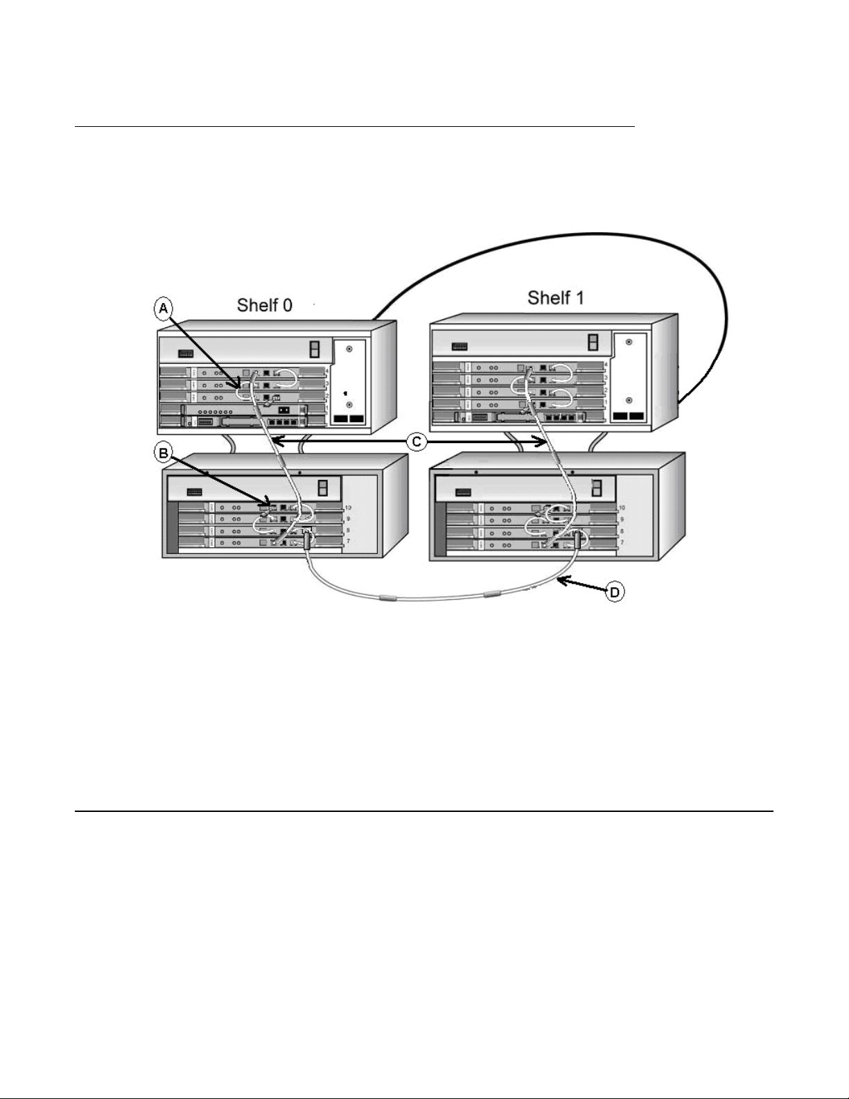
Figure 12: IPE inter-shelf faceplate cabling
The above figure shows:
a IPE DECT shelf 0
b IPE DECT shelf 1
c DMC-E to DMC-E faceplate cable connection between DMC-Es on DECT IPE
shelves (NTCW1
1EA)
24 DMC DECT Fundamentals August 2012
Comments? infodev@avaya.com
Page 25
MG1000E Chassis faceplate cabling
The following figure describes the MG1000E Chassis faceplate cabling.
Figure 13: MG1000E Chassis faceplate cabling
Basestations
Faceplate cables shown on the figure are:
a DMC to DMC faceplate cable (NTCW11AA)
b Faceplate termination (NTCW11DA)
c DMC to DMC 1-meter faceplate cable with four ferrites (NTCW11FA)
d DMC-E to DMC-E faceplate cable connection between two shelves (NTCW11EA)
Basestations
There are three basestation models available:
C4600 – supports six active call radio links
•
• C4610 – supports 12 active call radio links
• C4610E (with external antenna) – supports 12 active call radio links
DMC DECT Fundamentals August 2012 25
Page 26

Product description
Basestations are IP40-compliant wall-mounted transceivers that provide digital radio links to
handsets.
Caution:
Service Interruption
For maximum line length before signal degradation occurs, use UTP
Cat 5 cabling between
the basestation and the shelf or cabinet. If the line length exceeds 100 ohms for the 4610
basestation, an external power supply must be used. The maximum distance when using
external power with UTP Cat 5 cabling is approximately 1.7 km.
The basestation has the following features:
• RJ45 socket connection to a one meter UTP Cat 5 cable
• RJ45 socket connection to an external or local power supply
• Green LED (C4600) or a yellow LED (C4610), indicates synchronization to its DMC8
• One meter UTP Cat 5 cable connected through an RJ45 Connect Box and MDF to an
IPE I/O panel or CS 1000E cabinet I/O panel
Two sources can power the basestation:
• The DMC8 and DMC8-E feeding phantom power over the UTP Cat 5 cable signaling
pairs, connected to (a) in
•
A local power supply, connected to (b) in
Figure 14: Basestation on page 26
Figure 14: Basestation on page 26
Figure 14: Basestation
Basestations connected to a DMC8 or DMC8-E card can use phantom power in some
conditions, and must use local power in other conditions.
An application on the DMC DECT
Manager can enable or disable phantom power.
Note:
The maximum line length for a twelve-channel basestation using phantom power is 1.0 km.
The maximum line length for a six-channel basestation, regardless of power
, or a twelve-
channel basestation using external power, is 1.7 km.
26 DMC DECT Fundamentals August 2012
Comments? infodev@avaya.com
Page 27

Basestation housing
Basestations
The basestation environmental housing is IP66 compliant.
if a basestation is subject to conductive pollution, or outdoors if basestations are mounted
externally.
The housing must be used indoors
Figure 15: Basestation environmental housing
The environmental housing kit includes all of the relevant cables and installation material. The
environmental housing mounts to existing walls. Signaling lines provide power to the external
basestations.
Basestation cell
basestation cell is the radio signal area covered by a single basestation. The basestations
A
are positioned so the cells overlap. A DECT handset can make and receive calls when within
a basestation cell. When the handset moves from one cell to another, the cell overlap allows
the handset to move without interruptions.
DMC DECT Fundamentals August 2012 27
Page 28

Product description
Figure 16: Basestation cell
The cell radius varies from 20m to 100m.
The number of basestations required to cover a certain area depends on many factors, such
as the following:
Size of the area of coverage
•
• Radio propagation characteristics of the buildings
• Materials used for walls, floors, lift shafts, reinforced glass, doors
• Strong magnetic fields from radar, welding equipment, manufacturing equipment, and
high energy electronic devices
• Density of telephone users in an area, and amount of telephone traffic
DECT handset subscription and de-subscription
Subscription is the process of adding a handset to a DECT
make and receive calls.
system. The handset can then
A user can subscribe a handset to more than one DECT system. This feature is useful for a
company that has multiple DECT sites.
De-subscription is the process of removing a handset from a DECT system. The handset user
is then prevented from making and receiving calls.
28 DMC DECT Fundamentals August 2012
Comments? infodev@avaya.com
Page 29

Note:
Refer to each DECT Handset User Guide for a detailed description of how to use handset
features and system features.
DMC DECT Manager
DMC DECT Manager
The DMC DECT
an A vaya CS system. DMC DECT Manager 2.0 runs on Windows 2000 Server , Windows 2000
Professional, Windows XP Professional, Windows Server 2003, and Windows 7.
Note:
For an overview of the DMC DECT
Communication Server 1000 (NN43001-142).
Manager provides a point of access and control to manage DECT system on
DECT Application features
The DECT
• Launch the Application from DMC DECT Manager using Windows and Web navigators
• View DECT provisioning using the DECT Systems window
• View the DMC8 configuration using the Boards window
• View basestation configuration using the Radio Fixed Part window
• View subscription information using the Subscriptions window
• Upgrade firmware using the DECT Systems window
Application allows a user to:
Manager, see Using the DMC DECT Manager Avaya
• Subscribe handsets using the Subscription window
• Support DMC8 and DMC (serial only) cards
• Synchronize (update) the DECT Application database to the DECT system configuration
when the DMC DECT Manager connects to the DECT system
• Collect performance data using the Performance Collection window
• View On-line Help
DMC DECT Fundamentals August 2012 29
Page 30

Product description
Common Services
The following DECT
• DMC DECT Manager Alarm Management provides alarm collection and alarm
processing, as well as the following:
- a Windows-based alarm browser to view alarms that occur while the browser is open
- an Alarm Notification application to notify personnel of an alarm occurrence by pager
or e-mail. This application can forward the alarm to an upstream processor
- a PC Event log and Viewer to view events and alarms generated from the DECT
Application in a report layout
• Backup and restore to create and restore a DMC DECT Manager backup file of the DECT
application data
• User profiles to enable configuration of different types of DECT users
• On-line help to provide help for common services features
For more information about the Common Services features, see Using the DMC DECT
Manager Avaya Communication Server 1000 (NN43001-142).
management features are provided by DMC DECT Manager Applications:
Remote Access Service (RAS)
A
computer in a network provides access to remote users through analogue modem or ISDN
connections. The computer includes the dial-up protocols and access control (authentication),
and can be a regular file server with remote access software or a proprietary system. The
modems can be internal or external to the device.
ISDN is an international telecommunications standard for providing a digital service from the
customer's premises to the dial-up telephone network.
30 DMC DECT Fundamentals August 2012
Comments? infodev@avaya.com
Page 31

DMC DECT Manager
Figure 17: Local DMC DECT Manager server access to a DECT system by V.24
DMC DECT Fundamentals August 2012 31
Page 32

Product description
Figure 18: Local DMC DECT Manager server access to a DECT system by dedicated LAN
Multi-site Mobility Networking subscriptions
In Multi-site Mobility Networking (MSMN), users can take their DECT
in the network, and make and receive calls as if they were at their home location. A handset
is subscribed in a given DECT system and can be used in one or many DECT systems.
For information on MSMN feature description, feature interaction, feature packaging, and
operating parameters. For information on MSMN feature implementation and operation.
Every handset has a Portable Access Rights Key (PARK). Every DECT system has a Primary
Access Rights Identifier (PARI), and can have a Secondary Access Rights Identifier (SARI).
The handset PARK and DECT system PARI and SARI are used by the handset and DECT
system to identify each other. The P ARK and PARI/SARI match allow the handset to work with
a DECT system.
In an MSMN network, for example, DECT system A" has a PARI matching a handset PARK
while DECT systems B," C," and D" have a SARI matching the handset PARK.
handsets to other sites
32 DMC DECT Fundamentals August 2012
Comments? infodev@avaya.com
Page 33

Multi-site Mobility Networking
The DECT Manager user programs the SARI in the DECT system. The DECT Manager
provides the P ARK during the on-air subscription, and the P ARK is programed into the handset
at subscription time.
For example, a handset can be subscribed to a DECT system on the premises of a distributor ,
where the handset is not to be in operation. Then the subscription data is downloaded to a
DECT system where the handset is to be in operation. The PARI, where the handset is
subscribed, and the SARI, where the handset is used, are not always the same. The PARK
matching the destination DECT system to the handset is provided during the on-air
subscription.
Figure 19: DECT Default Subscription ARI dialog box
The DECT
Multi-site Mobility Networking and Subscription on the distributor premises. The ARI normally
defaults to the ARI of the system where the on-air subscription occurs. For MSMN, the default
ARI must be equal to the network SARI value for any subscription activity to take place.
Manager provides the ability to specify the ARI given to the handset, to support
Multi-site Mobility Networking
Multi-site Mobility Networking (MSMN) allows a DECT
at any MCDN node. When the handset user visits a MCDN node, the MSMN feature
automatically performs the following actions:
• Detects the visiting handset when it is on.
• Forwards calls to the visiting handset from the users home node.
The Call Forward dial tone indicates when MSMN activation was not successful. Turn the
handset off and on again to re-activate the MSMN feature.
The MSMN feature requires concentrated DMCs. A concentrated system has each handset
configured to a Virtual TN (VTN) on phantom loops. Concentration allows up to 510 handsets
to share the DMCs 32 time slots and is a blocking system. See
page 37.
handset user to make and receive calls
System concentration traffic on
DMC DECT Fundamentals August 2012 33
Page 34

Product description
Operating parameters
All DMCs, either new
least one handset configured to ensure system operation.
, empty for redundancy, or used for basestation coverage, must have at
Call forward from a MADN handset
A
MADN handset at a remote node can activate Call Forward (CFW) at the home node. When
the handset shares a DN with another sets, the CFW lamp lights on the shared DN sets. If the
handset is not the MARP, the shared DN MARP set can cancel call forward. If the handset is
the MARP, the handset overrides any call forward that is set up from other shared DN sets.
Card audit
Card audit does not work with VTNs.
Network Message Service
The MSMN feature does not change the handling of unanswered network calls.
CallPilot® network mail service does not change with multiple DNs configured against a single
mailbox. The visiting DN receives the Message Waiting Indication (MWI) at the visited site.
The Avaya
Feature packaging
The MSMN feature requires the following packages:
•
Multi-site Mobility Networking (MSMN) package 370.
• Meridian 1 Companion Option (MCMO) package 240.
• Phantom TN (PHTN) package 254.
• Meridian Companion Enhanced Capacity (MC32) package 350.
• Flexible Feature Codes (FFC) package 139.
34 DMC DECT Fundamentals August 2012
Comments? infodev@avaya.com
Page 35

Messaging and Alarms
Messenger provides text messaging from many different sources to various output
DECT
devices, including DECT handsets. Messages can be sent from the following sources:
• external alarm systems, for example nurse call, building alarms, process control
• a mechanical system
• the web or email
• a DECT handset
• contact panels, door switches etc.
It is possible to send the messages to e-mail, pagers and GSM handsets as well as to DECT
handsets, either as escalations if the DECT handset is not available or in parallel.
Messaging and Alarms
Figure 20: DECT Messager connections
DMC DECT Fundamentals August 2012 35
Page 36

Product description
36 DMC DECT Fundamentals August 2012
Comments? infodev@avaya.com
Page 37

Chapter 3: Engineering guidelines
Contents
This section contains information on the following topics:
System capabilities and limits on page 37
DMC8 engineering guidelines on page 41
System capabilities and limits
This section examines several issues surrounding DECT
about system hardware and software parameters is also provided.
System concentration traffic
DECT system without concentration supports a maximum number of 1024 handsets. With
A
the concentration feature, in theory , the handset limit is 510 per DECT Mobility Card x 32 cards
= 16320 handsets. However, in practice, traffic limits the number of handsets per card.
Each IPE card slot supports 32 channels of voice and data at the same time through the DS30X
interface. Concentration removes the existing fixed ratio of 32 handsets per DMC.
Blocking
Calls in DECT
• At the basestation – when all channels (6 or 12) of an basestation are in use, calls through
that basestation (both to and from a Portable Part [PP]) are rejected.
• At the Backbone interface – when the basestations of one DMC together have 32 radio
connections, calls through those basestations (both to and from a handset) are
rejected.
can be blocked at many stages, including the following:
capabilities and limits. Information
DMC DECT Fundamentals August 2012 37
Page 38

Engineering guidelines
• At the IPE backplane interface – when all 32 speech channels to the DS30X interface on
the a DMC8 are occupied, calls to and from handsets that have that specific DMC8 as
their home DMC8 are rejected.
• At the Network interface – usually the IPE shelf connectivity is a blocking configuration,
where the number of network timeslots provided for a shelf is less than the actual number
of terminals configured on that shelf.
Traffic definitions
Busy hour traf
carries the most calls, voice or data. The unit for busy hour traffic is the Erlang or Centi Call
Second (CCS).
Erlang – One Erlang is equal to the continuous use of a circuit for one hour.
CCS – One hundred Call Seconds (CCS) or 100 seconds of continuous use of a circuit.
Normally referred to as CCS per hour. For example, a call on a circuit for one hour is equal to
36 CCS. (60 minutes x 60 seconds = 3600/100 = 36 CCS)
Blocking – A condition when a telephone call does not complete, and the calling party normally
hears a busy signal.
Grade of Service – Grade of Service, given as a decimal fraction, indicates the probability of
call blocking. For most applications, acceptable figures for blocking are between 0.01 and
0.03.
fic – Busy hour traffic is the hour of the day during which a telephone system
Traffic assumptions used for table calculations
The following are traf
• A handset that always has good radio contact with a basestation assumes that the radio
deployment is acceptable.
fic assumptions used for table calculations:
• The Grade of Service used in all calculations is 1%.
• There is little or no overlap between basestations. (In practice, there is overlap, but to
apply standard traffic calculations, it is necessary to simplify the calculation). For example,
two 6-channel basestations in the same cell deliver a higher traffic flow.
• Ignore radio channels for handover. The traffic calculations allocate a slightly higher traffic
capability to a basestation than it can have in practice.
• Blocking occurs at three main areas: the basestations, the backplane, and the network
loops. The traffic calculations only use the Erlang values where blocking occurs. For
example, if there are three areas each delivering 10 Erlangs, traffic calculations take the
total traffic capability as 10 Erlangs, not as 30 Erlangs. Real traffic capacity in this example
is possibly more than 10 Erlangs.
38 DMC DECT Fundamentals August 2012
Comments? infodev@avaya.com
Page 39

• Handset handover continues without interruption.
• Handsets are distributed equally between the system DMC cards.
• All calculations are based on resident handset users. Visiting handset users have a
negligible effect on traffic. In unusual circumstances where a site has a large number of
visiting handset users, traffic capacity can require adjustments.
System hardware parameters
System concentration traffic
The tables in this section detail the minimum and maximum configurations for DECT
Concentration feature.
Table 1: Minimum configuration
System type Cabinets DMC8 DMC8-E Basestation Handset
All systems 1 1 0 1 to 8
††
1 to 510
†
† Due to the maximum number of DCS sets per DMC card. Subject to
engineering rules and constraints.
†† Due to the maximum number of basestations per DMC card. Subject
to engineering rules and constraints.
Table 2: Maximum CS 1000M (Large System) configuration
System type Cabinets DMC8 DMC8-E Basestation Handset
CS 1000M 2 30 2 256
††
16 320
†
† Due to the maximum number of DCS sets per DMC card. Subject to
engineering rules and constraints.
†† Due to the maximum number of basestations per DMC card. Subject
to engineering rules and constraints.
Table 3: Maximum CS 1000E configuration
with the
System type CabinetsDMC8 DMC8-EBasestationHandsetPRI
Cards
MG 1000E
1 5 1 48
††
3060
†
1 3
MC32
Cards
Cabinet / MG
1010E Chassis
(one-shelf
configuration)
MG 1000E
2** 11 2 104
††
6630
†
1 6
Cabinet / MG
1010E Chassis
(two-shelves
configuration)
DMC DECT Fundamentals August 2012 39
Page 40

Engineering guidelines
System type CabinetsDMC8 DMC8-EBasestationHandsetPRI
MG 1000E
2 4 1 40
††
2550
†
Chassis with
Expander (one-
shelf
configuration)
MG 1000E
4** 9 2 88
††
5610
†
Chassis with
Expander (two-
shelves
configuration)
MG 1000E IPE
1 13 1 112
††
7140
†
shelf –MG XPEC
(one-shelf
configuration)
MG 1000E IPE
2** 26 2 224
††
14280
†
shelf –MG XPEC
(two-shelves
configuration)
** Clock synchronization with the main cabinet or MG is
mandatory
. ** Clock synchronization with the main
cabinet or MG is mandatory. See section “Overview
Avaya Communication Server 1000E” for details.
† Due to the maximum number of DCS sets per DMC
card. Subject to engineering rules and constraints.
†† Due to the maximum number of basestations per
DMC card. Subject to engineering rules and
constraints.
Cards
1 2
1 4
0 2
0 4
MC32
Cards
For CS 1000E systems (MGC based), a clock controller must be installed in the cabinet.
Therefore you must install a PRI card with a NTAK20 Clock Controller Daughterboard.
A Media Gateway Card (MGC) installed in an MG 1000 chassis (with MG 1000E Expander),
or an MG 1010E chassis provides 128 DSP ports. The maximum number of simultaneous calls
between the trunks or lines connected to this Media Gateway , including DECT sets subscribed
to DMC cards in this chassis, and any endpoints outside the Media Gateway is limited to
128.
Each DMC card supports up to 32 DSP ports. For a non-blocking call solution, the maximum
number of DMC cards that can be installed in an MG 1000 / MG 1010E is limited to four. If four
are not sufficient, an extra MC 32 card is required for each additional DMC card. A non-blocking
solution for a DECT system requires special planning in terms of the available channels on the
basestations covering certain areas as well as the distribution of DCS blocks among the DMC
cards available in the system.
If a cabinet or Media Gateway has a number 9 slot, it must be provisioned with a DMC8-E card.
All other cards are DMC8s.
40 DMC DECT Fundamentals August 2012
Comments? infodev@avaya.com
Page 41

The DECT system components have the following capacities:
• One NTCW00AB DMC8 or one NTCW01AB DMC8-E can support up to 8 basestations.
• One C4600 basestation can support 6 active calls.
• One C4610 basestation can support 12 active calls.
• One C4610E basestation can support 12 active calls.
Multiple DECT systems can co-exist in the same PBX system if they are synchronized to the
same clock source. However, from a user perspective, the DECT systems are separate.
System software parameters
DMC8 engineering guidelines
The software that operates the DECT
consists of an operating program and a system database configuration. The operating program
controls basestation and handset functions. The operating program also communicates with
the system and the DMC DECT Manager. The system data defines hardware and hardware
addressing.
The DMC8/DMC8-E with the ensuing software releases supports the following:
• Release 23 can support basic configuration, CLID and CPND, DECT card addressing
within OA&M, and 16 users on each card.
• Release 24.2x can support up to 32 handsets on each card.
Release 25.xx can support up to 510 handsets with Concentration and MSMN.
The firmware on the DMCs will support CLID, but there is no official way in DECT to tell that
the connected party or CLID has changed. This is a limitation to the DECT standard.
system resides as firmware in the DMCs. The firmware
DMC8 engineering guidelines
This section describes the recommended engineering guidelines for the installation of phantom
powered basestations.
The optimum capacity mix of 6-channel and 12-channel basestations is six 6-channel and two
12-channel basestations. Using three or more 12-channel basestations per DMC8 is possible
but is not an ef
Avaya recommends that the 12-channel basestations be distributed over the DMC8s.
Table 4: DMC8 engineering guidelines for 6-channel RFP (basestation) and 12-channel RFP
(basestation) on page 42 The following table lists engineering guidelines for various
deployments of phantom-powered basestations.
DMC DECT Fundamentals August 2012 41
ficient use of the 32 channels of the DMC8.
Page 42

Engineering guidelines
Table 4: DMC8 engineering guidelines for 6-channel RFP (basestation) and 12-channel
RFP (basestation)
System Number of basestations that can be phantom powered
per shelf or cabinet
Large System
Cabinet
Chassis
eight 6-channel or six 6-channel + two 12-channel @ 0.5
km
seven 6-channel or five 6-channel + two 12-channel @1.0
km
seven 6-channel @ 1.7 km 112
new basestations – any mix at 1.7 km 128
seven 6-channel or five 6-channel + two 12-channel @ 0.5
km
six 6-channel or four 6-channel + two 12-channel @1.0 km 60
six 6-channel @ 1.7 km 60
new basestations – any mix at 1.7 km 80
eight 6-channel or six 6-channel + two 12-channel @ 0.5
km
eight 6-channel or six 6-channel + two 12-channel @ 1.0
km
eight 6-channel @ 1.7 km 32
Total
128
112
70
32
32
new basestations – any mix at 1.7 km 32
CS 1000E
eight 6-channel or six 6-channel + two 12-channel @ 0.5
km
eight 6-channel or six 6-channel + two 12-channel @ 1.0
km
eight 6-channel @ 1.7 km 32
new basestations – any mix at 1.7 km 32
32
32
Using the maximum of eight basestations on a DMC8 imposes engineering restrictions on the
remaining slots, as listed in Table 5: DMC8 Ordering Tool - system slot restrictions for different
basestation lengths on page 42.
T able 5: DMC8 Ordering Tool - system slot restrictions for different basestation lengths
System Basestation
average line
length
Large System 0.5 km no restrictions
1.0 km
Required number of unoccupied slots
for every 1 – 15 slots, one slot must be unoccupied
42 DMC DECT Fundamentals August 2012
Comments? infodev@avaya.com
Page 43

DMC8 engineering guidelines
System Basestation
1.7km for every 1 – 6 slots, one slot must be unoccupied
Cabinet 0.5 km for every 1 – 9 slots, one slot must be unoccupied
1.0 km for every 1 – 8 slots, one slot must be unoccupied
1.7km for every 1 – 15 slots, one slot must be unoccupied
Chassis 0.5 km no restrictions
1.0 km no restrictions
1.7km no restrictions
0.5 km no restrictions
CS 1000E
1.0 km no restrictions
1.7km no restrictions
Netprice Order Tool
Required number of unoccupied slots
average line
length
The Netprice Order
Tool makes certain approximations in provisioning DMC8. This provides
a simplified configuration that meets the needs of most sites.
DECT on Large Systems
The Order
basestations are requested, the extra basestations are assumed to be local powered. Power
adapters are provided as follows:
• C4610 AC adapters = (sum of 6-channel and 12-channel basestations) – 80
• Adapters must be purchased separately
Tool allows the first 80 basestations to be phantom powered. When more than 80
Note:
Because it is not possible to determine how the cards are spread over the two shelves,
it is assumed that there are 80 phantom powered basestations per system.
DMC DECT Fundamentals August 2012 43
Page 44

Engineering guidelines
DECT on Cabinet system
The Order
basestations are requested, the extra basestations are assumed to be local powered. Power
adapters are provided as follows:
• C4610 AC adapters = (sum of 6-channel and 12-channel basestations) – 80
• Adapters must be purchased separately
Tool allows the first 40 basestations to be phantom powered. When more than 40
DECT on Chassis system
All basestations can be powered from the cabinet power supply
DECT on CS 1000E
All basestations can be powered from the Media Gateway power supply
Rules with new basestations
With the new basestations, the provisioning rules are relaxed to allow the maximum number
of basestations to be provisioned for each shelf, without the requirements.
.
.
Basestation combinations for handsets on a DMC8
Low traffic for a 0.1 Erlang capacity
Table 6: Number of handsets for a 0.1 Erlang capacity on page 44 shows the 6-channel and
12-channel basestation combinations required to support a maximum number of handsets on
a DMC card. The calculations are based on each handset generating 0.1 Erlangs of traffic.
Table 6: Number of handsets for a 0.1 Erlang capacity
Number of 6channel base
stations
44 DMC DECT Fundamentals August 2012
0 1 2 3 4 5 6 7 8
Number of 12-channel basestations
Comments? infodev@avaya.com
Page 45

Basestation combinations for handsets on a DMC8
0 0 58 117 176 176 220 220 220 220
1 19 77 136 195 220 220 220 220
2 38 97 155 214 220 220 220
3 57 116 174 220 220 220
4 76 135 194 220 220
5 95 154 213 220
6 114 173 220
7 133 192
8 152
Medium traffic for a 0.15 Erlang capacity
Table 7: Number of handsets for a 0.15 Erlang capacity on page 45 shows the 6-channel
and 12-channel basestation combinations required to support a maximum number of handsets
on a DMC card. The calculations are based on each handset generating 0.15 Erlangs of
traffic.
Table 7: Number of handsets for a 0.15 Erlang capacity
Number of 12-channel basestations
0 1 2 3 4 5 6 7 8
0 0 0 39 78 117 146 146 146 146
1 12 51 91 130 146 146 146 146
2 25 64 103 143 146 146 146
3 38 77 116 146 146 146
4 50 90 129 146 146
5 30 102 146 146
6 76 115
Number of 6channel base
stations
7 89 128
8 101
DMC DECT Fundamentals August 2012 45
Page 46

Engineering guidelines
High traffic for a 0.2 Erlang capacity
Table 8: Number of handsets for a 0.2 Erlang capacity on page 46 shows the 6-channel and
12-channel basestation combinations required to support a maximum number of handsets on
a DMC card.
Table 8: Number of handsets for a 0.2 Erlang capacity
The calculations are based on each handset generating 0.2 Erlangs of traffic.
Number of 12-channel basestations
0 1 2 3 4 5 6 7 8
0 0 0 29 58 88 110 110 110 110
1 9 38 68 97 110 110 110 110
2 19 48 77 107 110 110 110
3 28 58 87 110 110 110
4 38 67 97 110 110
5 47 77 106 110
6 57 86 110
Number of 6channel base
stations
7 66 96
8 76
Superloop and IPE shelf calculations
Table 9: Handset capacity/DMC8 for Superloop/IPE on page 46 shows the maximum number
of handset users on a DMC8 card for varying traffic levels.
Table 9: Handset capacity/DMC8 for Superloop/IPE
Superloops per IPE
shelf
2 138 handsets/DMC 92 handsets/DMC 69 handsets/DMC
1 69 handsets/DMC 46 handsets/DMC 34 handsets/DMC
0.5 34 handsets/DMC 23 handsets/DMC 17 handsets/DMC
Cabinet system 220 handsets/DMC 146 handsets/DMC 110 handsets/DMC
Low traffic 0.1
Erlang
Medium traffic 0.15
Erlang
High traffic 0.2
Erlang
Note:
Superloops do not apply to Chassis systems or CS 1000E systems.
46 DMC DECT Fundamentals August 2012
Comments? infodev@avaya.com
Page 47

Simplified guidelines
Use T able 9: Handset capacity/DMC8 for Superloop/IPE on page 46 to calculate the superloop
capacity
Low traffic example of one superloop on each IPE shelf
• Sixty-nine (69) handsets per DMC8 card x 16 DMC8 cards per shelf = 1104 (1000)
Medium traffic example of one superloop on each IPE shelf
• Forty-six (46) handsets per DMC8 card x 16 DMC8 cards per shelf = 736 (750)
High traffic example of one superloop on each IPE shelf
• Thirty-four (34) handsets per DMC8 card x 16 DMC8 cards per shelf = 544 (500)
.
Basestation combinations for handsets on a DMC8
DMC DECT Fundamentals August 2012 47
Page 48

Engineering guidelines
48 DMC DECT Fundamentals August 2012
Comments? infodev@avaya.com
Page 49

Chapter 4: Site planning
Contents
This section contains information on the following topics:
Overview on page 49
Site survey on page 50
Deployment on page 58
Deployment tool on page 76
How to use the deployment tool on page 86
DECT Deployment Kit 2 on page 87
Deploying DECT on page 91
Correcting problems with audio quality on page
Deploying an external basestation on page
Single and multiple floor deployment on page
Cell re-engineering for high traffic areas on page
Cell division requirements in special cases on page 1
High handset density deployment on page 1
Deployment review on page
Overview
Site planning starts with a site survey and ends with deployment.
an information gathering process. The information received in the site survey determines
customer requirements and the number of cells required to support traffic.
Deployment is the process of locating basestations at the site. The module titled
basestation on page
94
95
96
106
14
17
119
The site survey process is
Installing the
128 contains general information about the deployment process. This
DMC DECT Fundamentals August 2012 49
Page 50

Site planning
module includes information about a key piece of deployment equipment, the DECT Radio
Deployment Tool. The section titled Preparing the tool for deployment on page 78
how to prepare equipment for deployment.
Other modules describe in detail the procedures related to deployment. These procedures vary
according to site details and user requirements.
Site survey
explains
The site survey begins by researching the customer requirements.
variety of information such as contact names, the number of handset users, and building
details.
Customer requirements
The customer must provide:
1.
a site contact name and telephone number;
2. site plans;
3. building details;
4. information on available house cabling;
5. radio coverage requirements; and,
6. number of users.
On-site contact
The on-site contact provides:
The research identifies a
1. time and date scheduling;
2. access to restricted or locked areas; and,
3. additional information when required.
Site plans
A complete set of site plans are required. Dimensions must be clearly stated on the plans.
50 DMC DECT Fundamentals August 2012
Comments? infodev@avaya.com
Page 51

Building details
System deployment and installation depends upon the following building details.
•
Building identification
• Construction materials, such as walls, floors, ceilings
• Type of use, such as an office, hotel, factory, or store
• Dimensions
• Number of floors
• Height of floors
• Partitioning of floors
Position and use of available cabling
Cables that connect the basestation to the DECT system must meet or exceed the UTP Cat
3 standard. Avaya recommends UTP Cat 5, as it provides a greater line length before signal
degradation occurs. New cabling is required if the existing cabling does not meet the
standard.
Site survey
Radio coverage
A basestation coverage list is required to indicate:
a areas where radio coverage is required;
b areas excluded from radio coverage due to the proximity of sensitive electronic
c areas where radio coverage is not required;
d areas where radio coverage is not feasible or requires specific basestations;
e objects inside buildings; and,
f details of furniture, cupboards, and machinery on every floor of the building
Basestation installations can be required to be out of sight. A customer can request
basestations to be mounted in unsuitable locations, such as stone columns, air ducts or
horizontally on the ceiling. Radio coverage cannot be guaranteed when basestations are
mounted in unsuitable locations.
equipment;
DMC DECT Fundamentals August 2012 51
Page 52

Site planning
Know in advance where coverage is required. Some examples of coverage areas are:
• elevators
• stairwells
• toilets
• outdoor areas
Number of handset users
The following information must be available.
1. The number of handset users
2. The potential growth of handset users
3. The areas of above average and below average traffic density Number of cells
required to support traffic
Traffic requirements are determined for each cell. The deployer calculates system
requirements to support user traffic.
Customer review
After the site survey and before the deployment process, the person deploying the site must
review coverage requirements with the customer representative. The person deploying the site
must explain to the customer representative how the survey is conducted. The customer
representative must tell fellow employees that a person deploying the site is taking
measurements in their work place.
Site survey example
The site survey process is an information gathering process.
site survey determines customer requirements and the number of cells required to support
traffic.
A normal site survey
The site survey process includes gathering:
1. Survey materials
2. Site contact information
The information received in the
3. Site plans or maps
52 DMC DECT Fundamentals August 2012
Comments? infodev@avaya.com
Page 53

4. Building information
5. Existing cable information
6. Basestation radio coverage information
7. Handset user information
8. Reviewing the work
Methods and examples for surveying more detailed sites are shown in the Detailed Site
Planning section of this guide. Use one or more of the following surveying methods in the site
survey:
• Single floor
• Subsequent system installation
• High handset density area
• Multiple systems installation
Site planning example: Able-Studio
Site survey
This section describes a site survey for
to conduct the site survey.
Able-Studio, a fictitious company . Follow this example
The facts for Able-Studio
• The contact is Rolf Sundby at 555-0000. A guest lab coat is necessary to be on the site.
Get this lab coat from Rolf.
• The sales representative has recommended DECT.
• The location of the user offices (and their wired telephones) often changes within the
coverage area.
• Not all users have offices and desk telephones. Some users only have handsets.
• The customer does not need coverage in the toilet facility.
• The telephone switch room is next to the toilet facility.
• The customer has no installation restrictions.
The site survey process for Able-Studio
The technician must gather the following information to conduct a site survey:
Gather survey items on page 54
1.
2. Identifying site contacts on page 54
DMC DECT Fundamentals August 2012 53
Page 54

Site planning
3. Obtaining site plans on page 55
4. Gathering building information on page 55
5. Identifying existing cabling on page 56
6. Profiling handset use on page 57
Gather survey items
Obtain the following items before beginning the site survey
. The items are not customer
supplied.
• Pick up the DECT tool kit (consisting of tripod and deployment tool kit).
• Get the appropriate DECT Provisioning Record.
• Gather a pencil, an eraser, a ruler, and coloured pencils.
Identifying site contacts
Gather the following information and enter it into the work-order and the Provisioning records.
The installer requires the following information.
Identifying site contacts
1. Get the company name.
Record this information.
2. Get the company address.
Record this information.
3. Contact name.
Record this information.
4. Obtain the contact telephone number.
Record this information.
5. Obtain scheduling times and date.
Record this information.
6. Access to controlled areas.
Record this information.
7. Obtain any keys or codes needed for secured site areas where radio coverage is
required.
8. Obtain additional contact information, if required.
Record this information.
9. Obtain any required safety equipment, such as a hard hat or safety glasses.
10. Find out if there is an another DECT system within the radio coverage area.
Record this information.
54 DMC DECT Fundamentals August 2012
Comments? infodev@avaya.com
Page 55

Site survey
Obtaining site plans
Obtain two scaled plans. The scale is required to check wiring distances from the controller to
the basestations. The scale is in the form of a measured line so that it remains in proportion
to the floor plan through reduction copiers.
Figure 21: Example of a site coverage floor plan
Obtaining site plans
Obtain two site plans/maps, with dimensions marked.
One working copy to identify critical points, cell centres, and cell boundaries. One clean
copy to attach to the site Provisioning Record for the installer
maintenance.
Gathering building information
Gather the following information and enter it into the work-order.
Gathering building information
1. Obtain building identification.
Record this information.
2. Obtain information on construction materials, such as walls, floors, ceilings.
Record this information.
3. Note the type of use of facilities, such as office, hotel, factory, store.
Record this information.
4. Find the number of floors.
, customer, or
DMC DECT Fundamentals August 2012 55
Page 56

Site planning
Record this information. If the building contains atriums, multiple floors, floors not
all the same shape or any unusual conditions, see Multiple floor deployment on
102.
page
5. Find the height of floors.
Record this information.
6. Ask about the partitioning of floors.
Record this information.
7. Discuss the details of furniture, cupboards, and machinery in the interior of buildings
on every floor.
Record this information.
8. Ask about other building details, as necessary.
Record this information.
Identifying existing cabling
Gather the following information and enter it into the work-order.
Identifying existing cabling
1. Obtain the location of the telephone switching room.
Determine the total length of the cable.
2. Ask about the existing cabling for basestation to MDF wiring.
Wiring from the basestation to the shelf or cabinet must be at least UTP Cat 3. Avaya
recommends UTP Cat 5, as it provides greater line length before signal degradation
occurs.
3. Review the possibility of new UTP Cat 5 cabling required.
If the cabling is not at least UTP Cat 3, have UTP Cat 5 installed.
Assessing radio coverage
Note:
If the customer requires the basestations be installed out of sight, this can reduce the
coverage capability of each basestation. It can limit the performance of the system and
substantially increase the cost.
Gather the following information and enter it into the work-order
.
Assessing radio coverage
1. Inquire about areas where radio coverage is required.
Record this information.
2. Ask about areas where radio coverage is not required.
Record this information.
56 DMC DECT Fundamentals August 2012
Comments? infodev@avaya.com
Page 57

Site survey
3. Ask about external or outdoor radio coverage.
Record this information.
Discuss areas where radio coverage is not feasible or requires specific
4.
basestations.
Record this information.
5. Discuss areas excluded from radio coverage due to the proximity of sensitive
electronic equipment.
Record this information.
6. Ask about objects inside buildings that can affect radio coverage.
Record this information.
7. Discuss unsuitable basestation locations, such as stone columns, air ducts or
horizontally on the ceiling.
8. Discuss what basestations are to be installed out of sight.
Discuss with the customer. See the preceding note.
9. Inquire about areas of special coverage, such as, elevators, stairwells, toilets.
Profiling handset use
Areas of above average traffic density can have a low number of incumbent users but many
incoming users. These can include areas such as cafeterias, restaurants, canteens, and
meeting room areas where handset users tend to gather.
A further example of above average traf fic density is an environment where all occupants of a
given area are provided with handsets. This area requires special planning.
Areas of below average traffic density are areas infrequently accessed by users, such as store
rooms and maintenance areas.
Obtain the following information and enter it into the work-order.
Profiling handset users
1. Document the number of handset users.
Record this information.
2. Get an estimate of the potential growth of handset users.
Record this information.
3. Locate areas of above average and below average traffic density.
Record this information. See the preceding note.
4. Determine which users have a wired telephone in their office.
Record this information.
5. Determine the locations of user offices.
DMC DECT Fundamentals August 2012 57
Page 58

Site planning
6.
Deployment
deployment determines the locations of basestations and cells. The deployment process
A
consists of the following steps.
•
Identifying initial critical points on the floor plan on page 58.
• Locating cell centres on page 59.
• Determining cell boundaries on page 61.
• Identifying critical points and cell boundaries on page 62.
Record this information.
Ask about the mobility of the users. For example, do the users move from cell to
cell, or is the area of movement restricted, such that the users remain within one
cell?
Record this information.
• Marking the points, centres, and boundaries on the floor plan on page 63.
Identifying initial critical points on the floor plan
A
critical point is a place that can be difficult for the radio signal to reach, such as a corner of
a room, lifts and stairwells. Initial critical points are shown in
page 59
Figure 22: Critical points on page
as P1, P2, P3, and P4.
59 shows the following:
• stairwell
• second floor plan
Figure 22: Critical points on
58 DMC DECT Fundamentals August 2012
Comments? infodev@avaya.com
Page 59

Figure 22: Critical points
Deployment
Locating cell centres
Figure 23: Cell centres on page
• stairwell
• second floor plan
A cell centre is located by placing the deployment tool at one critical point, for example P1,
then using the deployment handset to obtain a change in audio quality. The audio quality
change determines the cell boundary contour. This process is repeated at an adjacent critical
point, for example P2. Where the cell boundaries of both critical points meet is the cell centre.
The cell centre position is marked on a floor plan. The cell centre determines the location of a
basestation, shown in
60 shows the following:
Figure 23: Cell centres on page
60, as arc 2C1.
DMC DECT Fundamentals August 2012 59
Page 60

Site planning
Figure 23: Cell centres
Rules and guidelines for selecting cell centres
Comply with the following when selecting cell centres.
Ensure that the installation complies with local electrical codes.
•
• Install basestations indoors where there is no condensation and the temperature remains
between 0°C and 50°C.
• Install basestations within 1500 metres of the MDF. Wiring from the basestation to the
shelf or cabinet must be at least UTP Cat 3. Avaya recommends UTP Cat 5, as it provides
a greater line length before signal degradation occurs.
• Position basestations upright on walls. Basestations must be at least 30 centimeters from
the ceiling.
• Position basestations at least 1 m from large concrete or stone columns and from any
major building structural members such as support beams or columns.
• Position the basestations high enough to clear obstructions between the basestations
and the cell edge close to the ceiling.
• Mount the basestations clear of obstacles such as pipes or ducts.
• Do not install basestations in spaces that transport air, such as ducts or plenums.
• Do not mount basestations on the ceiling.
60 DMC DECT Fundamentals August 2012
Comments? infodev@avaya.com
Page 61

Determining cell boundaries
A
specific RSSI value on the handset defines the cell boundary range. Links can be made
outside the cell boundary but the audio quality of the link is poor. The link drops when the
handset and the basestation are too far apart.
Deployment
As shown in
furthest point from the cell centre where a clear radio signal can be heard.
The range from the cell centre to the cell boundary, or the distance to a potential cell centre
from a critical point, is determined by using the cell boundary value and the deployment tool.
Figure 24: Cell boundary terminology on page
61, the cell boundary is the
Figure 24: Cell boundary terminology
Figure 25: Cell boundaries on page
A cell boundary for the cell centre is determined by placing the deployment tool at the cell
centre, for example 2C1, and using the deployment handset to establish the cell boundary.
The cell boundary contour is marked on the floor plan, and shown in
boundaries on page
DMC DECT Fundamentals August 2012 61
62 by a dash-dot line.
62 shows the following:
Figure 25: Cell
Page 62

Site planning
Figure 25: Cell boundaries
Identifying critical points and cell boundaries
Figure 26: Additional critical points and cell boundaries on page 63 shows the following:
stairwell
•
• second floor plan
Additional critical points, shown in
63 as P5, P6, P7, and P8, are identified to ensure basestation radio coverage for the
page
entire area.
Figure 26: Additional critical points and cell boundaries on
62 DMC DECT Fundamentals August 2012
Comments? infodev@avaya.com
Page 63

Figure 26: Additional critical points and cell boundaries
Deployment
Marking the points, centres, and boundaries on the floor plan
This section describes how to label critical points, cell centres, and cell boundaries on the floor
plan.
Mark the information clearly on the floor plans during the survey
the installer, and maintenance personnel must read these floor plans.
Use a different colour for each cell. Use the same colour for each cell centre and its
corresponding cell boundaries. Indicate the information on the floor plan as follows:
• critical points – mark the following on the floor plan:
Figure 27: Critical point marker
cell centres – mark the following on the floor plan:
•
Figure 28: Cell centres marker
cell centre - label each as xCn where x is the floor and n is the next sequential cell
•
centre.
• cell boundaries – mark wide, coloured lines on the floor plan.
. The customer , the sales group,
DMC DECT Fundamentals August 2012 63
Page 64

Site planning
For example, label a cell centre on the second floor as 2C3. The 2 before the C indicates that
the cell centre is on the second floor. The 3 after the C indicates that this cell is the third cell
in sequence in the site planning process.
Table 10: Example cell labels
Floor Cell label
First floor 2C1, 2C2, 2C3
Ground floor 1C1, 1C2, 1C3
Basement level one –1C1, –1C2, –1C3
Basement level two –2C1, –2C2, –2C3
64 DMC DECT Fundamentals August 2012
Comments? infodev@avaya.com
Page 65

Figure 29: Example cell boundaries
Deployment
Figure 30: Points, centres, and boundaries on the floor plan
Figure 30: Points, centres, and boundaries on the floor plan on page 65 shows a typical floor
plan marked-up after determining subsequent cell boundaries.
The completed floor plan would
appear as follows:
• Initial critical points are shown at P1, P2, P3, and P4.
• Cell centres are located where arcs from P1/P2, P3/P4 intersect.
• 2C1 and 2C2 show cell centres or basestation locations.
• Dashed and dotted lines show cell boundaries.
• Additional critical points are shown at P5 P6 P7 P8.
• 2C3 and 2C4 cell centres provide full coverage of the floor.
DMC DECT Fundamentals August 2012 65
Page 66

Site planning
Two copies of the floor plan are required. One copy is used during the site planning. The second
copy is marked with the information from the site planning copy and attached to Provisioning
records on page 125 for the installer.
Deployment illustrations
The illustrations in this section represent the deployment process from start to finish.
66 DMC DECT Fundamentals August 2012
Comments? infodev@avaya.com
Page 67

Deployment
Figure 31: Example of initial critical points
Figure 32: Cell contour of the initial critical point
DMC DECT Fundamentals August 2012 67
Page 68

Site planning
Figure 33: Cell contour of the closest adjacent critical point to the initial critical point
Figure 34: Example of a cell centre
68 DMC DECT Fundamentals August 2012
Comments? infodev@avaya.com
Page 69

Deployment
Figure 35: Example of a cell centre boundary
Figure 36: Example of new critical points (P8 and P9)
DMC DECT Fundamentals August 2012 69
Page 70

Site planning
Figure 37: Example of deployment for cell centre 1C2
Figure 38: Example of deployment for cells 1C3 and 1C4
70 DMC DECT Fundamentals August 2012
Comments? infodev@avaya.com
Page 71

Deployment
Figure 39: Identify new critical points (P11, P12, P13, P14, P15, P16, P17)
Figure 40: Contours formed by critical points P11, P13 and P16
DMC DECT Fundamentals August 2012 71
Page 72

Site planning
Figure 41: Cell centre 1C5 formed by critical points P11, P13 and P16
Figure 42: Cell boundary 1C5 formed by critical points P11, P13 and P16
72 DMC DECT Fundamentals August 2012
Comments? infodev@avaya.com
Page 73

Deployment
Figure 43: Example of critical point cell boundaries
Figure 44: Example of cell centre boundary 1C6
DMC DECT Fundamentals August 2012 73
Page 74

Site planning
Figure 45: Example of a floor plan showing complete radio coverage
Deployment terms
Terms associated with deployment are listed in the following table.
Table 11: Deployment terms
Term Definition
Coverage area An area where a handset can be used to make and receive
Cell The coverage area provided by the basestation antennas.
Cell boundary The parameter of a cell coverage area.
Critical point A point or location defined as the extreme corner of a coverage
Cell centre The installation point of the basestation serving the cell.
Range The distance from a cell centre to its cell boundary.
Traffic table Traffic tables record site traffic information from the floor plan
calls.
area that can be dif
and the customer. The traffic table helps to determine the
required number of basestations for each cell.
ficult for the radio signal to reach.
The following figure illustrates these terms.
74 DMC DECT Fundamentals August 2012
Comments? infodev@avaya.com
Page 75

Figure 46: Example showing deployment terms
Coverage terms
Deployment
The terms used in this guide are described in
Table 12: Coverage terms on page 75
illustrated in Coverage terms.
Table 12: Coverage terms
Term Definition
Estimated number of
handsets
Cell The coverage area provided by a basestation.
Cell boundary The edge of a cell showing the cell coverage area.
Cell centre The place where all the basestations are installed.
DECT Radio
Deployment
Critical point A point or location defined as an outer corner of a coverage area,
Coverage area The area defined by the customer in which a handset user can
Link When a handset and a basestation are in radio communication
Tool
The average number of handsets expected in a particular cell.
The tool used to determine the radio range of a basestation.
or points that can be difficult for the radio signal to reach.
expect to be able to make and receive calls.
with each other.
and
Range The distance from a cell centre to the cell boundary.
Office The location where a handset user spends the majority of their
day.
DMC DECT Fundamentals August 2012 75
Page 76

Site planning
Term Definition
Traffic table Traffic tables record site traf fic information from the floor plan and
the customer
number of basestations for each cell.
. The traffic table helps to determine the required
Figure 47: Coverage terms
Deployment tool
The DECT
See
Deployment Kit 2 and DeTeWe handsets on page 90.
Deployment Tool (deployment tool) determines cell centres and cell boundaries.
Figure 56: Deployment Kit 2 and carrying case on page 88
and
Figure 57: Assembled
76 DMC DECT Fundamentals August 2012
Comments? infodev@avaya.com
Page 77

Deployment tool
Figure 48: Deployment tool carrying case and packing details
DMC DECT Fundamentals August 2012 77
Page 78

Site planning
Figure 49: Assembled deployment tool
Preparing the tool for deployment
Preparing the tool for deployment involves:
Charging the deployment tool battery on page 79
1.
2. Charging the deployment handset battery on page
Assembling the deployment tool on page 81
3.
4. Testing the deployment handset on page 84
78 DMC DECT Fundamentals August 2012
Comments? infodev@avaya.com
80
Page 79

Charging the deployment tool battery
Charge the deployment tool battery for at least six hours before using.
Caution:
Equipment Damage
Deployment tool
Use the
Avaya battery charger . This charger is a separately ordered item. Failure to use an
automatic shut-off battery charger can damage the battery.
Do not use the battery supplied with the CT2 deployment tool. The CT2 and DECT batteries
are not interchangeable.
Figure 50: Deployment tool battery charger
able 13: Deployment tool battery charger key
T
a battery charger (must be ordered separately)
b battery charger cable
Charging the deployment tool battery
1.
Set up the deployment tool battery charging equipment.
Remove the deployment tool battery, charger, and charger cord from the yellow
case.
2. Charge the deployment tool battery.
Connect the charger cord plug into the battery. Connect the red alligator clip to the
positive lead of the charger, and the black clip to the negative lead of the charger.
Connect the battery charger to the AC mains.
3. Remove the deployment tool battery from the charger after it is charged.
The battery must charge for at least six hours.
DMC DECT Fundamentals August 2012 79
Page 80

Site planning
Charging the deployment handset battery
Figure 51: Deployment handset battery charger
Charging time
Charge the deployment handset battery for at least 12 hours before using the first time. Charge
the handset at least six hours before any subsequent use.
Charging the deployment handset battery
1.
Set up the deployment handset battery charging equipment.
Remove the deployment handset battery , charger and charger cord from the yellow
case.
2. Charge the deployment tool battery.
Connect the charger cord to the charging stand. Connect the charger cord to the
AC mains. Place the handset into the charging stand. The red LED flashes while
the handset is charging.
3. Remove the handset from the charger when it is ready for use.
80 DMC DECT Fundamentals August 2012
Comments? infodev@avaya.com
Page 81

Assembling the deployment tool
Figure 52: Deployment tool extension details
Deployment tool
T
able 14: Key for Assembling the deployment tool
a adjustable tripod
b extender arm connector
c extender arm swivel
d detente stop
e detente
f extension thumb screw
g telescopic extension
h Allen key
i basestation attaching thumb screw
j basestation
Note:
The deployment tool battery and the deployment handset battery must be charged for at
least six hours before use.
DMC DECT Fundamentals August 2012 81
Page 82

Site planning
Figure 53: Deployment tool battery details
T
able 15: Deployment tool battery details key
a battery mount
b Allen screws
c thumb screw
d battery pack
e guides
f thumb screw nut
g power cord
h power cord receptacle
i tripod
Assembling the deployment tool
1.
Set up the tripod.
Remove the tripod from its carrying case and set upright. Lock the casters.
2. If required, install the extension arm fitting on the tripod. If not required, go to step
4.
Place the extension arm fitting, shown in
Figure 56: Deployment Kit 2 and carrying
case on page 88, onto the brass fitting on the top of the tripod.
82 DMC DECT Fundamentals August 2012
Comments? infodev@avaya.com
Page 83

3. If required, secure the extension arm fitting.
Deployment tool
Use the
Allen key attached to the extender arm to secure the extension arm fitting
Allen screw.
4. Mount the extension arm on the tripod.
Place the brass end of the extension arm into the fitting, so that the keying hole of
the extension arm mates with the retaining thump screw locking device of the tripod
fitting. The thumb screw locking device clicks into the keying hole of the extension
arm.
5. Position the extension arm.
Orient the arm into the proper position. Secure the tripod fitting and the extension
arm thumb screw.
6. Affix the basestation to the extension arm.
Remove the basestation from the yellow case. Mount the basestation onto the end
of the arm. Screw the brass thumb screw on the arm into the bottom of the
basestation and secure it in place with the grey lock thumb screw.
7. Position the antenna.
Rotate the antenna from its stowed position, against the body of the basestation, to
its upright operating position.
8. Position the basestation. The normal position is with the antenna pointing
upwards.
Secure the basestation with the arm thumb screw.
9. Mount the battery fixture on the tripod.
Remove the battery bracket, shown in
page 82
, from the yellow case. Screw the battery bracket onto the tripod caster
Figure 53: Deployment tool battery details on
brace, with the two machine screws.
10. Mount the battery.
Pull the release pin on the bracket back and slide the battery grooves on to the
bracket. Ensure the bracket pin locks into the battery.
11. Connect the basestation to the battery.
Plug the basestation power cord connector into the upper right edge of the
battery.
DMC DECT Fundamentals August 2012 83
Page 84

Site planning
Testing the deployment handset
Figure 54: Handset display and keypad details
esting the deployment tool handset
T
1. Start the test and establish a link with the basestation.
Remove the handset from its charger.
2. Turn on the handset.
Press the shift key and press the ON/OFF button. The handset displays DECT
HANDSET.
3. Select system mode.
Press the shift key and press the local key
4. Select the monitor mode.
Press the star key. The handset displays MONITOR MODE.
5. Select the monitor mode code.
. The handset displays SYSTEM.
84 DMC DECT Fundamentals August 2012
Comments? infodev@avaya.com
Page 85

Press the lock button. The handset displays CODE.
Enter the monitor mode code.
6.
On the dial pad, enter 2530. Press the lock button.
7. Interpret the handset RSSI display and test tone.
Deployment tool
Follow the explanation in
use the deployment tool on page 86.
How the deployment tool works on page 85 and How to
How the deployment tool works
The deployment tool basestation and the deployment handset establish a radio link when:
•
the handset is in the deployment mode; and,
• the handset and basestation are within range of one another.
The closer the handset is to the basestation the stronger the link. As the handset moves away
from the basestation, a point is reached where the signal is no longer reliable for telephone
conversations.
When a link is established, the handset emits a continuous 1.4kHz tone and displays a Radio
Signal Strength Indication (RSSI).
Figure 55: Deployment handset link display
The display
follows:
A circle and dot indicates a locked signal.
•
• The antenna symbol indicates a link establishment.
• The number 10 indicates an RSSI value.
• The dash, equal sign and shaded box icons indicate signal strength.
The maximum RSSI is 10. As signal strength diminishes, the number 10 decreases and the
icons disappear. For example, at signal strength 7, the three shaded boxes that are on the
right side of the display disappear. At signal strength 5, all the shaded boxes and one of the
equal sign icons disappear.
DMC DECT Fundamentals August 2012 85
, shown in
Figure 55: Deployment handset link display on page 85, means as
Page 86

Site planning
The signal strength diminishes as the distance between the handset and the basestation
increases. The tone remains unchanged until the handset is out of range of the basestation.
How to use the deployment tool
The deployment tool is assembled as shown in Figure 49: Assembled deployment tool on
page 78, with the extension arm parallel to the floor. Position the basestation antenna upwards.
Place the basestation as close to the wall as possible and at the height recommended for
basestations.
To test the deployment tool, stand in an open area approximately three to five metres away
from the deployment tool on its tripod. Establish a link between the basestation and the
handset. Keep the deployment tool basestation in plain view. Ensure there are no obstructions
(including people).
Walk away from the basestation and observe the deployment handset link display. As the
deployment handset moves away from the basestation, the RSSI value changes. When the
RSSI value changes from 7 to 6 and the last shaded block disappears, the cell boundary has
been reached.
When the cell boundary is reached, stop and listen to the tone. Ensure the tone is clear with
no tone changes, tone breakup, modulation, mutes or clicks.
Do not select a cell edge that has an RSSI reading of less than 6. However, keep the following
in mind.
• There can be environments that cause poor tone at a RSSI meter reading of between 7
and 10. In this case, contact Avaya support team for assistance.
• The tone stops when the radio link is lost.
Interpreting handset tones
The handset tones indicate how close the handset is to the deployment tool basestation.
Steady tone – the handset is within the cell boundary, or at the cell boundary edge.
•
• Tone change, tone break-up, modulation, mute or click – the handset is beyond cell
boundary edge.
86 DMC DECT Fundamentals August 2012
Comments? infodev@avaya.com
Page 87

Rules for outdoor deployment
1.
Cover outdoor areas before covering indoor areas. Use the deployment tool to
determine outdoor cell centres.
2. Use the deployment handset to determine the outdoor coverage provided by a
basestation located indoors.
3. External housings for outdoor basestations must be mounted directly on walls or
similar vertical surfaces.
4. When using the deployment tool outdoors, ensure that the deployment tool does
not fall over or come in contact with electrical wires and cables.
5. If an outdoor critical point cannot be reached, inform the customer.
6. Do not use the deployment tool on windy days.
7. Do not use the deployment tool in bad weather.
8. Keep all personnel away from the apparatus.
DECT Deployment Kit 2
9. Follow all safety requirements.
10. Use batteries to power the deployment tool.
11. Charge the batteries indoors.
DECT Deployment Kit 2
The DECT
page 88. Refer to the DeT
information.
Deployment Kit 2 is shown in
eWe User Manual that accompanies each kit for additional
Figure 56: Deployment Kit 2 and carrying case on
DMC DECT Fundamentals August 2012 87
Page 88

Site planning
Figure 56: Deployment Kit 2 and carrying case
The following information can be used in conjunction with the DeT
accompanies the deployment tool.
1. The two DeTeWe handsets with the kit are subscribed to the basestation and are
numbered 13 and 15. Refer to
handsets on page 90
to view the assembled basestation and the DeTeWe
Figure 57: Assembled Deployment Kit 2 and DeTeWe
handsets.
2. The key on the handset is the Off-Hook key.
3. To enter Site Survey Mode on the handset:
Press Menu
•
• Scroll to System
• Dial ***76#
• Scroll to Site Survey
• Press OK
4. The FE value for the PP is the number of detected Sync/ACRC errors within the last
100 receiving frames (i.e., 1 sec.). For proper deployment, the FE value must not
exceed 5.
eWe User Manual that
88 DMC DECT Fundamentals August 2012
Comments? infodev@avaya.com
Page 89

DECT Deployment Kit 2
5. The FE value is for the FP is the number of received Q1/Q2 bit information within
the last 100 receiving frames (i.e., 1 sec.). For proper deployment, the FE value
must not exceed 5.
6. An RSSI value of -70dBm is used to indicate the cell boundary.
7. Use the following procedure to subscribe a handset that has de-subscribed in error:
a. Long-press the button on the basestation to open the DECT system.
b. On the handset, navigate to Menu > System > Subscription > New.
c. Enter the PARK number provided at the bottom of the basestation.
d. Enter the authorization code (the last 4 digits of the serial number located
at the bottom of the basestation).
The handset subscribes with the basestation.
DMC DECT Fundamentals August 2012 89
Page 90

Site planning
Figure 57: Assembled Deployment Kit 2 and DeTeWe handsets
90 DMC DECT Fundamentals August 2012
Comments? infodev@avaya.com
Page 91

Deploying DECT
Figure 58: Deployment Kit 2 basestation
Deploying DECT
o deploy a DECT system follow
T
Deploying a DECT system
1. Identify and mark initial critical points.
Mark critical initial points on the floor plan with the symbol:
Figure 31: Example of initial critical points on page 67 shows the initial critical points:
P1, P2, P3, P5, P6 and P7.
2.
Demarcate the cell contour for the critical point farthest from the centre of the full
coverage area.
To demarcate a cell contour:
Deploying a DECT system on page 91
a. Set up the deployment tool basestation. Raise the deployment tool
basestation as high as possible, or until it is at the height recommended
for basestations.
.
b. Establish a link. See
c. Measure the range into the coverage area in a few directions to
determine where a cell centre can be located and still be within range of
DMC DECT Fundamentals August 2012 91
Deployment tool on page 76 for details.
Page 92

Site planning
the critical point. Listen to the deployment tool handset while moving
away from the basestation. When the RSSI value changes from 7 to 6,
the cell boundary has been detected.
Mark the cell boundary on the floor plan with a small x.
d.
e. Repeat step c and step d until there are enough Xs to draw a thin contour
arc through the Xs.
In
Figure 32: Cell contour of the initial critical point on page 67, P1 is the initial critical
point.
Demarcate the cell contour of the closest adjacent critical point to the first critical
3.
point.
See step
2 on page 91 for details. In Figure 33: Cell contour of the closest adjacent
critical point to the initial critical point on page 68, P2 is the closest adjacent critical
point to the first critical point.
4. Use the cell contours to locate a cell centre.
Locate the cell centre where the cell contours meet. Choose a position on the floor
plan that:
• is furthest from the critical points,
• still provides good audio quality at the critical point,
• complies with the Rules and guidelines for selecting cell centres on page 60,
and
• is in the coverage area.
With a pencil, label the cell centre on the floor plan with the symbol: xCn, where x
= the floor and n = is the cell number in sequence of the entire plan.
In Figure 34: Example of a cell centre on page
68, IC1 is a cell centre.
5. Demarcate a cell boundary.
To demarcate a cell boundary:
a. Set up the deployment tool basestation at the cell centre.
b. Establish a link.
c. Refer to the floor plan and check audio quality in user offices within the
cell. If a user office is in a zone where audio quality deteriorates, relocate
the cell centre closer to the critical point or the office.
d. Walk into all of the areas (rooms) necessary to demarcate the complete
cell boundary. Radio signals travel further in uncluttered areas than in
cluttered areas. Record the cell boundary.
e. Find the cell boundary by measuring the range and marking it on the floor
plan with a small x. Repeat steps
5.c on page 92 and step 5.d on page 92
until there are enough Xs so that a contour arc can be drawn around the
cell centre.
92 DMC DECT Fundamentals August 2012
Comments? infodev@avaya.com
Page 93

Deploying DECT
See Figure 35: Example of a cell centre boundary on page
cell boundary.
6. Mark and label the cell boundary on the floor plan
Follow these steps:
a. Mark each office within the cell that is isolated from the office area.
b. Label any subsequent critical point on the floor plan the following symbol:
c. Mark the cell contour on the floor plan. Trace a contour line through the
Xs with a marker
.
d. Trace the cell boundaries and cell centres with coloured markers.
7. Identify new critical points.
Follow these steps:
a. Identify one new critical point slightly inside of where the cell boundary
meets the outside wall. In
and P9) on page
69, this new critical point is P9.
Figure 36: Example of new critical points (P8
b. Identify another new critical point which is adjacent to the first new critical
point. Locate this critical point on the opposite side of the cell boundary
area. In
page 69
Figure 36: Example of new critical points (P8 and P9) on
, the cell boundary area is IC1 and the new critical point is P8.
69 for an example of a
8. Mark and label these new critical points on the floor plan with the symbol:
See step 6 on page 93 for details.
Using the critical points from step
9.
7 on page
93, demarcate new cell contours, a
new cell centre and a new cell boundary.
See step
2 on page 91 to step 5 on page
92 starting on step
2 on page
91 for
details.
Note:
Cell contour arcs must pass near the cell boundary of adjacent cells. For an
example of this, see Figure 37: Example of deployment for cell centre 1C2 on
page
70.
10. Demarcate additional cell contours, centres and boundaries at the other end of the
building.
Repeat step
1 on page 91
to step
cell boundaries at the other end of the building. In
for cells 1C3 and 1C4 on page
8 on page
93 as necessary to demarcate new
Figure 38: Example of deployment
70, new cells are formed around cell centres IC3
and IC4.
11. Identify new critical points:
DMC DECT Fundamentals August 2012 93
Page 94

Site planning
These critical points must be:
• adjacent to a critical point and on the opposite side of the cell boundary area.
(critical point = P1
P14, P15, P16, P17) on page
• just inside of where the cell boundary meets the outside wall (P12, P13, P14
and P15 in
P16, P17) on page 71), and
where cell boundaries meet (P16 and P17 in
•
points (P11, P12, P13, P14, P15, P16, P17) on page 71).
12. Demarcate additional cell boundaries to cover all areas of the building.
Repeat step 1 on page 91 to step 8 on page 93 as necessary to demarcate new
cell boundaries in the middle of the building.
Refer to Figure 40: Contours formed by critical points P11, P13 and P16 on
page 71, Figure 41: Cell centre 1C5 formed by critical points P11, P13 and P16 on
page 72, and Figure 42: Cell boundary 1C5 formed by critical points P11, P13 and
P16 on page 72. Critical points P11, P13 and P16 form:
• contours in Figure 40: Contours formed by critical points P1 1, P13 and P16 on
page 71
Figure 39: Identify new critical points (P11, P12, P13, P14, P15,
1 in
Figure 39: Identify new critical points (P11, P12, P13,
71, where cell boundary area = IC2),
Figure 39: Identify new critical
• the cell centre 1C5 in Figure 41: Cell centre 1C5 formed by critical points P1 1,
P13 and P16 on page 72
• a new cell boundary in Figure 42: Cell boundary 1C5 formed by critical points
P11, P13 and P16 on page 72
Refer to Figure 43: Example of critical point cell boundaries on page 73
44: Example of cell centre boundary 1C6 on page
P17 form:
• contours in
• a new boundary based on cell centre 1C6 in
boundary 1C6 on page
Figure 40: Contours formed by critical points P11, P13 and P16 on page 71
a floor plan with complete radio coverage. The floor plan is made complete by cell
boundary 1C7.
Figure 43: Example of critical point cell boundaries on page
73
Correcting problems with audio quality
If a user of
then the deployment tool and the cell centre are not properly located.
fice is near the critical point and the audio quality deteriorates within the user office,
and
Figure
73. Critical points P11, P12 and
73
Figure 44: Example of cell centre
shows
94 DMC DECT Fundamentals August 2012
Comments? infodev@avaya.com
Page 95

Correcting problems with audio quality
1. Move the cell centre closer to the office or work area in question.
2. Repeat the coverage test in that area and ensure that coverage is sufficient.
This can impact the coverage at other points, and you must ensure that all critical
points are still properly covered by the new location.
3. Go into every location where users make and receive calls.
This includes washrooms, coffee areas, and meeting rooms. Do not speculate
where users can make calls.
Deploying an external basestation
o deploy an external basestation follow
T
deploy an external basestation.
Deploying an external basestation
Deploying an external basestation on page 95 to
Deploying an external basestation
1. On the site plan, note each of the critical points that are to be reached.
2. Position the deployment tool at the potential location for a cell centre that is closest
to the critical point.
3. Check for outdoor coverage to the critical point with the deployment handset.
4. If the critical point is reached, your cell centre is at the position of the deployment
tool. Determine the cell boundary. If you cannot reach the critical point, determine
and record the cell boundary that you did reach on the site plan.
5. For each critical point, determine the potential location of external basestations. The
location must be:
a. outdoors,
b. as close as possible to the critical point that you need to reach, and
c. more than 4 m above the highest ground to be covered.
DMC DECT Fundamentals August 2012 95
Page 96

Site planning
Figure 59: Elevation of external basestation and terrain
Key
a External housing positioned at least 4 m from the ground.
b Clear line of sight to the external housing at the cell boundary.
c The range does not encompass any structures or earth mounds more than
2 m tall and more than 2 m wide.
6. If the critical point cannot be reached, inform the customer to determine if planning
must continue.
Repeat this procedure until all of the outdoor areas have been completely
7.
covered.
Single and multiple floor deployment
Whether the deployment situation involves a single floor or multiple floors, the deployment
process uses basic rules:
96 DMC DECT Fundamentals August 2012
Comments? infodev@avaya.com
Page 97

1. Deploy the external or outdoor areas first.
2. Deploy from one side of the coverage area, then deploy the opposite side of the
coverage area.
3. Finish by deploying the middle of the coverage area.
Follow these rules to prevent cell centres from clustering at one end of the site.
Check the floor plan to be sure that there are no areas where a handset in the required
coverage area can be outside the range of a cell centre.
Defining a cell typically takes 25 to 40 minutes.
Single-floor deployment
Deploying a single floor coverage area involves methods that apply to all other applications of
coverage. For multi-floor deployment, see Multiple floor deployment on page 102
Use one or all of the following methods of deploying cells.
Single and multiple floor deployment
.
When determining a cell centre, one or all of the following methods of deploying cells are used:
•
Single cell deployment on page 97 – covers the distance between two outside corners
at the end of a coverage area with one cell.
• Double cell deployment on page 99 – covers the distance between two outside corners
at the end of a coverage area with two cells.
• Multi cell deployment on page 100
at the end of a coverage area with more than two cells.
Always begin with the single-cell method, because the range is not always known; therefore,
it is not known how many cells are needed to cover the area between the critical points.
Start at the short" side of the coverage area. First cover the corners, then the side between
those corners, and finally inward to the centre of the coverage area. Repeat the process for
the other end of the coverage area.
By deploying the site using this method, cell centres are distributed throughout the site. If the
site is deployed from one end to the other, cell centres can be clustered at one end of the
site.
Single cell deployment
– covers the distance between two outside corners
Always start with the single-cell technique regardless of the width between the two critical
points. using this technique, one cell centre is found that serves two critical points, as shown
Figure 60: Single cell distance on page 98.
in
DMC DECT Fundamentals August 2012 97
Page 98

Site planning
Figure 60: Single cell distance
Single cell deployment
Identify the initial critical points. Mark them on thefloor plan with a . Use different
1.
colour pencils for each critical point.
2. Choose the first critical point at the edge of the coverage area furthest away from
the centre of the coverage area. Place the deployment tool at this critical point.
Establish a link. Refer to
3.
Deployment tool on page 76
for details.
4. Measure the range into the coverage area in a few directions to determine where a
cell centre can be located, and still remain within range of the critical point. Observe
the deployment tool handset RSSI value while moving away from the basestation.
When the display value changes from 7 to 6, the cell boundary has been
detected.
5. Record the cell boundary by marking a small X on the floor plan where the cell
boundary value was reached. Use a pencil that is the same colour as the critical
point where the deployment tool is located.
6. Repeat step 4 and 5 several times, walking in different directions to determine where
the cell centre can be located and still remain within range of the critical point.
7. Draw a thin contour line through the Xs to mark an arc on the floor plan.
8. Choose the other critical point adjacent to the first critical point and repeat steps 3
to 7.
9. If the contour lines do not cross, or cross close to the edge of the coverage area
between the two critical points, then see
Double cell deployment on page 99
.
Choose a position on the floor plan for the cell centre that:
a. is furthest from the critical points and still provides good audio quality at
the critical point,
b. complies with the
page
60, and
98 DMC DECT Fundamentals August 2012
Comments? infodev@avaya.com
Rules and guidelines for selecting cell centres on
Page 99

c. is in the coverage area.
Single and multiple floor deployment
10. With a pencil, label the cell centre on the floor planwith xCn.
n is the cell number in sequenceof the entire plan.
11. Place the deployment tool at each cell centre to locate the cell boundary.
Mark the cell boundary on the floor plan.
12.
13. Repeat this task for the remaining coverage area from the extremes of the coverage
area toward the centre until the entire floor has been covered.
14. If the cell boundary covers any other critical points, ignore these critical points when
proceeding with coverage deployment.
Note:
If it is not possible to place the basestation at the exact crossover points of the
arcs, place the basestation as close as possible to the crossover.
Double cell deployment
Use the double cell technique only if referred here from the single-cell technique. Before
beginning this technique, there must be two critical points that one cell centre cannot serve.
Using the double cell technique, find two locations for cell centres that cover three critical
points, as shown in Figure 61: Double cell distance on page 99.
The x is the floor, and
Figure 61: Double cell distance
Double cell deployment
1.
Mark a third critical point mid-way between the two critical points already
identified.
2. Place the deployment tool at this mid-way critical point.
3. Establish a link.
DMC DECT Fundamentals August 2012 99
Page 100

Site planning
4. Walk briskly into the coverage area within range of either of the first two critical
points until the cell boundary is reached.
Record the cell boundary by marking a small X on the floor plan where the cell
5.
boundary is located.
6. Repeat step 4 and 5 several times, walking in different directions to determine where
the cell centre can be located and still be within range of the critical point.
7. Draw a thin contour line through the Xs to mark an arc on the floor plan.
8. Repeat steps 2 through 5 walking into the coverage area of the other of the first two
critical points.
9. If the contour lines do not cross, or if the amount of overlap between the cells is less
than 1/2 the distance between the cell centre and the cell boundary , then see
Multi
cell deployment on page 100.
10. Choose a position on the floor plan for the cell centre that:
a. is furthest from the critical points and still provides good audio quality at
the critical point,
b. complies with the Rules and guidelines for selecting cell centres on
page 60, and
11. Mark each cell centre on the floor plan and label them 1C1 and 1C2.
12. Place the deployment tool at each cell centre to find the cell boundary and mark it
on the floor plan.
13. Repeat this technique for the remaining coverage area from the outer extremes of
the coverage area toward the centre until the entire floor has been covered. If the
cell boundary covers any other critical points, ignore these critical points when
proceeding with coverage deploying.
Multi cell deployment
Use the multi cell technique only if referred here from the double cell technique. Before
beginning this technique, there must be two critical points that one cell centre cannot serve.
Using the multi cell technique, two cell centres, each one serving one of the two critical points,
are found, as shown in Figure 62: Multi-cell distance on page 101
c. is in the coverage area.
.
100 DMC DECT Fundamentals August 2012
Comments? infodev@avaya.com
 Loading...