

Page 1

BayRS Version 14.00
Part No. 308620-14.00 Rev 00
September 1999
4401 Great America Parkway
Santa Clara, CA 95054
Configuring Differentiated Services
Page 2

Copyright © 1999 Nortel Networks
All rights reserved. Printed in the USA. September 1999.
The information in this document is subject to change without notice. The statements, configurations, technical data,
and recommendations in this document are believed to be accurate and reliable, but are presented without express or
implied warranty. Users must t ak e full re sponsib ility fo r th eir a pplic atio ns o f a ny products specified in this document.
The information in this document is proprietary to Nortel Networks NA Inc.
The software described in this document is furnished under a license agreement and may only be used in accordance
with the terms of that license. A summary of the Software License is included in this document.
Trademarks
NORTEL NETWORKS is a trademark of Nortel Networks.
Bay Networks, ACE, AFN, AN, BCN, BLN, BN, BNX, CN, FRE, LN, Optivity, Optivity Policy Services, and PPX
are regi ster ed t rade mark s an d Advanced Remo te No de, ANH, ARN, ASN , BayR S, Ba ySec ure, Bay Stac k, B ayStr eam,
BCC, BCNX, BLNX, Centillion, EtherSpeed, FN, IP AutoLearn, Passport, SN, SPEX, Switch Node, System 5000,
and TokenSpeed are trademarks of Nortel Networks.
Microsoft, MS, MS-DOS, Win32, Windows, and Windows NT are registered tradema rks of Microsoft Corporation.
All other trademarks and registered trademarks are t he property of their respective owners.
Restricted Rights Legend
Use, duplication, or disclosure by the United States Government is subject to restrictions as set forth in subparagraph
(c)(1)(ii) of the Rights in Technical Data and Computer Sof tware clause at DFARS 252.227-7013.
Notwithstanding any other license agreement that may pertain to, or accompany the delivery of, this computer
software, the rights of the United States Government regarding its use, reproduction, and disclosure are as set forth in
the Commercial Computer Software-Restricted Rights cl ause at FAR 52.227-19.
Statement of Conditions
In the interest of improvi ng internal design, operational fun c tion , an d/o r re lia bi lity, No rtel Ne tworks NA Inc. re se rv es
the right to make changes to the products described in this document without notice.
Nortel Networks NA Inc. does not assume any liability that may occur due to the use or application of the product(s)
or circuit layout(s) described herein.
Portions of the code in this software product may be Copyright © 1988, Regents of the University of California. All
rights reserved. Redistribution and use in source and binary forms of such portions are permitted, provided that the
above copyright notice and this paragraph are duplicated in all such forms and that any docu mentation, advertising
materials, and other materials related to such distribution and use acknowledge that su ch portions of the software were
developed by the University of California, Berkeley. The name of the University may not be used to endorse or
promote products derived from such portions of the software without specific prior written permission.
SUCH PORTIONS OF THE SOFTWARE ARE PROVIDED “AS IS” AND WITHOUT ANY EXPRESS OR
IMPLIED WARRANTIES, INCLUDING, WITHOUT LIMITATION, THE IMPLIED WARRANTIES OF
MERCHANTABILITY AND FITNESS FOR A PARTICULAR PURPOSE.
In addition, the program and information containe d herein are licensed only pursuant to a license agreement that
contains restrictions on use and disclosure (that may incorporate by reference certain limitations and notices imposed
by third parties).
ii
308620-14.00 Rev 00
Page 3

Nortel Networks NA Inc. Software License Agreement
NOTICE: Please carefully read this license agre ement before copying or using the accompanying software or
installing the hardware unit with pre-enabled software (each of which is referred to as “Software” in this Agreement).
BY COPYING OR USING THE SOFTWARE, YOU ACCEPT ALL OF THE TERMS AND CONDITIONS OF
THIS LICENSE AGREEMENT. THE TERMS EXPRESSED IN THIS AGREEMENT ARE THE ONLY TERMS
UNDER WHICH NORTEL NETWORKS WILL PERMIT YOU TO USE THE SOFTWARE. If you do not accept
these terms and conditions, return the product, unused and in the original shipping container, within 30 days of
purchase to obtain a credit for the full purchase price.
1. License Grant. Nortel Networks NA Inc. (“Nortel Networks”) grants the end user of the Software (“Licensee”) a
personal, nonex clusive, nontransfera ble lic ense: a) to u se the Softw are eit her on a single compute r or, if applicable, on
a single authorized device identified by host ID, for which it was originally acquired; b) to copy the Software solely
for backup purposes in support of authorized use of t he Software; and c) to use and copy the associated user manual
solely in support of authoriz ed use of th e Softwa re b y Licen see. Thi s license applies t o the So ftware o nly and d oes not
extend to Nortel Networks Agent software or other Nortel Networks software products. Nortel Networks Agent
software or other Nortel Networks software products are licensed for use under the terms of the applicable Nortel
Networks NA Inc. Software License Agreement that accompanies such software and upon payment by the end user of
the applicable license fees for such software.
2. Restrictions on use; reservation of rights. The Software and user manuals are protected und er copyright laws.
Nortel Networks and/or its licensors retain all title and ownership in both the Software and user manuals, including
any revisions made by Nortel Networks or its licensors. The copyright notice must be reproduced and included with
any copy of any portion of the Software or user manuals. Licensee may not modify, translate, decompile, disassemble,
use for any competitive analysis, reverse engineer, distribute, or create derivative works from the Software or user
manuals or any copy, in whole or in part. Except as expressly provided in this Agreement, Licensee may not copy or
transfer the Software or user manuals, in whole or in part. The Software and user manuals embody Nortel Networks’
and its licensors’ confidential and propriet ary in telle c tu al pro p erty. Licensee shall not sublicense, assign, or ot he rwise
disclose to any third party the Software, or any information about the operation, design, performance, or
implementation of the Software and user manuals that is confidential to Nortel Networks and its licensors; however,
Licensee may grant permission to its consultants, subcontractors, a nd agents to use the Softw are at Licensee’s facility,
provided they have agreed to use the Software only in accordance with the terms of this license.
3. Limited warranty . Nortel Networks warrants each item of Software, as delivered by Nortel Networks and properly
installed and operated on Nortel Networks hardware or other equipment it is originally licensed for, to function
substantially as described in its accompanying user manual during its warranty period, which begins on the date
Software is first shipped to Licensee. If an y item of S oftware f ails to so function d uring its w arranty period, as the sole
remedy Nortel Networks will at its discretion provide a suitable fix, patch, or workaround for the problem that may be
included in a future Software release. Nortel Networks further warrants to Licensee that the media on which the
Software is provided will be free from defec ts in materials and wo rkman ship under no rmal use for a peri od of 90 da ys
from the date Software is first shipped to Licensee. Nortel Networks will replace defective media at no charge if it is
returned to Nortel Netw orks during the warranty period along with proof of the date of ship ment. This warranty does
not apply if the media has been damaged as a result of accident, misuse, or abuse. The Licensee assumes all
responsibility for selection of the Software to achieve Licensee’s intended results and for the installation, use, and
results obtained from the Software. Nortel Networks does not warrant a) that the functions contained in the software
will meet the Licensee’s requirements, b) that the Software will operate in the hardware or software combinations that
the Licensee may select, c) that the operation of the Software will be uninterrupted or error free, or d) that all defects
in the operation of the Softw are will be corrected . Nortel Network s is not obligate d to remedy an y Software defect that
cannot be reproduced with the latest Software release. These warranties do not apply to the Software if it has been (i)
altered, except by Nortel Networks or in accordance with i ts instructions; (ii) used in conjunction with another
vendor’s product, resulting in the de fect; or (iii) damage d by improper environment, abuse, misuse, accident, or
negligence. THE FOREGOING WARRANTIES AND LIMITATIONS ARE EXCLUSIVE REMEDIES AND ARE
IN LIEU OF ALL OTHER WARRANTIES EXPRESS OR IMPLIED, INCLUDING WITHOUT LIMITA TION ANY
WARRANTY OF MERCHANTABILITY OR FITNESS FOR A PARTICULAR PURPOSE. Licensee is responsible
308620-14.00 Rev 00
iii
Page 4

for the security of its own data and information and for maintaining adequate procedures apart from the Software to
reconstruct lost or altered files, data, or programs.
4. Limitation of liability. IN NO EVENT WILL NORTEL NETWORKS OR ITS LICENSORS BE LIABLE FOR
ANY COST OF SUBSTITUTE PROCUREMENT; SPECIAL, INDIRECT, INCIDENTAL, OR CONSEQUENTIAL
DAMAGES; OR ANY DAMAGES RESULTING FROM INACCURATE OR LOST DATA OR LOSS OF USE OR
PROFITS ARISING OUT OF OR IN CONNECTION WITH THE PERFORMANCE OF THE SOFTWARE, EVEN
IF NORTEL NETWORKS HAS BEEN ADVISED OF THE POSSIBILITY OF SUCH DAMAGES. IN NO EVENT
SHALL THE LIABILITY OF NORTEL NETWORKS RELATING TO THE SOFTWARE OR THIS AGREEMENT
EXCEED THE PRICE PAID TO NORTEL NETWORKS FOR THE SOFTWARE LICENSE.
5. Government Licensees. This provision applies to a ll Softwa re and docum entation acquired d irectly or i ndirectly by
or on behalf of the United States Government. The Software and documentation are commercial products, licensed on
the open market at market prices, and were developed entirely at private expense and without th e use of any U.S.
Government funds. The license to the U.S. Government is granted only with restricted rights, and use, duplication, or
disclosure by the U.S. Government is subject to the restrictions set forth in subparagraph (c)(1) of the Commercial
Computer Software––Restricte d Rig hts cla u se o f FAR 52.227-19 and the limitations set o ut in this license for ci vilian
agencies, and subparagraph (c)(1)(ii ) of the Rights in Technical Data and Computer Software clause of DFARS
252.227-7013, for agencies of t he Department of Defense or their successors, whichever is applicable.
6. Use of Software in the European Community. This provision applies to all Software acquired for use within the
European Community. If Licensee uses the Software within a country in the European Community, the Software
Directive enacted by the Council of European Communities Directive dated 14 May, 1991, will apply to the
examination of the Software to facilitate interoperability. Licensee agrees to notify Nortel Networks of any such
intended examination of the Software an d may procure support and assistance from Nortel Networks.
7. Term and termination. This license is effective until terminated; however, all of the restrictions with respect to
Nortel Networks’ copyright in the Software and user manuals will cease being effective at the date of expiration of the
Nortel Networks copyright; those restrictions relating to use and disclosure of Nortel Networks’ confidential
information shall continue in effect. Licensee may terminate this license at any time. The license will automatically
terminate if Licensee fails to comply with any of the terms and conditions of the license. Upon termination for any
reason, Licensee will immediat ely destroy or return to Nortel Networks the Software, user manuals, and all copies.
Nortel Networks is not liable to Licensee for damages in any form solely by reason of the termination of this license.
8. Export and Re-export. Licensee agrees not to export, directly or indirectly, the Software or related technical data
or information without first obtaining any required export licenses or other governmental approvals. Without limiting
the foregoing, Licensee, on behalf of itself and its subsidiaries and affiliates, agrees that it will not, without first
obtaining all export licenses and approvals required by the U.S. Government: (i) export, re-export, transfer, or divert
any such Software or technical data, or any direct product thereof, to any country to which such exports or re-exports
are restricte d or em b argoed under Un ite d Sta t e s e xport control law s an d r egulations, or to any national or resident of
such restricted or embargoed countries; or (ii) provide the Software or related technical data or information to any
military end user or for any military end use, including the design, development, or production of any chemical,
nuclear, or biological weapons.
9. General. If any provision of this Agreement is held to be invalid or unenforceable by a court of competent
jurisdiction, the remainder of the provisions of this Agreement shall remain in full force and effect. This Agreement
will be governed by the laws of the state of California.
Should you have any questions concerning this Agreement, contact Nortel Networks, 4401 Great America Par kwa y,
P.O. Box 58185, Santa Clara, California 9505 4-8185.
LICENSEE ACKNOWLEDGES THAT LICENSEE HAS READ THIS AGREEMENT, UNDERSTANDS IT, AND
AGREES TO BE BOUND BY ITS TERMS AND CONDITIONS. LICENSEE FURTHER AGREES THAT THIS
AGREEMENT IS THE ENTIRE AND EXCLUSIVE AGREEMENT BETWEEN NORTEL NETWORKS AND
LICENSEE, WHICH SUPERSEDES ALL PRIOR ORAL AND WRITTEN AGREEMENTS AND
COMMUNICATIONS BETWEEN THE PARTIES PERTAINING TO THE SUBJECT MATTER OF THIS
AGREEMENT. NO DIFFERENT OR ADDITIONAL TERMS WILL BE ENFORCEABLE AGAINST NORTEL
NETWORKS UNLESS NORTEL NETWORKS GIVES ITS EXPRESS WRITTEN CONSENT, INCLUDING AN
EXPRESS WAIVER OF THE TERMS OF THIS AGREEMENT.
iv
308620-14.00 Rev 00
Page 5

Contents
Preface
Before You Begin .............................................................................................................xiii
Text Conventions .............................................................................................................xiv
Acronyms ........................... .......................... .......................... ......................... .................xvi
Hard-Copy Technical Manuals .................................. ...... ....... ...... ...... ....... .......................xvi
How to Get Help .............................................................................................................xvii
Chapter 1
Differentiated Services Overview
Implementing Differentiated Services .............................................................................1-1
Components of a Differentiated Services Network .........................................................1-2
Communicating with the Bandwidth Broker ....................................................................1-4
Marking Packets for Specific Services .....................................................................1-6
URL Filters .................. ....... ...... ....... ...... ............................................. ....... ...... ................1-8
Chapter 2
Starting Differentiated Servic es
Planning for a Differentiated Services Network ..............................................................2-1
Starting the Site Manager Configuration Tool .................................................................2-2
Preparing a Configuration File ........................................................................................2-2
Enabling Differentiated Services ....................................................................................2-3
Choosing A Filter Mechanism .........................................................................................2-3
Enabling COPS ........................................................................................................2-4
Enabling Static Filters ..............................................................................................2-5
Creating a Filter Template ..................................................................................2-5
Applying the Template to a Filter .......................................................................2-7
Configuring Filters for HTTP Packets ................................................................2-7
What To Do Next .............................................................................................................2-8
308620-14.00 Rev 00
v
Page 6

Chapter 3
Customizing Differentiat ed Services
Adding a Differentiated Services Interface .....................................................................3-2
Modifying a Differentiated Services Interface .................................................................3-3
Disabling and Reenabling Differentiated Services Interfaces .........................................3-4
Disabling and Reenabling a Single Interface .............................. ....... ...... ....... ...... ...3- 4
Disabling and Reenabling All Interfaces ...................................................................3-4
Deleting Differentiated Services Interfaces .....................................................................3-5
Deleting a Single Interface .......................................................................................3-5
Deleting All Interfaces ..............................................................................................3-6
Adding COPS Servers ....................................................................................................3-6
Modifying COPS Global Parameters ..............................................................................3-7
Modifying the COPS Server Record ...............................................................................3-8
Prioritizing COPS Servers ........................................................................................3-8
Modifying the COPS Connection .............................................................................3-8
Maintaining the TCP Connection to the Server ........................................................3-9
Changing the Remote TCP Port ............................................................................3-10
Disabling and Reenabling a COPS Server ........ ....... ...... ............................................. .3-11
Deleting a COPS Server ...............................................................................................3-11
Disabling and Reenabling COPS on the Router ...........................................................3-12
Deleting COPS from the Router ...................................................................................3-12
Modifying Traffic Filters .................................................................................................3-13
DS Field and DS Police Traffic Filters ....................................................................3-13
URL Filters .................. ...... ....... ...... ....... ...... ....... ...... ....... ...... .................................3-15
Appendix A
Site Manager Parameters
Interface List Parameters ............................................................................................... A-2
Interface Record Parameter ........................................................................................... A-5
Differentiated Services Global Parameter ..................................................................... A-6
COPS Global Parameters .............................................................................................. A-7
COPS Server List Parameters ....................................................................................... A-9
COPS Server Record Parameters ............................................................................... A-15
vi
308620-14.00 Rev 00
Page 7

Static Traffic Filter Parameters ..................................................................................... A-16
DS Field ................................... ............................................. ...... ....... ................... A-18
DS Police Parameters .................... ....... ...... ....... ...... ....... ...... ................................ A-19
HTTP Filter Parameter .......................................................................................... A-23
Appendix B
Configuration Examples
A Differentiated Services Network Using Dynamic Filters ............................................. B-1
Configuring the Router ............................................................................................ B-4
Configure a Differentiated Services Interface ................................................... B-4
Configure COPS ............................................................................................... B-5
A Differentiated Services Network Using Static Traffic Filters ....................................... B-6
Configuring the Router ............................................................................................ B-7
Configure a Differentiated Services Interface ................................................... B-7
Configure a Static Filter .................................................................................... B-8
Index
308620-14.00 Rev 00
vii
Page 8

Page 9

Figures
Figure 1-1. Differentiated Services Network ...............................................................1-4
Figure 1-2. Architecture of the Bandwidth Broker ......................................................1-5
Figure 1-3. Nortel Networks Differentiated Services Architecture ..............................1-7
Figure A-1. DiffServ Interface List Window ................................................................ A-2
Figure A-2. DiffServ Interface Record Window .......................................................... A-5
Figure A-3. Edit DiffServ Global Parameters Window ............................................... A-6
Figure A-4. Edit COPS Global Parameters Window .................................................. A-7
Figure A-5. COPS Server List Window ...................................................................... A-9
Figure A-6. COPS Server Record Window .............................................................. A-15
Figure A-7. DiffServ Static Filters Window .............................................................. A-16
Figure A-8. Create DiffServ Template Window ........................................................ A-17
Figure A-9. DS Field Window .................................................................................. A-18
Figure A-10. DS Police Window ................................................................................. A-19
Figure A-11. Add URL Window .................................................................................. A-23
Figure B-1. Differentiated Services Network .............................................................. B-2
Figure B-2. Differentiated Services Network Using Static Filters ............................... B-6
308620-14.00 Rev 00
ix
Page 10

Page 11

Tables
Table B-1. Filters on the BLN Router ....................................................................... B-3
308620-14.00 Rev 00
xi
Page 12

Page 13

This guide describes differentiated services and what you do to start and
customize these services on a Nortel Networks router.
Before You Begin
Before using this guide, you must complete the following procedures. For a new
router:
• Install the router (see the installation guide that came with your router).
• Connect the router to the network and create a pilot configuration file (see
Quick-Starti ng Router s , Conf igur ing BaySt ac k Remote Acc ess , or Connecting
ASN Routers to a Network).
Preface
Make sure that you are runni ng the lates t versio n of Nortel Netw orks BayRS
Site Manager software. For information about upgrading BayRS and Site
Manager, see the upgrading guide for your version of BayRS.
308620-14.00 Rev 00
™
and
xiii
Page 14

Configuring Differentiated Services
Text Conventions
This guide uses the following text conventions:
angle brackets (< >) Indicate that you choose the text to enter based on the
description inside the brackets. Do not type the
brackets when entering the command.
Example: If the command syntax is:
ping
<
ip_address
ping 192.32.10.12
>, you enter:
bold text
Indicates command names and options and text that
you need to enter.
Example: Enter
show ip {alerts | routes
Example: Use the
dinfo
command.
}.
braces ({}) Indicate required elements in syntax descriptions
where there is more than one option. You must choose
only one of the options. Do not type the braces when
entering the command.
Example: If the command syntax is:
show ip {alerts | routes
show ip alerts or show ip routes
}
, you must enter either:
, but not both.
brackets ([ ]) Indicate optional elements in syntax descriptions. Do
not type the brackets when entering the command.
Example: If the command syntax is:
show ip interfaces [-alerts
show ip interfaces
or
]
, you can enter either:
show ip interfaces -alerts
.
ellipsis points (. . . ) Indicate that you repeat the last element of the
command as needed.
xiv
Example: If the command syntax is:
ethernet/2/1
ethernet/2/1
[<
parameter> <value
and as many parameter-value pairs as
needed.
. . .
>]
, you enter
308620-14.00 Rev 00
Page 15

Preface
italic text Indicates file and directory names, new terms, book
titles, and variables in command syntax descriptions.
Where a variable is two or mor e words, the words are
connected by an underscore.
Example: If the command syntax is:
show at <
valid_route
valid_route
>
is one variable and you substitute one value
for it.
screen text Indicates system output, for example, prompts and
system messages.
Example:
Set Trap Monitor Filters
separator ( > ) Shows menu paths.
Example: Protocols > I P ide nti fies the I P opt ion on the
Protocols menu.
vertical line (
) Separates choices for command keywords and
|
arguments. Enter only one of the choices. Do not type
the vertical line when enteri ng the command.
Example: If the command syntax is:
show ip {alerts | routes}, you enter either:
show ip alerts or show ip routes, but not both.
308620-14.00 Rev 00
xv
Page 16

Configuring Differentiated Services
Acronyms
This guide uses the following acronyms:
COPS Common Open Policy Server
DHCP Dynamic Host Configuration Protocol
DNS domain name server
GUI graphical user interface
HTTP Hypertext Transfer Protocol
IP Internet P rotocol
ISO International Organizat ion for Stand ardization
LDAP Lightweight Directory Access Protocol
TCP Transmission Control Protocol
URL uniform resource locator
Hard-Copy Technical Manuals
xvi
You can print selected technical manuals and release notes free, directly from the
Internet. Go to support.baynetworks.com/library/tpubs/. Find the product for
which you need documentation. Then locate the specific category and model or
version for your hardw are or soft ware product . Usi ng Adobe Ac robat Re ader, you
can open the manuals and releas e notes, search for the sections you ne ed, and print
them on most standard printers. You can download Acrobat Reader free from the
Adobe Systems Web site, www.adobe.com.
You can purchase selected documentation sets, CDs, and technical publications
through the collateral catalog. The catalog is located on the World Wide Web at
support.baynetworks.com/catalog.html and is divided into sections arranged
alphabetically:
• The “CD ROMs” section lists available CDs.
• The “Guides/Books” section lists books on technical topics.
• The “Technical Manuals” section lists available printed documentation sets.
308620-14.00 Rev 00
Page 17

How to Get Help
If you purchased a service contract for your Nortel Networks product from a
distributor or authorized reseller, contact the technical support staff for that
distributor or reseller for assistance.
If you purchased a Nort el Net wor ks s ervice pr ogram, c ontact one of the f ollowing
Nortel Networks Technical Solutions Centers:
Technical Solutions Center Telephone Number
Billerica, MA 800-2LANWAN (800-252-6926)
Santa Clara, CA 800-2LANWAN (800-252-6926)
Valbonne, France 33-4-92-96-69-68
Sydney, Australia 61-2-9927-8800
Tokyo, Japan 81-3-5402-7041
Preface
308620-14.00 Rev 00
xvii
Page 18

Page 19

Chapter 1
Differentiated Services Overview
Differentiated services is a network architecture that lets service providers and
enterprise network environments offer varied levels of servi ce for different types
of data traffic. Instead of using the “best-effort” service model to ensure data
delivery, differentiated services lets you designate a specific level of performance
on a packet-by-packet basis. If you have applications that require high
performance and reliable service, such as voice and video over IP, you can use
differentiated services to give preferential treatment to this data over other traffic.
For each packet, there is a differentiated services field in the packet header that
you can mark for specific service. For IP packets, this is called the DS field. The
DS field has a specific value that defines how the packet is treated as it travels
through the network.
Differentiated services is scalable, making it ideal for large networks. Edge
devices, like Nortel Networks routers, classify much of the data, leaving less of
the processing for the core of the network. In addition, the services can aggregate
traffic for more efficient transmis si on.
Implementing Differentiated Services
In any differentiated services network, the edge router is responsible for filtering
and marking data pa ckets for serv ice; ho wev e r , there ar e two di f ferent methods for
configuring filters on the edge router.
You can install filters using one of two methods:
• Dynamically install them by a server called the bandwidth broker, which
communicates with th e router u sing the Common Open Polic y Serv er (COPS)
protocol. Trigger and flow filters are then automatically installed on the
router.
308620-14.00 Rev 00
1-1
Page 20

Configuring Differentiated Services
• Manually configure them on the edge router.
You can create filters that instruct the router to mark specific packets for
special service throughout the network. If you manually configure filters,
there is no need for a bandwidth broker or policy server.
Implementing a differentiated depends on your specific network requirements. If
you implement differentiated services with a bandwidth broker, you have more
flexibility and control over your network, but you have the cost and effort of
maintaining a serv er. Conversely, if you manually configuring f i lter s, this requir es
a lot of work because you must configure each router separately, but you do not
have the added cost of maintaining a server.
Components of a Differentiated Services Network
The following devices comprise a differentiated services network:
•Host
Resides at the sending and receiving point in the network. The host is the
device that requests service from the network.
1-2
• Bandwidth Broker
The bandwidth broker typically resides in the ISP or enterprise network. Its
primary function is to act as a resource manager, keeping records of all the
reserved data flows and filters and managing bandwidth allocation.
The bandwidth broker installs trigger and flow filters on the edge router.
These filte rs te ll t he r outer ho w t o proc es s inc oming pa cke ts. The tri gger f ilt er
detects the beginning of a traffic flow and notifies the bandwidth broker. The
flow filter identi fies packet s t hat belong to a spec ific data fl ow and designates
how packets that match the filter should be marked. The edge device and the
bandwidth broker communicate using the COPS protocol.
The bandwidth broker may also be called the COPS server because COPS is
the protocol used for communication between the broker and the edge router.
Not all differentiated services networks have a bandwidth broker. If no
bandwidth broker exists, you must configure filters on the edge device.
308620-14.00 Rev 00
Page 21

Differentiated Services Overview
• Policy server
The policy server resides inside the ISP or enterprise network. It provides
policy admission control, which administrates network services and user
authentication functions. The policy server monitors which data flows are
assigned to a user and whether an application should have network access. In
addition, the policy server polices data flows so it can limit the amount of
high-priority traffic in the network. This prevents network resources from
becoming overburdened.
In some networks, the bandwidth broker is the same device as the policy
server; however, they can be different devices.
Not all differentiated services networks use a policy server.
• Edge router
The edge router resides at the edge of the network. Its function is to classify
data flows and mark them by setting the DS field in the IP header. The DS
field designates a specific type of service to each packet and instructs the
network how to process the packet.
• Core net work device
•Server Manager
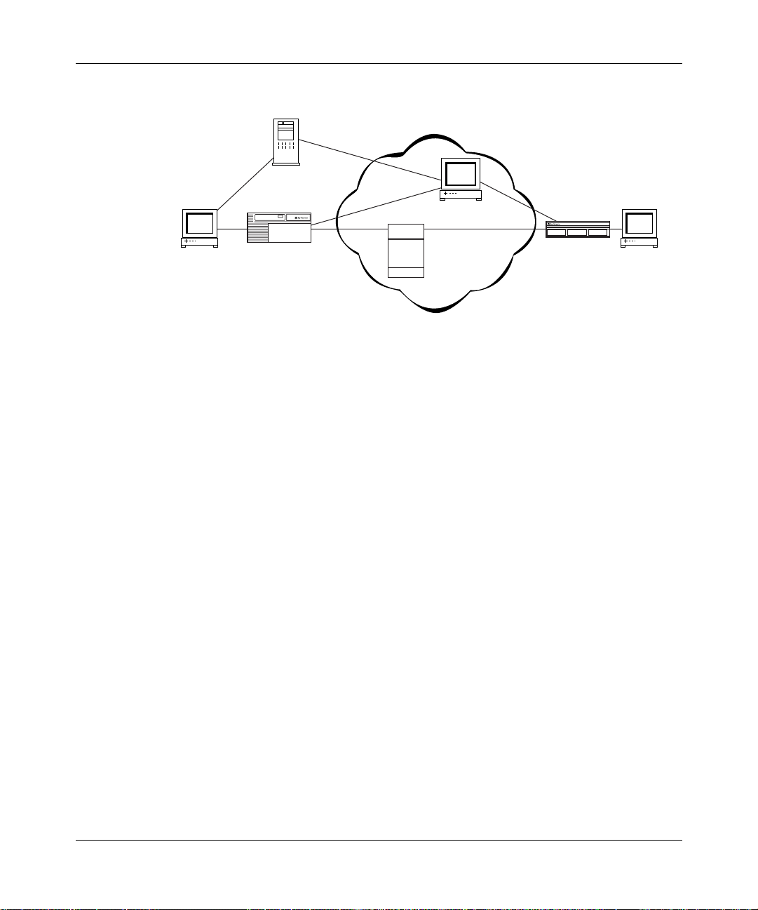
Figure 1-1
and a bandwidth broker. If you manually configure filters, the bandwidth broker
and server manager would not be included.
308620-14.00 Rev 00
The core network device, which is typically a high-performance router,
resides in the ISP or enterprise network. It routes data along the appropriate
path through the network. This router cannot classify packets itself.
The server manager, which resides outside the network, sets up video
conferences. The server manager s omet imes ac ts as the intermediar y bet ween
the host and the bandwidth broker, passing on the host’s requests to the
bandwidth broker. The server manager is not a requi red par t of a d if ferent iated
services network.
shows a differentiated services network tha t i ncl udes a server manager
1-3
Page 22
Configuring Differentiated Services
Server manager
ISP or enterprise network
Bandwidth broker/
policy server
Host
BLN
Highperformance
router
Figure 1-1. Differentiated Services Network
Communicating with the Bandwidth Broker
If your differentiated services network uses a bandwidth broker, the router uses
the COPS protocol to communicate with t he bandwidth broker. COPS enables the
exchange of policy information between the bandwidth broker and its clients.
ASN
Host
DFS0001A
1-4
The router is the COPS client. The COPS client uses the Transmission Control
Protocol (TCP) to communicate with the bandwidth broker. The COPS client can
connect to only one server at a time, choosing the server from list of servers that
you define.
When the router requests a f ilt er from the band width brok er , the bandwidth brok er
responds with its own request to perform one or more of the following actions:
• Install a new filter.
• Update an existing filter.
• Disable or enable an existing filter.
• Delete an existing filter.
For each request, the differentiated services application on the router takes the
necessary action and then sends an acknowledgment back to the bandwidth
broker. Note that the bandwidth broker can also send unsolicited requests.
308620-14.00 Rev 00
Page 23
Differentiated Services Overview
If an interface on the router becomes inactive or terminates, the differentiated
services application deletes all filters from that interface. After the interface
recover s, the r outer nee ds to r equest t he f ilter s from the bandwi dth brok er a gain. If
the connection to the bandwidth broker is temporarily lost, the COPS client
software atte mpts to recon nect to the s erv er. In this case, the router does not delet e
the filters.
The bandwidth brok er a ssigns an I D t o ea ch f i lter b efore inst alli ng it on the rout er.
The bandwidth broker can then change an installed filter based on that ID. If the
bandwidth broker requests an update or removal of a nonexistent filter, the router
ignores the request and sends an error message to the bandwidth broker. You can
view the filters installed by the bandwidth broker using the router’s traffic filters
feature, but you cannot modify them.
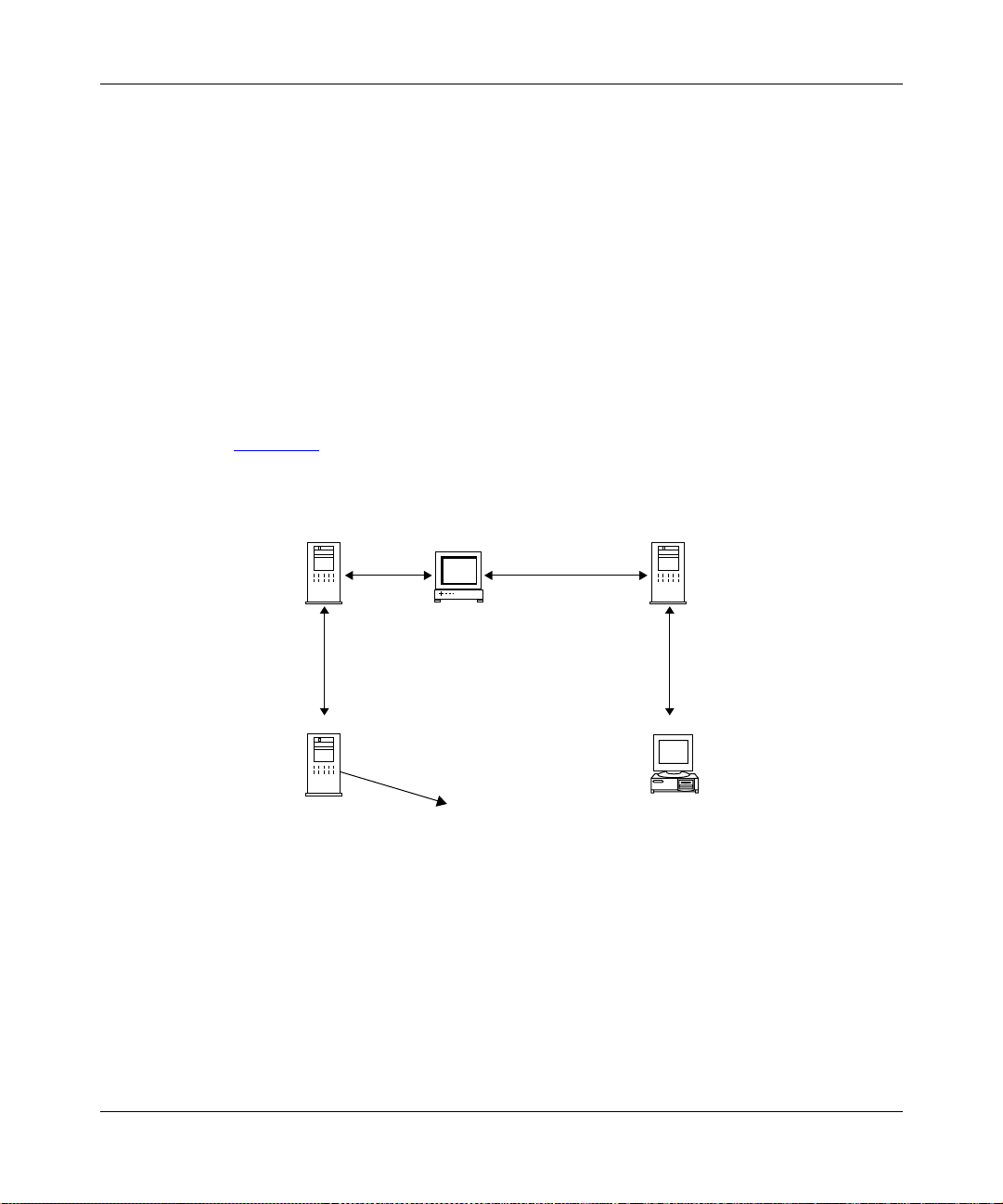
Figure 1-2
Policy server/COPS server GUI
shows the Nortel Networks bandwidth broker architecture.
Application server
Server manager
LDAP
LDAP server
with policy
database
Bandwidth broker PC using
TCP connection
to the router
LDAP
Policy information
is placed in
the database
Web server
PC
Windows NT
DFS0004A
Figure 1-2. Architecture of the Bandwidth Broker
308620-14.00 Rev 00
1-5
Page 24

Configuring Differentiated Services
Marking Packets for Specific Services
A packet’s assigned level of service determines whether it receives preferential
treatment as it travels through the network. The DS field has a specific value that
determines the service.
If the router communicates with a bandwidth broker, the process of installing
filters and marking packets is as follows:
1.
The edge router contacts the bandwidth broker with a configuration request.
This happens automatically as part of the router’s normal differentiated
services activity for each differentiated services interface.
2.
The bandwidth broker responds by downloading a set of trigger and flow
filters from its database to the edge router.
3.
When a packet ar rives at a router’s differentiated services interface, the router
checks its trigger filter and fl ow filt ers, i f an y are ins tall ed, to se e if t he pack e t
matches either f ilte r’s criteria. If the pack et matches the t rigger f il ter’s criteria,
the router sends a message to the bandwidth broker. (For the purposes of this
explanation, we will assume that the packet did not match any previously
installed flow filter.)
1-6
4.
After the bandwidth broker receives a message from the router, it responds,
possibly with its own request to install additional filters.
The router may or may not accept the additional filters because it may have a
limit on the number of filters it can handle, or the filter is misconfigured with
an action that is unknown to the router. If the bandwidth broker does install
additional f ilters, the y are added t o the fil ter table of the diff erentiate d services
interface.
5.
Packets that arrive on that interface that match the flow filter criteria are
marked by the differentiated services application with a DS-field pattern
specified by t he f ilt er. The value in the DS f ield d etermi nes whethe r the pac ket
is sent to a high-priority data queue for preferential treatment. This is how
each packet gets marked or “differen tiated” for a specific type of service.
6.
After a packet is marked, it is sent to the core network device where,
depending on the marking, the packet receives preferential treatment as it is
routed through the network and on to the destination host.
Figure 1-3
shows the Nortel Networks differentiated services architecture and
how the router marks a packet.
308620-14.00 Rev 00
Page 25
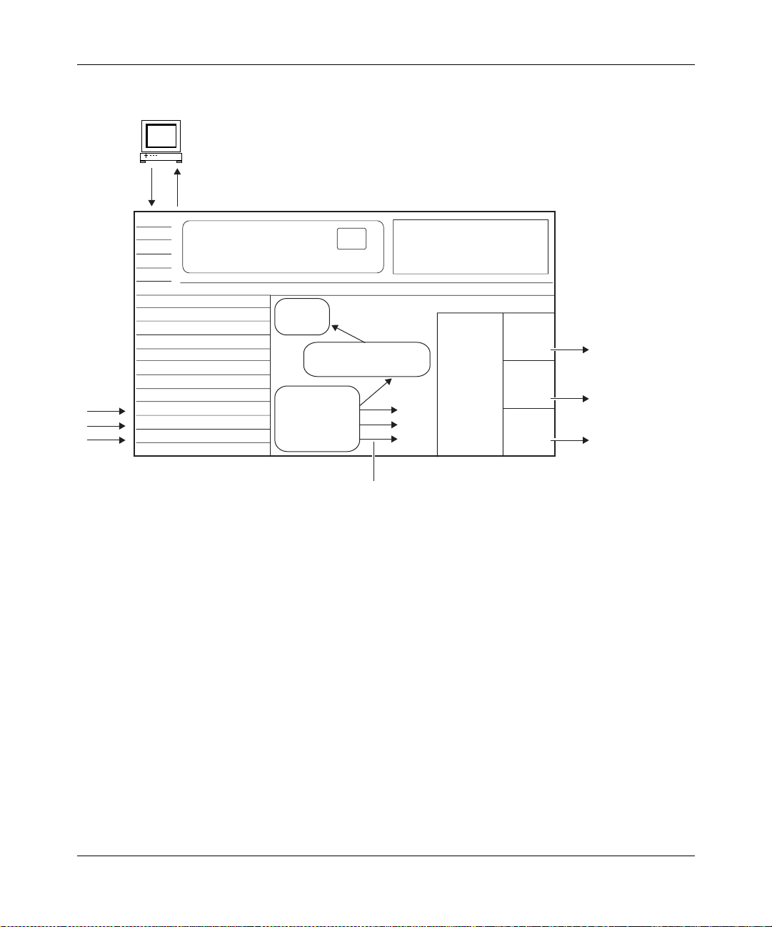
Bandwidth broker/policy server
4/5
COPS client
communicates with the
TCP
connection
6
3
bandwidth broker
Differentiated Services Overview
1
Inbound
data
COPS
client
Differentiated services
application
Classification,
policing, and
marking
mechanism
1. Router receives data.
2. There is a trigger filter match and the differentiated services application is notified.
3. Router sends message to bandwidth broker, which includes the trigger filter ID
and part of the original data packet.
4. Bandwidth broker associates traffic with a level of service. The dataflow
passes policy admission control.
5. Bandwidth broker associates the level of service with bandwidth resources.
The dataflow passes bandwidth admission control.
6. The bandwidth broker installs a flow filter on the router.
2
Flows with the
DS field marked go to
protocol prioritization
Protocol
prioritization
by mark in
DS field
High
queue
Medium
queue
Low
queue
Premium
marked
flows
Tiered
marked
flows
Unmarked
flows
(best effort)
DFS0005A
Figure 1-3. Nortel Networks Differentiated Services Architecture
308620-14.00 Rev 00
1-7
Page 26
Configuring Differentiated Services
URL Filters
The router can filter and mark Hypertext Transfer Protocol (HTTP) traffic based
on uniform resource locator (URL) strings. For the router to use an URL filter,
whether it is installed by the bandwidth broker or configured manually, it must
contain the URL string and optionally, any of the following information:
• Source IP address
• Destination IP address
• Destination port (the default port is 80)
Although only the URL string is required, for efficient data transmission, it is
useful to also include one of these other filter criteria.
After the trigger and flow filters are configured on the router, the router can mark
inbound HTTP traffic for transmission through the network. If the router receives
data that matches a URL filter, the router installs another f il ter, called the dynamic
filter, on the next-hop interface, which is an interface on this same router. This
filter is available for the duration of the HTTP session. This dynamic filter is
deleted if there is no data a cti vity du ring th e time peri od specif ie d by the URL idle
out timer. The original URL filter remains installed on the router.
1-8
For more information about the URL idle out timer, see the URL Idle Out Timer
parameter description on page A-4.
Note:
Even if you configure URL filters manually (static configuration), the
differentiated services application uses COPS to install the dynamic filter.
URL filters are the only filters that create these dynamic filters.
You must configure differentiated services on all possible next-hop interfaces on
the router , or at le ast al l ne xt-h op in terf ace s where t he HTTP se rv ers mig ht res ide.
Otherwise, the router will not be able to mark the return packets.
308620-14.00 Rev 00
Page 27

Chapter 2
Starting Differentiated Services
The quickest way to configure differentiated services on the router is to enable it
with the default configuration that Nortel Networks software supplies. This
configuration u ses all available default values for the interface and COPS
parameters. You will need to supply values only for parameters that do not have
default values.
This chapter includes the following topics:
Topic Page
Planning for a Differentiated Services Network 2-1
Starting the Site Manager Configuration Tool 2-2
Preparing a Configuration File 2-2
Enabling Differentiated Services 2-3
Choosing A Filter Mechanism 2-3
What To Do Next 2-8
Planning for a Differentiated Services Network
This guide primarily explains how to configure a Nortel Networks router as a
differentiated services edge device.
For the router to successfully operate in a differentiated services network, you
must obtain the following information prior to configuring it:
• The IP address of the bandwidth broker.
• The client IP Address and ID of the router. Provide this information to the
administrator configuring the bandwidth broker.
308620-14.00 Rev 00
2-1
Page 28

Configuring Differentiated Services
Starting the Site Manager Configuration Tool
Before configuring differentiated services, see Configuring and Managing
Routers with Site Manager for instructions on how to use the Configuration
Manager for config uration task s. This guide also desc ribes genera lly ho w to create
and modify a configuration.
Preparing a Configuration File
Before starting differentiated services, you must create and save a configuration
file with at l ea st o ne I P interface. The phy si cal interface can b e any LAN port, for
example, Et hernet or token ring.
For information about creating a configuration file, see Quick-Starting Routers.
To add differentiated services to a configuration file, first open the file by
completing the following tasks:
Site Manager Procedure
2-2
You do this System responds
1. In the main Site Manager window, choose
.
Tools
2. Choose
3. Choose
Dynamic
4. Select the file and click on OK. You return to the Configuration Manager
Configuration Manager
Local File, Remote File, or
.
. The Configuration Manager window
The Tools menu opens.
opens.
Site Manager prompts you for the
configuration file you want to open.
window, which displays the router slots
and their associated modules.
308620-14.00 Rev 00
Page 29

Enabling Differentiated Servic es
To enable a differentiated services interface, complete the following tasks:
Site Manager Procedure
You do this System responds
Starting Differentiated Services
1. In the Configuration Manager window,
click on an IP interface connector.
2. Accept the default circuit name or enter a
new name, then click on OK.
3. Scroll through the list of protocols, and
choose
4. Enter the router’s IP address in the
Address
Configuring IP, ARP, RIP, and OSPF
Services
5. Click on
DiffServ
for a parameter descriptio n.
Done
, then click on OK.
field, then click on OK. See
. You return to the Configuration Manager
Choosing A Filter Mechanism
In addition to enabling a differentiated services interface, you must select a
mechanism for installing filters on the router. The router uses filters to determine
which packets it should mark for special treatment through the network. You can
either enable the COPS protocol or manually configure filters.
Note:
The router does not allow IP traffic filters on a differentiated services
interface. If you add differentiated services to an interface that already has IP
traffic filters configured, the router will remove them.
IP
The Add Circuit window opens.
The Select Protocols window opens.
The IP Configuration window opens.
The DiffServ Interfac e List windo w opens .
The interface is now enabled.
window.
Go to one of the following sections to choose a filter mechanism:
• Enabling COPS on page 2-4
• Enabling Static Filters on page 2-5
308620-14.00 Rev 00
2-3
Page 30

Configuring Differentiated Services
Enabling COPS
If the router is receiving filters from a bandwidth broker, you need to enable
COPS so the router can communicate with the bandwidth broker.
To enable COPS, complete the following tasks:
You do this System responds
Site Manager Procedure
1. In the DiffServ Interface List window, set
the
Config Type
Click on
description on page A-4.
2. Click on OK. You return to the DiffServ Interface List
3. Click on
4. Click on OK. You return to the DiffServ Interface List
5. Click on
6. Set the following parameters:
• Client IP Address
• Client ID
Click on
descriptions beginning on page A-8.
7. Click on OK. You return to the DiffServ Interface List
8. Click on
9. Click on
10. Set the
Help
page A-16.
11. Click on OK. You return to the COPS Server List
12. Click on
13. Click on
Help
Apply
COPS Global
Help
COPS Servers
Add
IP Address
or see the parameter description on
Done
Done
parameter to
or see the parameter
. A message prompts:
. The Edit COPS Global Parameters
or see the parameter
. The COPS Server Record window opens.
parameter. Click on
. You return to the DiffServ Interface List.
. You return to the Configuration Manager
COPS
Site Manager displays a message
.
informing you t hat the stati c filters will be
deleted and asks if you want to continue.
window.
Static filters
will be deleted. Do you want to
continue?
window.
window opens.
window.
The COPS Server List window opens.
window, with the server entry listed.
window.
2-4
308620-14.00 Rev 00
Page 31

Enabling Static Filters
If your network does not use a bandwidth broker, you need to manually configure
filters on the router.
When you create traffic filters, it is important to understand the difference
between a t raffic filter template and an actual traffic filter. A filter template is a
reusable, predefined specification for a traffic filter. You create an actual traffic
filter when you apply a filter template to a configured router interface. You can
apply a single template to as many interfaces as you want.
Each template must contain filter criteria and filter actions (log, drop, accept, set
DS field, set DS police). The actions are performed on the filtered packets.
Note:
Log is the only action that you can combine with other actions. For
example, you cannot combine Set DS Field and Set DS Police for one filter.
Creating a Filter Template
Starting Differentiated Services
To configure a diffe renti ated s er vices f ilt er t empla te, co mp lete the fo ll o wi ng ta sks:
You do this System responds
1. In the Configuration Manager window,
2. Choose IP. The IP menu opens.
3. Choose
4. Choose
5. Select the interface you want to modify,
6. Click on
7. Click on
8. Enter a name for the template in t he
308620-14.00 Rev 00
choose
and click on
Name
Protocols
DiffServ
Interfaces
Template
Create
field.
Site Manager Procedure
The Protocols menu opens.
.
. The DiffServ menu opens.
. The DiffServ Interface Lis t win dow opens.
The DiffServ Static Filters window opens.
Traffic Filt
. The Create DiffServ Template window
.
. The Filter Template Management win dow
opens.
opens.
Filter
(continued)
2-5
Page 32

Configuring Differentiated Services
Site Manager Procedure
You do this System responds
9. Choose
10.Choose
11.Add one or more filter criteria.
12.Choose
13.Choose
14.To select the DS field as the filter action,
choose
for the DS Field, 00000000 to 11111111.
See “DS Field” on page A-18 for more
information.
15.To select the DiffServ Police as the filter
action, choose
set the following parameters:
• Token Bucket Rate (Kbps)
• Token Bucket Size (Bits)
• Inprofile Marking
• Out of Profile Marking
Click on
descriptions beginning on page A-20.
Accept the default values for the other
parameters.
16. Click on
17. Click on
18. Click on
19.Apply the filter template according to the
instructions in the next table.
Criteria
Add
Action
Add
DiffServ Set Field
Help
Save
OK.
Done
. The Criteria menu op ens.
. The Add menu opens.
. The Action menu opens.
. The Add menu opens.
and set a value
DiffServ Set Police
or see the parameter
. You return to the Create DiffServ
. You return to the DiffServ Static Filters
and
(continued)
Template window.
You return to the Filter Template
Management window.
window.
2-6
308620-14.00 Rev 00
Page 33

Starting Differentiated Services
Applying the Template to a Filter
After you create your differentiated services filter template, you need to create a
filter by applying the template to a differentiated ser vices interface.
To apply a filter templ ate, complete th e following tasks:
Site Manager Procedure
You do this System responds
1. In the DiffServ Static Filters window, click
on
2. Enter a name for the filter in the
Name
3. Select the diff e ren tiat ed s ervices interface
that should use this filter in the Interfaces
list.
4. Select a template in the Templates list.
5. Click on
6. Click on
Configuration Manager window.
Create
field.
.
OK
until you return to the
Done
Filter
The Create Filter window opens.
You return to the DiffServ Static Filters
window. Site Manager displays the filter
name and its interface in the scroll list.
Configuring Filters for HTTP Packets
To modify a filter to include URLs, complete the following tasks:
Site Manager Procedure
You do this System responds
1. See “Creating a Filter Template
page 2-5
the table.
2. Click on
3. Choose
4. Choose
5. Choose
and follow steps 1 through 5 in
. The Edit DiffServ Filters window opens.
Edit
Criteria
Add
Add URL
. The Criteria menu op ens.
. The Add menu opens.
. The A dd URL window opens.
” on
(continued)
308620-14.00 Rev 00
2-7
Page 34

Configuring Differentiated Services
You do this System responds
6. Set the
see the param eter descr iption on
page A-23.
7. Click on
8. Click on OK. You return to the DiffServ Static Filters
9. Click on
Configuration Manager window.
You must always associat e a f ilter criteri a with a f ilte r action. Thi s ensures th at the
router uses the URL criterion with the appropriate differentiated services action,
for example, Set DS Field, to determine how to mark packets.
For detailed inf o r mation about creating filters, see Configuring Traffic Filters and
Protocol Prioritization.
What To Do Next
parameter. Click on
URL
OK.
until you return to the
Done
Site Manager Procedure
or
Help
You return to the Edit DiffServ Filters
window.
window.
(continued)
2-8
Now that you have completed the steps in this chapter, differentiated services
should be operating on at least one interface. To customize the differentiated
services configuration, go to Chapte r 3, “Customizing Differentiated Servic es.”
308620-14.00 Rev 00
Page 35

Chapter 3
Customizing Differentiated Services
When you enable differentiated services, default values are in effect for all
parameters. Depending on your network requirements, you may want to change
these values.
This chapter describes how to customize your differentiated services
configuration and includes the following topics:
Topic Page
Adding a Differentiated Services Interface 3-2
Modifying a Differentiated Services Interface 3-3
Disabling and Reenabling Differentiated Services Interfaces 3-4
Deleting Differentiated Services Interfaces 3-5
Adding COPS Servers 3-6
Modifying COPS Global Parameters 3-7
Modifying the COPS Server Record 3-8
Disabling and Reenabling a COPS Server 3-11
Deleting a COPS Server 3-11
Disabling and Reenabling COPS on the Router 3-12
Deleting COPS from the Router 3-12
Modifying Traffic Filters 3-13
308620-14.00 Rev 00
3-1
Page 36

Configuring Differentiated Services
Adding a Differentiated Services Interface
To add a differentiated services interface, complete the following tasks:
Site Manager Procedure
You do this System responds
1. In the Configuration Manager window,
choose
2. Choose IP. The IP menu opens.
3. Choose
4. Choose
5. Click on
6. Click on
7. Select an IP interface from the list, then
click on OK.
8. Click on OK. You return to the DiffServ Interface List
9. Click on
Protocols
DiffServ
Interfaces
Add
Values
Done
.
. The DiffServ menu opens.
. The DiffServ Interface Lis t win dow opens.
. The DiffServ Interface Record window
. The Values Selection window opens.
. You return to the Configuration Manager
The Protocols menu opens.
opens.
Site Manager enters this address for the
IP Address parameter.
window.
window.
3-2
308620-14.00 Rev 00
Page 37

Customizing Differentiated Services
Modifying a Differentiated Ser vices Interfac e
You can modify the configuration type of a differentiated services interface,
specify which debug messages for an interface are stored in the router’s events
log, and specify an idle timer for URL fil t ers.
To modify a differentiated services interface, complete the following tasks:
Site Manager Procedure
You do this System responds
1. In the Configuration Manager window,
choose
2. Choose IP. The IP menu opens.
3. Choose
4. Choose
5. Select the interface you want to modify.
6. Set the following parameters:
• Config Type
• Debug Log Mask (hex)
• URL Idle Out Timer
Click on
descriptions beginning on page A-3.
7. Click on
Protocols
DiffServ
Interfaces
Help
Done
.
. The DiffServ menu opens.
. The DiffServ Interface Lis t win dow opens.
or see the parameter
. You return to the Configuration Manager
The Protocols menu opens.
window.
308620-14.00 Rev 00
3-3
Page 38

Configuring Differentiated Services
Disabling and Reena bling Differentiated Services Int erfaces
After you create a differentiated services interface, by default it is enabled. You
can disable and reenable a single interface or all interfaces at any time.
Disabling and Reenabling a Single Interface
To disable or reenable a single interface, complete the following tasks:
Site Manager Procedure
You do this System responds
1. In the Configuration Manager window,
choose
2. Choose IP. The IP menu opens.
3. Choose
4. Choose
5. Select the interface you want to disable or
reenable.
6. Set the
or see the parameter description on
page A-3.
7. Click on
Protocols
DiffServ
Interfaces
Enable
Done
.
. The DiffServ menu opens.
. The DiffServ Interface Lis t win dow opens.
parameter. Click on
. You return to the Configuration Manager
Help
Disabling and Reenabling All Interfaces
To globally disable or reenable differentiated services interfaces, complete the
following tasks:
Site Manager Procedure
You do this System responds
The Protocols menu opens.
window.
3-4
1. In the Configuration Manager window,
choose
2. Choose IP. The IP menu opens.
Protocols
.
The Protocols menu opens.
(continued)
308620-14.00 Rev 00
Page 39

Customizing Differentiated Services
Site Manager Procedure
You do this System responds
3. Choose
4. Choose
5. Set the
or see the parameter description on
page A-6.
6. Click on
DiffServ
Global
Enable
Done
. The DiffServ menu opens.
. The Edit DiffServ Global Parameters
parameter. Click on
. You return to the Configuration Manager
Help
(continued)
window opens.
window.
Deleting Differentiated Services Interfaces
You can delete a single interface or all interfaces from the router.
Deleting a Single Interface
To delete a single interface, complete the following tasks:
Site Manager Procedure
You do this System responds
1. In the Configuration Manager window,
2. Choose IP. The IP menu opens.
3. Choose
4. Choose
5. Select the interface you want to disable or
6. Click on
308620-14.00 Rev 00
choose
reenable, and click on
Protocols
DiffServ
Interfaces
Done
.
. The DiffServ menu opens.
. The DiffServ Interface Lis t win dow opens.
. You return to the Configuration Manager
Delete
The Protocols menu opens.
Site Manager removes the interface from
.
the list.
window.
3-5
Page 40

Configuring Differentiated Services
Deleting All Interfaces
To globally delete differentiated services interfaces, complete the following tasks:
You do this System responds
Site Manager Procedure
1. In the Configuration Manager window,
choose
2. Choose IP. The IP menu opens.
3. Choose
4. Choose
5. Click on OK. You return to the Configuration Manager
Protocols
DiffServ
Delete
Adding COPS Servers
To add COPS servers that the router can communicate with, complete the
following tasks:
You do this System responds
1. In the Configuration Manager window,
choose
2. Choose
3. Choose
4. Choose
5. Click on Add. The COPS Server Record window opens .
6. Set the
Help
page A-16.
Protocols
Global Protocols
COPS Client
COPS Servers
IP Address
or see the parameter description on
The Protocols menu opens.
.
. The DiffServ menu opens.
. A confirmation windo w prompts:
REALLY want to delete
DiffServ?
window.
Site Manager Procedure
The Protocols menu opens.
.
. The Global Protocols menu opens.
. The COPS Client menu opens.
. The COPS Server List window opens
parameter. Click on
(continued)
Do you
3-6
308620-14.00 Rev 00
Page 41

Customizing Differentiated Services
Site Manager Procedure
You do this System responds
7. Click on OK. You return to the COPS Server List
8. Click on
. You return to the Configuration Manager
Done
Modifying COPS Global Parameters
In most cases, you do not ne ed t o modi fy t he s olo slot mask, the COPS client’s IP
address, or the client ID after you initially configure them. However, you may
modify these parameters.
To modify the client’s address and ID, complete the following tasks:
Site Manager Procedure
You do this System responds
1. In the Configuration Manager window,
choose
2. Choose
3. Choose
4. Choose
5. Set the following parameters:
• Solo Slot Mask
• Client IP Address
• Client ID
Click on
descriptions beginning on page A-8.
6. Click on OK. You return to the Configuration Manager
Protocols
Global Protocols
COPS Client
COPS Global
Help
.
. The Global Protocols menu opens.
. The COPS Client menu opens.
. The Edit COPS Global Parameters
or see the parameter
(continued)
window. Site Manager adds the new
server to the server list.
window.
The Protocols menu opens.
window opens.
window.
308620-14.00 Rev 00
3-7
Page 42

Configuring Differentiated Services
Modifying the COPS Server Record
The following sections describe how to modify the COPS server record.
Prioritizing COPS Servers
You can prioritize the available COPS servers so that the router tries connecting to
one server before trying another. The router can connect to only one server at a
time.
To assign a priority number to each server, complete the following tasks:
Site Manager Procedure
You do this System responds
1. In the Configuration Manager window,
choose
2. Choose
3. Choose
4. Choose
5. Set the
or see the parameter description on
page A-10.
6. Click on
7. Click on
Protocols
Global Protocols
COPS Client
COPS Servers
Priority
Apply
Done
.
. The COPS Client menu opens.
. The COPS Server List window opens.
parameter. Click on
.
. You return to the Configuration Manager
Modifying the COPS Connection
The connection to the COPS server is established at two different levels, the
COPS layer and the TCP layer. The COPS application on the router is a TCP
client.
At the COPS level, you can customize how the router connects to a COPS server,
for example, defining how often the router retries a connection and how long the
router keeps the connection active.
The Protocols menu opens.
. The Global Protocols menu opens.
Help
window.
3-8
308620-14.00 Rev 00
Page 43

Customizing Differentiated Services
To customize how the router connects to a COPS server, complete the following
tasks:
Site Manager Procedure
You do this System responds
1. In the Configuration Manager window,
choose
2. Choose
3. Choose
4. Choose
5. Set the following parameters:
• Connection Retry Period
• Connection Retry Count
• KeepAlive Time Period
• Report Time Period
Click on
descriptions beginning on page A-10.
6. Click on
7. Click on
Protocols
Global Protocols
COPS Client
COPS Servers
Help
Apply
Done
.
. The Global Protocols menu opens.
. The COPS Client menu opens.
. The COPS Server List window opens.
or see the parameter
.
. You return to the Configuration Manager
The Protocols menu opens.
window.
Maintaining the TCP Connection to the Server
The router communicates to the COPS server across a TCP connection. To keep
the connection established, even when there is no data being transmitted, you can
configure keepalive timers and retry counts to maintain the connection.
To modify the keepalive parameters that maintain the TCP connection, complete
the following tasks:
You do this System responds
1. In the Configuration Manager window,
2. Choose
3. Choose
308620-14.00 Rev 00
choose
Protocols
Global Protocols
COPS Client
.
. The COPS Client menu opens.
Site Manager Procedure
The Protocols menu opens.
. The Global Protocols menu opens.
(continued)
3-9
Page 44

Configuring Differentiated Services
Site Manager Procedure
You do this System responds
4. Choose
5. Set the following parameters:
• TCP KeepAlive Interval
• TCP KeepAlive RTO
• TCP KeepAlive Max Retry Cnt
Click on
descriptions beginning on page A-10.
6. Click on
7. Click on
COPS Servers
or see the parameter
Help
.
Apply
. You return to the Configuration Manager
Done
. The COPS Server List window opens.
Changing the Remote TCP Port
If the bandwidth broker application operates on a different port than the default,
which is the defined COPS standard, you can specify a different port. In most
cases, however, you can use the default port.
To modify the remote TCP port, complete the following tasks:
(continued)
window.
3-10
Site Manager Procedure
You do this System responds
1. In the Configuration Manager window,
choose
2. Choose
3. Choose
4. Choose
5. Set the
Click on
descriptions beginning on page A-14.
6. Click on
7. Click on
Protocols
Global Protocols
COPS Client
COPS Servers
Remote TCP Port
Help
Apply
Done
.
. The Global Protocols menu opens.
. The COPS Client menu opens.
. The COPS Server List window opens.
parameter.
or see the parameter
.
. You return to the Configuration Manager
The Protocols menu opens.
window.
308620-14.00 Rev 00
Page 45

Customizing Differentiated Services
Disabling and Reenabling a COPS Serve r
To disable and reenable a single COPS server, complete the following tasks:
Site Manager Procedure
You do this System responds
1. In the Configuration Manager window,
choose
2. Choose
3. Choose
4. Choose
5. Select the server entry you want to disable
or reenable.
6. Set the
or see the parameter description on
page A-10.
7. Click on
Protocols
Global Protocols
COPS Client
COPS Servers
Enable
parameter. Click on
. You return to the Configuration Manager
Done
Deleting a COPS Server
To delete a single server entry from the server list, c omplete the following tasks:
You do this System responds
1. In the Configuration Manager window,
choose
2. Choose
3. Choose
4. Choose
5. Select the server entry you w ant to de lete ,
then click on
6. Click on
Protocols
Global Protocols
COPS Client
COPS Servers
Delete
. You return to the Configuration Manager
Done
The Protocols menu opens.
.
. The Global Protocols menu opens.
. The COPS Client menu opens.
. The COPS Server List window opens.
Help
window.
Site Manager Procedure
The Protocols menu opens.
.
. The Global Protocols menu opens.
. The COPS Client menu opens.
. The COPS Server List window opens.
Site Manager removes the entry.
.
window.
308620-14.00 Rev 00
3-11
Page 46

Configuring Differentiated Services
Disabling and Reenabling COPS on the Router
To disable and reenable all COPS servers, complete the following tasks:
Site Manager Procedure
You do this System responds
1. In the Configuration Manager window,
choose
2. Choose
3. Choose
4. Choose
5. Set the
or see the parameter description on
page A-7.
6. Click on OK. You return to the Configuration Manager
Protocols
Global Protocols
COPS Client
COPS Global
Enable
.
. The Global Protocols menu opens.
. The COPS Client menu opens.
. The Edit COPS Global Parameters
parameter. Click on
Deleting COPS from the Router
To delete COPS functionality from the router, complete the following tasks:
Site Manager Procedure
You do this System responds
1. In the Configuration Manager window,
choose
2. Choose
3. Choose
4. Choose
5. Click on OK. You return to the Configuration Manager
Protocols
Global Protocols
COPS Client
COPS Delete
.
. The Global Protocols menu opens.
. The COPS Client menu opens.
. A confirmation windo w prompts:
Help
The Protocols menu opens.
window opens.
window.
The Protocols menu opens.
Do you
REALLY want to delete COPS?
window.
3-12
308620-14.00 Rev 00
Page 47

Modifying Traffic Filters
If you selected static for an interface’s configuration type, you configured traffic
filters because filters are not downloaded from a bandwidth broker.
Note that unlike standard IP traffic filters, only the following actions are allowed
for differentiated services traffic filters:
• Log -- For every packet that matches the filter entry, the router enters a
message in the Events log. You can specify this action together with other
actions.
• Drop -- The router does not route any packet that matches the filter criteria.
• Accept -- The router forwards a packet without marking it.
• DiffServ Set Field -- The router sets the DS byte in the IP header for all
packets that match the filter criteria.
• DiffServ Set Police -- The router monitors the packet flow and determines if
that packet is in or out of the profile. If the packet fits the profile, the router
sets the DS byte.
Customizing Differentiated Services
Another feature unique to differentiated services filters is that you can use URLs
as filter criteria, which enables the router to mark HTTP packets.
DS Field and DS Police Traffic Filters
These procedures assu me t hat you have crea te d a filter templ ate and appli ed i t to a
filter.
To modify a filter that includes DS Field or DS Police action, complete the
following tasks:
Site Manager Procedure
You do this System responds
1. In the Configuration Manager window,
2. Choose IP. The IP menu opens.
3. Choose
308620-14.00 Rev 00
choose
Protocols
DiffServ
.
. The DiffServ menu opens.
The Protocols menu opens.
(continued)
3-13
Page 48

Configuring Differentiated Services
Site Manager Procedure
You do this System responds
4. Choose
5. Select the interface you want to modify,
and click on
6. Select the filter you want to edit and click
on
7. To change the DS field entry, choose
Action > Edit DS Field
8. To modify the DS Police action, choose
Action > Edit DS Police
following parameters:
• Token Bucket Rate (Kbps)
• Token Bucket Size (Bits)
• MIN Policed (Bytes)
• MAX Policed (Bytes)
• Inprofile Marking
• Inprofile Behavior
• Out of Profile Marking
• Out of Profile Behavior
Click on Help or see the parameter
descriptions beginning on page A-20.
9. Click on
10. Click on OK. You return to the DiffServ Static Filters
11. Click on
Configuration Manager window.
Edit
Interfaces
.
Save.
Done
. The DiffServ Interface Lis t win dow opens.
Traffic Filt
until you return to the
.
.
and set the
(continued)
The DiffServ Static Filters window opens.
The Edit DiffServ Filters window opens.
The DS Field window opens.
You return to the Edit DiffServ Filters
window.
window.
3-14
308620-14.00 Rev 00
Page 49

URL Filters
Customizing Differentiated Services
These procedures assu me t hat you have crea te d a filter templ ate and appli ed i t to a
filter.
To modify a filter that includes a URL as a criterion, complete the following tasks:
Site Manager Procedure
You do this System responds
1. In the Configuration Manager window,
choose
2. Choose IP. The IP menu opens.
3. Choose
4. Choose
5. Select the interface you want to modify,
and click on
6. Select the filter you want to edit and click
on
7. Select a URL and click on
8. Make any modifications, then click on OK. You return to the Edit DiffServ Filters
9. Click on OK. You return to the DiffServ Static Filters
10. Click on
Configuration Manager window.
Edit
Protocols
DiffServ
Interfaces
.
Done
.
. The DiffServ menu opens.
. The DiffServ Interface Lis t win dow opens.
Traffic Filt
until you return to the
.
. The Edit URL window opens.
Modify
The Protocols menu opens.
The DiffServ Static Filters window opens.
The Edit DiffServ Filters window opens.
window.
window.
For general information about how to create traffic filters, see Conf i guri ng Traffic
Filters and Protocol Prioritization.
308620-14.00 Rev 00
3-15
Page 50

Page 51

Appendix A
Site Manager Pa rameters
These topi cs define differentiate d services parameters:
Topic Page
Interface List Parameters A-2
Interface Record Parameter A-5
Differentiated Services Global Parameter A-6
COPS Global Parameters A-7
COPS Server List Parameters A-9
COPS Server Record Parameters A-15
Static Traffic Filter Parameters A-16
For each parameter, this appendix provides the following information:
• Parameter name
• Configuration Manager menu path
• Default setting
• Valid parameter options
• Parameter function
• Instructio ns for setting the parameter
• Management information base (MIB) object ID
308620-14.00 Rev 00
A-1
Page 52

Configuring Differentiated Services
The Technician Interface allows you to modi fy attributes by issuing set and
commit commands with the MIB Object ID. This process is equivalent to
modifying parameters using Site Manager. For more information about using the
Technician Interface to access the MIB, see Using Technician Interface Software.
Caution:
The Technician Interface does not verify attribute values you enter.
Entering an invalid value can corrupt your configuration.
Interface List Parameters
The DiffServ Interface List window (Figure A-1) contains the parameters for the
differe ntiated ser vices inter faces. These parameter s let you enable an interf ace and
determine its configuration type.
A-2
Figure A-1. DiffServ Interface List Window
308620-14.00 Rev 00
Page 53

Site Manager Parameters
Parameter: Enable
Path: Configuration Manager > Protocols > IP > DiffServ > Interfaces
Default: Enabled
Options: Enabled
Function: Enables or disables differentiated ser vices on this interface.
Instructions: After you configure a differentiated ser vices inter fac e, this paramet er is enabl ed
by default . To disable differen tiated serv ices on this i nterfac e without de leting it,
select Disabled.
MIB Object ID: 1.3.6.1.4.1.18.3.5.26.2.1.2
Parameter: Debug Log Mask (hex)
Path: Configuration Manager > Protocols > IP > DiffServ > Interfaces
Default: 0x00000001
Options: Filter Maintenance
Extra Debugging
Function: Specifies which event messages the router should include in the event log.
Instructions: Select one or more event messages that you want to include in the log. To log
events such as when a filter is added, deleted, enabled, or disabled, select Filter
Maintenance. To log when a packet matches a trigger filter criterion and is sent
to the server, select Trigger Events. The other options are for debugging. Site
Manager fills in the appropriate hex value for the options you have chosen.
MIB Object ID: 1.3.6.1.4.1.18.3.5.26.2.1.6
Disabled
|
Interaction w ith COPS | Trigger Events | IP Interaction |
|
308620-14.00 Rev 00
A-3
Page 54

Configuring Differentiated Services
Parameter: Config Type
Path: Configuration Manager > Protocols > IP > DiffServ > Interfaces
Default: Static
Options: Static
COPS
|
Function: Indicates the configuration type for this interface. The configuration type
defines whet her the i nterface uses manually con f i gured f i lter s or filters insta lled
by the bandwidth broker.
Instructions: Select the appropriate configuration type:
Static -- Select this option to manually configure filters. These filters identify
packets for specific data flows and define the actions performed on each packet.
COPS -- Select this option to use the Common Open Policy Server (COPS)
protocol to request flow filters from the bandwidth broker. Using COPS, the
flow f ilters are alr eady a v ailabl e from the bandwidth br oker a nd are do wnl oaded
to the router upon request.
MIB Object ID: 1.3.6.1.4.1.18.3.5.26.2.1.7
Parameter: URL Idle Out Timer
Path: Configuration Manager > Protocols > IP > DiffServ > Interfaces
Default: 120
Options: 1 to 0x7fffffff seconds
Function: Specifies the number of seconds that the router waits before a dynamic URL
filter on the next-hop interface is deleted.
Instructions: Specify a value for the idle out time period.
MIB Object ID: 1.3.6.1.4.1.18.3.5.26.2.1.8
A-4
308620-14.00 Rev 00
Page 55

Interface Record Parameter
The DiffServ Interface Record window (Figure A-2) contains the IP Address
parameter for the differentiated services interfac e. Th is par ameter lets you spec if y
a configured IP address as a differentiated services interface.
Site Manager Parameters
Figure A-2. DiffServ Interface Record Window
Parameter: IP Address
Path: Configuration Manager > Protocols > IP > DiffServ > Interfaces > Add
Default: None
Options: An existing IP address on the router
Function: Identifies a differentiated services interface on the router.
Instructions: Enter the IP address of the differentiated services interface.
MIB Object ID: Not Applicable
308620-14.00 Rev 00
A-5
Page 56

Configuring Differentiated Services
Differentiated Services Global Parameter
The Edit DiffServ Global Parameters window (Figure A-3) contains the Enable
parameter, which l ets you disab le and ree nable all d ifferentiated se rvice inter fa ces
on the router.
Figure A-3. Edit DiffServ Global Parameters Window
Parameter: Enable
Path: Configuration Manager > Protocols > IP > DiffServ > Global
Default: Enabled
Options: Enabled
Function: Disables and reenables all differentiated services interfaces on the router.
Instructions: To disable differentiated services on the router, select Disabled. Otherwise,
accept the default.
MIB Object ID: 1.3.6.1.4.1.18.3.5.26.1.2
A-6
Disabled
|
308620-14.00 Rev 00
Page 57

COPS Global Parameters
The Edit COPS Global P arameters windo w ( Figure A-4) contains the COPS client
parameters. These are global parameters t hat apply to the entire router , not just an
individual interface. These parameters let you customize how the router
communicates with the bandwidth broker.
Site Manager Parameters
Figure A-4. Edit COPS Global Parameters Window
Parameter: Enable
Path: Configuration Manager > Protocols > Global Protocols > COPS Client >
COPS Global
Default: Enabled
Options: Enabled
Function: Enables and disables COPS on the router.
Instructions: If you selected COPS as the configuration type, this parameter is automatically
set to Enabled. To disable COPS without deleting it, select Disabled.
MIB Object ID: 1.3.6.1.4.1.18.3.5.25.1.1.2
308620-14.00 Rev 00
Disabled
|
A-7
Page 58

Configuring Differentiated Services
Parameter: Solo Slot Mask
Path: Configuration Manager > Protocols > Global Protocols > COPS Client >
COPS Global
Default: All slots on the router. The number of slots varies by hardware platform.
Options: Hex number representing the slots on the router, up to slot 14.
Function: Specifies the mask for the slot on which the soloist can operate. The most
signific ant bit (MS Bi t ) re presents slot 1, the next most signif ic ant bit represents
slot 2 and so on, up to slot 14.
Instructions: For most cases, accept the default. If you want to change how the router
manages its slot resources, change the slot mask by entering a hex value that
specifies the slots for the COPS soloist.
MIB Object ID: 1.3.6.1.4.1.18.3.5.25.1.1.6
Parameter: Client IP Address
Path: Configuration Manager > Protocols > Global Protocols > COPS Client >
COPS Global
Default: None
Options: An IP address of a router interface
Function: Specifies the IP interface address of the COPS client, that is, the router. COPS
uses this address to communicate with the bandwidth broker.
Instructions: Enter the IP address of the router as the COPS client.
MIB Object ID: 1.3.6.1.4.1.18.3.5.25.1.1.8
Parameter: Client ID
Path: Configuration Manager > Protocols > Global Protocols > COPS Client >
COPS Global
Default: None
Options: Any alphanumeric string
Function: Identifies the router to the COPS server by assigning it a unique ID.
Instructions: Specify an ID for the router as the COPS client.
MIB Object ID: 1.3.6.1.4.1.18.3.5.25.1.1.9
A-8
308620-14.00 Rev 00
Page 59

COPS Server List Parameters
The COPS Server List windo w (Fi gure A-5) contains the list of COPS servers that
are allowed to install filters on the router.
Site Manager Parameters
Figure A-5. COPS Server List Window
308620-14.00 Rev 00
A-9
Page 60

Configuring Differentiated Services
Parameter: Enable
Path: Configuration Manager > Protocols > Global Protocols > COPS Client >
COPS Servers
Default: Enabled
Options: Enabled
Disabled
|
Function: Enables and disables a COPS server.
Instructions: If you selected COPS as the configuration type, this parameter is automatically
set to Enabled. To disable a COPS serv er wi thout delet ing it from t he ser v er li st,
select Disabled.
MIB Object ID: 1.3.6.1.4.1.18.3.5.25.1.2.1.2
Parameter: Priority
Path: Configuration Manager > Protocols > Global Protocols > COPS Client >
COPS Servers
Default: 1
Options: 1 to 128
Function: Assigns a priority rating to the COPS server. The higher the number, the higher
the priority. For example, a server with a priority of 2 will be the active server
before a server with a priority of 1.
Instructions: Enter a priority value for the server.
MIB Object ID: 1.3.6.1.4.1.18.3.5.25.1.2.1.4
Parameter: Connection Retry Period
Path: Configuration Manager > Protocols > Global Protocols > COPS Client >
COPS Servers
Default: 30
Options: 1 to 65535 seconds
Function: Specifies the time period, in seconds, between connection retry attempts to the
server.
Instructions: Enter a value for the connection retry interval.
MIB Object ID: 1.3.6.1.4.1.18.3.5.25.1.2.1.6
A-10
308620-14.00 Rev 00
Page 61

Site Manager Parameters
Parameter: Connection Retry Count
Path: Configuration Manager > Protocols > Global Protocols > COPS Client >
COPS Servers
Default: 3
Options: 1 to 10
Function: Specifies the number of connection attempts that the router makes before
determining that the server is unreachable.
Instructions: Enter a value for the number of connection retry attempts to the server.
MIB Object ID: 1.3.6.1.4.1.18.3.5.25.1.2.1.7
Parameter: KeepAlive Time Period
Path: Configuration Manager > Protocols > Global Protocols > COPS Client >
COPS Servers
Default: 1
Options: 1 to 65535 seconds
Function: Specifies the time period, in seconds, between the transmission of keepalive
packets to the server.
Instructions: Enter a value for the transmission interval betw een keepalive packets. Note that
the router negotiates this value with the server. If the server replies with a value
that is different from the value you set, the router uses th e server’s value.
MIB Object ID: 1.3.6.1.4.1.18.3.5.25.1.2.1.8
308620-14.00 Rev 00
A-11
Page 62

Configuring Differentiated Services
Parameter: Report Time Period
Path: Configuration Manager > Protocols > Global Protocols > COPS Client >
COPS Servers
Default: 360
Options: 1 to 65535 seconds
Function: Specifies the time period, in seconds, between the transmission of statistics
reports to the server. The statistics reports provide information for each flow
filter.
Instructions: Enter a value for the transmission interval between reports. Note that the router
negotiates this value with the server. If the server replies wi th a value that is
different from the value you set, the router uses the server’s value.
MIB Object ID: 1.3.6.1.4.1.18.3.5.25.1.2.1.9
Parameter: TCP KeepAlive Interval
Path: Configuration Manager > Protocols > Global Protocols > COPS Client >
COPS Servers
Default: 60
Options: 0 to 65535 seconds
Function: Specifies the time period, in seconds, between the transmission of keepalive
packets that the router sends across a TCP connection.
Instructions: Enter a value for the transmission interval between TCP keepalive packets.
Enter a value of 0 to disable this feature.
MIB Object ID: 1.3.6.1.4.1.18.3.5.25.1.2.1.10
A-12
308620-14.00 Rev 00
Page 63

Site Manager Parameters
Parameter: TCP KeepAlive RTO
Path: Configuration Manager > Protocols > Global Protocols > COPS Client >
COPS Servers
Default: 60
Options: 0 to 65535 seconds
Function: Specifies the keepalive retransmit timeout (RTO) period, in seconds. This is the
interva l during whi ch the ro uter s ends unack no wledged keep ali ve pack ets. If the
TCP KeepAlive Interval parameter is set to 0, the router ignores this timer.
If the TCP KeepAlive Interval Timer is set to a nonzero value and this parameter
is set to 0, the router does not send keepalive packets. Either side of the
connection can then end the session after the TCP KeepAlive Interval expires.
Instructions: Enter a value for the retransm it timeout peri od.
MIB Object ID: 1.3.6.1.4.1.18.3.5.25.1.2.1.11
Parameter: TCP KeepAlive Max Retry Cnt
Path: Configuration Manager > Protocols > Global Protocols > COPS Client >
COPS Servers
Default: 4
Options: 0 to 65535
Function: Specifies the number o f unackno wledged keepali v e packe ts retrans mitted bef ore
the TCP session is terminated. If this value is set to 0, the rout er only sends one
keepali ve packet.
Instructions: Enter a number for the maximum number of unackno wled ged keepal i ve pa ckets
the router should send.
MIB Object ID: 1.3.6.1.4.1.18.3.5.25.1.2.1.12
308620-14.00 Rev 00
A-13
Page 64

Configuring Differentiated Services
Parameter: Remote TCP Port
Path: Configuration Manager > Protocols > Global Protocols > COPS Client >
COPS Servers
Default: 3288
Options: 1 to 65535
Function: Specifies the remote TCP port of the COPS server.
Instructions: In most cases, accept the default TCP port, 3288. If the bandwidth broker
application operates on a port that is different from the default, specify a
different port.
MIB Object ID: 1.3.6.1.4.1.18.3.5.25.1.2.1.13
A-14
308620-14.00 Rev 00
Page 65

COPS Server Record Parameters
The COPS Server Record window (FigureA-6) contains the parameters that tell
the router how to communicate with the COPS servers. With the exception of the
IP Address parameter, described on page A-16
the same as those in the COPS Server List window (see Figure A-5
Site Manager Parameters
, the parameters in this window are
on page A-9).
See “COPS Server List Parameters
descriptions.
” beginning on page A-9 for parameter
Figure A-6. COPS Server Record Window
308620-14.00 Rev 00
A-15
Page 66

Configuring Differentiated Services
Parameter: IP Address
Path: Configuration Manager > Protocols > Global Protocols > COPS Client >
COPS Servers > Add
Default: None
Options: A valid IP address
Function: Identifies the COPS server.
Instructions: Enter the IP address of the COPS server.
MIB Object ID: Not applicable
Static Traffic Filter Parameters
When you click on the Traffic Filt button in the DiffServ Interface List window
(see Figure A-1
opens. From this window, you can configure traffic filters.
on page A-2), the DiffServ Static Filters window (Figure A-7)
A-16
Figure A-7. DiffServ Static Filters Window
308620-14.00 Rev 00
Page 67

Site Manager Parameters
When you click on Template in the DiffServ Static Filters window (FigureA-7),
and then click on Create, the Create DiffServ Template window opens
(Figure A-8)
.
Figure A-8. Create DiffServ Template Window
From this window, you can configure filter criteria and actions.
There are many cri te ri a y ou ca n add to a filt er. For more information abo ut filters,
see Configuring Traffic Filters and Protocol Prioritization.
308620-14.00 Rev 00
A-17
Page 68

Configuring Differentiated Services
For the filter criteria, the URL string criterion is unique to differentiated services.
For the filter criteria, you can add the following actions:
•Log
•Drop
• Accept
• Set DS Field
• Set DS Police
Note:
Log is the only action that you can combine with other actions. For
example, you cannot combine Drop and Set DS Field.
DS Field
If you add the action Set DS Field, the DS Field window opens (Figure A-9). The
DS field specifies the marking of the DS field in the IP packet header. The range
can be 00000000 to 11111111, which is 0 to 255 expressed in binary form.
A-18
Figure A-9. DS Field Window
RFC 2474 defines specific guidelines for configuring the DS field. Six bits of the
DS field are used to select the per-hop behavior of a packet as it travels through
each node. The last two bits of the field are currently unused. The value of these
two bits are ignor ed b y differentiate d ser vices -comp liant nodes wh en deter mining
the per-hop behavior to apply to a packet.
308620-14.00 Rev 00
Page 69

DS Police Parameters
To configure static traffic filters that “police” the data flow, set the DS Police
action for the filter and then configure the parameters in the DS Police window
(Figure A-10
Site Manager Parameters
).
Figure A-10. DS Police Window
308620-14.00 Rev 00
A-19
Page 70

Configuring Differentiated Services
Parameter: Token Bucket Rate (Kbps)
Path: Configuration Manager > Protocols > IP > Dif fSe rv > Interfa ces > Traffic Filt >
Template > Create > Action > Add > DiffServ Set Police
Default: None
Options: Any integer
Function: Sets the rate at which the router accepts data. Specifying the data rate can
prevent the host from sending too much data to the router.
Instructions: Enter a value for the data rate.
MIB Object ID: Not applicable
Parameter: Token Bucket Size (Bits)
Path: Configuration Manager > Protocols > IP > Dif fSe rv > Interfa ces > Traffic Filt >
Template > Create > Action > Add > DiffServ Set Police
Default: None
Options: Any integer
Function: Determines the burst size of dat a that the rout er acc epts. This pa ramete r enabl es
the router to guard against large bursts of data; it balances the flow of data.
Instructions: Enter a value for the bucket size.
MIB Object ID: Not applicable
Parameter: MIN Policed (Bytes)
Path: Configuration Manager > Protocols > IP > Dif fSe rv > Interfa ces > Traffic Filt >
Template > Create > Action > Add > DiffServ Set Police
Default: 20
Options: Any integer
Function: Specifies the minimum packet size that the router allows for the network. If the
packet size is smaller than the value set for this parameter, the router uses this
parameter value as the packet size. If the p acket size is larger than this
parameter, the router uses the packet’s actual size.
Instructions: Enter a value for the minimum packet size that the router should police.
MIB Object ID: Not applicable
A-20
308620-14.00 Rev 00
Page 71

Site Manager Parameters
Parameter: MAX Policed (Bytes)
Path: Configuration Manager > Protocols > IP > DiffServ > Interfaces > Traffic Filt >
Template > Create > Action > Add > DiffServ Set Police
Default: 0xffffffff
Options: 0 to 0xffffffff
Function: Specifies the maximum packet size that the router allows for the network. This
parameter lets the router prevent large packets from being admitted into the
network.
Instructions: Enter a value for the maximum policed packet size. If the packet size is larger
than this value, the router considers the data beyond the flow filter profile. In
this case, t he router refers to the Out of Profile Behavior and Out of Profil e
Marking parameters to determine how to treat the packet.
MIB Object ID: Not applicable
Parameter: Inprofile Marking
Path: Configuration Manager > Protocols > IP > DiffServ > Interfaces > Traffic Filt >
Template > Create > Action > Add > DiffServ Set Police
Default: 00000000
Options: 00000000 to 11111111
Function: Specifies what the DS byte is set to i f the policing algorithm ac cepts the packet.
The value represents the type of service that the packet receives.
Instructions: Enter the value that the router should use to mark the packet.
MIB Object ID: Not applicable
308620-14.00 Rev 00
A-21
Page 72

Configuring Differentiated Services
Parameter: Inprofile Behavior
Path: Configuration Manager > Protocols > IP > Dif fSe rv > Interfa ces > Traffic Filt >
Template > Create > Action > Add > DiffServ Set Police
Default: Mark
Options: Mark
Function: Tells the router how to treat packets that are within the filter profile.
Instructions: If you want the packet to be marked according to the value in the Inprofile
MIB Object ID: Not applicable
Parameter: Out of Profile Marking
Path: Configuration Manager > Protocols > IP > DiffServ > Interfaces > Traffic Filt >
Default: 00000000
Options: 00000000 to 11111111
Function: If the packet size does not fit the filter profile, for example, the host is sending
Instructions: Enter the value that the router should use to mark the packet.
MIB Object ID: Not applicable
No Change
|
Marking parameter, accept the default, Mark. If not, select No Change.
Template > Create > Action > Add > DiffServ Set Police
more data than it should, this parameter tells the router how to mark the packet.
Parameter: Out of Profile Behavior
Path: Configuration Manager > Protocols > IP > DiffServ > Interfaces > Traffic Filt >
Template > Create > Action > Add > DiffServ Set Police
Default: No Change
Options: No Change
Function: Tells the router how to treat the packet if it does not fit the filter profile.
Instructions: If you want the packet to be marked according to the value in the Out of Profile
Marking parameter , selec t Mark. If you want the router to drop t he packet, se lect
Drop. Otherwise, accept the default, No Change.
MIB Object ID: Not applicable
A-22
Mark | Drop
|
308620-14.00 Rev 00
Page 73

HTTP Filter Parameter
You can filter packets based on URL strings. To do this, you need to specify the
URL using the following parameters in the Add URL window (Figure A-11)
Figure A-11. Add URL Window
Site Manager Parameters
.
Parameter: URL
Path: Configuration Manager > Protocols > IP > DiffServ > Interfaces > Traffic Filt >
Template > Create > Criteria > Add > Add URL
Default: None
Options: A URL for an HTTP host, up to a maximum of 128 characters.
Function: Specifies the part icula r URL that the r out er sh ould us e as a filter criteri on. If th e
router receives a packet with this URL, the router filters the packet.
Instructions: Specify a URL for the filter, for example , www.website.com. You do not hav e t o
enter http:// before the URL; the router fills that in automatically.
MIB Object ID: Not applicable
308620-14.00 Rev 00
A-23
Page 74

Page 75

Appendix B
Configuration Examples
This chapter contains the following configuration examples:
Topic Page
A Differentiated Services Network Using Dynamic Filters B-1
A Differentiated Services Network Using Static Traffic Filters B-6
A Differentiated Services Ne twork Using Dynamic Filters
In this confi guration examp le, a local news station needs to download a video tape
from the main news office’s video server. This video contains critical pictures for
a news story, so the video data needs to be given priority over other data.
Figure B-1
shows the differentiated services network.
308620-14.00 Rev 00
B-1
Page 76

Configuring Differentiated Services
ISP network
Bandwidth broker/
Policy server
192.32.46.7
3288
AN
192.32.20.2
PCPC
192.32.46.8
4000
Video
server
All filters are installed
on this interface
192.32.46.9
Trigger filter (F1)
Flow filter (F2)
F1
F2
BLN
Figure B-1. Differentiated Services Network
TCP open
AN
data
192.32.6.14
59862
PC
PC
Video
client
PC
DFS0002A
B-2
Prior to any data being transmitted, the system administrator for the policy server
needs to create a policy. This policy generates a trigger filter and a flow filter that
the bandwidth broker installs on the BLN
Table B-1
on page B-3 shows the two filters installed on th e BLN router.
®
router.
308620-14.00 Rev 00
Page 77

Configuration Examples
Table B-1. Filters on the BLN Router
Trigger Filter
Criteria
IP source address 192.32.46.8 192.32.46.8
IP destination address 192.32.6.0 -- 192.32.6.255 192.32.6.14
TCP source port 4000 4000
TCP destination port unspecified 59862
Police action trigger 2 MB/s
Idle time N/A 2 minutes
Mark N/A 01000000
(F1)
Flow Filter
(F2)
The sequence of events in this network is as follows:
1.
When the router activates, it connects to the bandwi dth bro ker. The bandwidth
broker automatically installs the trigger filter (F1) on the router.
2.
The remote video client establishes a TCP connection to the video server and
requests the video data.
3.
The video serv er be gi ns sendi ng the data t o th e cl ient. The f irs t packet that the
server sends reaches the BLN router. The router matches the packet to the
trigger filter criteria and then sends a trigger filter event message to the
bandwidth broker. This event message includes the first packet sent by the
video server.
4.
5.
Note:
sent by the video server are not marked; they are simply sent on a best-effort
basis. However, these initial packets are often control packets and not actual
data.
6.
308620-14.00 Rev 00
After the bandwidth broker receives the trigger packet, it installs the flow
filter (F2) on the BLN router.
The router looks at each packet that it receives and marks the video packets
according to the configuration of the flow filter (F2).
Prior to the ro uter receiving the flow filter, some of the initial packets
When the core devi ces in the netw ork recei v e the ma rked pac kets, t hey l ook at
the DS field, interpret the marked packet, and give the video data priority over
other data, sending the data to the remote video client.
B-3
Page 78

Configuring Differentiated Services
7.
After all the data is sent, the BLN rou t er waits for 2 minutes, which in this
example is the idle time, and then removes the flow filter. It then sends a
message to the bandwidth broker indicating that the flow filter has been
removed.
Configuring the Router
The router’s configuration for the differentiated services network in Figure B-1 is
shown in the following sections.
These tables provide instructions on how to access the appropriate Site Manager
windows and configure specific parameters. Only those parameters that you must
change from the default value are listed. If a parameter is not included, it means
that you can accept the default value.
Configure a Differentiated Services Interface
First, configure a differentiated services interface and enable COPS, as follows:
Site Manager Procedure
B-4
You do this System responds
1. In the Configuration Manager window,
click on an IP interface connector.
2. Accept the default circuit name or enter a
new name, then click on OK.
3. Scroll through the list of protocols and
choose
4. Enter
parameter, then click on OK.
5. Set the
6. Click on OK. You return to the DiffServ Interface List
7. Click on
DiffServ
192.32.46.9
Config Type
Done
, then click on OK.
in the
IP Address
parameter to
. You return to the Configuration Manager
COPS
The Add Circuit window opens.
The Select Protocols window opens.
The IP Configuration window opens.
The DiffServ Interfac e List windo w opens .
The interface is now enabled.
. Site Manager displays a message
informing you t hat the stati c filters will be
deleted and asks if you want to continue.
window.
window.
308620-14.00 Rev 00
Page 79

Configuration Examples
Configure COPS
To enable COPS for the interface, complete the following tasks:
Site Manager Procedure
You do this System responds
1. In the DiffServ Interface List window Click
on
COPS Global
2. Set the
3. Click on OK. You return to the DiffServ Interface List
4. Click on
5. Click on
6. Set the COPS server’s
7. Click on OK. You return to the COPS Server List
8. Click on
9. Click on
Client IP Address
192.32.46.9
to
parameter to
.
corp1
COPS Servers
Add
Done
Done
.
parameter to
and the
Client ID
. The COPS Server Record window opens.
192.32.46.7
. You return to the DiffServ Interface List.
. You return to the Configuration Manager
parameter
. The COPS Server List window opens.
IP Address
.
The Edit COPS Global Parameters
window opens.
window.
window . Sit e Manager displa ys the C OPS
server entry in the scroll list.
window.
The router can now operate as a differentiated services edge device, marking the
video data packets for priority service through the network.
308620-14.00 Rev 00
B-5
Page 80

Configuring Differentiated Services
A Differentiated Services Ne twork Using Static Traffic Filters
In this configuration example, a corporate enterprise network connects employes
to corporate information, such as benefits forms. The employees need to
download forms, which are HTTP pages, from a server. When a client requests a
form, this request and data should receive a higher priority than other requests, so
differentiated services is implemented.
In this network, instead of using filters configured on a policy server, filters are
configured statically on the router.
To implement differentiated services in this network, you must configure two
interfaces on t he route r. One interface sends data to the cli ents and the othe r se nds
requests and control packets locally to the server. Two interfaces are needed
because the router can implement only inbound filtering for differentiated
services, which mean s t hat t he rout er f i l ters o nly pac k ets t hat i t rec ei ves, not those
it sends.
192.32.40.8
80
HTTP
forms
server
Figure B-2
BLN 1 BLN 3
shows the differentiated services network.
Client
PC
AN 2
192.32.9.7
Enterprise
TCP open
AN 4
PC
Client
Figure B-2. Differentiated Services Network Using Static Filters
128.9.7.26
PC
data
Client
DFS0003A
B-6
308620-14.00 Rev 00
Page 81

Configuring the Router
For the network in Figure B-2, you must configure a static traffic filter on the
router.
The tables provide instructions on how to access the appropriate Site Manager
windows and configure the specific filter parameters. Only those parameters that
you must change from the de fault v alue are listed. I f a parameter is not i ncluded, it
means that you can accept the default value.
The traffic filter that you need to configure uses the DS police action. After you
configure the DS police action, the router will know how to mark packets for
transmission through the network to the client.
Configure a Differentiated Services Interface
To configure a differentiated services interface on BLN 1, comp le te t h e fo ll owing
tasks:
Configuration Examples
Site Manager Procedure
You do this System responds
1. In the Configuration Manager window,
2. Accept the default circuit name or enter a
3. Scroll through the list of protocols and
4. Enter
5. Click on OK. You return to the DiffServ Interface List
6. Keep the DiffServ Interface List window
308620-14.00 Rev 00
click on an IP interface connector.
new name, then click on OK.
choose
parameter, then click on OK.
open and go to the next section.
DiffServ
192.32.9.7
, then click on OK.
in the
IP Address
The Add Circuit window opens.
The Select Protocols window opens.
The IP Configuration window opens.
The DiffServ Interfac e List windo w opens .
The interface is now enabled.
window.
B-7
Page 82

Configuring Differentiated Services
Configure a Static Filter
To configure a filter template that includes the DS police action, complete the
following tasks:
You do this System responds
Site Manager Procedure
1. In the DiffServ Interface List window,
select the interf ace y ou want to modify and
click on
2. Click on
3. Click on
4. Enter
5. Choose
6. Choose
•
•
•
•
7. Choose
8. Choose
9. To filter using the DiffServ Police, choose
DiffServ Set Police
parameters:
• Token Bucket Rate (Kbps) = 5 MB/s
• Token Bucket Size (Bits) = 1600
• Inprofile Marking = 00100000
10. Click on
11. Click on
12. Click on
Traffic Filt
Template
Create
httpfilter
Criteria
Add
IP Source Address
128.9.7.255
IP Destination Address:
TCP frame
TCP Source Port
TCP Destination Port
Add URL
URL: www.hradmin.com
Action
Add
Save
OK.
Done
.
. The Filter Template Management win dow
. The Create DiffServ Template window
in the
Filter Name
. The Criteria window opens.
and add the f ollo w ing c riteria:
: 128.9.7.0 to
:
: unspecified
: 80
:
. The Action menu opens.
. The Add menu opens.
and set the following
. You return to the Create DiffServ
. You return to the DiffServ Static Filters
field.
192.32.40.8
The DiffServ Static Filters window opens.
opens.
opens.
Template window.
You return to the Filter Template
Management window.
window.
B-8
308620-14.00 Rev 00
Page 83

Configuration Examples
Apply the template you just created by completing the following t asks:
Site Manager Procedure
You do this System responds
1. In the DiffServ Static Filters window, click
on
2. Enter
3. Select the diff e ren tiat ed s ervices interface
192.32.9.7
4. Select
5. Click on
6. Click on
Configuration Manager window.
Create
corpforms
httpfilter
OK.
Done
.
in the
Filter Name
in the Interfaces list.
in the Templates list.
until you return to the
field.
The Create Filter window opens.
You return to the DiffServ Static Filters
window. Site Manager displays the filter
name and its interface in the scroll list.
Once the router marks the packet, this packet receives preferential treatment from
the core devices in the network and sends them along to the client.
308620-14.00 Rev 00
B-9
Page 84

Page 85

A
acronyms, xvi
B
bandwidth broker
configura tio n example, B-1
description, 1-2
filter action requests, 1-4
filter IDs, 1-5
installing filters, 1-6
C
Common Open Policy Server. See COPS, 1-1
Config Type parameter, A-4
configuratio n examples, B-1
Connection Retry Count parameter, A-11
conventions, text, xiv
COPS
adding servers, 3-6
connecting to a server, 3-8
connection with ba ndwidth broker, 1-4
deleting from the router, 3-12
deleting servers, 3-11
disabling, 3-12
disabling servers, 3-11
enabling, 2-4
global parameters, modifying, 3-7, A-7
server records
modifying, 3-8
parameters, A-15
customer support, xvii
D
Index
default configuration, starting, 2-1
deleting a COPS server, 3-11
deleting a differentiated services interface, 3-5
differentiated packets, marking for service, 1-6
differentiated services
configuration examples, B-1
description, 1-1
interfaces, adding, 3-2
interfaces, disabling, 3-4
method for installing filte rs, 1-1
network devices, 1-2
network planning, 2-1
starting a defa ult configuration, 2-1
DS field, des c r iption, 1-1
E
edge router, description, 1-3
Enable parameter (COPS), A-7, A-10
Enable parameter (global), A-6
Enable parameter (interface), A-3
F
filters
COPS, enabling, 2-4
criteria, URL, 2-7, 3-15
static
configuration example, B-6
customizing, 3-13
enabling, 2-5
types, 2-3
flow filter, definition, 1-2
Debug Log Mask parameter, A-3
308620-14.00 Rev 00
Index-1
Page 86

H
HTTP filters, 1-8
Solo Slot Mask parameter, A-8
static filters, customizing, 3-13
support, Nortel Networks, xvii
I
Inprofile Behavior parameter, A-22
Inprofile Marking parameter, A-21
interface configuration, modifying, 3-3
interface parameters, A-2
interfaces, disabling, 3-4
IP Address parameter (COPS server), A-16
IP Address parameter (diffserv global), A-5
M
MAX Policed (bytes) parameter, A-21
MIN Policed (bytes) parameter, A-20
O
Out of Profile Behavior parameter, A-22
Out of Profile Marking parameter, A-22
P
packets, marking for services, 1-6
policy server, description, 1- 3
Priority parameter, A-10
product support, xvii
publications, hard copy, xvi
T
TCP connection, configuring, 3-9
TCP KeepAlive Interval parameter, A-12
TCP KeepAlive Max Retry Cnt parameter, A-13
TCP KeepAlive RTO, A-13
TCP port, changing, 3-10
technical publications, xvi
technical support, xvii
text conventions, xiv
Token Bucket Rate (Kbps) parameter, A-20
Token Bucket Size (Kbps) parameter, A-20
trigger filter, definitio n, 1-2
U
uniform resource locator (URL), using to mark
packets, 1-8
URL Idle Out Timer parameter, A-4
URL parameter, A-23
R
Remote TCP Port parameter, A-14
Report Time Period parameter, A-12
S
server manager, description, 1-3
servers, COPS, disabli ng, 3-11
Site Manager , star ting , 2-2
Index-2
308620-14.00 Rev 00
 Loading...