

Page 1

Configuring and Troub leshooting Bay Dial VPN Services
BayRS Version 13.0 0
Site Manager Software Version 7.00
Part No. 303509-A Rev 00
October 1998
Page 2

4401 Great America Parkway 8 Federal Street
Santa Clara, CA 95054 Billerica, MA 01821
Copyright © 1998 Bay Netw ork s, Inc.
All rights reserved. Pr inted in the USA. October 1998.
The information in this document is subject to change without notice. The statements, confi gurations, technica l data,
and recomm endations in this docum ent are believed to be accurate and reliable, but are presented without express or
implied warranty. U sers must take full respons ibility for their applications of any products specified in this do cum ent.
The information in this document is proprietary to Bay Networks, Inc.
The software described in this document is furnished under a license agreement and may only be used in accordance
with the te rms of that license. A summary of the Soft w are License is include d in this docum ent.
Trademarks
AN, BCN, BLN, BN, FRE, Optivity, PPX , and Bay Networks are registered trademarks a nd A dvanced Remote No de,
ANH, ARN, ASN, BayRS, BaySecur e, BayStac k, BaySt ream, BCC, SP EX, Syst em 5000, and th e Bay Netw ork s logo
are trademarks of Bay Net w orks, Inc.
Microsoft , MS, MS-DOS, Win32, Windows, Inter net Explorer, and Windows NT are reg istered trademarks of
Microsoft Corporation.
All other trademarks and registered trademarks are the property of their respective owners .
Restricted Rights Legend
Use, duplication, or disclosure by the United States Government is subject to restrict ions as set forth in subparagraph
(c)(1)(ii) of the Rights in Technical Data and Computer Software clause at DFARS 252.227-7013.
Notwithstanding any other license agreement th at may pertain to, or accompany the delivery of, this computer
software, the ri ghts of the Un ited States Gove rnment re garding its use, reproduction, and disclosure are as set forth in
the Commercial Computer Software-Restricted Rights clause at FAR 52.227-19.
Statement of Conditions
In the interest of improving internal design, operational function, and/or reliability, Bay Networks, Inc. reserves the
right to make changes to the products described in this document without notice.
Bay Networks, Inc. does not assume an y liability that may occur due to the use or applic ation of the product(s) or
circuit layout(s) described herein.
Portions of the code in this software product may be Copyright © 1988, Regents of the University of California. All
rights reserve d. Redistribution and use in source and binary forms of such portions are permitted, provided that the
above copyright notice and this paragrap h are duplicated in all su ch forms and th at any docume ntation, adverti sing
materials, and other materials related to such distribution and use acknowledge that such portions of the software were
deve loped by th e U niversity of California, Berkeley. The nam e of the University may not be used to endorse or
promote products derived from such portions of the software without specific prior written permission.
SUCH PORTIONS OF THE SOFTWARE ARE PROVIDED “AS IS” AND WITHOUT ANY EXPRESS OR
IMPLIED WARRANTIES, INCLUDING, WITHOUT LI MITATION, THE IMPLIED WARRANTIES OF
MERCHANTABILITY AND FITNESS FOR A PARTICULAR PURPOSE.
In additi on, the program and information contained herein are li censed only pursuant to a license agreement that
contains restrictions on use and disclosu re (that may incorporate by reference cert ain limitations and not ices imposed
by thir d pa rt ie s).
ii
303509-A Rev 00
Page 3

Bay Networks, Inc. Software License Agreement
NOTICE: Please carefully read this license agreement before copying or using the acco m p anying software or
instal ling the hardware unit with pre-enabled software (e ach of whic h is referred to as “Software” in this Agreement).
BY COPYING OR USING THE SOFTWARE, YOU ACCEPT ALL OF THE TERMS AND CONDITIONS OF
THIS LICENSE AGREEMENT. THE TERMS EXPRESSED IN THIS AGREEMENT ARE THE ONLY TERMS
UNDER WHICH BAY NETWORKS WILL PERMIT YOU TO USE THE SOFTWARE. If you do not accept these
terms and conditions , return the product, unu sed and in the original shi pping container, w ithin 30 days of purchase to
obtain a credit for the f ull purchase price.
1. License Grant. Bay Networks, Inc. (“Bay Networ ks”) grants the end user of the Software (“Lice nsee”) a personal,
nonexcl usive, nontransferable license: a) to use the Software either on a single computer or, if applicable, on a single
authori zed de vi ce ide ntified by hos t ID, fo r whi ch it was ori gi nally acq uir ed ; b) to cop y th e Sof tw are so le ly f or bac kup
purposes in support of authorized us e of the Software; and c) to use and copy the associat ed user manual solely in
support of authorized use of the Soft w are by Licensee. This li cense applies to the Software only and does not extend
to Bay Networks Agent software or other Bay Netw orks software products. Bay Networks Agent software or other
Bay Networks software products are licensed for use under the terms of the applicable Bay Networks, Inc. So ftware
License Agreement that accompanies such software and upon payment b y the end user of the applicable licen se fees
for such software.
2. Restrictions on use; reservation of rights. The Software and user manuals are prote cted under copyright laws.
Bay Networks and/or its licensors retain all title and ownership in both the Software and user manuals, including any
revis ions made by Bay N etworks or its licensors. The cop yright notice must be reproduced and included with any
copy of any por tion of the Sof tw are or use r manua ls . Licens ee may not modif y, transla te, dec ompi le , disas se mble , use
for any compe ti ti v e an al ysis, r e v erse e ngi ne er , dis tr ib ute , o r c rea te der i vati v e w ork s fro m the Sof twa re or u se r man uals
or any copy, in whole or in part. Except as expressly provided in this Agreement, Licensee may not copy or transfer
the Softw are or user man uals, in whole or in part. The Software and user manuals embody Bay Ne tworks’ and its
licenso rs’ confidential and proprietary intell ectual property. Licensee shall not sublicense, assig n, or otherwise
disclos e to any third party the Software, or any informatio n about the operation, design, performance, or
implementation of the Software and user manuals that is confidential to Bay Networks and its li censors; howe ver,
Licensee m ay grant permission to its consul tants, subcontractors, and agents to use the Software at Licensee’ s facility,
provided they have agreed to use the Software only in accordance with the terms of t his license.
3. Limited warranty. Bay Networks warrants each item of Software, as d elivered by Bay Ne tw orks and properly
installed and operated on Bay Networks hardware or other equipment it is original ly licensed for, to function
substantially as described in i ts accompan ying user manual during its warranty period, wh ich begins on the date
Softwar e is fi r st shi pped to Licen see . If any it em of Soft war e fai ls to so func ti on du ring i ts warr anty pe ri od, as t he so le
remedy Bay Ne tworks wil l at its discretion provide a suitable f ix, patch, or workaround for the problem tha t m ay be
included in a future Softwar e releas e. Bay Networks further warrants to Licensee that the media on which the
Softwar e is provided will be fr ee from d efects in materials and workmanship under normal use for a period of 90 days
from the date Software is first shipped to Licensee. B ay Networks will replace defectiv e media at no charge if it is
returned to Bay Netw orks during the warra nty period along with proof of the date of shipmen t. This warran ty does not
apply i f the media has been damaged as a result of acci dent, mi suse, or abuse. The Licensee assumes all re sponsibility
for selection of the Software to achieve Licensee’s intended results and for the installation, use, and results obtained
from the Software. Bay Networks does not warrant a) that the functions cont ained in the software w ill meet the
Licensee ’s requirements, b) that the Software will operate in the har dw are or software combinat ions that the License e
may select, c) that the operati on of the Softw are will be uninterrupted or error free, or d) that all defects in the
operati on of the Software wi ll be corrected. Bay Network s is not obligated to remedy any Software defect that cannot
be repro duced with the latest Software release. Thes e warranties do not apply t o the Software if it has be en (i) altered,
except by Bay Networks or in accordance with its instructions; (ii) used in conjunction with another vendor’s product,
resulting in the defect; or (iii) damaged by im proper environment, abuse, misuse, accident , or neglige n ce. THE
FOREGOING WARRANTIES AND LIMITATIONS ARE EXCLUSIVE REMEDIES AND ARE IN LIEU OF ALL
OTHER WARRANTIES EXPRESS OR IMPLIED, INCLUDING WITHOUT LIMIT ATION ANY W ARRANTY OF
MERCHANTABILITY OR FITN ESS FOR A PARTICULAR PURPOSE. Licensee is responsible for the security of
303509-A Rev 00
iii
Page 4

its own data and information and for maint aining adequate procedures apa rt from the Software t o reconstruct lost or
altered files, data, or programs.
4. Limitation of liability. IN NO EVENT WILL BAY NETWORKS OR ITS LICENSORS BE LIABLE FOR ANY
COST OF SUBSTITUTE PROCUREMENT; SPECIAL, INDIRECT, INCIDENTAL, OR CONSEQUENTIAL
DAMAGES ; OR ANY DAMAGES RESULTING FROM INACCURATE OR LOST DATA OR LOSS OF USE OR
PROFITS ARISING OUT OF OR IN CONNECTION WITH THE PERFORMANCE OF THE SOFTWARE, EVEN
IF BAY NETWORKS HAS BEEN AD VISED OF THE POSSIBILITY OF SUCH DAMAGES. IN NO EVENT
SHALL THE LIABILITY OF BAY NETWORKS RELATING TO THE SOFTWARE OR THIS AGREEMENT
EXCEED THE PRICE PAID TO BAY NETWORKS FOR THE SOFTWARE LI CENSE.
5. Governmen t L icensees. This provision applies to all Softw are and documentation acquired directly o r indirectly
by or on behalf of the United States Government. The Software and documentation are commercial products, licensed
on the open market at market prices, and were developed entirely at private expense and without the use of an y U .S.
Government funds. The licens e to the U.S. Governmen t is granted only with restricted rights, and use, duplication, or
disclos ure by the U. S. Govern m ent is subject to the restricti ons set forth in subparagraph (c)(1) of the Comm ercial
Computer So ftware––Restricted Rights cla use of FAR 52.227-19 and the limitations set out in this license for civilian
agencies , and subpar agraph (c)(1)(ii) of the Rights in Technical Data and Computer Software clause of DFARS
252.227-7013, for agencies of t he D e partmen t of Defense or their successors, whichever is applicable.
6. Use of Software in the European Communi ty. This provision applies to all Software acquired for use within the
European Comm unity. If Lice nsee uses the Software within a countr y in the European Community, the Software
Directive enacted by the Counc il of European Communities Dir ective dated 14 May, 1991, w ill apply to the
examination of the Software to facilitate interoperability. License e agrees to notify Bay Networks of any such
intended examination of the Software and may procure support and assistance from Bay Networks.
7. Term and termination. This license is effective until terminated; however, all of the restrictions with respect to
Bay Networks’ copyright in the Software and user manuals will cease being effective at the date of expiration of the
Bay Networks copyright; those r estricti ons relatin g to use and disclosure of Bay Networks’ confidential info rm ation
shall continue in effect. Licensee may terminate this license at any time. The license will automatically terminate if
Licensee fails to co m ply with an y of the terms and conditions of the license. Upon terminat ion for any reason,
Licensee will immediately destroy or return to Bay Networks the Software, user manuals, and all copies. Bay
Networks is not liable to Licensee for damages in any form solely by reason of the termination of this license.
8. Export and Re-export. Licen see agrees not to export, directly or indirectly, the Software or related technical data
or information without first obtaining any required export licenses or other governmental approvals. Without limiting
the fore going, Licensee, on behalf of itself and its subsidia ries and affili ates, agrees that it will not, without fi rst
obtaining all export licenses and appro vals required by the U.S. Government: (i) export , re-export, trans fer, or d ivert
any such Sof tware or technical data, or any direct product thereof, to any coun try to which such exports or re-exports
are rest ricted or embargoed under United S tates export control laws and regulations, or to any national or resident of
such rest ricted or em bargoed countries; or (ii) provide the Software or related technical data or inf ormation to any
military end user or for any military end use, including the design, development, or prod uction of any chemical,
nuclear, or biological weapons.
9. General. If any provision of this Agreement is held to be invalid or unenforceable by a court of competent
jurisdiction, the remainder of the provisions of this Agreement shall remain in full force and effect. This Agreement
will be governed by the laws of the state of California.
Should you have any questions concerning this Agreement, contact Bay Networks, Inc., 440 1 G reat Americ a
Parkway, P.O. Box 58185, Santa Clara, Califor nia 95054-8185.
LICENSEE ACKNOW LEDGES THAT LICENSEE HAS READ THIS AGREEMENT, UNDERSTANDS IT, AND
AGREES TO BE BOUND BY ITS TERMS AND CONDITIONS. LICENSEE FUR THER AGREES THAT THIS
AGREEMENT IS THE ENTIRE AND EXCLUSIVE AGREEMENT BETWEEN BAY NETWORKS AND
LICENSEE, WHICH SUPERSEDES ALL PRIOR ORAL AND WRITTEN AGREEMENTS AND
COMMUNICATIONS BETWEEN THE PARTIES PERTAINING TO THE SUBJECT MATTER OF THIS
AGREEMENT. NO DIFFERENT OR ADDITIONAL TERMS WILL BE ENFORCEABLE AGAINST BAY
NETWORKS UNLESS BAY NETWORKS GIVES ITS EXPRESS WRITTEN CONSENT, INCLUDING AN
EXPRESS WAIVER OF THE TERMS OF THIS A G REEMEN T.
iv
303509-A Rev 00
Page 5

Contents
Preface
Before You Begin ............................................................................................................. xv
Text Convent ion s .......... ....................................................................... ............................xv
Acronyms ........................................................................................................................ x vi i
Bay Networks Technical Publications ..............................................................................xix
How to Get Help ..............................................................................................................xix
Chapter 1
Tunneling Overview
Bay Dial VPN Overview .................................................................................................. 1-1
What Is Tunneling? .........................................................................................................1-2
Layer 3 Tunneling ............................................................. .. .......... ....... ....... .. .......... ....... .1-4
Layer 2 Tunneling ............................................................. .. .......... ....... ....... .. .......... ....... .1-4
Comparing Layer 3 and Layer 2 Features ......................................................................1-4
How a Dial VPN Network Functions ...............................................................................1-5
Dial VPN Network Components .....................................................................................1-7
Remote Dial-In Nodes ..............................................................................................1-7
ISP Network Components for Layer 3 Tunnels ........................................................1-8
Network Access Server (NAS) ..........................................................................1-8
Gateway .............................................................................................................1-9
Tunnel Management Server (TMS) .................................................................1-10
ISP Network Components for Layer 2 Tunnels ......................................................1-10
L2TP Access Concentrator (LAC) ...................................................................1 -11
Remote Access Server (RAS) .........................................................................1-11
Tunnel Management Server (TMS) .................................................................1-11
Customer/Home/Internet Service Provider Network ..............................................1-11
Customer Premise Equipment (CPE) ..............................................................1-11
L2TP Network Server (LNS) ............................................................................1 -12
RADIUS Authentication Server ........................................................................ 1-12
303509-A Rev 00 v
Page 6

RADIUS Accounting Server .............................................................................1-13
DHCP Server ............................... .................................................... ................1-14
Additional Planning Information .............................................................................1-14
Where to Go Next .........................................................................................................1-14
Chapter 2
Dial VPN Layer 2 Tunneling
Building a Network for Layer 2 Tunneling .............................................. ..... ....... ....... ..... .2-2
L2TP Packet Encapsulation ............................................................................................2-4
Bay Networks L2TP Implementation ..............................................................................2-5
Tunnel Management in L2TP Tunnels ............................................................................2-6
Security in an L2TP Netw o rk ...... ................................................................ ....................2-7
Tunnel Authentication ...............................................................................................2-7
RADIUS User Authentication ...................................................................................2-9
RADIUS Accounting .....................................................................................................2-10
L2TP IP Interface Addresses ........................................................................................ 2 -10
Remote Router Configuration ................................................................................2-11
Starting an L2TP Session .............................................................................................2-11
Examples of L2TP Tunnels ...........................................................................................2-12
Making a Connection Across an L2TP Network ........................... ....... ....... ....... ....... ....2-13
When Does Dial VPN Tear Down the Tunnel? ....................... ....... ....... ....... ....... ....2-14
Chapter 3
Dial VPN Layer 3 Tunneling
Building a Network for Layer 3 Tunneling .............................................. ..... ....... ....... ..... .3-2
How Tunnel M anagem ent Works .. ..................................................................................3-4
erpcd
Tunnel Management in an
-Based Network ....................................................3-4
Tunnel Management in an All-RADIUS Network ...... .... ..... ..... .. ..... .. ..... .. ..... ..... .. ..... .3-5
How the TMS Database Works ................................................................................ 3-6
Dynamically Allocating IP Addresses .............................................................................3-6
Using DHCP for Dynamic IP Address Allocation .....................................................3-7
How DHCP Works ....................................................................................................3-7
Using RADIUS for Dynamic IP Address Allocation ..................................................3-9
How Dynamic IP Address Allocation Works ...................................................................3-9
Assigning Addresses ..............................................................................................3-10
Starting the Connection ................................................................................................3-12
vi 303509-A Re v 00
Page 7

A Day in the Life of a Layer 3 Packet ............................................................................3 -14
How a Packet Moves Through a Dial VPN Network ...............................................3-16
How a Packet Returns to the Remote Node ..........................................................3-17
When Does Dial VPN Tear Down the Tunnel? ....................... ....... ....... .. .......... ......3-19
Chapter 4
Configuring the Remote Access Concentrator
Installing and Configuring the RAC Software .................................................................4-1
Loading Software and Booting the RAC .........................................................................4-6
Configuring Active RIP ...................................................................................................4-7
Defining Routes ........................................................................................................4-7
Configuring the RAC to Advertise RIP 1 and/or RIP 2 Updates ...............................4-8
Chapter 5
erpcd
Configuring TMS and S ecurit y for
Networks
Managing TMS Using the TMS Default Database . .........................................................5-2
Using Tunnel Management Commands .........................................................................5-4
Tunnel Management Commands ....................................................................................5-4
Command Argumen ts ..................................................... ................................................5-6
Configuring Local Authentication Using the ACP .........................................................5-12
Alternatives to the Default Database ............................................................................5-13
TMS System Log (Syslog) Messages ..........................................................................5-13
Chapter 6
Configuring the TM S Us ing Loca l RADIUS
Managing RADIUS-Based TMS .................................. ..... .. ..... ..... .. ..... ..... .... ..... ..... .. ..... .6-1
Tunnel Negotiation Message Sequence .........................................................................6-2
Using RADIUS Accounting .............................................................................................6-4
Service Provider Accounting Messages ..................................................................6-4
RADIUS Attributes That Support Tunneling ....................................................................6-6
TMS Parameters for erpcd-Based and All-RADIUS Tunnels ..........................................6-8
TMS System Log (Syslog) Messages ............................................................................6-9
Chapter 7
Configuring the Layer 3 Gateway
Configuring the Gateway ................................................................................................7-1
Gateway Accounting Messages .....................................................................................7-5
303509-A Rev 00 vii
Page 8

Chapter 8
Requirements Outside the ISP Network
Configuring a Static Route and an Adjacent Host ..........................................................8-2
Configuring a Bay Networks CPE Router Using Site Manager ......................................8-3
Configuring the Adjacent Host and Static Routes ....................................................8-5
How the Adjacent Host Entry and Static Routes Work Together .............................8-5
Configuring an Adjacent Host Between the CPE and the Gateway .........................8-6
Configuring a Static Route Between the CPE and the Gateway ..............................8-7
Configuring Frame Relay on the CPE Router .................................................................8-8
Configuring PPP on the CPE Router ..............................................................................8-9
Configuring the CPE Router for IPX Support (Layer 3 Only) ........................................8-10
Configurin g IPX on a PPP Connection ..................................................................8-10
Configuring IPX on a Frame Relay Connection . ....................................................8 -12
Configuring the CPE Router as a Layer 2 Tunnel End Point ..................................8-13
Enabling L2TP ........................................................................................................8 -13
Enabling L2TP on an Unconfigured WAN Interface ......................................................8-14
Enabling L2TP on an Existing PPP Interface ...............................................................8-15
Enabling L2TP on an Existing Frame Relay Interface ..................................................8-16
Installing and Configuring BSAC on the Home Network ..............................................8 -17
Configuring IPX on the Home Network RADIUS Server ..............................................8-18
Configuring DHCP Dynamic Address Assignment (Layer 3) .......... .......... ......... .......... .8-18
Defining Assignable DHCP Address Ranges ...................................... .. ... .. .. ................8-18
Creating Scopes and a Superscope ........................................ ....... ..... ....... ....... ....... ....8-20
Creating the Home Agent (RADIUS Client) Scope ................................................8-20
Creating the Scope of Assignable Addresses ........................................................8-21
Creating a Superscope ..........................................................................................8-21
Chapter 9
Managing a Dial VPN Network
Enabling and Activating Dial VPN ................................................................................... 9-2
Upgrading and Changing Y our Dial VPN Network ................................. ....... .......... ....... .9-2
Removing Dial VPN from Your Network .........................................................................9-2
viii 303509-A Re v 00
Page 9

Appendix A
Planning Worksheet
BayDVS Network Planning Worksheet ..........................................................................A-1
At the BayDVS Service Provider’s Site ...................................................................A-2
For Each Destination Site .......................................................................................A-3
For Each Remote Node ..........................................................................................A-4
Appendix B
Syslog Messages
BayRS Messages ..........................................................................................................B-1
Remote Access Concentrator Syslog Messages ..........................................................B-1
TMS Syslog Messages ..................................................................................................B-4
Appendix C
Troubleshooting
What’s in This Appendix ................................................................................................C-1
Preventing Problems .....................................................................................................C-2
Preparing to T roubleshoot .............................................................. ....... ....... ..... ....... .....C-3
Troubleshooting Worksheet .................................................... ....... ....... .. .......... .......C-4
Using the System Logs (syslogs) to Diagnose Problems .......................................C-7
Getting a Snapshot of the Current Status on a BayRS Device ...............................C-8
Troubleshooting Specific Protocols ..............................................................................C-15
Troubleshooting a Site Manager Problem ....................................................................C-15
Troubleshooting Remote Access Concentrator Problems ........................................ ...C-15
Tracing a Packet’s Path at the Remote Access Concentrator ...............................C-22
Troubleshooting Tunnel Problems ................................................................................C-24
Operation and Troubleshooting Layer 2 Tunne ls .........................................................C-25
Troubleshooting the LAC ............. ....... ....... .......... .. ....... .......... ....... ....... ....... ....... ...C-25
Troubleshooting the LNS ............. ....... ....... .......... .. ....... .......... ....... ....... ....... ....... ...C-26
Troubleshooting the BSAC RADIUS Server ........................................... ..... ..... .. ...C-31
Activity L og ............................................................................... ......................C-31
Accounti ng Log ......... ................................................................ ......................C-32
Glossary
Index
303509-A Rev 00 ix
Page 10

Page 11

Figures
Figure 1-1. Dial VPN Network with Layer 3 and Layer 2 Tunnels ............................... 1-3
Figure 1-2. Dial VPN Network with Connections to Different Destination Types ........1-6
Figure 2-1. Layer 2 Tunnel Packet Path ......................................................................2-2
Figure 2-2. L2TP Packet Encapsulation Process .......................................................2-5
Figure 2-3. Tunnel Aut hentication Control Messages ................................................ .2-9
Figure 2-4. L2TP Network Using a LAC ................................................................... 2 -12
Figure 2-5. L2TP Network Using a RAS ...................................................................2-12
Figure 3-1. Layer 3 Tunnel Packet Path ......................................................................3-2
Figure 3-2. DHCP Operational Timeline .....................................................................3-8
Figure 3-3. Dial VPN Dynamic IP Address Management Sequence ........................3-11
Figure 3-4. Packet Encapsulation and Decapsulation Process . ...............................3-15
Figure 3-5. Sending a Packet to a Remote Node .....................................................3-17
Figure 3-6. Static Routes from a CPE Router to a Dial VPN Gateway ..................... 3 -18
Figure 6-1. Message Exchanges Support ing RADI US TMS Operations ...................6-3
Figure 8-1. Static Route Between the CPE Router and the Gateway ........................8-2
Figure C-1. Network Topology for ping -t Examples .................................................C-23
303509-A Rev 00 xi
Page 12

Page 13

Tables
Table 1-1. Layer 3 and Layer 2 Dial VPN Feature Implementation ........................... 1-5
Table 4-1. Where to Find Configuration Information .................................................4-1
Table 5-1. tms_dbm Tunnel Management Commands ............................................5-4
Table 5-2. tms_dbm Command Argume nts ............................................................. 5-6
Table 6-1. Service Provider User Start Accounting Messages . ...............................6-4
Table 6-2. Service Provider User Stop Accounting Messages ................................6-5
Table 6-3. General Tunneling Attributes ....................................................................6-6
Table 6-4. RADIUS Attributes That the Gateway Supports ......................... ....... ......6-7
Table 6-5. TMS Parameter Equivalents ...................................................................6-8
Table 7-1. Gateway Accounting Messages ...............................................................7-5
Table 8-1. IPX Encapsulation Types by Media ........................................................8-12
Table B-1. Remote Access Concentrator Syslog Messages ...................................B-2
Table B-2. TMS Syslog Messages ..........................................................................B-5
Table C-1. Problem Symptoms and Likely Causes .................................................C-6
Table C-2. Remote Access Concentrator Troubleshooting Chart ..........................C-16
303509-A Rev 00
xiii
Page 14

Page 15

This guide de scribes Bay Networks Dial Virtual Privat e Network (VPN) and what
you do to start and customize Bay Dial VPN services on a Bay Networ ks® router.
Before You Begin
Make sure that you are running the latest version of Bay Networks BayRS™ and
Site Manager software. For information about upgrading BayRS and Site
Manager, see the upgrading guide for your version of BayRS.
Preface
Text Con ve ntions
This guide uses the following text conventions:
angle brackets (< >) Indicate that you choose the text to enter based on the
bold text
303509-A Rev 00
description inside the brackets. Do not type the
brackets when entering the command.
Example: If the command syntax is:
<ip_address>
ping
ping 192.32.10.12
Indicates text tha t you need to enter and command
names and options.
Example: Enter
Example: Use the
, you enter:
show ip {alerts | routes
command.
dinfo
}
xv
Page 16

Configuring and Troubleshooting Bay Dial VPN Services
braces ({}) Indicate required elements in syntax descriptions
where there is more than one option. You must choose
only one of the options. Do not type the braces when
entering the command.
Example: If the command syntax is:
show ip {alerts | routes}
show ip alerts or show ip routes
, you must enter either:
.
brackets ([ ]) Indicate optional elements in syntax descriptions. Do
not type the brackets when entering the command.
Example: If the command syntax is:
show ip interfaces [-alerts]
show ip interfaces
or
, you can enter either:
show ip interfaces -alerts
.
ellipsis points (. . . ) Indicate that you repeat the last element of the
comman d as need ed .
Example: If the command syntax is:
ethernet/2/1 [<
ethernet/2/1
and as many parameter-value pairs as
parameter> <value>
] . . .
, you enter
needed.
italic text Indicates file and directory names, new terms, book
titles, and variables in command syntax descriptions.
Where a variable is two or more words, the words are
connected by an underscore.
Example: If the command syntax is:
show at <
valid_route
valid_route>
is one va riable and you subs titu te one value
for it.
xvi
screen text Indicates system output , fo r exa mple, prompts and
system messages.
Example:
Set Ba y Netw orks Tr ap Mo nito r Fil ters
303509-A Re v 00
Page 17

Acronyms
separator ( > ) Shows menu paths.
Example: Protocol s > IP identifies the IP option on the
Protocols menu.
|
vertical line (
) Separates choices for command keywords and
arguments. Enter only one of the choices. Do not type
the vertical line when entering the command.
Example: If the command syntax is:
, you enter either:
show ip {alerts | rou tes
show ip alerts
or
}
show ip routes
, but not both.
ACP Access Control Protocol
BRI Basic Rate Interface
CHAP Challenge Handshake Authentication Protocol
Preface
CLI command line interface
CPE customer premise equipment
DLCI Data Link Control Interface
DNIS domain name information server
DTE data terminal equipment
erpcd expedited r emote procedure call daemon
FTP File Tra nsfer Protocol
GRE Generic Routing Encapsulation
GUI graphical user interface
IETF Internet Enginee ring T ask Force
IP Internet Protocol
IPCP Internet Protocol Control Protocol
IPX Internet Packe t Exchange
IPXCP Internet Packet Exchange Control Protocol
ISDN Integra ted Services Digital Network
303509-A Rev 00
xvii
Page 18

Configuring and Troubleshooting Bay Dial VPN Services
ISO International Organization for Standardiza tion
ISP Internet Servic e Provider
LAC Layer 2 Tunneling Protocol access concentrator
L2TP Layer 2 Tunneling Protocol
LAN local area networ k
LNS Layer 2 Tunneling Protocol networ k server
MAC media access control
NAS network access server
OSI Open Systems Interconnection
PAP Password Authentica tion Protocol
POP point of presence
PPP Point-to-Point Protocol
PRI Primary Rate Interface
PSTN public-switche d telephone network
PVC permanent virtual c ircuit
xviii
RADIUS Remote Authentication Dial-In User Service
RIP Routi ng Information Protocol
SAP Service Advertising Protocol
SMDS Switched Multime gabit Data Service
SNMP Simple Network Management Protocol
SPB session parameter block
SPI security parameter index
TCP Tra nsmission Control Protocol
TMS tunnel management server
UNI user network interface
VPN virtual private network
WAN wide area network
303509-A Re v 00
Page 19

Bay Netwo rks Technical Publicati o ns
You can no w print Bay Networks technical manuals and release notes free,
directly from the Int ernet. Go to support.bayn etworks.com/libr ary/tpubs/. Fi nd the
Bay Networks product for which you need doc umenta tion. Then locate the
specific category and model or version for your hardwa re or software product.
Using Adobe Acrobat Reader, you can open the manuals and re lease notes, search
for the sections you need, and print them on most standard printers. You can
download Acrobat Reader free from the Adobe Systems Web site,
www.adobe.com.
You can purchase Bay Networks documentation se ts, CDs, and selected technical
publications through the Bay Networks Collateral Catalog. The catalog is located
on the World Wi de W eb at support.baynetworks.com/c atalog.html and is divided
into sections arran ged alpha betically:
• The “CD ROMs” section lists available CDs.
• The “Guides/Books” section lis ts books on technical topics.
• The “Technical Manuals” section lists av ailable printed documentati on sets.
Preface
Make a note of the part numbers and prices of the items that you want to order.
Use the “Marketing Collateral Catalog description” link to place an order and to
print the order form.
How to Get Help
For product assista nce, support contracts, or information about educational
services, go to the following URL:
http://www.baynetworks.com/corporate/contacts/
Or telephone the Bay Networks Technical Solutions Center at:
800-2LANWAN
303509-A Rev 00
xix
Page 20

Page 21

Bay Networks Dial Virtual Private Network Services provides secure dial-access
services for corpora te telecommuters, mobile professionals, and users in remote
branch offices. Dial VPN provides switched connectivity to virtual private
networks (VPNs), based on Internet Engineering Task For ce (IETF)
specific ations. Corporate customers can subscribe to this service for remote dia l
access to virtual private net wor ks or to the Internet over tel ephone lines.
Bay Dial VPN Overview
Chapter 1
Tunneling Overview
Dial VPN offers remote users simple and secure access to virtual private networks
and the Internet through a mechani sm kno wn as a tunnel. A tunnel is a secure,
virtual, direct path between two end points. The process of encapsul ating,
sending, and decapsulating the datagram is called tunnel ing, and the encapsulator
and decapsulator are considered the end points of the tunnel. Dial VPN
dynamically establ ishe s and removes tunnels as needed. Dial VPN supports both
Layer 3 and Layer 2 tunneling (referring to the ISO model) on the same Internet
Service Provider (ISP) network.
Dial VPN lets ISPs offer a remote acce ss outsourcing service to their ent erprise
customers. Multiple enterprise customers share the same resources in the service
provider’s networ k or Internet. Because a given user’s data is tunneled, it is
inherently secured from the ISP’s other customers, similar to PVCs in a frame
relay network. Each enterprise customer is responsible fo r authenticating
individual dial-in users and assigning network addresses.
Using Dial VPN, an ISP’ s enterprise customers can dial in to a loca l ISP
point-of-prese nce (POP) rather than potentiall y making a long dist ance call to a
Remote Access Concentrator located at the home network. Dial VPN can also
eliminate costs asso ciated with maintaining the remote access equipment.
303509-A Rev 00 1-1
Page 22

Configuring and Troubleshooting Bay Dial VPN Services
Dial VPN encapsulates multiprotoc ol data within an IP datagram. It then sends the
encapsulated packets through bidirectional IP tunnels over the service provider’s
IP routed backbone to the user’s home network.
Dial VPN implements concepts from IETF working groups, draft specifications,
and standards such as Mobile IP and Remote Authentication Dial-In User Service
(RADIUS), in addition to IP routing, frame relay, and Point-to-Point Protocol
(PPP).
Dial VPN runs on a variety of Bay Networks hardware platforms. The Dial VPN
network access server (NAS) function runs on the Remote Access Concentrator
(RAC) Model 8000, and the 5399 RAC module for the System 5000™ MSX™.
Platforms running BayRS, such as the Access St ack Node (ASN™), the
Backbone Node (BN
BLN-2, and BCN®), and the Model 5380 module for the System 5000 MSX, can
function as the Dial VPN gate way (for Layer 3 Dial VPN), or as the L2TP
network server (LNS, for Layer 2 Dial VPN) or CPE (Layer 3) router on the
customer’s home network.
You configure Dial VPN using the same tools that you use to configure the
Remote Access C oncentrator and the BayRS platf or m (that is, the Remote Access
Concentrator comma nd line interface, CLI, and Site Manager). All the features of
Remote Access Concentrators and of BayRS are a vailable on your Dial VPN
system.
What Is Tunneling?
Tunneling is a way of f orwarding multiprot ocol traffic and addresses fr om remote
nodes to a corporate network thr ough a n Internet Service Provider ’s IP backbone
network. Encapsulation is the tunneling mechanism. It takes an incoming packet
of any protocol, wraps that packet’s contents in a tunnel packet, then routes the
encapsulated packe t over the Dial VPN IP network.
®
) family of high performanc e switch/routers (BLN®,
1-2 303509-A Re v 00
Page 23
Tunneling Overview
Dial VPN dynamically creates a tunnel whe n it conn ects to the remote node’ s
home network. One end point of the tunnel is the acc ess concentrator. The other
end point is either the gateway router on the ISP’s network (for a Layer 3 tunnel)
or the L2TP network serve r (fo r a Layer 2 tunnel). Once the tunnel is created,
packets from the remote node and the corpor ate home network flow through the
tunnel. In a Layer 3 connection, each tunn el supports one user . The tunnel exists
as long as the user remains connected. In a Layer 2 connection, each user is a
session. A tunnel is established only once between a LAC and an LNS.
After establishing a conne ct ion, the N AS receives a PPP packet (or payload) fr om
the remote node. The packet mo ves fr om the N AS, through the tunnel to the home
network.
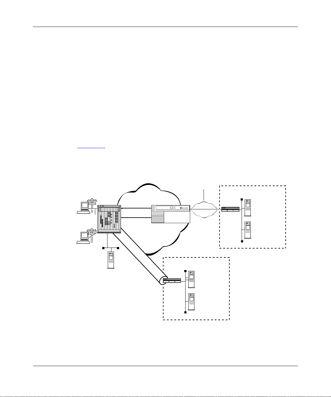
Dial VPN supports both Layer 3 and Layer 2 tunnels on the same ISP network.
Figure 1-1
shows a Dial VPN network with both Layer 3 and Layer 2 (L2TP)
tunnels.
WAN
(PPP or
Frame rela y)
Remote
node
PPP
Remote
node
PPP
RAC
Layer 3 Tunnel
IP Network
L2TP T unnel
GW
Customer Premise
Router
Authentication
Accounting
Authorization
IP Management
Server
Customer Premise
TMS
Router
Authentication
Accounting
Authorization
IP Management
Server
Figure 1-1. Dial VPN Network with Layer 3 and Layer 2 Tunnel s
303509-A Rev 00 1-3
Page 24

Configuring and Troubleshooting Bay Dial VPN Services
Layer 3 Tunneling
In Layer 3 tunneling , the tunnel exi sts between t he Net work Ac cess S erve r (N AS ),
which is a Remote Access Concentrator (RAC), and a gateway router. Both end
points of the tunnel are withi n the ISP netw ork.
Layer 2 Tunneling
In Layer 2 tunneling, the tunnel exists between the Layer 2 Tunneling Protocol
(L2TP) access concentra tor (LAC), usually a remote access concentrator on the
ISP network, and the L2TP network server (LNS), a router or extrane t access
switch on the customer’s home network. Rather than terminating at the remote
access concentrator, the IP tunnel extends the PPP session to the LNS, which acts
as a virtual remote access conc ent rator.
In this guide, the term LAC refers to a remote access server with L2TP
Note:
capabilitie s. The term RAS refers to a remote access server without L2TP
capabilities.
Other features of L2TP include using the In ternet infrastructur e to support
multiple protoc ols a nd unre giste red IP addre sses. Because the dia l-in user ’s data i s
tunneled at Layer 2 and above (in the ISO model), the L2TP protocol is
independent of Layer 3 information. Enterprise customers with unregistered IP
addressing schemes can also use L2TP to reach their home network.
Comparing Layer 3 and Layer 2 Features
Dial VPN supports both Layer 3 and Layer 2 tunneling on the same ISP network.
Both provide secur e network access for dial-in users to their home net works.
Table 1-1
Layer 2 tunneling.
1-4 303509-A Re v 00
briefly compares the most significant features of both Layer 3 and
Page 25

Tunneling Overview
Table 1-1. Layer 3 and Layer 2 Dial VPN Feature Implementation
Dial VPN Feature Layer 3 Layer 2
erpcd
Tunnel management
Protocol Mobile IP L2TP
Encapsulation GRE L2TP
Tunnel end points NAS and gateway LAC and LNS
Dynamic IP address
allocation
Layer 3 protocols
supported
, ACP, or
RADIUS (BSAC)
IP pooling or DHCP IP pooling
IP, IP X IP
How a Dial VPN Network Functions
Any authorized remote user (u sing a PC or dial-up router) who has access to a
phone line and a modem can dial into your network through Dial VPN. A remote
node can be an individua l user dia ling in or a dial-up router (using IP) through a
public-switche d telephone network (PSTN) or an ISDN connection. A remote
user can dial in to a Dial VPN network to connect either to a corporate or home
network or to a third-party ISP. Dial VPN regar ds these as function ally equivalent.
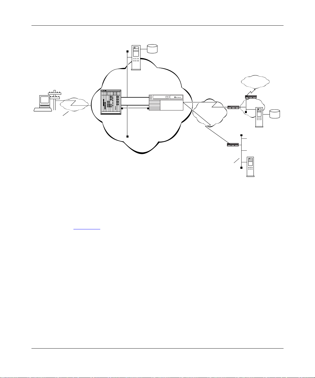
Figure 1-2
configura tion. In reality, a Dial VPN service pro vide r’s network might include
seve ral remote access servers to service a variety of dial-in users, with both Layer
3 and Layer 2 tunnels serving dif ferent types of net works. You can configure Dial
VPN so that its operation is transparent both to users and applications. You may
find it useful to dr aw a map of your own configuration and label the interfaces
with their IP and, if appropriate , frame relay Data Link Connection Identifier
(DLCI) addresses.
is a simplified ill ustration of one possible Layer 3 Dial VPN
erpcd
, ACP, or RADIUS
(BSAC)
303509-A Rev 00 1-5
Page 26
Configuring and Troubleshooting Bay Dial VPN Services
Tunnel
domain
Service
provider network
data
Third-party
Internet
service
provider
network
Customer
network
CPE
CPE
LAN
Customer
RADIUS
Internet
CPE
Third-party
server
Remote
node
PPP
connection
PSTN
Network
access
server (NAS
TMS /erpcd
server
Gateway
T unnel
Frame relay
or PPP
Figure 1-2. Dial VPN Network with Connections to Different Destination Types
Figure 1-2 shows a Dial VPN service provide r netw ork with a Layer 3 tunnel. The
gateway provides connection services both to a corporate LAN and to a
third-party ISP netw ork. This figure shows only one tunnel, but in reality Dial
VPN creates one tunnel for each dial-in connection.
User
data
ISP
RADIUS
server
DVS0012A
In this illustration, a user at a remote node can dial in to a corporate or home
network or a third-par ty ISP b y calling a local phone number associated with that
destination networ k. The network access server handles the call. The service
provider’s networ k uses a standard IP connection between the network access
server, shown here as a 5399 module in a 5000 MSX chassis, and the gateway. A
PPP connection or a frame relay PVC and a static route must exist between the
gatew ay and the customer premise equipment (CPE) router to provide a path for
packets to return to the remote node.
1-6 303509-A Re v 00
Page 27

For Bay Networks route rs used with a Layer 3 Dial VPN tunnel, you must specify
an adjacent host and a static rout e betwe en the gateway and the CPE, and also
between the CPE router and the remot e node. (The adjacent host and static rout es
do not appear in this diagram.) For an illustration of Layer 3 tunneli ng, se e
Chapter 3.
The rest of this guide describ es ho w to install and configur e a Dial VPN service
provider network. It also indicates the requirements for the remote node and the
RADIUS and DHCP servers, with references to the documentation that explains
how to do the configuration.
Dial VPN Network Components
Installing and configuring a Dial VPN service provider network involves several
tasks, some of which you may already have completed. You must:
• Plan the network.
• Install and connect the networ k hardware.
• Install and configure the network software.
Tunneling Overview
• Verify that the elements outsi de the Dial VPN network, specifically the
remote server or servers, the router on the home network, and the remote
dial-in nodes, are proper ly configured.
• Power up, test, and troubleshoot your network.
See the documentation for each of these entities for information on how to install
and configure the m.
This guide deals specifically with how you combine these elements into a Bay
Dial VPN network. The following sections summarize the ele ments of Dial VPN
networks.
Remote Dial-In Nodes
Remote nodes can be PCs (portable hosts) or dial-up routers, using PPP for
dial-up connections. The portable host must hav e PPP client sof tware and a
TCP/IP or IPX protocol stack loaded.
Dial VPN supports dial-up IP (and, for Laye r 3, IPX) over PPP for dial-in PC
clients and IP ove r PPP for dial-in routers connected to LANs.
303509-A Rev 00 1-7
Page 28

Configuring and Troubleshooting Bay Dial VPN Services
The following considerations apply only to Layer 2 (L2TP) tunnels:
• If the PC or router does not have built-in L2TP software capabilities, it dials
into a LAC, which provides a tunnel across the Internet to the c orporate LNS.
This type of connection is the primary focus of this guide.
• If the PC or router is an L2TP client, that is, it has built-in L2TP capability,
the L2TP client software provides a tunnel through a network access server
across the Interne t to the corpora te LNS. A LA C is unnec essary with an L2TP
client.
The main differe nce between connecting an L2TP client and a nonclient is the
starting point of the tunn el. For an L2TP client, the tunnel begins at the PC or
router; for a non-L2TP client, the tunnel be gins at the LAC. All tunnels end at the
LNS.
ISP Network Components for Layer 3 Tunnels
The device s that make up the Dial VPN service provider network can be all at the
same site or can be separated by several “hops” within the same network. A
network with Layer 3 Dial VPN tunnels can consist of a network access server
(NAS), a gateway router that serves as the tunnel end point, and a tunnel
management server.
Network Access Server (NAS)
A network access serv er ( NAS) can be a Remote Access Concentrator
Model 8000 or a System 5000 chassis with one or more Model 5399 Remote
Access Concentra tor modules. Each module is c onfigured with a network address
belonging to the service provider’s address domain. The Remote Access
Concentrator 8000/5 399 includes a dual WAN server, which can support both
analog calls and digita l calls carried over ISDN. The N AS receives and processes
calls from remote nodes and routes data to remote nodes.
This guide uses the term network access server (NAS) to refer to the
Note:
device that performs network access functions, such as answering dial-in user
calls, authenticating tunnel users, building tunnels, and so on. In the Dial VPN
context, this device is usually a Remote Access Conce ntrator (RAC). Other
documents may refer to this same device as a remote access server (RAS).
Essentially, all three terms (NAS, RAS, and RAC) refer to functionally the
same device.
1-8 303509-A Re v 00
Page 29

Tunneling Overview
Gateway
Used only in Layer 3 networks, the gateway can be an ASN, BLN, BLN-2, BCN,
or System 5000 MSX equipped with a Model 5380 module running BayRS
software.
The gateway connects the Dial VPN service provider’s network and the CPE
router on the remote user’s home networ k. The gateway performs con ventional IP
routing functions con figured on interfaces connected to the IP network, through
which the network access servers can be reached.
The gatewa y is the end point of the IP-routed tunnels that tra nsport packets
originated by remo te nodes an d encapsulated by the NAS. The gateway also
connects to the CPE router on the user’s home network. The gateway is the data
terminal equipment (DTE) for frame relay PVCs or PPP connections connecting
to multive ndor RFC 1490-compliant routers on the custo mer premises.
For a frame relay network, the connection is through a frame relay user network
interface (UNI). The gateway forwards traffic between a remote node and the
corresponding node in its home net work by forwar ding packet s ove r a frame relay
PVC connecting the UNI to the IP tunnel. Thus, the gateway uses the IP tunnel
and the frame relay PVC as two links through which it can send the user traffic
from one side to the other.
The PPP connection between the gateway and the customer’s home network
functions in a sim ilar way, except that the co nn ecti on i s thro ugh a PPP int erfac e
instead of a frame relay interface.
In Layer 3 tunneli ng, the gateway may al so act as a RADIUS cli ent to a uthenti cate
the remote user based on information provided from the NAS. The RADIUS
client on the gateway se nds an a uthent ication r eque st to t he RADIUS serv er on the
home network, which either grants or denies the request in a message to the
gatew ay. The gateway then returns this information to the NAS to continue the
process.
303509-A Rev 00 1-9
Page 30

Configuring and Troubleshooting Bay Dial VPN Services
Tunnel Management Server (TMS)
The mechanism for identifyi ng tunneled users is the tunnel management server
(TMS) that resides on a tunnel management server.
For Layer 3 tunne ls, the NAS retr ieves the tunnel configur ation attributes from its
TMS database resid ing on the tunnel management se rver and uses them to build a
tunnel into the customer’s network. Once the tunnel is open, the user can be
authenticated at the customer’s network. Tunnel management can be either
RADIUS or erpcd-based.
• In the RADIUS method, a RADIUS server resides at the service provider site
and manages the TMS database. The NAS and the RADIUS server
communicate using IP over the service provider network. Only Layer 3
tunnels can use this method.
• In the erpcd-based method, the TMS hosts a database application (the Tunnel
Management System) that controls the IP tunnel establishment attempt f rom
the NAS. The TMS runs on the same UNIX host as the Access Control
Protocol (ACP) softwar e. The NAS and the TMS communicate using the Bay
Networks proprietary Expedited Remote Procedure Call Daemon (erpcd or
Secure erpcd). Both Layer 3 and Layer 2 tunnels can use this method.
In either method, the NAS queries the TMS database for the addressing
information it needs to constr uct the IP tunnel. This query is based on the user
domain name and on the policy and state information of the enterprise customer
account when the r emote user dials in. As a Dial VPN networ k a dministrator, you
must provide the user domai n and tunnel ad dressing information to the TMS
database for each enterprise customer. Chapter 5 and Chapter 6 describe the
commands you can use to provision the default TMS database.
ISP Network Components for Layer 2 Tunnels
The followin g sections describe the components of a network with Layer 2
tunnels. A network with Layer 2 Dial VPN tunnels also has a NAS (which may
function as either a LAC or a RAS) and a tunnel management server. The edge
router, however, does not functio n as a ga teway; rather, the tunnel end point is the
CPE router on the customer’s home network. The network itself can have
additional comp onents. This description pertains only to those relevant to Layer 2
tunneling.
1-10 303509-A Re v 00
Page 31

Tunneling Overview
L2TP Access Concentrator (LAC)
The L2TP access concentrator (LAC) resides at the ISP networ k. The LAC
establishes the L2TP tunnel between itself and the LNS. When the remote user
places a call to the ISP network, the call goes to the LAC. The LAC then
negotiates the acti vation of an L2TP tunnel with the LNS. This tunnel carries data
from the remote user to the corporate network.
For more information about the Bay Networks implementation of the LAC in an
L2TP network, refer to Configuring L2TP Services.
Remote Access Server (RAS)
The remote access serve r (RAS) resides at the ISP network. If the remote host is
an L2TP client, the tunnel is established from the remote client through a RAS to
an LNS at the corporate network. In this situation, there is no need for a LAC.
The RAS does not establish the tunnel; it only forwa rds already tunneled data to
the destination.
Tunnel Management Server (TMS)
The ISP network must hav e a mechanism for identifying L2TP tunneled users so
that the LAC can construct the L2TP tunnel. Dial VPN uses a mechanism called a
tunnel management server (TMS); other vendors may use a different method. The
TMS has the same function as for Layer 3 tunnels.
Customer/Home/Internet Service Provider Network
The Dial VPN network interacts with the customer premise equipment (CPE) and
the RADIUS authenticatio n server and the RADIUS accounting serve r on the
customer’s destination network.
Customer Premise Equipment (CPE)
The CPE is a router or extranet switch that connects to the Dial VPN network by
means of frame rel ay PV C s or a PPP connection. The CPE routes traff ic from the
remote nodes to hosts on the home network and from the home network hosts
back to remote nodes.
303509-A Rev 00 1-11
Page 32

Configuring and Troubleshooting Bay Dial VPN Services
Enterprise subscr ibers of this service must configure the CPE router to allow
routing to oc cur be tween the remote nod es and the h osts on t he home netw ork. For
a Layer 3 frame relay circuit, a frame relay PVC, a static route, and (for a Bay
Networks or other non-Cisco router), adjacent host designation must exist
between the CPE and the gate way router on the Dial VPN network. For frame
relay, all Dial VPN circuits must be in the same service record. PPP circuits have
similar requirements, except for the PVC and service record.
L2TP Network Server (LNS)
The L2TP network server (LNS) is a router that resides at the customer’s home
network and serve s as the termination point for Layer 2 (L2TP) tunnels and
sessions.
The LNS authenticates PPP connection requests and allows end-to-end PPP
tunneled connections. An LNS may also work in conjunction with a RADIUS
server to authen ticate dial-in users.
An LNS can accommodate multipl e users, each with hi s or her own L2TP sessio n.
The L2TP session is the virtual end-to-end connection over which the LAC sends
data to the LNS.
In Layer 2 tunneling, the CPE router is also the LNS. For more information about
the Bay Networks LNS, see Configuring L2TP Services.
RADIUS Authentication Server
The RADIUS authenticat ion serve r on the customer’s network is a networ k access
security system. It uses a locally stored and maintained database that contains all
user authentica tion and network ser vice access information to authenticate dial-in
user access requests.
The Dial VPN RADIUS server for Layer 3 tunnels must be on a
Note:
separate physic al device from any RADIUS serv er for Lay er 2 tunnel s or for
switched services . The RADIUS serv er for Layer 2 tunnels can be the same
physical device as for any dial services RAD IUS server.
The RADIUS server has three main funct ions in a Dial VPN L2TP network:
• Authenticating remote users
• Assigning IP addresses to remote users
1-12 303509-A Re v 00
Page 33

Tunneling Overview
• Providing account ing services for corporate billi ng
For Layer 3 tunnels, the RADIUS client of this server resides on the gateway.
The RADIUS client on the ISP network generates a RADIUS authentication
request to the appropriate RADIUS server. This request contains the user
authentication information. The CPE receives the authentication request and
forwards it to the RADIUS server.
Once the user is authenticated, the RADIUS server grants access to the remote
node by returning an authentication accept packet with RADIUS authorization
information to the gateway through the CPE.
For a Layer 3 tunnel, the gateway then forwards the user aut hentication to the
NAS, which initiates an IP tunnel to the gate way using Mobile IP protocol
mechanisms.
For an L2TP tunnel, the RADIUS server database centralizes the authentication
function, eliminating the need to configure each LNS with user names and
passwords. It also assigns an IP address to the remote host to identify the host and
ensure that it is part of its own subnet.
For more information about the Bay Networks implementation of RADIUS user
authentication and accounting, see Configuring RADIUS and the BaySecure
Access Control Administration Guide.
RADIUS Accounting Server
The RADIUS accounting serve r tra cks when users start and end their dial-in
connections and acquire s statistics about each sessio n. BayS ecur e Access
Control™ fully supports RADIUS accounting and provides the network access
server with RADIUS accoun ting information for e very active dial-in session. The
RADIUS accounting server can provide accounting services for the corporate
network, calculating billing charges. For a full description of BaySecure Access
Control and the RADIUS f unctions it supports, see the BaySecur e Access Control
Administrat ion Guide.
303509-A Rev 00 1-13
Page 34

Configuring and Troubleshooting Bay Dial VPN Services
DHCP Server
If you implement the optiona l Dynamic Host Conf iguration P rotoc ol (DHCP) as a
way of dynamically assigning IP addresses to dial-in users, you must also
configure a DHCP server on the customer’s network . F or a detailed description of
using DHCP, see Chapter 8 in this guide.
Additional Planning Information
Appendix A contains a network planning worksheet that you can use in
determining how to configure the BayRS side of your Dial VPN network. You
may not have enough inf ormation yet to complete this worksheet, but if you fill it
in as you go along, it can provide document ation for your network. You may also
find this info rmat ion useful when changing or troubleshooting your network.
Where to Go Next
For a descriptio n of how a packet moves through a Dial VPN network an d other
background information that can help you visualize the data flow through the
network, go to Chapter 2 for Layer 2 tunneling or Chapter 3 for Layer 3 tunne ling.
For informatio n about configuring Dial VPN, go to Chapter 4.
1-14 303509-A Re v 00
Page 35

Chapter 2
Dial VPN Layer 2 Tunneling
This chapter describes how a Layer2 Dial VPN tunnel functions. Among these
concepts are ho w a data packet se nt from a remote node using PPP moves thr ough
a Dial VPN service provider’s network to a corporate or “home” netw ork via a
frame relay or PPP connection. It also explains how the Dial VPN tunnel forms a
path to move data quickly and eff ic iently to and from the remote node through the
Dial VPN service provide r’s IP backbone network.
Dial VPN uses encapsulation technologies and the Layer 2 Tunn eling Protocol
(L2TP) to provide a secure pathw ay for remote users to exchange data with their
corporate hom e network. Regardless of where a remote node is l ocated, it ca n dial
in to its Dial VPN service provider and connect to the home network.
Figure 2-1
an L2TP access concentrator (LAC) and the other tunnel end point is the CPE
router or extr anet switc h on the c ustomer’s home net work. That r outer or switch is
the L2TP network serv er (LNS) , whic h termi nates all L2TP tunnels and sessions
with that network. In this f igure, the dotted line shows the path of the packet
through the tunnel; the Dial VPN service provider network is the ISP networ k.
303509-A Rev 00 2-1
shows the path of a packet in a Layer 2 tunnel. The NAS functions as
Page 36

Configuring and Troubleshooting Bay Dial VPN Services
ISP network
Frame rela y
Remote
host
PC
No L2TP
functionality
PPP
connection
LAC
T unnel
Data
TMS
connection
Figure 2-1. Layer 2 Tu nnel Pac ket Path
Note:
If the dial-in node is conf igured with an L2TP client, that client se rves
as the LAC, and the RAC serves the functi on of a normal network access
server. In this guide, most of the descr iptions use the Remote Access
Concentrator as the LAC for Layer 2 tunnels.
Buildi ng a Netw ork for Layer 2 Tunneli ng
The steps that follow provide a suggested order for configuring your network for
Dial VPN Layer 2 tunneling. For detailed information about each of these steps,
see Chapters 4 through 10.
Corporate network
LNS
RADIUS
server
At the ISP network , co nfigu re the followin g:
1.
• Remote Access Concentrator, serving as the L2TP access concentrator
(LAC)
• Tunnel management server (TMS) on the erpcd server for the
erpcd-based solution
• Access Control Protocol (ACP) server (only for the erpcd-based solution)
• Edge router capable of connecting to the LNS on the customer’s home
network with fram e rel ay or PPP
2-2 303509-A Re v 00
Page 37

Dial VPN Layer 2 Tunneling
Install and configure any intermediate nodes on the WAN .
2.
The WAN can include intermediate nodes. For installation and startup
information, refer to the hardware documentation for each device.
Install the software for the tunnel management server , Remote Access
3.
Concentrator , and (for the
-based solution) Access Control Protocol
erpcd
on the host that serves as the load host for the Remote Access
Concentrator .
For installation instructions, see the Remote Access Concentrator
documentation.
Load the operating software onto the Remote Access Concentrator and
4.
boot the Rem ote A cce ss C o nce ntr a to r.
For detailed descr iptions of the boot procedures, see the Remote Access
Concentrator documenta tion.
Configure the Remote Access Concentrator software, as described in
5.
Chapter 4, to handle PPP dial-in calls from remote nodes, determine
whether they a re tunn el clients, and route the m ap prop ria tel y.
Configure the TMS (i ncluding the aut hen ti ca tio n ty pe ) by addi ng an
6.
entry in the TMS for each domain in the TMS database. See Chapter 5
and Chapter 6 for more information.
When configuri ng the TMS, you can choose either local or remote
authenticati on. Dia l VPN uses a RADIUS serve r on the customer’s home
network to provide authentication and assign IP addresses.
For DHCP address allocat ion, conf igure the TMS with the DHCP parameters,
as described in Chapter 5.
Establish a conne ction between the edge router on the Dial VPN network
7.
and a CPE router (the LNS) on the home network using frame relay or
PPP.
Make sure that the home network is configured to connect to the Dial
8.
VPN network.
Specifica lly, ensure that:
• The RADIUS server on the home network is configured to work with the
RADIUS client on the Dial VPN network. If dynamic IP address
allocation or DHCP is enabled, the RADIUS or DHCP server must have
an allocated pool of addresse s for au thenticated dial-in users an d ha ve
RADIUS accounting enabled.
303509-A Rev 00 2-3
Page 38

Configuring and Troubleshooting Bay Dial VPN Services
• The CPE router that is the end point of Layer 2 tunnels is configured as
the LNS and is configured with a frame relay or PPP connection to the
ISP network (including a static route and an adjacent host if the CPE
router is not a Cisco device).
For instruct ions on configuring the LNS, see Configuring L2TP Services.
• An y sha red information, such as passwor ds, “secre ts,” or phone numbers,
is consistent across the link.
Individually tes t each network component, then test the entire system.
9.
L2TP Packet Encapsulation
The dial-in user sends PPP packe ts to the LAC, which encapsulates these
incoming packets in an L2TP packe t and sends it across an IP network through a
bidirectional tunnel. After the LNS recei ves the packets, it deca psulates them and
terminates the PPP connection.
Figure 2-2
shows how data is encapsulated for transmission over an L2TP tunnel.
2-4 303509-A Re v 00
Page 39

Dial VPN Layer 2 Tunneling
Remote user places a call
PPP IP
Layer 2
protocol
IP/UDP
IP DATA
Data packet moves to the corporate network
LAC
LNS
DATA
PPP
IPL2TP
DATA
L2T0005A
Figure 2-2. L2TP Packet Encapsulation Process
Bay Networks L2TP Implementation
In an L2TP tunnel, the Bay Networks router or extranet switch on the home
network is the LNS. LNS software oper ates on the BLN, BCN, and ASN
platforms.
The Bay Networks LNS has the following characteristics:
• Ea ch slot c an act as an LNS, which means th at one router can ha ve man y LNS
interface s, each with its own address . You can have as man y LNS i nterfaces as
there are available slots on the router.
303509-A Rev 00 2-5
Page 40

Configuring and Troubleshooting Bay Dial VPN Services
• The LNS performs user authenticati on with a RADIUS server to preve nt
unauthorized user s from accessing the network.
• The LNS accepts only incoming calls; it does not place calls to the LAC.
• The Bay Networks L2TP implementation supp orts only IP traffic through the
L2TP tunnel. The LNS supports only numbered IP addresse s.
• The router interface between the ISP and the home network (see Figure 2-4
a leased line operating with frame relay or PPP (including PPP multilink).
Bay Networks recommends th at you use a high-spe ed link, such as T1, for the
leased connection.
• The LNS terminates PPP multilink and PPP encapsula ted data within an
L2TP packet.
• The LNS operates with the LAC implementa tion configured on the Bay
Networks Model 8000/5399 Remote Access Concentrator.
• The host (PC or router) dialing into the ISP network can be on the same
subnet as the IP inte rface on the LNS.
• The LNS supports RIP. RIP is particularly usef ul when the remote host is a
router, because it enables the LNS to learn routing inf ormation from the
remote router.
For a summary of how to conf igure the LNS, see Chapter 8 of this guide. For
complete instruct ions on how to configure a Bay Networ ks rou ter as an LNS, see
Configuring L2 TP Services.
Tunnel Management in L2TP Tunnels
The Bay Networks tunnel management server (TMS), which resides at the ISP
network, stores the TMS database. This database contains the remote users’
domain name, the IP address informati on of each LNS, and other tunnel
addressing information that the network administrator configures. The LAC
requests this information from the TMS to construct the L2TP tunnel.
) is
2-6 303509-A Re v 00
Page 41

When the LAC receives a call, it forw ards the domain name to the TMS. The
domain name is th e por tion of the use r’s add ress that s pecif ies a parti cul ar locati on
in the network. For example, if the user name is jdoe@baynetwor ks.com,
baynetworks.com is the domain name. The TMS looks up the domain name and
verifies that the remote user is an L2TP user. The TMS also provides the LAC
with the addressing information required to establish a tunnel to the correct LNS.
The domain name referred to in this guide is a domain identifier that
Note:
does not foll ow a speci fi c format . It i s not related t o any Domain Na me System
(DNS) protocol requirements.
Security in an L2TP Network
You can configure two layers of security in an L2TP network:
• Tunnel authentication
Tunnel authentication is the process of negotiating the establishment of a
tunnel between the LAC and the LNS.
Dial VPN Layer 2 Tunneling
• User authentication
The network administr ator at the corporate site can configure a RADIUS
server with the names and passwords of authorized users. The server’s
database central izes the authentication funct ion, eliminating the need to
configure each LNS with user names and passwords.
When the LNS receives a call, it forwards the user information to the
RADIUS server, which verif ies whether the user is authorized to access the
network.
You can also co nfigure the LNS to perform user authentication if a RADIUS
server is not part of the network configuration.
The followin g paragraphs describe the Bay Networks implementation of tunnel
and user authentication.
Tunnel Authentication
For Dial VPN Layer 2 tunnel security purposes, you must enable the LNS to
perform tunnel authentication. Tunnel authentication i s the process of negotiating
the establishment of a tunne l.
303509-A Rev 00 2-7
Page 42

Configuring and Troubleshooting Bay Dial VPN Services
During tunnel authenti cation, the LNS identifies the L2TP client or LAC by
comparing the LAC ’s tunnel authentication passw ord with its own password. If
the passwords match, the LNS permit s the LAC to establish a tunnel.
The LAC does not send the tunnel authentication password as a plain-text
message. The exchange of pass words works much like the PPP Challenge
Handshake Authent ication Prot oco l (CHAP). When one side recei v es a cha llenge ,
it responds with a value that is calculated based on the authentication password.
The receiving side matches the value against its own calculation. If the values
match, authentication is successful.
Tunnel authentication occurs in both directions, which means that the LAC and
LNS both try to verify the other’s identity.
You can enable tunnel authentication on the Bay Networks LNS. If tunnel
authenticati on is disabled, which i s the def ault, the LNS sends a default challenge
response to the LA C during the authentication process so that the tunnel can be
established. The LNS cannot send outgoing calls, so it cannot initiate tunnel
authentication.
During tunnel authenti cation, the following exchange of messages takes pla ce:
1.
The LAC sends a tunnel setup message, called the start control connection
reque st (SCCRQ) message to the LNS. This message includes a challenge to
the LNS.
2.
The LNS replies with a tunnel response, a chal lenge response, and its own
challenge message. This is called the start contr ol connection r eply (SCCRP)
message .
3.
The LAC repli es with a challenge response that includes its tunnel
authentication password. This is the start control connection connected
(SCCCN) message.
4.
If this same password is configured for the LNS, the LNS grants approval to
the LAC to estab lish a tunnel.
Figure 2-3
2-8 303509-A Re v 00
shows tunnel authentication and the control messages.
Page 43

Dial VPN Layer 2 Tunneling
ISP network
LAC
SCCRQ
tunnel request and challenge
SCCCN
challenge response
Figure 2-3. Tunnel Authentication Control Messages
After tunnel authentication is complete, it need not be repeated for other calls to
the same LAC.
RADIUS User Authentication
Corporate network
PPP connection
LNS
SCCRP
tunnel response, challenge response,
and LNS challenge
L2T0006A
RADIUS user authentic ation is ena bled b y defa ult on the Bay Netw orks LNS; you
must configur e this feature so tha t the LNS can validate the remote user’s identity
before allowing access to the network.
The network administr ator at the corporate site must configure a RADIUS server
with the names and pas swords of authorized use rs. When the LNS receives a call,
it forwards an authentic ation request with the user infor mation to the RADIUS
server, which verifies whether the user is author iz ed. If the user is permitted
access to the network, the RADIUS serv er replies with an acknowledgment
message and the appropriate IP address inf ormation for that user to make a
connection.
For more information about configuring Bay Networks routers as RADIUS
servers, see Configuring RADIUS.
303509-A Rev 00 2-9
Page 44

Configuring and Troubleshooting Bay Dial VPN Services
RADIUS Accounting
The RADIUS server can provide accounting services in addition to its
authentication services. RADIUS accounting is enabled by default on the Bay
Networks LNS.
The RADIUS accounting serve r calculates billing char ge s for an L2TP session
between the remote user and the LNS. To de termine these charges, the se rver uses
information that it rec eives from the LNS, such as the status of each call and the
number of packets sent during the ses sion. Using this data, the RADIUS server
determines billing c harges, which the network administrator can use to manage
network costs.
The primary RADIUS accounting server can be the same server as the
authentication server or it can be a different server.
For more information about RADIUS accounting, refer to Configuring RADIUS.
L2TP IP Interface Addresses
When configuring the Bay Networks LNS, you must configure an IP address for
every slot that has an L2TP interface. This address is referred to as the L2TP IP
interface address. The L2TP IP interface can be any valid IP address.
The L2TP IP interface address is internal to the LNS. When communicating with
the remote user , the LNS associa tes the user’s IP addr ess, which is a ssigne d by t he
RADIUS server, with the L2TP IP interface address that you configured.
The L2TP IP interface address and the RA D IUS-assigned IP ad dress do not have
to be in the same subnet.
2-10 303509-A Re v 00
Page 45

Remote Router Configuration
If the host at the remote site is a Bay Networks router, you may need to configure
a dial-on-demand circuit for the remote router’s dial-up interface to the LAC at the
ISP network.
Enable RIP on both the dial- on-demand circuit and the attached LAN interface of
the remote router, so that the LNS can learn routing information from the remote
router. To avoid unnecessarily activating the circ u it becau s e o f R I P pa ckets ,
enable dial-optimized routing for the dial-on-demand circuit.
In addition, c onfi gure a de fault or static r oute f or the r emote r outer, which use s the
next-hop address tha t corresponds to the L2TP IP interface address of the LN S.
This de f a u l t o r st a t i c ro ute ena b l e s th e remo t e r o u ter to deliver L2TP packets to
the LNS.
Starting an L2TP Session
The connection process for Layer 2 tunnels is similar to that for Layer 3, but the
end points of t he tunnels a re dif ferent. In L2TP t unneling , th e end point of t he PPP
connection from a LAC or a remote access server (RAS) extends to an L2TP
network server (LNS). Multiple users can communicate through a single tunnel
between the same LAC and LNS pair. Each user transmits and rece ives data in an
individual L2TP session.
Dial VPN Layer 2 Tunneling
Packets flow across an L2TP tunnel during an L2TP session. An L2TP session is
created when an end-to-end WAN connection is established between the remote
host and the LNS.
The L2TP portion of the packets sent thr ough the tunnel contains a header with a
call ID field (also called a session ID) and a tunnel ID field. The call ID field,
which indicate s the sess ion t hat the WAN packet belongs to, is ne goti ated b etween
the LAC and the LNS when the L2TP call is set up. The tunnel ID specifies the
tunnel that the L2TP session is using.
In addition to the fi el ds in the header, the L2TP packet contains a call serial
number, which is a unique number for each L2TP call. This number matches the
call to the L2TP session.
303509-A Rev 00 2-11
Page 46

Configuring and Troubleshooting Bay Dial VPN Services
Examples of L2TP Tunnels
Figure 2-4 shows an L2TP network that uses a LAC to connect to the LNS. The
tunnel is between the LAC and the LNS.
ISP network
Remote
host
PC
No L2TP
functionality
PPP
connection
LAC
T unnel
Data
TMS
Figure 2-4. L2TP Network Using a LAC
Figure 2-5 shows an L2TP network that uses a RAS to connect to the LNS. The
tunnel is between the PC (the L2TP client) and the LNS.
ISP network
Remote
host
PC
T unnel
RAS
Data
Frame rela y
connection
Frame rela y
connection
Corporate network
LNS
RADIUS
server
L2T0003A
Corporate network
LNS
L2TP
client
RADIUS
server
L2T0004A
Figure 2-5. L2TP Network Using a RAS
2-12 303509-A Re v 00
Page 47

Dial VPN Layer 2 Tunneling
Making a Connection Across an L2TP Network
The followin g steps explain how a remote user connects across an L2TP network
that includes a Bay Networks LAC, TMS, and LNS. (See Figure 2-4.)
1.
The remote user dials a LAC at the local ISP network to establish a PPP
connection to the corpora te network.
In the call, the user includes any required information, for example, a user
name, including a domain name and a password. When dialing in, the user
enters a name, for example, jdoe@baynetworks.com; jdoe is the use r name
and baynetworks.com is the domain name.
2.
The LAC receives the call and passes the domain name to the TMS.
If the TMS finds a match for the domain name, a tunnel can be created. The
TMS also checks the number of current connections so that they will not
exceed the maximum number allowed.
If the user is not a tunnel candidate, as determined by the domain name, the
LAC assumes that the remote host is making a regular dial-in request and
authenticates the user acc ordingly.
3.
The LAC tries to establish an L2TP tunnel with the LNS.
For the LAC to send a tunnel request to the LNS, it needs the address of the
LNS. The LAC requests the address from the TMS. It then checks for this
address in its own routing table. Aft er obtaining the address, the LAC sends a
tunnel request to the LNS. The LNS may perform tunnel authentication, if
configured to do so. If the LAC and LNS complete tunnel authentication
successfully, the LAC establishes the tunnel.
4.
After the tunnel is established, the LAC forwa rds the remote user’ s name to
the LNS, which ver if ies the user’s identity with the corporate RADIUS serv er.
If the RADIUS server recognizes the user name, it replies with an
acknowledgm ent and an IP address that it assigns to the remote user for the
duration of the call. This IP address identifies the remote user who may not
have an addre ss of his own.
5.
After the remote user is succ essfully au thentica ted, the user ha s an end-to- end
PPP connection to the corporate network over the Internet.
The tunnel can now carry a user session dur ing which the LAC and the LNS
exchange PPP packe ts.
303509-A Rev 00 2-13
Page 48

Configuring and Troubleshooting Bay Dial VPN Services
When Does Dial VPN Tear Down the Tunnel?
The LAC brings down the tunnel for any one of the following reasons:
• A network failure occur s.
• The LAC or other equipment at the ISP is not operating properl y. If the LAC
fails, all tunnel users are disconnected.
• There are no active sessions inside the tunnel.
An individual se ssion ends when a remote user disconnects the call, but
multiple sessions can ru n inside a single tunnel.
• The system administrator at the ISP ter minates the user connection.
• The LAC is not responding to a Hello packet from the LNS.
For the LAC to rees tablish a tunnel, the remote user must place a new call.
If the LAC fa ils, all tunnel users are disconnect ed and the active us e r counts are
decremented. Ho wev er, there is no quick way to determine when a LA C fails . The
logging connection may not be reset until after new tunnel users have connected.
When a LAC starts, one of the f irst things it does is open its A CP-logging
connection. When a new logging connection opens, TMS decrements the
appropriate co unts for eac h domain t hat had a us er connect ed to the LAC . If thi s is
the first time the LAC has come up, then there will be nothing to decrement.
If you enter the
Note:
reset security
command, a new u ser who tries to make
a connection with the LAC causes the maximum number of users count to
decrement, even though users with exis ting connections are still connec ted.
This means that the maximum number of users count may be exceeded. As
users with existing connections disconnect, the count will synchronize and
correspond to the actual number of users connected.
If the TMS fails, a LAC can detect the failure through the failure of the logging
connection. The LAC falls back to secondary ser vers, if any. Unless the data base
is shared by the TMS servers, the count of current users is lost.
If the TMS database runs out of disk space while tms_dbm is running, the user
sees an error message. The error messa ge may not state what caused the error. If
there is a shortage of disk space and erpcd cannot create a lock file or add a LAC
to the TMS database, TMS generates a syslog message and t he user cannot make a
connection to the LA C.
2-14 303509-A Re v 00
Page 49

Chapter 3
Dial VPN Layer 3 Tunneling
This chapter describe s how a Layer 3 Dial VPN tunnel functions. Among these
concepts are ho w a data pack et sent from a remote node using the point-to-point
protocol (PPP) moves through a Dial VPN service provider’s network to a
corporate or “home” network via a frame rela y or PPP connecti on. It also explains
how the Dia l VPN tunnel forms a path to move data quickly and efficiently to and
from the remote node through the Dial VPN service provider’s IP backbone
network.
Dial VPN uses the Generic Routing Encapsulat ion (GRE) protocol and the Mobile
IP protocol to provide a secure pathway for remote users to exchange data with
their corpora te home netwo rk ove r a Layer 3 tunn el. Re gardle ss of whe re a re mote
node is located, it can dial in to its Dial VPN servi ce provider and connect to the
home network.
For example, Figure3-1
from the NAS, through the Layer 3 tunnel to the gatewa y, across a frame relay
connection, and on to the home network. In this figure, the dotted line shows the
path of the packet through the tunne l; the Dial VPN service provider netw ork is
the ISP network.
303509-A Rev 00 3-1
shows how a packet moves in an erpcd-based network
Page 50

Configuring and Troubleshooting Bay Dial VPN Services
A
BayD VS service
provider network
T unnel
Data
Tunnel
management
server/ACP server
Gateway
Remote
node
PPP
connection
Remote
annex
Figure 3-1. Layer 3 Tu nnel Pac ket Path
Buildi ng a Netw ork for Layer 3 Tunneli ng
Frame rela y
connection
Corporate
"home"
network
DVS0001
The steps that follow p ro vide a suggested order for conf iguring your net work. For
detailed information about each of these steps, see Chapters 4 through 10.
At the ISP network , co nfigu re the followin g:
1.
• Remote Access Concentrator, serving as the network access server (NAS)
• Tunnel Management Server (TMS), either on the UNIX erpcd server for
the erpcd-based solution or on the service provider net work RADIUS
server for the all -RADI US solution
• Access Control Protocol (ACP) server (only for the erpcd-based solution)
• Bay Networks r outer that serves as the gateway to the remote user’s ho me
network
Install and configure any intermediate nodes on the WAN .
2.
The WAN can include intermediate nodes. For installation and startup
information, refer to the hardware documentation for each device.
3-2 303509-A Re v 00
Page 51

Dial VPN Layer 3 Tunneling
Install the software for the tunnel management server , Remote Access
3.
Concentrator , and (for the
-based solution) the Access Control
erpcd
Protocol on the UNIX host that serves as the load host for the Remote
Access Concentrator.
For installa tion information, see the Remote Access Concentrator
documentation.
Load the operating software onto the Remote Access Concentrator from
4.
the UNIX load host and boot the Remote Access Concentrator.
For detailed descr iptions of the boot procedures, refer to the Remote Access
Concentrator documenta tion.
Configure the Remote Access Concentrator software, as described in
5.
Chapter 4, to handle PPP dial-in calls from remote nodes, determine
whether they a re tunn el clients, and route the m ap prop ria tel y.
For the all-RADIUS s oluti on, in stall and conf igure the RADIUS server on
6.
the service provider network to support the TMS database.
For more information about installing and configuring RADIUS servers on
the ISP network, see Chapter 6.
Configure the TMS (i ncluding the aut hen ti ca tio n ty pe ) by addi ng an
7.
entry in the TMS for each domain in the TMS database. Refer to
Chapter 5 and Chapter 6 for more information.
When configuri ng the TMS, you can choose either local or remote
authenticati on. F or both the erpcd-based and the all-RADIUS solutions, Dial
VPN uses remote authentication; that is, a RADIUS server on the customer’s
home network provides authentication and assigns IP addresses.
For DHCP address allocat ion, conf igure the TMS with the DHCP parameters,
as described in Chapter 5.
Configure the gateway, including the RADIUS client, using Site Manager ,
8.
then boot the gatewa y.
Configure the gateway with an IP connection to the Dial VPN network and a
frame relay or PPP connection to the CPE router on the remote use r’s home
network. Configure a RADIUS client on the gatew ay. For information on
configuring the gateway, see Chapter 7.
Establish a connection between a gateway on the ISP networ k and a CPE
9.
router on the home network using fra me re lay or PPP.
303509-A Rev 00 3-3
Page 52

Configuring and Troubleshooting Bay Dial VPN Services
Make sure that the home network is configured to connect to the Dial
10.
VPN network.
Specifica lly, ensure that:
• The RADIUS server on the home network is configured to work with the
RADIUS client on the Dial VPN network. If dynamic IP address
allocation or DHCP is enab led, the RADIUS or DHCP serv er must ha ve a
pool of addre sses all ocate d for a uth enticat ed dial- in users. F or dynamic IP
address allocation, you must have RADIUS accounting enabled.
• The CPE router is c onfigured with a frame relay or PPP connection to the
Dial VPN gateway ( including a static route and an adjacent host if the
CPE router is not a Cisco device), and a separate but similar frame relay
or PPP connection to the RADIUS client on the gateway.
• An y sha red information, such as passwor ds, “secre ts,” or phone numbers,
is consistent across the link.
The Dial VPN RADIUS server for Layer 3 tunnels must be on a
Note:
separate physic al device from any RADIUS serv er for Lay er 2 tunnel s or for
dial services. The RADIUS serv er fo r Layer 2 tunnels can be the same
physical device as any dial services RADIUS server.
Individually tes t each network component, then test the entire system.
11.
How Tunnel Management Works
Tunnel management operates differently on erpcd-based and RADIUS-only
networks, but the end result is the same.
Tunnel Management in an erpcd-Based Network
For an erpcd-based network, the tunnel management server (TMS) runs on the
same host as the Remote Access Concentrator (erpc d) and Access Control
Protocol (A CP) software. The TMS verifies that the user at the remote node is a
Dial VPN user . If the dom ain por tion of th e user name e xis ts in the TMS data base ,
ACP increa ses the number of current users by one and sends a Grant message to
the NAS. The Grant message contains the tunnel addressing inf ormation needed
to send a packet from the remote node to the home network.
3-4 303509-A Re v 00
Page 53

Dial VPN Layer 3 Tunneling
The Grant message contains the following information, which is stored in the
TMS database:
• Remote node’s domain name
• Domain name information server (DNIS) -- for Model 8000/5399 platforms,
the DNIS is the called number; for other platforms, it is 0 (zero)
The default value for the DNIS is 0. The NAS administrator can change
Note:
this value .
• Hom e agent’s IP address on the gate w ay (the IP address of the gate w ay end of
the IP tunnel)
• Current number of users
• Type of connection between the ISP network’s edge router or gate way a nd the
CPE router on the remote node’s home network
• Primary and secondary RADIUS server IP addres ses
• Authentication protoc ol information
For each tunnel user, the NAS sends this information to the RADIUS c lient on the
gateway, which in turn sends an authentication and address request to the
RADIUS server on the remote node’s home network. Whe n the RADIUS serve r
responds, authenticating the user, the NAS establishes the tunnel.
Tunnel Management in an All-RADIUS Network
The all-RADIUS solution integrates the TMS database functions into the
RADIUS server that resides on the service provider networ k. This RADIUS
server recogniz es the format of the VPN identifier in the user name and returns
tunnel information to the NAS. The NAS uses the tunnel information to establish
a connection to the gateway. Once the connection is made, the user authentication
information is forw arde d to the indicated authentication se rver.
Refer to Chapter 5 for more information about the contents of the TMS database.
303509-A Rev 00 3-5
Page 54

Configuring and Troubleshooting Bay Dial VPN Services
How the TMS Database Works
The TMS database (by default, UNIX ndbm) resides on the tunnel management
server, which resid es on the service pro vider’s network. The main f unction of this
database is to v erify the user name (or domain) inf ormation supplied by the NAS.
It also supplies the NAS with the tunnel addressing information (in the Grant
message) that it needs to create a tunnel for a remote user. The Dial VPN
administrator ent ers the domain information and the tunnel addre ssing
information into the dat abase as part of the TMS configuration process.
When the TMS receives a lookup request from the NAS, it parses the user name
into the user and domain name and DNIS, and creates a Domain/0 or
Domain/DNIS key. The TMS database uses this key to f ind a match in the
database with the supplie d user name. If the key matches an existing e ntry, the
TMS checks to make sure that the maximum number of users is less than the
configure d maximum. If so, th e TMS sends a Grant messa ge indica ting that t his is
a Dial VPN user. The Grant message contains the tunnel addressing information.
Since ndbm does not have a locking feature, Bay Networ ks has implemented
application- le vel loc king to pre ve nt users from updati ng the databas e while others
are using it. The lock file s are created in the UNIX install directory.
The erpcd and tms_dbm utilitie s use a common library of functions (in
Note:
tms_lib .c) to access the database. If you repla c e the database and provide
access to it through the same libr ary fu nction interface, as required, the same
commands will work. You can replace the default database engine with a
standard UNIX relational database, such as Sybase, Informix, or Oracle, or
with one you have created yourself. For information about how to replace the
default TMS database, contact the Bay Networks Technical Solutions Center.
Dynamically Allocating IP Addresses
Dial VPN lets you choose betwee n two methods of dynamic IP address allocation:
• Dynamic Host Configurat ion Protocol (DHCP) requires its o wn server and
allocates IP addresse s for a configurable, renewable period, called a lease.
• IP address pooling uses the Dial VPN RADIUS server and allocates an IP
address from a configured pool for the duration of the user’s dial-in session.
The following sections describe each of these methods.
3-6 303509-A Re v 00
Page 55

Using DHCP for Dynamic IP Address Allocation
This method requires a DHCP server on the home/co rporate network. This server
communicates with a DHCP client proxy resi ding on the gateway. The server
dynamically allocate s a n IP address for a dial-in user when the client proxy
requests one.
Based on RFC 2131 and its extensions, DHCP provides a scalable method of
dynamically alloc ating IP addr esses to remo te users a nd a way of managing th e IP
addresses dynamically assigned to dial-in users. This implementation supports:
• Standard DHCP operation, as described in RFC 2131
• Interoperation with standard DHCP servers
• Use of both primary and secondary DHCP servers
• DHCP leases with as many users as there are tunnels
• Both Dial VPN (tunneled) and non-tunneled users
• Getting IP addresses through either the local or the remote DHCP client
proxy, in addition to other methods that Dial VPN supports, depending on
how the Dial VPN subscriber is provisioned
Dial VPN Layer 3 Tunneling
How DHCP Works
DHCP implements the concept of IP address leasing. An authenticated dial-in
user receives an exclusive right to use an assigned IP address for a specific,
configurable period of time, called a “lease.” When this lease expires, the DCHP
client proxy c an rene w the lease o r let it l aps e, return ing the I P address t o the pool.
DHCP lets a network manager specify a range of assignable IP addresses without
requiring that each IP addre ss be ti ed to a specific MAC (har dware) address. The
DHCP server leases an IP address to each dial-in user and dynamically maintains
a table that links a user’s IP and MAC addresses. For users who need a fixe d IP
address, a network manager can also specify a permanent assignment. A singl e
NAS can communicate and maintain DHCP leases with as many DHCP servers as
there are ports on the N AS (up to 48 or 62, depending on the model).
When a remote user dials in to a network access server (NAS), Dial VPN
performs the usual authenticat ion function s. When the gate w ay retur ns t he Mobile
IP (MIP) authentication r esponse to the NAS, however, the NAS sends the
gateway a MIP dynamic address allocation (DAA) request. The gateway sends a
303509-A Rev 00 3-7
Page 56

Configuring and Troubleshooting Bay Dial VPN Services
DHCP discover reque st to the DHCP server on the home network, and the server
responds with an acknowledgment (ACK) if the request is successful. The
gatew ay then sends the MIP DAA response back to the NAS, and the rest of the
negotiation proceeds as usual. Figure 3-2
shows the entire proc ess.
Remote
Node
LCP negotiation
CHAP initiation
CHAP completion
NCP negotiation
Disconnect
Connect
NAS TMS Gateway
Auth/Info Req
Grant w/info
MIP authentication request
MIP authentication response
MIP DAA request
MIP DAA response
MIP registration request
MIP registration response
Open Communication
Terminate msg
RADIUS
Auth Req
Auth Resp w/info
Acct Start
DHCP discover/request
Accounting
Server
Acct Response
DHCP response/ack
Server
DHCP
Server
Local
Node
MIP terminate request
MIP terminate response
MIP HAA request
MIP DAA response
MIP DAA
Acct Stop
Acct response
Address release
Address response
DHCP
DVS0009C
Figure 3-2. DHCP Operational Timeline
3-8 303509-A Re v 00
Page 57

Using RADIUS for Dynamic IP Address Allocation
Each dial-in user retains exclusiv e uses of a unique IP address for the duration of
the dial-in sessio n. Dia l VPN relies on the Bay Secure Access Co ntrol (BSAC)
RADIUS server on the user’s home network to pr o vide th ose addresse s, al locat ing
them either statically or dynamically. In static allocation, the RADIUS
administrator as signs specific addres ses for specific users. In dynamic allocation,
the administrator allocates a pool of IP addres ses from which the RADIUS server
selects an address to assign.
The network administr ator configures the IP address of a RADIUS server on the
home network that uses dynamic addre ss a llocation and also enables dynamic
address allocati on on the gateway for that serv er connection.
When a user dials in to a network using dynamic address allocation, RADIUS
authenticates the user and assigns an IP address from the pool. RADIUS also
maintains a data base of assig ned ad dresses. This pr e vent s dupl icat e assignments if
the server fails.
When the connection ends, the relea sed IP address returns to the pool, at the end
of the assignment queue.
Dial VPN Layer 3 Tunneling
To implement dynamic IP address allocation, Dial VPN requires that the BSAC
software be instal le d on the RADIUS server on the customer’s home network.
BSAC is a robust implementation of the draft IETF RADIUS specif ication,
compliant with RFC 2058 and RFC 2059.
For informatio n about BaySecure, see the BaySecure Access Control
Administrat ion Guide.
How Dynamic I P Address Allocati on Works
Dial VPN implements d ynamic IP addr ess a ssignment usi ng the Site Mana ger and
BaySecure Access Control (BSAC). Using Site Manager, the ISP network
administrator f irst enables RADIUS accounting on the gateway.
303509-A Rev 00 3-9
Page 58

Configuring and Troubleshooting Bay Dial VPN Services
The BSAC (RADIUS) administr ator at the cust omer’s site must ente r one or more
IP address ranges to be used as a pool of assignable addresses. For each remote
user , the RADIUS administr ator can enter either a specif ic IP address or allow the
assignment of an I P address from the pool. The administra tor can, in fact, set up a
standard profile with “assign from pool” specified, and apply this profile to many
users at once.
The Current Users display identifies the active users and their assigned IP
addresses, so that the RADIUS administrator can tell which user has which
address. In addition, the administrator can release any assigned address that is no
longer in use by select ing that address and clicking on Clear. For more
information about assigning and managing IP addresses, see Configuring
RADIUS.
Dynamic address assignment is not available for IPX.
Note:
Assigning Addresses
All available IP addresses are in a queue. The first address in the queue is the first
one assigned. Released ad dresses return to the end of the queue for reassignment.
RADIUS saves all current address assignments in a database to prevent duplicate
address assignments if the server fails.
The gateway on the ISP network is a client of the RADIUS server on the
customer’s network; t hat is, it provi des a ser vice to the di al-i n user , such as PPP or
®
Telnet
. The client is responsible for passi ng user information to the designated
RADIUS server. The RADIUS server receives the request and returns a response
to the client that it has successfully received the request.
The client and the RADIUS server authenticate the transactions between them
through the use of a shared secret, which is never sent over the network. Both
must be configured with the same secret for authentication to take place.
Each service that the NAS provides to a dial-in user constitutes a session; the
beginning of the session is the point at which service i s first pro vided, and the e nd
of the session is the point at which the service ends. A user can have multiple
sessions in parallel or in series if the gateway suppor ts that, with each session
generating a separate sta rt and stop record with its own session ID. Figure 3-3
shows the sequenc e of e vents in dynamic IP address assignm ent.
3-10 303509-A Re v 00
Page 59

Dial VPN Layer 3 Tunneling
Remote
Node
LCP negotiation
CHAP initiation
CHAP completion
NCP negotiation
Disconnect
Connect
RAS TMS Gateway
Auth/Info Req
Grant w/info
MIP authentication request
MIP authentication response
MIP DAA request
MIP DAA response
MIP registration request
MIP registration response
Open Communication
Terminate msg
RADIUS
Auth Req
Auth Resp w/info
Acct Start
Accounting
Server
Acct Response
DHCP discover/request
DHCP response/ack
Server
DHCP
Server
Local
Node
MIP terminate request
Acct Stop
Address
MIP terminate response
Response
release
DVS0018A
Figure 3-3. Dial VPN Dynamic IP Address Management Sequence
At the start of service delivery, a client configured to use dynamic IP addressing
generates a start packet describing the type of servic e being delivered and the user
to whom it is being delivered. The client sends that information to the RADIUS
303509-A Rev 00 3-11
Page 60

Configuring and Troubleshooting Bay Dial VPN Services
server, which sends back an ackno wledgment that it has recei ved the packet. At
the end of service delivery, the client sends the RADIUS server a Stop packet
describing the type of serv ic e that was delivered. The se r ver sends back an
acknowledgment that it has received the packet.
The client se nds a start or stop packet o ver the network, persisting until it receive s
an acknowledg ment or times out. The client can also forward the requests to an
alternate server or servers if the primary server is down or unreachable. The
RADIUS server may request other servers to satisfy the request. In this case, it
acts as a client.
If the RADIUS server cannot succ es sfully record the start or stop packet, it does
not send an acknowledgment to the client.
Starting the Connection
When a user at a remote node dials in to a Dial VPN service provider, the NAS
first determines whether t his i s a tunnel c andida te. If so, t he N AS f i rst acce sses the
TMS database and contacts the gateway, which starts the authentication process.
The gateway gets an IP address from the RADIUS server on the user’s home
network, and the Remote Access Concentr ator builds a tunnel to the gateway and
starts sending the GRE-encapsulated packets. The process involves the following
steps.
A user at a remote node dials the phone number of a Dial VPN service
1.
provider. The user also enters the required user information.
User information usually c onsists of a user name and a password.
The remote node sends a PPP packet to start the connection process.
2.
The NAS receives the data packet and passes the user name to the TMS
3.
on the Dial VPN service provider’s network to determine how to process
the packet.
For Dial VPN, the user name must contain one “at” sign (@), f ollowed by at
least one period (.) and at leas t a 3-character extension . F or example, the user
name can be lee@abc.com. In this example, lee is the user name that the NAS
uses for authentication. The string @abc.com is the domain name that Dial
VPN uses to look up this user’s entry in the TMS database.
3-12 303509-A Re v 00
Page 61

Dial VPN Layer 3 Tunneling
If the TMS finds a match in its database for both the user and domain names,
it determines that thi s user is a Dial VPN user and a candidate fo r tunnel
creation. The TMS then checks that the number of cur rent c onnections does
not exceed the maximum number of users allowed.
Note:
The system administrator can change the default requirement s for the
Dial VPN user name format as needed.
If the TMS determines that the user is not a tunnel candidate, the NAS first
treats the request as a proxy RADIUS request an d attempt s to authentic ate this
user in the usual way. See the description of proxy RADIUS in the BSAC
Administrat ion Guide for your platform.
Note:
The TMS may deny a tunnel request for a number of reasons; for
example, if the maximum number of users has been reached, if the TMS does
not find a match for the domain name in its database, or if the authentication
request fails. If the tunnel request is denied, the connection between the NAS
and the remote node is dropped.
If the dial-in reque st is a tunnel candidate, the NAS starts the
4.
authentication process and builds a tunnel.
Once it determines that thi s reque st is a tunnel candidate, the TMS tells the
NAS to contact the gateway for remote authentication. For a given domain,
authenticati on and address allocati on can take place loca lly, using ACP (in an
erpcd-based netw ork ), or remotely, using RADIUS and DHCP on the
customer’s network. If the reque st is not a tunnel candidate, the NAS uses
local (instead of remote ) authe ntication.
The NAS rece ives the remote node’s address, the source of which depends on
the type of authentication and the type of IP address allocation.
The RADIUS client on t he gateway s ends a request to the RADIUS server
5.
on the home network to authenticate the remote user.
During remote a uthentica tion , the RADIUS authe ntication serv er on t he home
network veri fies that the remote node is author iz ed to access the home
network and de termines whi ch network se rvice s the r emote no de is a llo wed to
use.
The DHCP server or the RADIUS serv er on the home networ k assign s an
6.
IP address and incl u des that a dd ress in the repl y to the gatew ay.
303509-A Rev 00 3-13
Page 62

Configuring and Troubleshooting Bay Dial VPN Services
If the home network is configured to assign IP addresses dynamically using
DHCP, the DHCP serv er select s an IP addre ss from its pool and issue s the end
user a renewable “lease” on that address. Alternatively, the DHCP
administrator may ass ign a fixed IP address to particular users. In either case,
the DHCP server returns the assigned IP address in its reply to the gateway.
If the home network is configured to assign IP addresses using RADIUS,
either statica lly or dynamically, the RADIUS server perfo rms the address
allocation. If the RADIUS administrator has alloc a ted a pool of assignable IP
addresses for dial- in users, and if the RADIUS client on the gatewa y is
configure d for dyna mic IP address assignment , the RADIUS serv er assi gns an
address from that pool. Alternatively, the RADIUS administrator may have
assigned a specific address for that particular user. In this case, RADIUS uses
that assigned addres s. The RADIUS server reserves the assigne d IP addre ss
for that user until the session terminates.
When authentication and addr ess al locat ion are complete, the NAS st arts
7.
sending packets from the remote node to the gateway via the newly
created tunnel.
A Day in the Life of a Layer 3 Packet
The next sections explain how a packet mov es through a Layer 3 Dial VPN
network and returns to the remote node. Figure 3-4 shows the process.
As the packet move s from the remo te node to the home network, different pieces
of the Dial VPN network must encapsulate (add) and decapsulate (strip of f) the
protocol-specific envelope around the data pack et.
3-14 303509-A Re v 00
Page 63

A
Dial VPN Layer 3 Tunneling
PPP packet
Flag FlagAddress Control Protocol Data FCS
GRE packet
CRKSs T FlagControl V ersion Protocol
Frame Rela y packet
Opening
Flag
Address Information FCS Data
Control
Remote node
Remote annex
T ype
Gateway
Data T unnel ID
Closing
Flag
CPE Router
Data packet moves onto home netw ork
DVS0003
Figure 3-4. Packet Encapsulation and Decapsulation Process
303509-A Rev 00 3-15
Page 64

Configuring and Troubleshooting Bay Dial VPN Services
How a Packet Moves Through a Dial VPN Network
A data packet mov es fro m a remote node to the Dial VPN servic e provider’s
network through a tunnel created for the remote node to a gateway, which sends
the data to the remote user’s home network through a frame relay connection.
Here are the steps involved in this process.
The remote node sen ds a PPP packet to the NAS to establ ish a
1.
connecti on.
The PPP packet contains flag f ields to indicate the beginning and end of a
frame, an address fie ld to indicate the device that originated the frame, a
control fie ld to indicate the type of frame (information or administrative), a
protocol fi eld tha t i ndicates the operative n etwork la yer protocol, the da ta, and
the frame check sequence that shows the sequence order of the frame. See the
manual Configur ing PPP Services for more information about the PPP
packet.
The NAS strips off the PPP protocol-specific fields and encapsulates the
2.
data into a GRE packet. The GRE packet moves through the IP tunnel to
the gateway.
The GRE packet contains checksum information and flag bits to indicate that
a routing and a key field are present; a control field to indicate the type of
frame; a tunnel flag to i ndicat e that there is a tunne l ID present; a version f ield
to indicate th e ve rsion of IP ( or IPX) r unni ng on the Inte rnet; the proto col type
used (IP or IPX); the tunnel identifier; and the original data from the data
packet. Refer to IETF RFC 1701 or R FC 1490 for more information about the
GRE packet.
The checksum, control, tunnel flag, and version fields should be 0.
Note:
The gateway decapsulates the GRE pac ket information and puts the data
3.
into a frame relay or PPP packet.
The frame relay or PPP packe t follows the str uctural conventions for a packe t
of that type. For more information about the frame relay or PPP packet
structure, see Configuring Fr ame Relay Services, Configuring Dial Services,
or Configurin g PPP Services.
The gateway sends the frame relay or PPP packet to the CPE router on
4.
the home network.
3-16 303509-A Re v 00
Page 65

The CPE router decapsulates the frame relay or PPP packet and routes
5.
the data to the intended recipient on the home network.
How a Packet Returns to the Remote Node
To send packets fro m the home netwo rk to a remote node, Dial VPN reverses the
process descr ibed i n the pre vi ous secti on. The tunn el e nsures tha t packet s from the
home network reach the remote node, regardless of where it is located.
The Dial VPN gate w ay inte rcept s and for ward s packe ts t o the re mote node us ing a
care-of address that is specified to the gateway during the connection process.
This address, which is usually the address of the Dial VPN Remote Access
Concentrator, is the IP address of the other end point of the tunnel. When the
gateway encapsulates the frame relay packet in a GRE packet, it includes the
Remote
node
care-of addres s. Figure 3-5
from the home network to a remote node through an erpcd-based network.
provider network
Network access
PPP
connection
server (NAS)
shows a simplified view of how a data packet moves
Service
T unnel
Data
Gateway
Tunnel
management
server
Dial VPN Layer 3 Tunneling
Frame rela y
connection
Customer
"home"
network
Static routes
The gateway sends the packet to the
NAS's
care-of address
decapsulates the GRE information
and then encapsulates the data with
PPP information. The NAS
sends the PPP packet to the
remote node.
. The NAS
The packet moves from the CPE
router to the gateway via static routes.
The gateway decapsulates the frame
relay information and then encapsulates
the data with GRE information. The gateway
sends the GRE packet to the care of address.
DVS0013A
Figure 3-5. Sending a Packet to a Remote Node
303509-A Rev 00 3-17
Page 66

Configuring and Troubleshooting Bay Dial VPN Services
The data packe t travels from the home networ k to the remote node using a similar
process of encapsulat ion and decapsulation to respond to the format required at
various points throughout the Dial VPN network. The differences are:
• The data packet must return from the CPE router on the home network to the
gateway on the Dial VPN network via a static route. Figure 3-6
static routes us ed to return da ta from a home net work to a gat ew ay on the Dial
VPN network.
• If the CPE router is a Bay Networks (or similar) router, a nonexistent,
“dummy” adjacent host must be configured on the same IP subnet as the
frame relay interface of the CPE router. This fulfills an addressing format
requirement, but has no effect on the actual packet routing.
• The gateway se n ds the GR E pac ket to the remo t e node’s care-of address on
the NAS, and the NAS forwards the packet to the remote node.
shows the
1.1.1.2
Adjacent host/
next hop
Frame rela y
PVC
Static route
Dial-up
user
3.1.1.X
RAC
BayD VS service
provider's network
T unnel
Gateway
RADIUS
client
DLCI = 101
2.2.2.1
Frame relay
port on gateway
Static route
Figure 3-6. Static Routes from a CPE Router to a Dial VPN Gateway
Data packets m ove bac k and for th betwe en the r emot e node and the home network
through the established tunnel until the remote node disconnects from the Dial
VPN network or an error occurs. When either situation occurs, Dial VPN tears
down the tunnel.
3.1.1.0
Home/
corporate LAN
1.1.1.1
CPE
RADIUS
server
DVS0007A
3-18 303509-A Re v 00
Page 67

When Does Dial VPN Tear Down the Tunnel?
Dial VPN tears down the tunnel whe n an y of the following situations occurs:
• The remote node using that tunnel disconnects.
• Either the NAS or the TMS is not operating properly.
• Tunnel renewal fails.
• The administrator terminates the user co nnection.
If the NAS fai ls, all tunnel users are disconnected a nd the active user counts are
decremented. Ho wev er, there is no quick wa y to determine when a NAS fails . The
logging connection may not be reset until after new tunnel users have connected.
When a NAS starts, one of the f irst things it does is open its A CP-logging
connection. When a new logging connection opens, TMS decrements the
appropriate co unts for eac h domain that had a us er connect ed to the NAS . If thi s is
the first time the NAS has come up, then there will be nothing to decrement .
Dial VPN Layer 3 Tunneling
If you enter the
Note:
reset security
command, a new u ser who tries to make
a connection with the NAS causes the maximum number of users count to
decrement, even though users with exis ting connections are still connec ted.
This means that the maximum number of users count may be exceeded. As
users with existing connections disconnect, the count will synchronize and
correspond to the actual number of users connected.
If the TMS fails, a NAS can detect the failure through the failure of the logging
connection. The NAS falls back to secondary serv e rs, if any. Unless the database
is shared by the TMS servers, the count of current users is lost.
If the TMS database runs out of disk space while tms_dbm is running, the user
sees an error message. The error messa ge may not state what caused the error. If
there is a shortage of disk space and erpcd cannot create a lock file or add a NAS
to the TMS database, TMS generates a syslog message and t he user cannot make a
connection to the N AS.
303509-A Rev 00 3-19
Page 68

Page 69

Chapter 4
Configuring the Remote Access Concentrator
This chapter describes how to use the command line interface (CLI) commands to
configure a Remote Access Concentrator as a network access server (NAS) for
Dial VPN. For details regarding your specific device, see the docume ntation for
the particular model you are conf iguring (Table 4-1
Table 4-1. Wh ere to Fi nd C o nf ig uration Informat i on
For Informati on About See This Guide
).
Using the V ersalar Config Utility with
Remote Access Concentrators
Remote Access Concentrator configuration
and administra ti on procedures, incl uding a
detailed description of all na and
commands and parameters
admin
Managing Remote Access Concentrators
Using the Versalar Config Utility
• Quick-Start Guide for Remot e Access
Concentrators
• Managing Remote Access
Concentrators Using Command Line
Interfaces
You configure the Remote Access Concentrator by attaching a PC in terminal
emulation mode or an ASCII terminal to the console port of the device.
Installing and Configuring the RAC Software
This section provides an overview of the installation and configuration process,
highlighting area s of part icular concern.
T o f aci litate tr oubleshoot ing, test each element of your syste m after you
Note:
configure it and before proceeding to the next phase of the configuration.
303509-A Rev 00 4-1
Page 70

Configuring and Troubleshooting Bay Dial VPN Services
Install the RAC software.
1.
Use the installati on script supplied for the RA C, as described in the
documentation for the particular device you are insta lling.
As part of the hardware insta llation, you may have issued ROM monitor
commands through a terminal connected to the console port located on the
RAC. These commands let you set a subset of the configuration (EEPROM)
parameters, including the unit’s IP address, required for booting the RAC.
You can also spe cify parameter value s that are required if the network
configura tion differs from the default values. See th e hard wa re installation
guide for the Remote Access Concentr ator you are installing for the list o f the
ROM Monitor commands and their defa ult values.
Boot the RAC software (standard installation).
2.
The Remote Access Concentrator get s its operational code by downloading it
over t he network from (among ot her sources) a UNIX host tha t runs RAC file
server softwa re. The RAC boots each time it is powered up and whenever it
boot
receives a
command. You specify the source of the boo t image b y sett ing
the preferred load host.
Set up the dial-in port on the RAC for dial-in and enable ACP or
3.
RADIUS (BSAC) security for PPP on all ports.
Configure security on the RAC using either ACP (for an erpcd-based
network) or BSAC (for a RADIUS-only network), and configure the dial-in
ports. To display the cur rent port settings, enter:
show port ppp
To change a particular setting, enter the
set po rt
command along with the
parameters you want to change. The settings relevant to Dial VPN are:
set port mode auto_detect
set port type dial_in
set port slip_ppp_sec urity y
set port ppp_security_pr otocol chap (<--- This could be chap, pap, or
pap-chap.)
For erpcd-based networ ks, include the following command:
set port address_origin auth_ser ver
If running IPX (Layer 3 only), include the following command:
4-2 303509-A Re v 00
Page 71

Configuring the Remote Access Concentrator
set port pp p_ n c p al l
The
slip_ppp_security
or RADIUS for PPP and protocol security. The
(<---This could be set to ipcp and ipxcp.)
parameter controls dial-in PPP access and use of ACP
ppp_sec_protocol
parameter
specifie s the local authenticat ion protocol; in this case, CHAP . A client dialing
in has to get a remote IP add ress. For Dial VPN, the
must be set to
auth_server
. For information o n BS AC security, refer to the
address_origin
parameter
BaySecure Access Control Administration Guide.
The annex
show port ppp
on one screen. Make sure that th e
command shows several configuration parameters
ppp_ncp
parameter is set to all or IPCP and
IPXCP.
For information on the settings of the remaining port parameters, refer to
Managing Remote Access Concentrators Using Command Line Interfaces.
Set the primary preferred security host to the address of the primary TMS
server. You can also designate the secondary TMS server (if any) as the
secondary p ref erre d secur ity host. Accept the default value if the optional
secondary security host is not in use.
Enable security on t he RA C , b ut di sable the s ecurity broad cast feature . Setti ng
the security broadca st para meter to N ensures that the security information
comes from one of the defined TMS servers.
For the Remote Access Concentrator Model 8000/5399, enter the following
configura tion command sequence from the
na
or
admin
prompt:
set annex enable_security y
set annex pref_secure1_hos t
#
<ip_address_of_TMS/security host---acp_or_BSAC>
#
set annex pref_secure2_hos t
#
<ip_address_of_secondary_TMS_security_host>
#
set annex security_broadca st N
set annex auth_protocol
#
set port mode auto_detect
set port type dial_in
set port slip_ppp_security y
set port ppp_security_protocol chap
# This could be chap, pap, or pap-chap.
303509-A Rev 00 4-3
<acp_or_RADIUS>
Page 72

Configuring and Troubleshooting Bay Dial VPN Services
Note:
Dial VP N work s only f o r native PP P (you cannot dial in as CLI, then
convert to PPP to use Dial VPN).
Enable the appropriate options.
4.
To display the options that are enabled, use the CLI
stats -o
comman d.
For a PRI connection on a Remote Access Concentrator, create Session
Parameter Bloc ks in t he config file, as shown in the following example.
Configuring the "%w an" se ction o f the conf ig fi le this way l ets a n y user dia l in
to the device. (By default, the path to the config file is
/usr/spool/erpcd/bfs/config.annex.)
The followin g sample session parameter blocks (SPBs) set configuration
parameters for sessi ons (ca lls) based on dialed number, calling number, and
call type. Each incoming call is compared against each SPB, in order, until
there is a match. If no match exists , the RAC rejects the call.
%wan
#
# The following SPB causes the RAC to answer all “voice” bearer calls
# with a modem.
#
begin_session modem
bearer voice
call_action modem
set mode auto_detect
end_session
# The following SPBs are possible templates for handling V.120 and
# sync PPP calls. To enable these SPBs, edit the “called_no.” line
# in each to include the telephone numbers specific to your PRI line.
# Use different numbers for each service (that is, V.120 or sync). You
# must also remove the comment (#) characters at the start of each line.
#
# It is not always necessary to discriminate calls based on called
# number. If all data calls will be V.120, for example, and never sync PPP,
# such a distinction is unnecessary.
#
4-4 303509-A Re v 00
Page 73

Configuring the Remote Access Concentrator
begin_session v120
bearer data
called_no
call_action v.120
set mode auto_detect
end_session
#
begin_session sync
bearer data
called_no
call_action sync
set mode ppp
#
# The following line applies the subnet mask to the remote device’s IP address.
set subnet_mask 255.255.255.0
end_session
<called_number>
<called_number>
After making these changes to the config.annex file, enter
session
recognized these changes, issue the
Enable Syslogging.
5.
from the
prompt of the RAC. To verify that the RAC has
admin
session
command at the
reset annex
annex
This is not required, but it is very useful in troubleshooting. Appendix B,
“Syslog Messages,” contains information on syslogs.
From the
set annex syslog_mask debug
set annex syslog_host
na
or
admin
prompt, enter the following commands:
<ip_address_of_syslogging_host>
To enable logging in an erpcd-based system, enable erpcd syslogging and
create the appr opriate lo g f iles on the host , t hen rest art the sysl og dae mon. See
Managing Remote Access Concentrators Using Command Line Interfaces for
information on these functions. Refer to your UNIX system documentation
for how to perform the se tasks for applications running under UNIX. The
erpcd utility uses the aut h facility.
Ensure that the RAC can communicate with the gateway so that a tunnel
6.
can be established.
The RAC can learn a route to the gateway by means of RIP (V ersion 1 or 2) or
by means of a static route. For a static route, defin e the sta tic route at the
bottom of the config .annex file. The syntax is:
prompt.
route add
303509-A Rev 00 4-5
<destination_network> <mask> <next_hop> <metric>
Page 74

Configuring and Troubleshooting Bay Dial VPN Services
For a default route , the syntax is:
route add
<default> <next_hop> <metric>
Managing Remote Access Concentrators Using Command Line Interfaces
lists the syntax and options f or all RIP configuration param eters. Before you
change any default settings, read the relevant sections that explain the reasons
for and consequences of making such changes.
Reboot the RA C.
7.
ping
After booting the RA C, en ter the
command at the RAC prompt to ensur e
that connectivity to the gateway exists. If not, check the routing table (using
netstat -r
the
command) and your configuration.
Loading Software and Booting the RAC
To set the preferred load host, enter the following sequence of commands.
Note:
The actual installa tion procedures are dif fer ent for a self-booting RAC
(which already has an image loaded into it). See the readme file in the setup
subdirectory of the RAC Host Tools install directory for a complete
description of ho w to install RAC softwa re.
In this example, the IP address of the preferred load host is 132.245.44.80:
annex:
password:
annex#
RAC administration Remote RAC R15.0
admin:
admin:
admin:
admin:
command:
The
RAC o perational c ode. Se tting th e
su
admin
set annex pref_load_addr 132.245.44.80
set annex image_name "oper.46.I9336"
set annex load_broadcast N
quit
boot
image_name
parameter specifies the name of the image file that contains the
load_broadcast
parameter to N directs the RAC
to look for the load image only on the specified load host.
If a load host has a different netw or k or subnet a ddress, you must de f ine a gate wa y
through which the RA C can reac h the host. The
load_dump_gateway
parameter
specifies the IP address for that gateway.
4-6 303509-A Re v 00
Page 75

During the initial boot of the ope rational code, the ROM monitor requires the
address of a gateway if the specified load host is on another network or has a
different subnet address. In this case, enter the gateway’s address using the ROM
Monitor
addr
command. The RAC automatically adds this gatew ay to its routing
table.
Configuring Active RIP
The followin g section assumes that you have rea d the sec tions on active and
passive RIP in Managing Remote Access Concentrators Using Command Line
Interfaces. Active RIP is enabled by default. Once active RIP is enabled, both
passive and active RIP are running on all operational interfaces.
Defining Routes
Once you enable acti ve RIP, you do not need to define the defaul t and static routes
in most configurations. The network nodes learn about the routes to each other
and to other ne tworks through RIP updates they e xchange, provided that all of the
following c onditions are met:
Configuring the Remote Access Concentrator
• For subnetted networks, the
(the default).
Y
rip_sub_advertise
parameter on the RAC is set to
• You have configured subnet masks cor rectly.
• The gateway is configured to handle the same type of RIP updates.
Although the rou tes required for passive RIP ne ed not be defined after you enable
activ e RIP, you may want to define a default route and one or more static routes
for other purposes. For example, a default route can act as a bottleneck through
which all traffic to and from a network must pass. Y ou can also use sta tic rout es to
reach routers that are not running active RIP.
T o de f ine de fa ult an d stati c ro utes th at r emain aft er the RA C r eboots, enter them i n
the config.annex file. You can define routes anywher e in the confi gur ation f ile , but
routes not defined in an “annex...end” or “subnet...end” block are discarded and
not cached if the ir interfaces are not operational when the RAC is booted.
Typically, the Ethernet interfac e is ope ra tional immediately, but SLIP and PPP
interfaces may take longer to come up.
303509-A Rev 00 4-7
Page 76

Configuring and Troubleshooting Bay Dial VPN Services
Configuring the RAC to Advertise RIP 1 and/or RIP 2 Updates
By default , active RIP sends RIP Version 2 updates to the IP broadcast address, so
that both RIP 1 and RIP 2 systems can receive them. This assumes that
rip_send_version
the routers on your network acc ep t both RIP 1 and RIP 2 updates. Although
discarding RIP 2 updates violates the RIP 1 RFC (RFC 1058), some RIP
implementations written before this RFC still do so. If you have both RIP 1 and
RIP 2 nodes on your network, make sure that ther e are no RIP 1 implement ations
that discard RIP 2 packets. If there are, use the
rip_send_version
is set to compatibility, which is the default. It also assumes that
na or admin mode to set the
parameter to 1, as shown in the following example:
annex:
password:
annex#
RAC administration Remote RAC R15.0
admin:
su
admin
set interface=all rip_send_version 1
You ma y need to reset the appropr iate port or RAC subsystem, or reboot the RAC
for changes to ta ke effect:
admin:
annex#
The
quit
boot
command is required in the preceding example because you are setting
boot
en0. If en0 is not among the interface s, you c an substitute the admin command
reset interface
for the
boot
command.
4-8 303509-A Re v 00
Page 77

Chapter 5
Configuring TMS and Security
for erpcd Networks
In a Dial VPN network, tunnel users are auth enticated by a RADIUS server
running BaySecure Access Control (BSAC) on the remote networ k, a lthough the
tunnel management database resides at the service provider network.
All administrati on and conf iguration of the tunnel happen s at the service
provider’s sit e. An administr ator at the service provid er site must configure the
tunnel with various attributes: its destination IP address, the security protocols it
supports, its password, and so on. These attributes are stored in the tunnel
management system (TMS) database.
Dial VPN offers tw o ways of managing and using the TMS database:
erpcd-based, desc ribe d in this c hapter, and RADIUS-only, described in Chapt er6
In both of these methods, the TMS database resi des on the service provider
network and specifies:
• Where dial-in user authentication takes place
• Which servers authenticate dia l-in users
• Where the other end point of the tunnel is (the NAS is the f irst end point) --
either the gate way router for a Layer 3 tunnel or the LNS at the home network
for a Layer 2 tunne l
303509-A Rev 00 5-1
.
Page 78

Configuring and Troubleshooting Bay Dial VPN Services
Managing TMS Using the TMS Default Database
Tunnel management in an erpcd-based network is an extension of the Expedit ed
Remote Procedure Call Da em o n (erpcd) that allows use r s dialing in to the Dial
VPN system to be authenticated by the ir destination sites, rat her than by an
authenticati on server residing on the Dial VPN service provider’s network. The
destination sit e, therefore, retains the authentication information, providing an
extra measure of secur ity. The TMS communicates with the NAS and establishes
tunnels based on the information that you enter into the TMS database.
You tell the NAS where the TMS resides when you confi gure the following RA C
parameter:
set annex pref_secure1_host
<ip_address_of_TMS_hos t>
TMS tells the NAS how to a uthenticate the user , either locally or remotely (with
RADIUS). You create TM S ent ri es on the U N IX workstation that serves as the
TMS/ACP s erver. By default, you use the t ms_dbm progra m to c reate the se e ntries
as a file in /usr/annex, the “secur ity” director y. Alterna ti ve ly, you can create a tex t
file of entrie s using the syntax format that follows. These entries are really TMS
commands. You can either type them at the UNIX command line prompt or copy
them from a text file and paste them at the UNIX command line prompt.
Create one TMS entry for each domain name that you want to authenticate/serve.
The follo wing is a sample TMS co mmand that adds an entry to the TMS database :
tms_dbm add abc.com 0 te=128.128.64.5 maxu=unlimited\
hwtype=fr hwaddr=64 hwalen=1 srvloc=remote tutype=dvs\
pauth=128.128.64.50 paddr=128. 128.64. 51 auth p=radi us \
addrp=dhcp spi=256 tatype=kmd 5-128 tam ode=pr ef-suff\
takey=00000000000000000 000000 000000001
The value that you specify for the tunnel authentication key parameter (
takey)
must match the value of the key associated with the specified security parame ter
index (
) value; in this case, the
spi
value is 256, and the
spi
value is a 128-bit
take y
key, represented as 32 hexadecimal digits.
5-2 303509-A Re v 00
Page 79

Configuring TMS and Security for erpcd Networks
The syntax of the command that creates a TMS entry is:
tms_dbm add
maxu=
[hwaddr=
hwalen=
[srvloc=servers_location] [tutype=tunnel_type]\
pauth=
sauth=
[pacct=
[sacct=
[paddr=
[saddr=
authp=
[addrp=dynamic address allocation protocol]\
[spi=
tamode=pref-suff takey=
Note:
<maximum_count_of_users>
<ip_addr_of_primary_authentication_s erver>
<ip_addr_of_secon dary_authentication_server>
<ip_addr_of_primary_accounting_server>
<ip_addr_of_secondary_accounting_server>
<ip_addr_of_primary_dynamic_address_server>
<ip_addr_of_secondar y _dynamic_address_server>
<radius_or_acp>
<security_protocol_index>
In this syntax description, square brackets [ ] indicate optional
<domain> <dnis>
<hardware_link_address_from_home_agent_to_CPE>
<length_of_hardware_link_address>
[acctp=accounting protocol] \
te=
<ip_addr_of_the_gateway>
[hwtype=
] [passw=
<authentication_key_value(hex, 256_bits)>
<fr_or_ppp>
]]\
\
<password>
\
]]\
] [tatype=kmd5-128\
parameters.
The dialed number parameter
products. By default,
is set to 0 for all Remote Access Concentrators.
dnis
is avai lable only for the Model 8000/5399
dnis
\
\
\
\
\
]]\
]
The
hwalen
specify the
parameter is set to 0 for PPP and optional for frame relay. If you do
hwalen
parameter, use the actual length in bytes of the he xa decimal
value of the DLCI number (the hardware address). For example, if the DLCI is
101 (that is, 0x65), the hardware address length is 1 byte. For a hardware address
of 400 (0x190), the hardware address length is 2 bytes.
If you omit the
the
hwaddr
parameter. If, for the
hwalen
parameter, tms_dbm derives the length from the va lue of
hwaddr
parameter, you spec ify a decimal value
that is smaller than 4 bytes (that is, from 0 through 231), TMS converts that value
to hexadecimal. To specify a hexadecimal value, prefix the number with the
characters 0x; for e xample, to expre ss 64 (decimal ), speci fy 0x40. For PPP, set the
hwaddr
Note:
parameter to 0.
The ha (home agent) parameter used in pre vious versions is still
recognized, but the te (tunnel end point) paramete r requ ired in the current
version has tak en over its function.
303509-A Rev 00 5-3
Page 80

Configuring and Troubleshooting Bay Dial VPN Services
Table 5-1 lists the tunnel management (
tms_dbm
the arguments for eac h of the TMS command elements.
Using Tunnel Management Commands
The followin g sections describe the syntax of the command line interface
tms_dbm
commands that you use to provision and manage the TMS default
database. Enter these commands at the workstation on which the TMS resides.
All of these tunnel management commands begin with
blank character, then a keyword defining the command’s action; for example,
tms_dbm add
. In most cases, a string of arguments can follow the action
keywor d. TMS commands, keywords, and arguments are case-sensitive.
Tunnel Management Commands
The action keywords following
management commands. Table 5-1
Table 5-1. tms_ db m Tunnel Manag em ent C om m ands
Command Description
tms_dbm
constitute the actual tunn el
summarizes these commands.
) commands, and Table 5-2 lists
tms_dbm
, followed by a
add
clear
delete
help
list
modify
5-4 303509-A Re v 00
Creates a new TMS database entry. Returns an error if the entry
already exists.
Removes the specified information. Using
argument sets the cur rent user counts to 0 and deletes the
remote/network access server (RAS) list. Using
argument
entry exists, but not if you cl ear an already cleared ent ry.
Removes an existing data base entry , but does not cause acti ve users
to be disconnected. Returns an error if no matching entry exists.
Displays a det ailed explanation of a specified com ma nd or a brie f
explanation of all
arguments.
Lists all the domain/DNIS pairs, optionally sorted alphabetically by
domain, then by DNIS .
Changes the specifi ed parameters of an existing database entry .
Returns an error if no matching entry exists.
clears the RASes and stats . Ret urns an err or if no matchi ng
tms_dbm
commands, action keywords, and
clear
with the
clear
rases
with the
(continued)
all
Page 81

Configuring TMS and Security for erpcd Networks
Table 5-1. tms_ db m Tunnel Manag em ent C om m ands
Command Description
rekey
remove
show
All commands except
Changes the database key associated with an existi ng entry and
retains all of the parameter values for the entry. Returns an error if no
matching entry exists.
Removes f rom the database the IP address of a NAS that is no longer
in use. Decrements the total active user count for each domain/DNIS
pair for which there is an activ e user count for the specified NAS. Use
this command if you remove a NAS from service.
Displays t he specified database information; r eturns an error if no
matching entry exists.
add
and
help
return an error if the entry is not found.
(continued)
303509-A Rev 00 5-5
Page 82

Configuring and Troubleshooting Bay Dial VPN Services
Command Arguments
The tunnel management commands use common arguments to specify what the
command is to act upon. Table 5-2 describes each of the arguments. Any ar gument
can appear with the
Tabl e 5-2. tms_dbm Comma nd Argu m ents
Argument Function
help
command.
Used with These
Commands
domain=<
dnis=<
new_dnis>
te
te_addr>
=<
new_domain>
Together,
an entry’s key.
domain
domain name, which may also inc lude a
subdomain name.
48 characters long and m ust not include
the slash (/ ) char acter. The a ctual length
depends on the user’s application. The
RAC allows up t o 32 characters.
dnis
dnis
If
can be up to 20 chara cters l ong and has
the format: *.* (.*). * By default,
turned off for all platforms . To turn
on, change the
rebuild.
Specifies the IP address of the frame
relay port on the gateway on which the
tunnel end point (te ) resides. The
address 0.0.0.0 is not valid. This is the
tunnel end point nearest the remote
user’s home network.
For DVS (Layer 3) tunnels, this is the
home agent, which tunn els packet s for
delivery to the remote node and
maintains current location information
for the remot e node.
For La yer 2 tunnels, this is the IP
address of the LNS (interface) on the
home network.
domain
specifies the customer’s
specifies t he dial ed phone num ber.
is not in use, this must be 0.
erpcd
dnis
and
domain
constitute
can be up to
source code and
dnis
dnis
is
dnis
Required for all but
for which it is optional.
rekey
With
specify
domain
and
dnis
along with the original
domain
Required for
modify
other commands .
, you must
new_domain>
=<
new_dnis>
=<
dnis.
and
add
. Not used for
(continued)
help
,
and
,
5-6 303509-A Re v 00
Page 83

Configuring TMS and Security for erpcd Networks
Tabl e 5-2. tms_dbm Comma nd Argu m ents
Argument Function
ha
ha_addr>
=<
maxu
max_users> |
=[<
unlimited
Not used in Dial VPN. Supported only
for compatibility with pr evious ver sions.
Specifies the IP address of the frame
relay port on the gateway in whi ch the
home agent (ha) resi des. The address
0.0.0.0 is not valid.
] Specifies the maximum number of
concurrent user s allowed on the system.
A value of unlim it ed m eans that any
number of concurrent users is allowed.
A value of 0 indicates that no users are
allowed on the system.
For the
this val ue to di sable a domain without
deleting it. If you reset the
parameter to a value below the cur rent
number of users, additional (new) users
must wait unt il the count drops below the
new maximum. Excess users, however,
are not arbitrari ly dropped.
modify
(continued)
command, you can use
maxu
Used with These
Commands
For compatibility with
previous versions, Dial
VPN recognizes thi s
parameter as equivalent
to tunnel end point (te),
but it is no longer a valid
syntactical element.
Required for
modify
other commands .
add
and
. Not used for
(continued)
303509-A Rev 00 5-7
Page 84

Configuring and Troubleshooting Bay Dial VPN Services
Tabl e 5-2. tms_dbm Comma nd Argu m ents
Argument Function
hwtype
hwaddr
hwalen
srvloc
hw_type>
=<
hw_addr>
=<
hw_addr_len>
=<
servers_location>
=<
hwtype
connection between the gateway and
the CPE router. For Dial VPN,
must be fr (frame relay) or ppp. If not
specified for a Layer 3 tunnel, the
gateway is the CPE router.
hwaddr
with the network. If
less, you can specify it as a decimal
number. TMS converts it to a
hexadecimal number. To specify this
value as a hexadecimal number, prefix
the number with 0x. For a frame relay
connection, this argument is requir ed; it
specifies the DLCI. For a PPP
connection, set this value to 0.
hwalen
specifies the length in octet s of the
address. If you omit this par ameter , TMS
calculates its value based on the value
of the
if
be 1 byte. If
bytes. Unless the actual
requires i t, y ou sh oul d accept t he def a ult
length, 1 byte. For a PPP connection,
set this value to 0.
Specifies whether the authenticat ion,
accounting, and dynamic allocation
servers are
VPN service provider’s network) or
remote
home network). The default is
when the
protocol) parameter is set to
remote
set to
indicates the type of network
is a link address associated
is an optional parameter that
hwaddr
hwaddr
radius
parameter. For example,
is less than 256,
hwaddr
local
(that is, on the remote user’s
authp
when the
.
(continued)
hwtype
hwalen
is 4 bytes or
hwalen
is 400,
(that is, on the Dial
(authentication
authp
hwalen
hwaddr
parameter is
local
acp
length
and
Used with These
Commands
All parts of this argument
are required for
modify
will
is 2
for a frame relay
connection. No t used for
other commands .
Required for
modify
. Not used for
other commands .
add
and
add
and
(continued)
5-8 303509-A Re v 00
Page 85

Configuring TMS and Security for erpcd Networks
Tabl e 5-2. tms_dbm Comma nd Argu m ents
Argument Function
tutype
pauth
server_addr>
sauth
server_addr>
pacct
server_addr>
sacct
server_addr>
paddr
assignment_server_addr>
saddr
address_assignment_server_a ddr>
authp
tunnel_type>
=<
primary_authentication_
=<
secondary_authenti cation_
=<
primary_accountin g_
=<
secondary_accou nting_
=<
primary_dynamic_address_
=<
secondary_dyna mic_
=<
authenticat ion_protocol>
=<
Specifies the type of tunnel to estab lish.
For a Layer 3 tunnel, specify
default). For a Layer 2 tunnel, specify
l2tp
.
Specifies the IP address of the primary
authentication server. This is usually th e
address of the RADIUS server on the
corporate (destination) network.
Specifies the IP address of the
secondary authentication server. You
must not specify a secondary server
without specifying a primary server.
Specifies the IP address of the primary
accounting serv er. Thi s is usually the
address of the RADIUS server on the
corporate (destination) network.
Specifies the IP address of the
secondary accounting server. You must
not specify a secon dary server without
specifying a primary server.
Specifies the IP address of the primary
dynamic address assignment server.
This is usually the address of the
RADIUS server on the corporate
(destination ) network. F or DHCP, set this
value to the add ress of t he DHCP serve r
at the cust omer site.
Specifies the IP address of the
secondary dynamic address assi gnment
server. You must not specify a
secondary server without specifying a
primary server.
Specifies the authentication protocol
used between the gateway and the
authentication server. For remote
authentication, this value must be
radius
. For local authentication , thi s
value ca n be
acp
(continued)
.
dvs
(the
Used with These
Commands
Required for
modify
other commands .
Required for
modify
other commands .
Optional f or
modify
other commands .
Required for
modify
other commands .
Optional f or
modify
other commands .
Required for
modify
addrp
none
to
other commands .
Optional f or
modify
other commands .
Required for
modify
other commands .
add
. Not used for
add
. Not used for
add
and
. Not used for
add
. Not used for
add
and
. Not used for
add
, but on ly if the
argument is not se t
. Not used for
add
and
. Not used for
add
. Not used for
(continued)
and
and
and
and
and
303509-A Rev 00 5-9
Page 86

Configuring and Troubleshooting Bay Dial VPN Services
Tabl e 5-2. tms_dbm Comma nd Argu m ents
Argument Function
acctp
addrp
allocation_protocol>
spi
tatype
tamode
takey
accounting_protocol>
=<
dynamic_add ress_
=<
security_protocol_index>
=<
tun_auth_type>
=<
tun_auth_mode >
=<
tun_auth_key>
=<
Specifies the accounting protocol used
between the gateway and the
accounting serv er. The onl y valid value
radius
is
accounting.
If you specify radius, you must also
specify a primary server.
Specifies the dynam ic address
allocation protocol used between the
gatew ay and the dynamic addr ess
allocation server. Specify
enable dynamic allocation or
disable it.
If you specify this protocol, you must
also specify a primary server.
spi
through 65535 that the gateway uses to
determine the tunnel authentication
type, mode , an d ke y. You must c onfigu re
these values on the gateway using Site
Manager , as well as configuring them in
TMS. The def ault value is 0 (no
authenticat ion).
tatype
algorithm used to encrypt tunnel
registr ation messages betw een the NAS
and the gateway. This value must be
MD5 encryption.
tamode
authentication algorithm. This value
must be pref-suff (prefix/suffix).
takey
algorithm uses. It can be up to 64
hexade cimal characters (0-9, A-F, a-f) in
length.
. Specify
defines an i dentif ier in t he r ange 256
is the type of authenti cation
is the operating mode of the
is the key that the authenticati on
(continued)
none
to disable
dhcp
to
none
Used with These
Commands
Required for
modify
. Not used for
other commands .
Required for
modify
. Not used for
other commands .
to
spi
is optiona l for
modify
. Not used for
other commands .
If you specify
tunnel authent ication, all
three ta arguments are
required f or
modify
.
If you specify the ta
arguments , y ou m ust also
specify th e
spi/takey
the TMS database mus t
match the
on the gateway, or the
authentication will fail . I t
will look lik e a bad
passwo r d , not an
incorrectly matched
encrypti o n key.
Not used for other
commands.
add
and
add
and
add
and
spi
for
add
and
spi
value. The
combination in
spi/takey
pair
(continued)
5-10 303509-A Re v 00
Page 87

Configuring TMS and Security for erpcd Networks
Tabl e 5-2. tms_dbm Comma nd Argu m ents
Argument Function
passwd
config
rases
ordered
stats
all
password>
=<
Relevant only for Layer 2 tun nels, this
parameter specifies the L2TP password
between the LAC and the LNS. It can be
up to 40 character s long. Setting the
password to ““ (null) disables password
protectio n.
Used on ly with t h e
config
displays the configuration
information (entered with an
modify
command) fo r the entry.
When used with the
rases
displays the current list of remote
access servers that have active
connections to the specified domain,
and the number of users connected to
each RAS. When used with the
command,
counts and RAS list to 0.
When used with the
stats
and DENYs. When used with the
command,
DENY counters to 0.
rases
displays the nu m ber of GR A N Ts
stats
(continued)
show
command,
add
or
show
command,
clear
sets the current user
show
command,
clear
resets the GRANT and
Used with These
Commands
Not used for Layer 3
tunnels.
show
requires ex actly
one of these arguments,
along with
dnis
clear
of these arguments , along
with
list
ordered
domain/D N I S pa irs
alphabetic ally, by domain,
then by DNIS.
domain
.
requires e xactly o ne
domain
can optionally use
and
to sort the list of
and
dnis
.
When used with the
ordered
remote access servers sorted in
ascending order.
When used wi th t he
displays
information. When used with the
command,
stats.
An error is returned if the entry is not
found, but it is not an error to clear an
already clear ed entry .
303509-A Rev 00 5-11
displays the current list of
config, ordered
all
show
command,
show
command,
stats
, and
clear
clears both users and
all
Page 88

Configuring and Troubleshooting Bay Dial VPN Services
In addition to the parameters listed in Table 5-2, the
Note:
show
also displays accounting parameters.
Configuring Local Authentication Using the ACP
Dial VPN relies on the remote authentication (RADIUS) server at the destina tion
site to authenticate dia l-in users. If you are configuring an erpcd-based network
and you want to use local authentic at ion (that is, within the Dial VPN service
provider network), the acp_regime f ile must contain the line
<path> /acp_passwd
(ACP) authentication server, as follows:
Using CHAP for local ACP authentication , create an ACP file called
1.
acp_userinfo
acp_userinfo for CHAP
The following is a sample entry for the acp_userinfo:
user sample1
chap_secret annex
end
Similarly, if you are using PAP, you create a file called
2.
PAP:
. You must also configure the Access Control Protoc ol
(by default in the
/usr/annex
directory):
command
acp_passwd
for
acp_passwd for PAP
If you are using CHAP as your a uthentication protoc ol, set the PAP pas sword
only if you enable CHAP with PAP fallback. The following sample entry
shows an encrypt ed ACP password for PAP:
sample 1: IQ3 Qo 0HXrsUoM:501:500:& sample1:/users/user1:/b in/csh
The user cannot enter a password directly. To enter a password, use the
ch_passwd
utility. The acp_password file uses the same format as the
/etc/passwd file.
Set the dialup a dd resses in the
3.
acp_dialup
file for IP and IPX addresse s,
as shown in the following sample entry:
sample1 * 128.128.129.181<---- IP Address
sample1 * 013ABC0:~<---- IP Network Address
5-12 303509-A Re v 00
Page 89

Configuring TMS and Security for erpcd Networks
For IPX, use the network and node addre ss combination; for example:
0013ABC0:001234560000
The first eight hexadecimal digits represent the IPX network address; the last
12 hexadecimal digi ts represent the IPX node address.
ACP security includes:
• acp_userinfo information
• acp_password information
• Security for CHAP and PAP
• acp_dialup information for IP and IPX addresses
For a complete description of ACP security, see Managing Remote Access
Concentrators Using Command Line Interfaces.
Alternatives to th e Default Database
You can subs titute another relational da tabase for the default ndbms database
supplied with Dial VPN. If you do so, use that database’s command language to
manage the database cont ents. The da tabase must cont ain the same infor mation as
the default datab ase. For information about how to replace the default database,
contact the Bay Networks Tec hnic al Solutions Center.
TMS System Log (Syslog) Messages
The TMS, like the other elements of Dial VPN, wri tes its system and error
messages to the system log f ile, syslog. These messages are interspersed with
other syslog messages in chronological order of occurrenc e. TMS on an
erpcd-based network uses the auth facility. For the complete list of syslog
messages , refe r to Appendix B
303509-A Rev 00 5-13
.
Page 90

Page 91

Chapter 6
Configuring the TMS Using Local RADIUS
You can configure the TMS database to use a RADIUS server on the servi ce
provider (ISP) network, instead of using erpcd between the Netw ork Access
Server (N AS) and the local authentication se rver , as described in Chapter 5.
In the all-RADIUS solution, TMS database functions reside on an enhanced
RADIUS server on th e servic e pr ovide r’s netwo rk. Thi s allo ws the element s of the
domain/tunnel decision to reside on the same server as the normal authentication
policies. If no tunnel identifier match e xists, the RADIUS server can also be used
to authenticate nontunne led users.
Managing RADIUS-Based TMS
The RADIUS server on the service provider network includes a TMS database ,
indexe d by the do main name-DNIS pair. The f ields in the databa se are the same as
those described for TMS in Chapter 5.
The RADIUS server parses the domain and DNIS identifier from the Username
field in the access r equest message and matches these fields a gainst the same
fields in the RADIUS TMS database .
The RADIUS server also maintai ns an active count of the number of sessions or
links to a particular user from a partic ular RADIUS client. If this count excee ds
the specifi ed limit, the RADIUS server rejects the aut hent ication request.
Resource tracki ng starts with the auth entic ation requ est. The se rver uses RADIUS
accounting information to confirm and decrement the count.
The NAS recogniz es the retur ned tunnel attributes of the authentication req uest
and passes the in formation to i ts in ternal TM S client. The TMS clie nt ret riev es th e
tunnel information it ne eds from the RADIUS attri butes it receives in the access
acceptance message.
303509-A Rev 00 6-1
Page 92

Configuring and Troubleshooting Bay Dial VPN Services
The NAS uses RADIUS ac counting messages to determi ne when the TMS tunnel
to the local RADIUS s erver starts an d stops. The N AS logs these occurrences and
uses the information to conf irm and decrement tunnel usage counts .
The NAS security pa rameter settings that control RADIUS also co ntrol RADIUS
support for tunneling.
For TMS and local authentic at ion to work, the BSAC RADIUS clients
Note:
and the shared secrets between the client and the BSAC server must be
defined.
Tunnel Negotiation Message Sequence
Figure 6-1 shows the flow of messages for a Layer 3 tunnel between the remote
node and the customer’s home network when the RADIUS server on the service
provider’s networ k maintains the TMS database.
When it receives an incoming call, the NAS issue s a standard access-request
message to the RADIUS server . The serve r determines tha t this is a tunnel user b y
processing the Username and Called-Number attributes. If no match exists for the
domain or user name in the TMS database, the serve r returns an access-reject
message to the NAS.
If the server finds a match in its TMS database, it returns an access-accept
message. This message contains the following attributes for the RADIUS
message:
• Username -- the original contents of the user f ield
• Tunnel-type -- DVS (Layer 3) or L2TP (required)
• Tunnel-media-type -- IP
• Tunnel-server-end point -- the server address and outbound line identifier
• Authentication-server -- the remote authentication server(s) for this user
• Accounting-server -- the remot e accounting server(s) fo r this user
The user session’s authoriz at ion information flows from the remote customer
RADIUS return message. The local tunnel cl ient does not have the v alidated user
identif ication until after the tunnel is form ed.
6-2 303509-A Re v 00
Page 93

Configuring the TMS Using Local RADIUS
Remote
System
LCP negotiate
CHAP initiation
CHAP complete
NCP negotiation
Session start
RAC
NAS
Access request
Access response
w/Tunnel info
Acct-req (start)
Provider
RADIUS
Server
MIP auth req
MIP auth resp w/info
MIP registration req
MIP registration resp
Acct-resp
Open Communication
Gateway
Customer
Access req
Auth resp w/info
Acct-req (start)
Acct-resp
RADIUS
Server
Customer
System
Disconnect
MIP terminate msg
MIP terminate response
Acct-req (stop)
Acct-resp
Acct-req (stop)
Acct-resp
DVS0015A
Figure 6-1. Message Exchanges Supporting RADIUS TMS Operations
303509-A Rev 00 6-3
Page 94

Configuring and Troubleshooting Bay Dial VPN Services
Using RADIUS Accounting
The NAS logs the tunnel-bound link sessions to the service provider’s RADIUS
server. This information reflects the usage of the NAS ports, but it is different
from the home networ k informati on in t hat it m ay not refle ct li nk aggr ega tion, a nd
it is not based on remote user information.
The gatew ay ge nerate s its o wn ac counting infor mation, ba sed o n the t raf f ic seen a t
the gatewa y and reports this data to the customer’s RADIUS server.
The RADIUS server that authenticates the tunnel also tracks resource usage
through the accounting messa ge s it receives. The RADIUS client also preserves
the Class attribute and sends it in accounting start and stop messages to identify
allocated sessions. The user session’s authorization inf ormation flows from the
customer RADIUS server retur n messa ge. The local tunnel client does not have
the validate d user identification until after the tunnel is formed.
Service Provider Accounting Messages
In general, the NAS logs sessions based on user connections just as it does for
normal session logging, but with the addition of tunnel information. Tunnel setup
exchanges that c arry their o wn authentic ation infor mati on (administ rati ve account
names and passwords) or that are not bound to dial-in ports generate separate
accounting messages. To distinguish these log messages from chargeable user
sessions, these messages carry start and stop designat ors fo r Servi ce -Type of
Tun nel and Accounting-Status-Type of Tunnel.
Table 6-1
summarizes the user start messages that the NAS sends to the service
provider’s RADIUS serve r.
Table 6-1. Servi ce P rovider User Start Accou nting Messag es
Field Name Contents
Acct-Status-Type Start
NAS-IP-Address, Port,
Port-T ype
Username The original contents of the user field
Calling-Station-ID
Called-Station-ID
6-4 303509-A Re v 00
Connection origination of call
Either or both, if applicable
(continued)
Page 95

Configuring the TMS Using Local RADIUS
Table 6-1. Servi ce P rovider User Start Accou nting Messag es
Field Name Contents
Service-Type As user authorized
Tunnel-Type DVS (Layer 3) or L2TP (L ayer 2)
Tunnel-Media-Ty pe IP
Acct-Client-End poi nt A string containi ng the I P addr ess of t he account ing cl ient
system and possibly other system -specific identifiers
Tunnel-Server-Endpoint A string containing the IP address of the tunnel server,
the circuit type, and an optional identi fier
Acct-Tunnel-Connection-ID A unique identifier ge nerat ed on eac h end of the t unnel t o
identify thi s particular user tunnel sessi on; typ icall y, this is
a numeric string encoding a tunnel identifier and/or
sequence number
(continued)
Table 6-2 summarizes the user stop messages that the NAS sends to the pro vid er’s
RADIUS server.
Table 6-2. Servi ce P rovider User Stop Accounting Messages
User Stop Message Contents
Acct-Status-Type Stop
NAS-IP-Address, Port,
Port-T ype
Username The original contents of the user field
Calling-Station-ID
Called-Station-ID
Service-Type As user authorized
Tunnel-Type DVS (Layer 3) or L2TP (L ayer 2)
Tunnel-Media-Ty pe IP
Acct-Client-End poi nt A string containi ng the I P addr ess o f the ac counti ng cli ent
Tunnel-Server-Endpoint A string containing the IP address of the tunnel server,
Acct-Tunnel-Connection-ID A unique identifier generated on each end of the session
Statistics Connect time, bytes , messages in, messages out
Connection origination of call
Either or both, if applicable
system and possibly other system -specific identifiers
the circuit type, and an optional identi fier
to identify this particular user tunnel sess ion; typical ly , this
is a numeric string encoding a tunnel identifier and/or
sequence number
303509-A Rev 00 6-5
Page 96

Configuring and Troubleshooting Bay Dial VPN Services
RADIUS Attributes That Support Tunneling
The RADIUS attrib utes that support TMS come from tw o groups: those currently
in use for simple Lay er 2 tunneling, and the additional ones needed to suppor t the
TMS data for the remote gateway. Table6-3 summarizes the general tunneling
attributes.
Table 6-3. General T unneling Attributes
Field Name Contents
Acct-Status-Type Stop
NAS-IP-Address, Port,
Port-T ype
Username The original contents of the user field
Calling-Station-ID
Called-Station-ID
Service-Type As user authorized
Tunnel-Type DVS (Layer 3) or L2TP (L ayer 2)
Tunnel-Media-Ty pe IP
Acct-Client-End poi nt A string containi ng the I P addr ess o f the ac counti ng cli ent
Tunnel-Server-Endpoint A string containing the IP address of the tunnel server,
Acct-Tunnel-Connection-ID A unique identifier generated on each end of the session
Statistics Connect time, bytes , messages in, messages out
Connection origination of call
Either or both, if applicable
system and possibly other system -specific identifiers
the circuit type, and an optional identi fier
to identify this particular user tunnel sess ion; typical ly , this
is a numeric string encoding a tunnel identifier and/or
sequence number
6-6 303509-A Re v 00
Page 97

Configuring the TMS Using Local RADIUS
Table 6-4 lists the RADIUS attributes that the Layer 3 gateway supports.
Table 6 -4. RADIUS Attributes That the Gateway Supports
Packet Type Attribute Name
Authentication
request
Authentication
response
Accounting • ACCT_STATUS_TYPE (start or stop)
Stop Additional attributes:
• USER_NAME
• USER_PASSWD
• CHAP_PASSWD
• CHAP_CHALLENGE
• NAS_IP_ADDRESS
• SERVICE_TYPE
• FRAMED_IP_ADDRESS (optional - comes from NAS)
• FRAMED_IP_NETMASK (optional - comes from NAS)
• FRAMED_IP_ADDRESS
• FRAMED_IP_NETMASK
• FRAMED_IPX_NETWORK
• CLASS (optional from server)
Note
(
: The response RADIUS attributes are sent to the NAS for
additional processing.)
• NAS_IP_ADDRESS
• ACCT_SESSION_ID
• USER_NAME
• FRAMED_IP_ADDRESS (if applicable)
• FRAMED_IP_NETMASK (if applicable)
• FRAMED_IPX_NETWORK (if applicable)
• CLASS (if applicabl e)
• ACCT_INPUT_OCTETS
• ACCT_OUTPUT_OCTETS
• ACCT_SESSION_TIME
• ACCT_INPUT_PACKETS
• ACCT_OUTPUT_PACKETS
303509-A Rev 00 6-7
Page 98

Configuring and Troubleshooting Bay Dial VPN Services
TMS Parameters for erpcd-Based and All-RADIUS Tunnels
While TMS operation is similar in both erpcd-based and all-RADIUS networks,
the TMS parameters differ. Table 6-5 lists the corresponding TMS parameters for
erpcd-based and all-RADIUS networks. In this table, the paramet er name is in
bold, and a sample value for it is in plain text.
T able 6-5. TMS Parameter Equivalents
RADIUS/BSAC Parameter erpcd Parameter Notes
T unnel Name
dhcpbsac.rem
Called station id
555-1212
Maximum open tunnels
unlimited
T unnel-Type
dvs
T unnel-Server-Endpoint
200.11.11.11 fr:0x0070
200.11.11.11 fr:120
Annex-User-Server-Locatio n
remote
local
Annex-Au then-Servers
146.146.146.2
Annex-Acct-Server s
146.146.146.2
Annex-Addr-Resolution-Pr otocol
DHCP
| <
integer
>
domain
dhcpbsac. rem
dnis
555-1212
maxu
unlimited
tutype
dvs
te, hwtype, hwaddr
(hwalen no longer needed)
200.11.11.11, fr, 0x0070
200.11.11.11, fr, 0x0120
srvloc
remote
local
pauth, sauth
146.146.146.2
pacct, sacct
146.146.146.2
addrp
dhcp
ID should be unique to the tunnel
definition.
Default is unlimited.
BSAC recognizes the hardwar e
address in vari ous hexadecimal
lengths or in decimal.
For multiple se r ve r s, use th e forma t
IPad dr1, IPaddr2.
For multiple se r ve r s, use th e forma t
IPad dr1, IPaddr2.
(continued)
6-8 303509-A Re v 00
Page 99

Configuring the TMS Using Local RADIUS
T able 6-5. TMS Parameter Equivalents
RADIUS/BSAC Parameter erpcd Parameter Notes
Annex-Addr-Resolution-Servers
146.146.146.200
Tunnel-Password
(up to 32 hexade cimal charact ers)
Annex-Sec-Profile-Index
1234
Annex-Tunnel-Authen-Type
kmd5-128
Annex-Tunnel-Authen-Mode
prefix-suffix
Annex-Local-username
(no value assigned)
Annex-Domain-Name
(no value assigned)
T unnel-Medium-Type
IP
paddr, saddr
146.146.146.200
takey
(up to 32 hexadecimal
characters)
spi
1234
tatype
kmd5-128
tamode
pref-suff
(no TMS equivalent) Required for all tunnel s (l ocally and
(no TMS equivalent) Do not use. Reserved for future use.
(no TMS equivalent) Not required, but specif y IP if used.
(continued)
• For multiple servers, use the
• If Annex-User-Server-Location
• This attribute is not used if the IP
Make sure dictionary is set for HEX
values on this at t ribute.
If no
tamode, takey,
equivalents are not needed.
remotely authenticated).
format IPaddr1, IPaddr2.
is local,
Annex-Addr-Resolution-Servers
should be locally avail able (same
network as the BSAC server).
pooling feature on the
authenticat ion server is active for
same tunnel (BSAC only, and
only for non-MP calls).
spi
spi
(or
=0), then
or their RADIUS
tatype
,
TMS System Log (Syslog) Messages
TMS writes its system and error messages to the system log file, syslo g. The se
messages are interspe rs ed with other syslog messages in chronological order of
occurrence. For the complete list of syslog messages, see Appendix B, “Syslog
Messages.”
303509-A Rev 00 6-9
Page 100

 Loading...