

Page 1

Part No. 209570-C
November 2001
4401 Great America Parkway
Santa Clara, CA 95054
Using Web-based Management for the Business Policy Switch 2000 Software Version 2.0
Page 2

2
Copyright © 2001 Nortel Networks
All rights reserved. November 2001.
The information in this document is subject to change without notice. The statements, configurations, technical
data, and recommendations in this document are believed to be accurate and reliable, but are presented without
express or implied warranty. Users must take full responsibility for their applications of any products specified in
this document. The information in this document is proprietary to Nortel Networks NA Inc.
The software described in this document is furnished under a license agreement and may be used only in
accordance with the terms of that license. The software license agreement is included in this document.
Trademarks
Autotopology, BaySecure, BayStack, Business Policy Switch, Nortel Networks, the Nortel Networks logo, Optivity,
and Optivity Policy Services are trademarks of Nortel Networks.
Internet Explorer, Microsoft, MS, MS-DOS, Windows, and Windows NT are registered trademarks of Microsoft
Corporation.
Acrobat and Adobe are registered trademarks of Adobe Systems Incorporated.
Netscape Navigator is a registered trademark of Netscape Communications Corporation.
Restricted rights legend
Use, duplication, or disclosure by the United States Government is subject to restrictions as set forth in subparagraph
(c)(1)(ii) of the Rights in Technical Data and Computer Software clause at DFARS 252.227-7013.
Notwithstanding any other license agreement that may pertain to, or accompany the delivery of, this computer software,
the rights of the United States Government regarding its use, reproduction, and disclosure are as set forth in the
Commercial Computer Software-Restricted Rights clause at FAR 52.227-19.
Statement of conditions
In the interest of improving internal design, operational function, and/or reliability, Nortel Networks Inc. reserves the
right to make changes to the products described in this document without notice.
Nortel Networks Inc. does not assume any liability that may occur due to the use or application of the product(s) or
circuit layout(s) described herein.
Portions of the code in this software product may be Copyright © 1988, Regents of the University of California. All
rights reserved. Redistribution and use in source and binary forms of such portions are permitted, provided that the above
copyright notice and this paragraph are duplicated in all such forms and that any documentation, advertising materials,
and other materials related to such distribution and use acknowledge that such portions of the software were developed
by the University of California, Berkeley. The name of the University may not be used to endorse or promote products
derived from such portions of the software without specific prior written permission.
SUCH PORTIONS OF THE SOFTWARE ARE PROVIDED “AS IS” AND WITHOUT ANY EXPRESS OR IMPLIED
WARRANTIES, INCLUDING, WITHOUT LIMITATION, THE IMPLIED WARRANTIES OF MERCHANTABILITY
AND FITNESS FOR A PARTICULAR PURPOSE.
In addition, the program and information contained herein are licensed only pursuant to a license agreement that contains
restrictions on use and disclosure (that may incorporate by reference certain limitations and notices imposed by third
parties).
209570-C
Page 3

USA requirements only
Federal Communications Commission (FCC) Compliance Notice: Radio Frequency Notice
Note: This equipment has been tested and found to comply with the limits for a Class A digital device, pursuant to
Part 15 of the FCC rules. These limits are designed to provide reasonable protection against harmful interference when
the equipment is operated in a commercial environment. This equipment generates, uses, and can radiate radio frequency
energy. If it is not installed and used in accordance with the instruction manual, it may cause harmful interference to
radio communications. Operation of this equipment in a residential area is likely to cause harmful interference, in which
case users will be required to take whatever measures may be necessary to correct the interference at their own expense.
European requirements only
EN 55 022 statement
This is to certify that the Nortel Networks Business Policy Switch 2000 is shielded against the generation of radio
interference in accordance with the application of Council Directive 89/336/EEC, Article 4a. Conformity is declared by
the application of EN 55 022 Class A (CISPR 22).
Warning: This is a Class A product. In a domestic environment, this product may cause radio interference, in which
case, the user may be required to take appropriate measures.
Achtung: Dieses ist ein Gerät der Funkstörgrenzwertklasse A. In Wohnbereichen können bei Betrieb dieses Gerätes
Rundfunkstörungen auftreten, in welchen Fällen der Benutzer für entsprechende Gegenmaßnahmen verantwortlich ist.
Attention: Ceci est un produit de Classe A. Dans un environnement domestique, ce produit risque de créer des
interférences radioélectriques, il appartiendra alors à l’utilisateur de prendre les mesures spécifiques appropriées.
3
AEC Declaration of Conformity
This product conforms (or these products conform) to the provisions of the R&TTE Directive 1999/5/EC.
Using Web-based Management for the Business Policy Switch 2000 Software Version 2.0
Page 4

4
Japan/Nippon requirements only
Voluntary Control Council for Interference (VCCI) statement
Taiwan requirements
Bureau of Standards, Metrology and Inspection (BSMI) Statement
Canada requirements only
Canadian Department of Communications Radio Interference Regulations
This digital apparatus (Business Policy Switch 2000) does not exceed the Class A limits for radio-noise emissions from
digital apparatus as set out in the Radio Interference Regulations of the Canadian Department of Communications.
Règlement sur le brouillage radioélectrique du ministère des Communications
Cet appareil numérique (Business Policy Switch 2000) respecte les limites de bruits radioélectriques visant les appareils
numériques de classe A prescrites dans le Règlement sur le brouillage radioélectrique du ministère des Communications
du Canada.
Nortel Networks Inc. software license agreement
This Software License Agreement (“License Agreement”) is between you, the end-user (“Customer”) and Nortel
Networks Corporation and its subsidiaries and affiliates (“Nortel Networks”). PLEASE READ THE FOLLOWING
CAREFULLY. YOU MUST ACCEPT THESE LICENSE TERMS IN ORDER TO DOWNLOAD AND/OR USE THE
SOFTWARE. USE OF THE SOFTWARE CONSTITUTES YOUR ACCEPTANCE OF THIS LICENSE
AGREEMENT. If you do not accept these terms and conditions, return the Software, unused and in the original shipping
container, within 30 days of purchase to obtain a credit for the full purchase price.
“Software” is owned or licensed by Nortel Networks, its parent or one of its subsidiaries or affiliates, and is copyrighted
and licensed, not sold. Software consists of machine-readable instructions, its components, data, audio-visual content
(such as images, text, recordings or pictures) and related licensed materials including all whole or partial copies. Nortel
Networks grants you a license to use the Software only in the country where you acquired the Software. You obtain no
209570-C
Page 5

rights other than those granted to you under this License Agreement. You are responsible for the selection of the
Software and for the installation of, use of, and results obtained from the Software.
1. Licensed Use of Software. Nortel Networks grants Customer a nonexclusive license to use a copy of the Software
on only one machine at any one time or to the extent of the activation or authorized usage level, whichever is applicable.
To the extent Software is furnished for use with designated hardware or Customer furnished equipment (“CFE”),
Customer is granted a nonexclusive license to use Software only on such hardware or CFE, as applicable. Software
contains trade secrets and Customer agrees to treat Software as confidential information using the same care and
discretion Customer uses with its own similar information that it does not wish to disclose, publish or disseminate.
Customer will ensure that anyone who uses the Software does so only in compliance with the terms of this Agreement.
Customer shall not a) use, copy, modify, transfer or distribute the Software except as expressly authorized; b) reverse
assemble, reverse compile, reverse engineer or otherwise translate the Software; c) create derivative works or
modifications unless expressly authorized; or d) sublicense, rent or lease the Software. Licensors of intellectual property
to Nortel Networks are beneficiaries of this provision. Upon termination or breach of the license by Customer or in the
event designated hardware or CFE is no longer in use, Customer will promptly return the Software to Nortel Networks or
certify its destruction. Nortel Networks may audit by remote polling or other reasonable means to determine Customer’s
Software activation or usage levels. If suppliers of third party software included in Software require Nortel Networks to
include additional or different terms, Customer agrees to abide by such terms provided by Nortel Networks with respect
to such third party software.
2. Warranty. Except as may be otherwise expressly agreed to in writing between Nortel Networks and Customer,
Software is provided “AS IS” without any warranties (conditions) of any kind. NORTEL NETWORKS DISCLAIMS
ALL WARRANTIES (CONDITIONS) FOR THE SOFTWARE, EITHER EXPRESS OR IMPLIED, INCLUDING,
BUT NOT LIMITED TO THE IMPLIED WARRANTIES OF MERCHANTABLITITY AND FITNESS FOR A
PARTICULAR PURPOSE AND ANY WARRANTY OF NON-INFRINGEMENT. Nortel Networks is not obligated to
provide support of any kind for the Software. Some jurisdictions do not allow exclusion of implied warranties, and, in
such event, the above exclusions may not apply.
3. Limitation of Remedies. IN NO EVENT SHALL NORTEL NETWORKS OR ITS AGENTS OR SUPPLIERS BE
LIABLE FOR ANY OF THE FOLLOWING: a) DAMAGES BASED ON ANY THIRD PARTY CLAIM; b) LOSS OF,
OR DAMAGE TO, CUSTOMER’S RECORDS, FILES OR DATA; OR c) DIRECT, INDIRECT, SPECIAL,
INCIDENTAL, PUNITIVE, OR CONSEQUENTIAL DAMAGES (INCLUDING LOST PROFITS OR SAVINGS),
WHETHER IN CONTRACT, TORT OR OTHERWISE (INCLUDING NEGLIGENCE) ARISING OUT OF YOUR
USE OF THE SOFTWARE, EVEN IF NORTEL NETWORKS, ITS AGENTS OR SUPPLIERS HAVE BEEN
ADVISED OF THEIR POSSIBILITY. The forgoing limitations of remedies also apply to any developer and/or supplier
of the Software. Such developer and/or supplier is an intended beneficiary of this Section. Some jurisdictions do not
allow these limitations or exclusions and, in such event, they may not apply.
4. General
a) If Customer is the United States Government, the following paragraph shall apply: All Nortel Networks Software
available under this License Agreement is commercial computer software and commercial computer software
documentation and, in the event Software is licensed for or on behalf of the United States Government, the respective
rights to the software and software documentation are governed by Nortel Networks standard commercial license in
accordance with U.S. Federal Regulations at 48 C.F.R. Sections 12.212 (for non-Odd entities) and 48 C.F.R. 227.7202
(for Odd entities).
b) Customer may terminate the license at any time. Nortel Networks may terminate the license if Customer fails to
comply with the terms and conditions of this license. In either event, upon termination, Customer must either return the
Software to Nortel Networks or certify its destruction.
c) Customer is responsible for payment of any taxes, including personal property taxes, resulting from Customer’s use
of the Software. Customer agrees to comply with all applicable laws including all applicable export and import laws and
regulations.
d) Neither party may bring an action, regardless of form, more than two years after the cause of the action arose.
5
Using Web-based Management for the Business Policy Switch 2000 Software Version 2.0
Page 6

6
e) The terms and conditions of this License Agreement form the complete and exclusive agreement between Customer
and Nortel Networks.
f) This License Agreement is governed by the laws of the country in which Customer acquires the Software. If the
Software is acquired in the United States, then this License Agreement is governed by the laws of the state of New York.
209570-C
Page 7

Contents
Preface . . . . . . . . . . . . . . . . . . . . . . . . . . . . . . . . . . . . . . . . . . . . . . . . . . . . . . 25
Before you begin . . . . . . . . . . . . . . . . . . . . . . . . . . . . . . . . . . . . . . . . . . . . . . . . . . . . . 25
Text conventions . . . . . . . . . . . . . . . . . . . . . . . . . . . . . . . . . . . . . . . . . . . . . . . . . . . . . 26
Related publications . . . . . . . . . . . . . . . . . . . . . . . . . . . . . . . . . . . . . . . . . . . . . . . . . . . 26
How to get help . . . . . . . . . . . . . . . . . . . . . . . . . . . . . . . . . . . . . . . . . . . . . . . . . . . . . . 28
Chapter 1
Using the Web-based management interface . . . . . . . . . . . . . . . . . . . . . . . 29
New features . . . . . . . . . . . . . . . . . . . . . . . . . . . . . . . . . . . . . . . . . . . . . . . . . . . . . . . . 29
Stacking compatibility . . . . . . . . . . . . . . . . . . . . . . . . . . . . . . . . . . . . . . . . . . . . . . . . . . 30
Software version 2.0 compatibility with BayStack 450 switches . . . . . . . . . . . . . . . . . 32
Requirements . . . . . . . . . . . . . . . . . . . . . . . . . . . . . . . . . . . . . . . . . . . . . . . . . . . . . . . . 33
Port numbering syntax . . . . . . . . . . . . . . . . . . . . . . . . . . . . . . . . . . . . . . . . . . . . . . . . . 33
Logging in to the Web-based management interface . . . . . . . . . . . . . . . . . . . . . . . . . 34
Web page layout . . . . . . . . . . . . . . . . . . . . . . . . . . . . . . . . . . . . . . . . . . . . . . . . . . . . . 35
Menu . . . . . . . . . . . . . . . . . . . . . . . . . . . . . . . . . . . . . . . . . . . . . . . . . . . . . . . . . . . 36
Management page . . . . . . . . . . . . . . . . . . . . . . . . . . . . . . . . . . . . . . . . . . . . . . . . . 39
7
Chapter 2
Administering the switch . . . . . . . . . . . . . . . . . . . . . . . . . . . . . . . . . . . . . . . 41
Viewing general information . . . . . . . . . . . . . . . . . . . . . . . . . . . . . . . . . . . . . . . . . . . . . 41
Viewing system information . . . . . . . . . . . . . . . . . . . . . . . . . . . . . . . . . . . . . . . . . . 42
Viewing CPU and memory utilization . . . . . . . . . . . . . . . . . . . . . . . . . . . . . . . . . . . 43
Configuring system security . . . . . . . . . . . . . . . . . . . . . . . . . . . . . . . . . . . . . . . . . . . . . 44
Setting console, Telnet, and Web passwords . . . . . . . . . . . . . . . . . . . . . . . . . . . . 44
Configuring RADIUS security . . . . . . . . . . . . . . . . . . . . . . . . . . . . . . . . . . . . . . . . 46
Logging on to the management interface . . . . . . . . . . . . . . . . . . . . . . . . . . . . . . . . . . . 47
Resetting the BPS 2000 . . . . . . . . . . . . . . . . . . . . . . . . . . . . . . . . . . . . . . . . . . . . . . . . 49
Using Web-based Management for the Business Policy Switch 2000 Software Version 2.0
Page 8

8 Contents
Resetting the BPS 2000 to system defaults . . . . . . . . . . . . . . . . . . . . . . . . . . . . . . . . . 50
Logging out of the management interface . . . . . . . . . . . . . . . . . . . . . . . . . . . . . . . . . . 51
Chapter 3
Viewing summary information . . . . . . . . . . . . . . . . . . . . . . . . . . . . . . . . . . . 53
Viewing stack information . . . . . . . . . . . . . . . . . . . . . . . . . . . . . . . . . . . . . . . . . . . . . . 53
Viewing summary switch information . . . . . . . . . . . . . . . . . . . . . . . . . . . . . . . . . . . . . . 55
Viewing switch information in real time . . . . . . . . . . . . . . . . . . . . . . . . . . . . . . . . . . . . 57
Changing stack numbering . . . . . . . . . . . . . . . . . . . . . . . . . . . . . . . . . . . . . . . . . . . . . 60
Identifying unit numbers . . . . . . . . . . . . . . . . . . . . . . . . . . . . . . . . . . . . . . . . . . . . . . . . 62
Chapter 4
Configuring the switch . . . . . . . . . . . . . . . . . . . . . . . . . . . . . . . . . . . . . . . . . 63
Configuring BootP, IP, and gateway settings . . . . . . . . . . . . . . . . . . . . . . . . . . . . . . . . 64
Modifying system settings . . . . . . . . . . . . . . . . . . . . . . . . . . . . . . . . . . . . . . . . . . . . . . 67
About SNMP . . . . . . . . . . . . . . . . . . . . . . . . . . . . . . . . . . . . . . . . . . . . . . . . . . . . . . . . 68
Configuring SNMPv1 . . . . . . . . . . . . . . . . . . . . . . . . . . . . . . . . . . . . . . . . . . . . . . . . . . 69
Configuring SNMPv3 . . . . . . . . . . . . . . . . . . . . . . . . . . . . . . . . . . . . . . . . . . . . . . . . . . 70
Viewing SNMPv3 system information . . . . . . . . . . . . . . . . . . . . . . . . . . . . . . . . . . 70
Configuring user access to SNMPv3 . . . . . . . . . . . . . . . . . . . . . . . . . . . . . . . . . . . 72
Creating an SNMPv3 system user configuration . . . . . . . . . . . . . . . . . . . . . . 72
Deleting an SNMPv3 system user configuration . . . . . . . . . . . . . . . . . . . . . . . 75
Configuring an SNMPv3 system user group membership . . . . . . . . . . . . . . . . . . . 75
Mapping an SNMPv3 system user to a group . . . . . . . . . . . . . . . . . . . . . . . . . 75
Deleting an SNMPv3 group membership configuration . . . . . . . . . . . . . . . . . 77
Configuring SNMPv3 group access rights . . . . . . . . . . . . . . . . . . . . . . . . . . . . . . . 78
Creating an SNMPv3 group access rights configuration . . . . . . . . . . . . . . . . . 78
Deleting an SNMPv3 group access rights configuration . . . . . . . . . . . . . . . . . 79
Configuring an SNMPv3 management information view . . . . . . . . . . . . . . . . . . . . 80
Creating an SNMPv3 management information view configuration . . . . . . . . 80
Deleting an SNMPv3 management information view configuration . . . . . . . . 82
Configuring an SNMPv3 system notification entry . . . . . . . . . . . . . . . . . . . . . . . . 82
Creating an SNMPv3 system notification configuration . . . . . . . . . . . . . . . . . 83
Deleting an SNMPv3 system notification configuration . . . . . . . . . . . . . . . . . . 84
Configuring an SNMPv3 management target address . . . . . . . . . . . . . . . . . . . . . 85
209570-C
Page 9

Contents 9
Creating an SNMPv3 target address configuration . . . . . . . . . . . . . . . . . . . . . 85
Deleting an SNMPv3 target address configuration . . . . . . . . . . . . . . . . . . . . . 87
Configuring an SNMPv3 management target parameter . . . . . . . . . . . . . . . . . . . 87
Creating an SNMPv3 target parameter configuration . . . . . . . . . . . . . . . . . . . 87
Deleting an SNMPv3 target parameter configuration . . . . . . . . . . . . . . . . . . . 89
Configuring SNMP traps . . . . . . . . . . . . . . . . . . . . . . . . . . . . . . . . . . . . . . . . . . . . . . . 89
Creating an SNMP trap receiver configuration . . . . . . . . . . . . . . . . . . . . . . . . 89
Deleting an SNMP trap receiver configuration . . . . . . . . . . . . . . . . . . . . . . . . 90
Configuring EAPOL-based security . . . . . . . . . . . . . . . . . . . . . . . . . . . . . . . . . . . . . . . 91
Managing remote access by IP address . . . . . . . . . . . . . . . . . . . . . . . . . . . . . . . . . . . 94
Configuring MAC address-based security . . . . . . . . . . . . . . . . . . . . . . . . . . . . . . . . . . 96
Configuring MAC address-based security . . . . . . . . . . . . . . . . . . . . . . . . . . . . . . . 97
Configuring ports . . . . . . . . . . . . . . . . . . . . . . . . . . . . . . . . . . . . . . . . . . . . . . . . . . 99
Adding MAC addresses . . . . . . . . . . . . . . . . . . . . . . . . . . . . . . . . . . . . . . . . . . . . 102
Clearing ports . . . . . . . . . . . . . . . . . . . . . . . . . . . . . . . . . . . . . . . . . . . . . . . . . . . 103
Enabling security on ports . . . . . . . . . . . . . . . . . . . . . . . . . . . . . . . . . . . . . . . . . . 104
Deleting ports . . . . . . . . . . . . . . . . . . . . . . . . . . . . . . . . . . . . . . . . . . . . . . . . . . . 105
Filtering MAC destination addresses . . . . . . . . . . . . . . . . . . . . . . . . . . . . . . . . . . 106
Deleting MAC DAs . . . . . . . . . . . . . . . . . . . . . . . . . . . . . . . . . . . . . . . . . . . . . . . . 107
Viewing learned MAC addresses by VLAN . . . . . . . . . . . . . . . . . . . . . . . . . . . . . . . . 108
Locating a specific MAC address . . . . . . . . . . . . . . . . . . . . . . . . . . . . . . . . . . . . . . . . 109
Configuring port’s autonegotiation, speed, duplex, status, and alias . . . . . . . . . . . . . 111
Configuring high speed flow control . . . . . . . . . . . . . . . . . . . . . . . . . . . . . . . . . . . . . . 114
Downloading switch images . . . . . . . . . . . . . . . . . . . . . . . . . . . . . . . . . . . . . . . . . . . . 116
Observing LED indications . . . . . . . . . . . . . . . . . . . . . . . . . . . . . . . . . . . . . . . . . 118
Upgrading software . . . . . . . . . . . . . . . . . . . . . . . . . . . . . . . . . . . . . . . . . . . . . . . 119
Upgrading software in a Pure BPS 2000 stack or a standalone BPS 2000 . 120
Upgrading software in a Hybrid stack . . . . . . . . . . . . . . . . . . . . . . . . . . . . . . 121
Storing and retrieving a switch configuration file from a TFTP server . . . . . . . . . . . . 124
Configuring port communication speed . . . . . . . . . . . . . . . . . . . . . . . . . . . . . . . . . . . 127
Setting system operational modes . . . . . . . . . . . . . . . . . . . . . . . . . . . . . . . . . . . . . . . 128
Chapter 5
Configuring remote network monitoring (RMON). . . . . . . . . . . . . . . . . . . 129
Configuring RMON fault threshold parameters . . . . . . . . . . . . . . . . . . . . . . . . . . . . . 130
Using Web-based Management for the Business Policy Switch 2000 Software Version 2.0
Page 10

10 Contents
Viewing the RMON fault event log . . . . . . . . . . . . . . . . . . . . . . . . . . . . . . . . . . . . . . . 133
Viewing the system log . . . . . . . . . . . . . . . . . . . . . . . . . . . . . . . . . . . . . . . . . . . . . . . 134
Viewing RMON Ethernet statistics . . . . . . . . . . . . . . . . . . . . . . . . . . . . . . . . . . . . . . . 136
Viewing RMON history . . . . . . . . . . . . . . . . . . . . . . . . . . . . . . . . . . . . . . . . . . . . . . . . 140
Chapter 6
Viewing system statistics . . . . . . . . . . . . . . . . . . . . . . . . . . . . . . . . . . . . . . 143
Viewing port statistics . . . . . . . . . . . . . . . . . . . . . . . . . . . . . . . . . . . . . . . . . . . . . . . . . 143
Viewing all port errors . . . . . . . . . . . . . . . . . . . . . . . . . . . . . . . . . . . . . . . . . . . . . . . . 148
Viewing interface statistics . . . . . . . . . . . . . . . . . . . . . . . . . . . . . . . . . . . . . . . . . . . . . 150
Viewing Ethernet error statistics . . . . . . . . . . . . . . . . . . . . . . . . . . . . . . . . . . . . . . . . . 153
Viewing transparent bridging statistics . . . . . . . . . . . . . . . . . . . . . . . . . . . . . . . . . . . . 157
Creating an RMON fault threshold . . . . . . . . . . . . . . . . . . . . . . . . . . . . . . . . . . . 130
Deleting an RMON threshold configuration . . . . . . . . . . . . . . . . . . . . . . . . . . . . . 132
Viewing RMON Ethernet statistics in a bar graph format . . . . . . . . . . . . . . . . . . 138
Viewing RMON Ethernet statistics in a pie chart format . . . . . . . . . . . . . . . . . . . 139
Viewing RMON statistics in a line graph format . . . . . . . . . . . . . . . . . . . . . . . . . . 142
Zeroing ports . . . . . . . . . . . . . . . . . . . . . . . . . . . . . . . . . . . . . . . . . . . . . . . . . . . . 146
Viewing port statistics in a pie chart format . . . . . . . . . . . . . . . . . . . . . . . . . . . . . 147
Viewing port statistics in a bar graph format . . . . . . . . . . . . . . . . . . . . . . . . . . . . 147
Viewing interface statistics in a pie chart format . . . . . . . . . . . . . . . . . . . . . . . . . 152
Viewing interface statistics in a bar graph format . . . . . . . . . . . . . . . . . . . . . . . . 152
Viewing Ethernet error statistics in a pie chart format . . . . . . . . . . . . . . . . . . . . . 155
Viewing Ethernet error statistics in a bar graph format . . . . . . . . . . . . . . . . . . . . 156
Viewing transparent bridging statistics in a pie chart format . . . . . . . . . . . . . . . . 159
Viewing transparent bridging statistics in a bar graph format . . . . . . . . . . . . . . . 160
209570-C
Chapter 7
Configuring application settings . . . . . . . . . . . . . . . . . . . . . . . . . . . . . . . . 161
Configuring port mirroring . . . . . . . . . . . . . . . . . . . . . . . . . . . . . . . . . . . . . . . . . . . . . 162
Configuring rate limiting . . . . . . . . . . . . . . . . . . . . . . . . . . . . . . . . . . . . . . . . . . . . . . . 165
Configuring IGMP . . . . . . . . . . . . . . . . . . . . . . . . . . . . . . . . . . . . . . . . . . . . . . . . . . . . 167
Viewing Multicast group membership configurations . . . . . . . . . . . . . . . . . . . . . . . . . 169
Creating and managing virtual LANs (VLANs) . . . . . . . . . . . . . . . . . . . . . . . . . . . . . . 171
Port-based VLANs . . . . . . . . . . . . . . . . . . . . . . . . . . . . . . . . . . . . . . . . . . . . . . . . 172
Page 11

Contents 11
Protocol-based VLANs . . . . . . . . . . . . . . . . . . . . . . . . . . . . . . . . . . . . . . . . . . . . 172
MAC SA-based VLANs . . . . . . . . . . . . . . . . . . . . . . . . . . . . . . . . . . . . . . . . . . . . 172
Configuring VLANs . . . . . . . . . . . . . . . . . . . . . . . . . . . . . . . . . . . . . . . . . . . . . . . . . . . 173
Creating a port-based VLAN . . . . . . . . . . . . . . . . . . . . . . . . . . . . . . . . . . . . . . . . 175
Modifying a port-based VLAN . . . . . . . . . . . . . . . . . . . . . . . . . . . . . . . . . . . . . . . 176
Creating a protocol-based VLAN . . . . . . . . . . . . . . . . . . . . . . . . . . . . . . . . . . . . . 178
Modifying a protocol-based VLAN . . . . . . . . . . . . . . . . . . . . . . . . . . . . . . . . . . . . 182
Creating a MAC SA-based VLAN . . . . . . . . . . . . . . . . . . . . . . . . . . . . . . . . . . . . 183
Modifying a MAC SA-based VLAN . . . . . . . . . . . . . . . . . . . . . . . . . . . . . . . . . . . 185
Selecting a management VLAN . . . . . . . . . . . . . . . . . . . . . . . . . . . . . . . . . . . . . 187
Deleting a VLAN configuration . . . . . . . . . . . . . . . . . . . . . . . . . . . . . . . . . . . . . . 188
Configuring broadcast domains . . . . . . . . . . . . . . . . . . . . . . . . . . . . . . . . . . . . . . . . . 188
Viewing VLAN port information . . . . . . . . . . . . . . . . . . . . . . . . . . . . . . . . . . . . . . . . . 190
Managing spanning tree groups . . . . . . . . . . . . . . . . . . . . . . . . . . . . . . . . . . . . . . . . . 192
Creating spanning tree groups . . . . . . . . . . . . . . . . . . . . . . . . . . . . . . . . . . . . . . 193
Associating STG with VLAN membership . . . . . . . . . . . . . . . . . . . . . . . . . . . . . . 195
Configuring ports for spanning tree . . . . . . . . . . . . . . . . . . . . . . . . . . . . . . . . . . . . . . 197
Changing spanning tree bridge switch settings . . . . . . . . . . . . . . . . . . . . . . . . . . . . . 199
Configuring MultiLink Trunk (MLT) members . . . . . . . . . . . . . . . . . . . . . . . . . . . . . . . 202
Monitoring MLT traffic . . . . . . . . . . . . . . . . . . . . . . . . . . . . . . . . . . . . . . . . . . . . . . . . . 205
Chapter 8
Implementing QoS Using QoS Wizard and
QoS Quick Config . . . . . . . . . . . . . . . . . . . . . . . . . . . . . . . . . . . . . . . . . . . . 207
Using QoS Wizard . . . . . . . . . . . . . . . . . . . . . . . . . . . . . . . . . . . . . . . . . . . . . . . . . . . 208
Configuring Standard traffic with the QoS Wizard . . . . . . . . . . . . . . . . . . . . . . . . 208
Prioritizing traffic with the QoS Wizard . . . . . . . . . . . . . . . . . . . . . . . . . . . . . . . . 210
Prioritizing VLANs with the QoS Wizard . . . . . . . . . . . . . . . . . . . . . . . . . . . . . . . 213
Prioritizing IP applications with the QoS Wizard . . . . . . . . . . . . . . . . . . . . . . . . . 220
Prioritizing user defined flows with the QoS Wizard . . . . . . . . . . . . . . . . . . . . . . 226
Using QoS Quick Config . . . . . . . . . . . . . . . . . . . . . . . . . . . . . . . . . . . . . . . . . . . . . . 236
Using QoS Quick Config to configure interface groups . . . . . . . . . . . . . . . . . . . . 237
Using QoS Quick Config to configure policies . . . . . . . . . . . . . . . . . . . . . . . . . . . 239
Configuring QoS Quick Config filters . . . . . . . . . . . . . . . . . . . . . . . . . . . . . . 241
Deleting Qos Quick Config filters from the filter group . . . . . . . . . . . . . . . . . 246
Using Web-based Management for the Business Policy Switch 2000 Software Version 2.0
Page 12

12 Contents
Chapter 9
Implementing QoS using QoS Advanced . . . . . . . . . . . . . . . . . . . . . . . . . 253
Configuring an interface group . . . . . . . . . . . . . . . . . . . . . . . . . . . . . . . . . . . . . . . . . . 254
Configuring 802.1p priority queue assignment . . . . . . . . . . . . . . . . . . . . . . . . . . . . . . 261
Configuring 802.1p priority mapping . . . . . . . . . . . . . . . . . . . . . . . . . . . . . . . . . . . . . 263
Creating a DSCP queue assignment . . . . . . . . . . . . . . . . . . . . . . . . . . . . . . . . . . . . . 264
Configuring DSCP mapping . . . . . . . . . . . . . . . . . . . . . . . . . . . . . . . . . . . . . . . . . . . . 265
IP filter and IP filter group configurations . . . . . . . . . . . . . . . . . . . . . . . . . . . . . . . . . . 268
Layer 2 filter and layer 2 filter group configurations . . . . . . . . . . . . . . . . . . . . . . . . . . 278
Configuring QoS actions . . . . . . . . . . . . . . . . . . . . . . . . . . . . . . . . . . . . . . . . . . . . . . 288
Configuring QoS meters . . . . . . . . . . . . . . . . . . . . . . . . . . . . . . . . . . . . . . . . . . . . . . . 291
Configuring QoS shapers . . . . . . . . . . . . . . . . . . . . . . . . . . . . . . . . . . . . . . . . . . . . . . 294
Configuring QoS Quick Config meters . . . . . . . . . . . . . . . . . . . . . . . . . . . . . 247
Configuring QoS Quick Config shapers . . . . . . . . . . . . . . . . . . . . . . . . . . . . 248
Configuring QoS Quick Config policies . . . . . . . . . . . . . . . . . . . . . . . . . . . . . 250
Creating an interface group configuration . . . . . . . . . . . . . . . . . . . . . . . . . . . . . . 254
Displaying Interface ID Table . . . . . . . . . . . . . . . . . . . . . . . . . . . . . . . . . . . . . . . . 257
Adding or removing interface group members . . . . . . . . . . . . . . . . . . . . . . . . . . 258
Deleting an interface group configuration . . . . . . . . . . . . . . . . . . . . . . . . . . . . . . 260
Creating an IP filter configuration . . . . . . . . . . . . . . . . . . . . . . . . . . . . . . . . . . . . 268
Deleting an IP filter configuration . . . . . . . . . . . . . . . . . . . . . . . . . . . . . . . . . . . . . 272
Creating an IP filter group configuration . . . . . . . . . . . . . . . . . . . . . . . . . . . . . . . 272
Modifying an IP filter group configuration . . . . . . . . . . . . . . . . . . . . . . . . . . . . . . 275
Deleting an IP filter group configuration . . . . . . . . . . . . . . . . . . . . . . . . . . . . . . . 277
Creating a layer 2 filter configuration . . . . . . . . . . . . . . . . . . . . . . . . . . . . . . . . . . 278
Deleting a layer 2 filter configuration . . . . . . . . . . . . . . . . . . . . . . . . . . . . . . . . . . 283
Creating a layer 2 filter group configuration . . . . . . . . . . . . . . . . . . . . . . . . . . . . . 284
Modifying a layer 2 filter group configuration . . . . . . . . . . . . . . . . . . . . . . . . . . . . 286
Deleting a layer 2 filter group configuration . . . . . . . . . . . . . . . . . . . . . . . . . . . . . 287
Creating a filter action configuration . . . . . . . . . . . . . . . . . . . . . . . . . . . . . . . . . . 288
Deleting an action configuration . . . . . . . . . . . . . . . . . . . . . . . . . . . . . . . . . . . . . 290
Creating a meter . . . . . . . . . . . . . . . . . . . . . . . . . . . . . . . . . . . . . . . . . . . . . . . . . 291
Viewing meters . . . . . . . . . . . . . . . . . . . . . . . . . . . . . . . . . . . . . . . . . . . . . . . . . . 293
Deleting a meter . . . . . . . . . . . . . . . . . . . . . . . . . . . . . . . . . . . . . . . . . . . . . . . . . 294
209570-C
Page 13

Contents 13
Creating a shaper . . . . . . . . . . . . . . . . . . . . . . . . . . . . . . . . . . . . . . . . . . . . . . . . 294
Viewing shapers . . . . . . . . . . . . . . . . . . . . . . . . . . . . . . . . . . . . . . . . . . . . . . . . . 296
Deleting a shaper . . . . . . . . . . . . . . . . . . . . . . . . . . . . . . . . . . . . . . . . . . . . . . . . 297
Configuring QoS policies . . . . . . . . . . . . . . . . . . . . . . . . . . . . . . . . . . . . . . . . . . . . . . 297
Installing defined filters . . . . . . . . . . . . . . . . . . . . . . . . . . . . . . . . . . . . . . . . . . . . 298
Viewing hardware policy statistics . . . . . . . . . . . . . . . . . . . . . . . . . . . . . . . . . . . . 301
Deleting a hardware policy configuration . . . . . . . . . . . . . . . . . . . . . . . . . . . . . . . 303
Configuring QoS Policy Agent (QPA) characteristics . . . . . . . . . . . . . . . . . . . . . . . . . 304
Chapter 10
Implementing Common Open Policy
Services (COPS). . . . . . . . . . . . . . . . . . . . . . . . . . . . . . . . . . . . . . . . . . . . . . 307
Viewing COPS statistics and capabilities . . . . . . . . . . . . . . . . . . . . . . . . . . . . . . . . . . 308
Creating a COPS configuration . . . . . . . . . . . . . . . . . . . . . . . . . . . . . . . . . . . . . . . . . 311
Deleting a COPS client configuration . . . . . . . . . . . . . . . . . . . . . . . . . . . . . . . . . 314
Chapter 11
Support menu. . . . . . . . . . . . . . . . . . . . . . . . . . . . . . . . . . . . . . . . . . . . . . . . 315
Using the online help option . . . . . . . . . . . . . . . . . . . . . . . . . . . . . . . . . . . . . . . . . . . . 315
Downloading technical publications . . . . . . . . . . . . . . . . . . . . . . . . . . . . . . . . . . . . . . 316
Upgrade option . . . . . . . . . . . . . . . . . . . . . . . . . . . . . . . . . . . . . . . . . . . . . . . . . . . . . . 317
Index . . . . . . . . . . . . . . . . . . . . . . . . . . . . . . . . . . . . . . . . . . . . . . . . . . . . . . . 319
Using Web-based Management for the Business Policy Switch 2000 Software Version 2.0
Page 14

14 Contents
209570-C
Page 15

Figures
Figure 1 Web-based management interface home page . . . . . . . . . . . . . . . . . . . . 35
Figure 2 Web page layout . . . . . . . . . . . . . . . . . . . . . . . . . . . . . . . . . . . . . . . . . . . . 36
Figure 3 Console page . . . . . . . . . . . . . . . . . . . . . . . . . . . . . . . . . . . . . . . . . . . . . . 39
Figure 4 System Information home page . . . . . . . . . . . . . . . . . . . . . . . . . . . . . . . . 42
Figure 5 CPU/Memory Utilization page . . . . . . . . . . . . . . . . . . . . . . . . . . . . . . . . . . 43
Figure 6 Console password setting page . . . . . . . . . . . . . . . . . . . . . . . . . . . . . . . . 45
Figure 7 RADIUS page . . . . . . . . . . . . . . . . . . . . . . . . . . . . . . . . . . . . . . . . . . . . . . 46
Figure 8 Web-based management interface log on page . . . . . . . . . . . . . . . . . . . . 47
Figure 9 System Information home page . . . . . . . . . . . . . . . . . . . . . . . . . . . . . . . . 48
Figure 10 Reset page . . . . . . . . . . . . . . . . . . . . . . . . . . . . . . . . . . . . . . . . . . . . . . . . 49
Figure 11 Reset to Default page . . . . . . . . . . . . . . . . . . . . . . . . . . . . . . . . . . . . . . . . 50
Figure 12 Stack Information page . . . . . . . . . . . . . . . . . . . . . . . . . . . . . . . . . . . . . . . 54
Figure 13 Switch Information page . . . . . . . . . . . . . . . . . . . . . . . . . . . . . . . . . . . . . . 55
Figure 14 Switch View page . . . . . . . . . . . . . . . . . . . . . . . . . . . . . . . . . . . . . . . . . . . 57
Figure 15 Stack Numbering Setting page . . . . . . . . . . . . . . . . . . . . . . . . . . . . . . . . . 60
Figure 16 Identify Unit Numbers page . . . . . . . . . . . . . . . . . . . . . . . . . . . . . . . . . . . 62
Figure 17 IP page for a standalone BPS 2000 . . . . . . . . . . . . . . . . . . . . . . . . . . . . . 64
Figure 18 IP page for a stack . . . . . . . . . . . . . . . . . . . . . . . . . . . . . . . . . . . . . . . . . . 65
Figure 19 System page . . . . . . . . . . . . . . . . . . . . . . . . . . . . . . . . . . . . . . . . . . . . . . . 67
Figure 20 SNMPv1 page . . . . . . . . . . . . . . . . . . . . . . . . . . . . . . . . . . . . . . . . . . . . . 69
Figure 21 System Information page . . . . . . . . . . . . . . . . . . . . . . . . . . . . . . . . . . . . . 71
Figure 22 User Specification page . . . . . . . . . . . . . . . . . . . . . . . . . . . . . . . . . . . . . . 73
Figure 23 Group Membership page . . . . . . . . . . . . . . . . . . . . . . . . . . . . . . . . . . . . . 76
Figure 24 Group Access Rights page . . . . . . . . . . . . . . . . . . . . . . . . . . . . . . . . . . . . 78
Figure 25 Management Information View page . . . . . . . . . . . . . . . . . . . . . . . . . . . . 81
Figure 26 Notification page . . . . . . . . . . . . . . . . . . . . . . . . . . . . . . . . . . . . . . . . . . . . 83
Figure 27 Target Address page . . . . . . . . . . . . . . . . . . . . . . . . . . . . . . . . . . . . . . . . 85
Figure 28 Target Parameter page . . . . . . . . . . . . . . . . . . . . . . . . . . . . . . . . . . . . . . . 88
Figure 29 SNMP Trap Receiver page . . . . . . . . . . . . . . . . . . . . . . . . . . . . . . . . . . . . 90
15
Using Web-based Management for the Business Policy Switch 2000 Software Version 2.0
Page 16

16 Figures
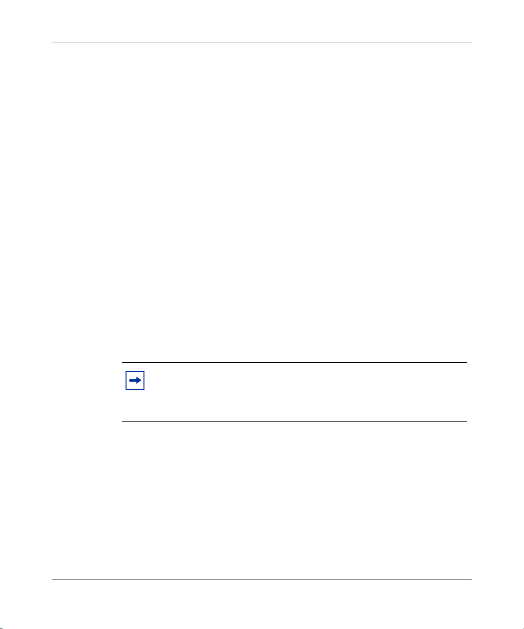
Figure 30 EAPOL Security Configuration page (1 of 2) . . . . . . . . . . . . . . . . . . . . . . 92
Figure 31 EAPOL Security Configuration page (2 of 2) . . . . . . . . . . . . . . . . . . . . . . 92
Figure 32 Remote Access page . . . . . . . . . . . . . . . . . . . . . . . . . . . . . . . . . . . . . . . . 95
Figure 33 Security Configuration page . . . . . . . . . . . . . . . . . . . . . . . . . . . . . . . . . . . 98
Figure 34 Port Lists page . . . . . . . . . . . . . . . . . . . . . . . . . . . . . . . . . . . . . . . . . . . . 100
Figure 35 Port List View, Port List page . . . . . . . . . . . . . . . . . . . . . . . . . . . . . . . . . 101
Figure 36 Port List View, Learn by Ports page . . . . . . . . . . . . . . . . . . . . . . . . . . . . 101
Figure 37 Security Table page . . . . . . . . . . . . . . . . . . . . . . . . . . . . . . . . . . . . . . . . 102
Figure 38 Port List View, Clear by Ports page . . . . . . . . . . . . . . . . . . . . . . . . . . . . 104
Figure 39 Port Configuration page . . . . . . . . . . . . . . . . . . . . . . . . . . . . . . . . . . . . . 105
Figure 40 DA MAC Filtering page . . . . . . . . . . . . . . . . . . . . . . . . . . . . . . . . . . . . . . 106
Figure 41 MAC Address Table page . . . . . . . . . . . . . . . . . . . . . . . . . . . . . . . . . . . . 108
Figure 42 Find MAC Address Table page . . . . . . . . . . . . . . . . . . . . . . . . . . . . . . . . 110
Figure 43 Port Management page . . . . . . . . . . . . . . . . . . . . . . . . . . . . . . . . . . . . . 112
Figure 44 High Speed Flow Control page . . . . . . . . . . . . . . . . . . . . . . . . . . . . . . . . 115
Figure 45 Software Download page for a Pure BPS 2000 stack . . . . . . . . . . . . . . 116
Figure 46 Software Download page for a Hybrid stack . . . . . . . . . . . . . . . . . . . . . . 117
Figure 47 Configuration File Download/Upload page . . . . . . . . . . . . . . . . . . . . . . . 124
Figure 48 Console/Communication Port page . . . . . . . . . . . . . . . . . . . . . . . . . . . . 127
Figure 49 Stack Operational Mode page . . . . . . . . . . . . . . . . . . . . . . . . . . . . . . . . 128
Figure 50 RMON Threshold page . . . . . . . . . . . . . . . . . . . . . . . . . . . . . . . . . . . . . . 130
Figure 51 RMON Event Log page . . . . . . . . . . . . . . . . . . . . . . . . . . . . . . . . . . . . . 133
Figure 52 System Log page . . . . . . . . . . . . . . . . . . . . . . . . . . . . . . . . . . . . . . . . . . 134
Figure 53 RMON Ethernet page . . . . . . . . . . . . . . . . . . . . . . . . . . . . . . . . . . . . . . . 136
Figure 54 RMON Ethernet: Chart in a bar graph format . . . . . . . . . . . . . . . . . . . . . 138
Figure 55 RMON Ethernet: Chart in a pie chart format . . . . . . . . . . . . . . . . . . . . . . 139
Figure 56 RMON History page . . . . . . . . . . . . . . . . . . . . . . . . . . . . . . . . . . . . . . . . 140
Figure 57 Port page . . . . . . . . . . . . . . . . . . . . . . . . . . . . . . . . . . . . . . . . . . . . . . . . 144
Figure 58 Port: Chart page in a pie chart format . . . . . . . . . . . . . . . . . . . . . . . . . . 147
Figure 59 Port: Chart page in a bar graph format . . . . . . . . . . . . . . . . . . . . . . . . . . 148
Figure 60 Port Error Summary page . . . . . . . . . . . . . . . . . . . . . . . . . . . . . . . . . . . . 149
Figure 61 Interface page . . . . . . . . . . . . . . . . . . . . . . . . . . . . . . . . . . . . . . . . . . . . . 150
Figure 62 Interface: Chart in a pie chart format . . . . . . . . . . . . . . . . . . . . . . . . . . . 152
Figure 63 Interface: Chart in a bar graph format . . . . . . . . . . . . . . . . . . . . . . . . . . 153
Figure 64 Ethernet Errors page . . . . . . . . . . . . . . . . . . . . . . . . . . . . . . . . . . . . . . . 154
209570-C
Page 17

Figures 17
Figure 65 Ethernet Error: Chart in a pie chart format . . . . . . . . . . . . . . . . . . . . . . . 156
Figure 66 Ethernet Error: Chart in a bar graph format . . . . . . . . . . . . . . . . . . . . . . 157
Figure 67 Transparent Bridging page . . . . . . . . . . . . . . . . . . . . . . . . . . . . . . . . . . . 158
Figure 68 Transparent Bridging: Chart in a pie chart format . . . . . . . . . . . . . . . . . . 159
Figure 69 Transparent Bridging: Chart in a bar graph format . . . . . . . . . . . . . . . . . 160
Figure 70 Port Mirroring page . . . . . . . . . . . . . . . . . . . . . . . . . . . . . . . . . . . . . . . . . 162
Figure 71 Rate Limiting page . . . . . . . . . . . . . . . . . . . . . . . . . . . . . . . . . . . . . . . . . 165
Figure 72 IGMP Configuration page . . . . . . . . . . . . . . . . . . . . . . . . . . . . . . . . . . . . 167
Figure 73 IGMP: VLAN Configuration page . . . . . . . . . . . . . . . . . . . . . . . . . . . . . . 168
Figure 74 IGMP Multicast Group Membership page . . . . . . . . . . . . . . . . . . . . . . . . 170
Figure 75 VLAN Configuration page . . . . . . . . . . . . . . . . . . . . . . . . . . . . . . . . . . . . 173
Figure 76 VLAN Configuration: Port Based setting page . . . . . . . . . . . . . . . . . . . . 175
Figure 77 VLAN Configuration: Port Based modification page . . . . . . . . . . . . . . . . 176
Figure 78 VLAN Configuration: Protocol Based setting page . . . . . . . . . . . . . . . . . 178
Figure 79 VLAN Configuration: Protocol Based modification page . . . . . . . . . . . . 182
Figure 80 VLAN Configuration: MAC SA Based setting page . . . . . . . . . . . . . . . . 184
Figure 81 VLAN Configuration: MAC SA Based modification page . . . . . . . . . . . . 185
Figure 82 VLAN Configuration: MAC Address page . . . . . . . . . . . . . . . . . . . . . . . . 186
Figure 83 Port Configuration page . . . . . . . . . . . . . . . . . . . . . . . . . . . . . . . . . . . . . 189
Figure 84 Port Information page . . . . . . . . . . . . . . . . . . . . . . . . . . . . . . . . . . . . . . . 191
Figure 85 Spanning Tree Group Configuration page . . . . . . . . . . . . . . . . . . . . . . . 193
Figure 86 Spanning Tree VLAN Membership page . . . . . . . . . . . . . . . . . . . . . . . . 195
Figure 87 Spanning Tree Add VLAN page . . . . . . . . . . . . . . . . . . . . . . . . . . . . . . . 196
Figure 88 Spanning Tree Remove VLAN page . . . . . . . . . . . . . . . . . . . . . . . . . . . 196
Figure 89 Spanning Tree Port Configuration page . . . . . . . . . . . . . . . . . . . . . . . . . 197
Figure 90 Spanning Tree Bridge Information page . . . . . . . . . . . . . . . . . . . . . . . . . 199
Figure 91 Group page . . . . . . . . . . . . . . . . . . . . . . . . . . . . . . . . . . . . . . . . . . . . . . . 203
Figure 92 Utilization page . . . . . . . . . . . . . . . . . . . . . . . . . . . . . . . . . . . . . . . . . . . . 205
Figure 93 QoS Wizard opening page . . . . . . . . . . . . . . . . . . . . . . . . . . . . . . . . . . . 209
Figure 94 Packet prioritization selection page . . . . . . . . . . . . . . . . . . . . . . . . . . . . 209
Figure 95 Standard prioritization page . . . . . . . . . . . . . . . . . . . . . . . . . . . . . . . . . . 210
Figure 96 Session confirmation page . . . . . . . . . . . . . . . . . . . . . . . . . . . . . . . . . . . 210
Figure 97 QoS Policies to Configure window . . . . . . . . . . . . . . . . . . . . . . . . . . . . . 212
Figure 98 Packet prioritization explanation page . . . . . . . . . . . . . . . . . . . . . . . . . . 213
Figure 99 VLAN prioritization selection page . . . . . . . . . . . . . . . . . . . . . . . . . . . . . 214
Using Web-based Management for the Business Policy Switch 2000 Software Version 2.0
Page 18

18 Figures
Figure 100 Meter for VLAN page . . . . . . . . . . . . . . . . . . . . . . . . . . . . . . . . . . . . . . . 214
Figure 101 Meter setting for VLAN page . . . . . . . . . . . . . . . . . . . . . . . . . . . . . . . . . 215
Figure 102 Service Class selection for VLAN page . . . . . . . . . . . . . . . . . . . . . . . . . 216
Figure 103 Shaper for VLAN page . . . . . . . . . . . . . . . . . . . . . . . . . . . . . . . . . . . . . . 217
Figure 104 Setting shaping parameters for VLAN page . . . . . . . . . . . . . . . . . . . . . . 218
Figure 105 Additional VLANs page . . . . . . . . . . . . . . . . . . . . . . . . . . . . . . . . . . . . . . 219
Figure 106 Packet prioritization page with prioritized VLAN(s) . . . . . . . . . . . . . . . . . 220
Figure 107 QoS Policies to Configure window with VLAN entry . . . . . . . . . . . . . . . . 220
Figure 108 IP Application prioritization page . . . . . . . . . . . . . . . . . . . . . . . . . . . . . . 221
Figure 109 Meter for IP Application page . . . . . . . . . . . . . . . . . . . . . . . . . . . . . . . . . 221
Figure 110 Meter setting for IP Application page . . . . . . . . . . . . . . . . . . . . . . . . . . . 222
Figure 111 Service Class selection for IP Application page . . . . . . . . . . . . . . . . . . . 223
Figure 112 Shaper for IP Application page . . . . . . . . . . . . . . . . . . . . . . . . . . . . . . . . 224
Figure 113 Setting shaping parameters for IP Application page . . . . . . . . . . . . . . . 225
Figure 114 Packet prioritization page with prioritized IP Application(s) . . . . . . . . . . 226
Figure 115 QoS Policies to Configure window with IP Application entry . . . . . . . . . 226
Figure 116 Policy label page . . . . . . . . . . . . . . . . . . . . . . . . . . . . . . . . . . . . . . . . . . 227
Figure 117 Policy definition page . . . . . . . . . . . . . . . . . . . . . . . . . . . . . . . . . . . . . . . 227
Figure 118 IP classification rules page (1 of 2) . . . . . . . . . . . . . . . . . . . . . . . . . . . . . 228
Figure 119 IP classification rules page (2 of 2) . . . . . . . . . . . . . . . . . . . . . . . . . . . . . 228
Figure 120 Layer 2 classification rules page (1 of 2) . . . . . . . . . . . . . . . . . . . . . . . . 229
Figure 121 Layer 2 classification rules page (2 of 2) . . . . . . . . . . . . . . . . . . . . . . . . 230
Figure 122 Meter for user defined flow page . . . . . . . . . . . . . . . . . . . . . . . . . . . . . . 231
Figure 123 Meter setting for user defined flow page . . . . . . . . . . . . . . . . . . . . . . . . 231
Figure 124 Service Class selection for user defined flow page . . . . . . . . . . . . . . . . 232
Figure 125 Shaper for user defined flow page . . . . . . . . . . . . . . . . . . . . . . . . . . . . . 233
Figure 126 Setting shaping parameters for user defined flow page . . . . . . . . . . . . . 234
Figure 127 Additional user defined flows page . . . . . . . . . . . . . . . . . . . . . . . . . . . . . 235
Figure 128 Packet prioritization page with prioritized User Defined Flow(s) . . . . . . . 236
Figure 129 QoS Policies to Configure window with user defined flow entry . . . . . . . 236
Figure 130 QoS Quick Config Interface Group page—View Interface Group . . . . . . 237
Figure 131 QoS Quick Config Interface Group page—Create Interface Group . . . . 238
Figure 132 QoS Quick Config Interface Group page—View Interface Group . . . . . . 239
Figure 133 QoS Quick Config Policy page (1 of 3) . . . . . . . . . . . . . . . . . . . . . . . . . . 240
Figure 134 QoS Quick Config Policy page (2 of 3) . . . . . . . . . . . . . . . . . . . . . . . . . . 240
209570-C
Page 19

Figures 19
Figure 135 QoS Quick Config Policy page (3 of 3) . . . . . . . . . . . . . . . . . . . . . . . . . . 241
Figure 136 QoS Quick Config page for configuring IP filters page (1 of 2) . . . . . . . . 242
Figure 137 QoS Quick Config page for configuring IP filters page (2 of 2) . . . . . . . . 242
Figure 138 QoS Quick Config page for configuring layer 2 filters page (1 of 2) . . . . 244
Figure 139 QoS Quick Config page for configuring layer 2 filters page (2 of 2) . . . . 244
Figure 140 QoS Quick Config page with existing filter group choice . . . . . . . . . . . . 246
Figure 141 QoS Quick Config Policy page with displayed filter group . . . . . . . . . . . 247
Figure 142 QoS Quick Config Policy page with expanded meter area . . . . . . . . . . . 248
Figure 143 Step 3: Shaper . . . . . . . . . . . . . . . . . . . . . . . . . . . . . . . . . . . . . . . . . . . . 249
Figure 144 Shaper box . . . . . . . . . . . . . . . . . . . . . . . . . . . . . . . . . . . . . . . . . . . . . . . 249
Figure 145 Policy area of QoS Quick Config Policy page . . . . . . . . . . . . . . . . . . . . . 251
Figure 146 QoS Advanced Policies page with configured policies (1 of 2) . . . . . . . . 252
Figure 147 QoS Advanced Policies page with configured policies (2 of 2) . . . . . . . . 252
Figure 148 QoS Advanced Interface Configuration page . . . . . . . . . . . . . . . . . . . . . 255
Figure 149 Interface ID page . . . . . . . . . . . . . . . . . . . . . . . . . . . . . . . . . . . . . . . . . . 258
Figure 150 Interface Group Assignment page . . . . . . . . . . . . . . . . . . . . . . . . . . . . . 259
Figure 151 802.1p Priority Queue Assignment page . . . . . . . . . . . . . . . . . . . . . . . . 262
Figure 152 802.1p Priority Mapping page . . . . . . . . . . . . . . . . . . . . . . . . . . . . . . . . . 263
Figure 153 DSCP Queue Assignment page . . . . . . . . . . . . . . . . . . . . . . . . . . . . . . . 264
Figure 154 DSCP Mapping Table page . . . . . . . . . . . . . . . . . . . . . . . . . . . . . . . . . . 266
Figure 155 DSCP Mapping Modification page . . . . . . . . . . . . . . . . . . . . . . . . . . . . . 267
Figure 156 IP Classification page (1 of 3) . . . . . . . . . . . . . . . . . . . . . . . . . . . . . . . . . 268
Figure 157 IP Classification page (2 of 3) . . . . . . . . . . . . . . . . . . . . . . . . . . . . . . . . . 269
Figure 158 IP Classification page (3 of 3) . . . . . . . . . . . . . . . . . . . . . . . . . . . . . . . . . 269
Figure 159 IP Classification Group page . . . . . . . . . . . . . . . . . . . . . . . . . . . . . . . . . 274
Figure 160 Layer2 Classification page (1 of 2) . . . . . . . . . . . . . . . . . . . . . . . . . . . . . 278
Figure 161 Layer2 Classification page (2 of 2) . . . . . . . . . . . . . . . . . . . . . . . . . . . . . 279
Figure 162 Layer2 Group page . . . . . . . . . . . . . . . . . . . . . . . . . . . . . . . . . . . . . . . . . 285
Figure 163 Layer2 Group modification page . . . . . . . . . . . . . . . . . . . . . . . . . . . . . . 286
Figure 164 Action page . . . . . . . . . . . . . . . . . . . . . . . . . . . . . . . . . . . . . . . . . . . . . . . 289
Figure 165 QoS Advanced Meter page . . . . . . . . . . . . . . . . . . . . . . . . . . . . . . . . . . 292
Figure 166 QoS Advanced Shapers page . . . . . . . . . . . . . . . . . . . . . . . . . . . . . . . . 295
Figure 167 QoS Advanced Policies page (1 of 3) . . . . . . . . . . . . . . . . . . . . . . . . . . . 298
Figure 168 QoS Advanced Policies page (2 of 3) . . . . . . . . . . . . . . . . . . . . . . . . . . . 299
Figure 169 QoS Advanced Policies page (3 of 3) . . . . . . . . . . . . . . . . . . . . . . . . . . . 299
Using Web-based Management for the Business Policy Switch 2000 Software Version 2.0
Page 20

20 Figures
Figure 170 Policy Statistics page . . . . . . . . . . . . . . . . . . . . . . . . . . . . . . . . . . . . . . . 302
Figure 171 Agent page (1 of 2) . . . . . . . . . . . . . . . . . . . . . . . . . . . . . . . . . . . . . . . . . 304
Figure 172 Agent page (2 of 2) . . . . . . . . . . . . . . . . . . . . . . . . . . . . . . . . . . . . . . . . . 305
Figure 173 Status page . . . . . . . . . . . . . . . . . . . . . . . . . . . . . . . . . . . . . . . . . . . . . . 308
Figure 174 Configuration page . . . . . . . . . . . . . . . . . . . . . . . . . . . . . . . . . . . . . . . . . 312
Figure 175 Online help window . . . . . . . . . . . . . . . . . . . . . . . . . . . . . . . . . . . . . . . . 316
Figure 176 Nortel Networks Technical Documentation Web site . . . . . . . . . . . . . . . 317
Figure 177 Nortel Networks Customer Support Web site . . . . . . . . . . . . . . . . . . . . . 318
209570-C
Page 21

Tables
Table 1 Main headings and options . . . . . . . . . . . . . . . . . . . . . . . . . . . . . . . . . . . . 37
Table 2 Menu icons . . . . . . . . . . . . . . . . . . . . . . . . . . . . . . . . . . . . . . . . . . . . . . . . 38
Table 3 Page buttons and icons . . . . . . . . . . . . . . . . . . . . . . . . . . . . . . . . . . . . . . 40
Table 4 System Information page items . . . . . . . . . . . . . . . . . . . . . . . . . . . . . . . . 43
Table 5 CPU/Memory Utilization page items . . . . . . . . . . . . . . . . . . . . . . . . . . . . . 44
Table 6 Console page items . . . . . . . . . . . . . . . . . . . . . . . . . . . . . . . . . . . . . . . . . 45
Table 7 RADIUS page items . . . . . . . . . . . . . . . . . . . . . . . . . . . . . . . . . . . . . . . . . 46
Table 8 User levels and access levels . . . . . . . . . . . . . . . . . . . . . . . . . . . . . . . . . 48
Table 9 Stack Information page fields . . . . . . . . . . . . . . . . . . . . . . . . . . . . . . . . . 54
Table 10 Switch Information page fields . . . . . . . . . . . . . . . . . . . . . . . . . . . . . . . . . 56
Table 11 BPS 2000 switch LED descriptions . . . . . . . . . . . . . . . . . . . . . . . . . . . . . 58
Table 12 Stack Numbering Setting page fields . . . . . . . . . . . . . . . . . . . . . . . . . . . 60
Table 13 IP page items . . . . . . . . . . . . . . . . . . . . . . . . . . . . . . . . . . . . . . . . . . . . . . 65
Table 14 System page items . . . . . . . . . . . . . . . . . . . . . . . . . . . . . . . . . . . . . . . . . . 68
Table 15 SNMPv1 page items . . . . . . . . . . . . . . . . . . . . . . . . . . . . . . . . . . . . . . . . . 70
Table 16 System Information section fields . . . . . . . . . . . . . . . . . . . . . . . . . . . . . . . 71
Table 17 SNMPv3 Counters section fields . . . . . . . . . . . . . . . . . . . . . . . . . . . . . . . 72
Table 18 User Specification Table section items . . . . . . . . . . . . . . . . . . . . . . . . . . . 73
Table 19 User Specification Creation section items . . . . . . . . . . . . . . . . . . . . . . . . 74
Table 20 Group Membership page items . . . . . . . . . . . . . . . . . . . . . . . . . . . . . . . . 76
Table 21 Group Access Rights page items . . . . . . . . . . . . . . . . . . . . . . . . . . . . . . . 79
Table 22 Management Information View page items . . . . . . . . . . . . . . . . . . . . . . . 81
Table 23 Notification page items . . . . . . . . . . . . . . . . . . . . . . . . . . . . . . . . . . . . . . . 83
Table 24 Target Address page items . . . . . . . . . . . . . . . . . . . . . . . . . . . . . . . . . . . . 86
Table 25 Target Parameter page items . . . . . . . . . . . . . . . . . . . . . . . . . . . . . . . . . . 88
Table 26 SNMP Trap Receiver page items . . . . . . . . . . . . . . . . . . . . . . . . . . . . . . . 90
Table 27 EAPOL Security Configuration page fields . . . . . . . . . . . . . . . . . . . . . . . 93
Table 28 Remote Access page fields . . . . . . . . . . . . . . . . . . . . . . . . . . . . . . . . . . . 95
Table 29 Security Configuration page items . . . . . . . . . . . . . . . . . . . . . . . . . . . . . . 98
21
Using Web-based Management for the Business Policy Switch 2000 Software Version 2.0
Page 22

22 Tables
Table 30 Ports Lists page items . . . . . . . . . . . . . . . . . . . . . . . . . . . . . . . . . . . . . . 100
Table 31 Security Table page items . . . . . . . . . . . . . . . . . . . . . . . . . . . . . . . . . . . 103
Table 32 Port Configuration page items . . . . . . . . . . . . . . . . . . . . . . . . . . . . . . . . 105
Table 33 DA MAC Filtering page items . . . . . . . . . . . . . . . . . . . . . . . . . . . . . . . . . 106
Table 34 MAC Address Table page items . . . . . . . . . . . . . . . . . . . . . . . . . . . . . . . 109
Table 35 Port Management page items . . . . . . . . . . . . . . . . . . . . . . . . . . . . . . . . 113
Table 36 High Speed Flow Control page items . . . . . . . . . . . . . . . . . . . . . . . . . . . 115
Table 37 Software Download page items . . . . . . . . . . . . . . . . . . . . . . . . . . . . . . . 117
Table 38 LED Indications during the software download process . . . . . . . . . . . . 118
Table 39 Configuration File page items . . . . . . . . . . . . . . . . . . . . . . . . . . . . . . . . . 125
Table 40 Requirements for storing or retrieving configuration parameters on a
Table 41 Parameters not saved to the configuration file . . . . . . . . . . . . . . . . . . . . 126
Table 42 Console/Communication Port Setting page items . . . . . . . . . . . . . . . . . 127
Table 43 Stack Operational Mode page items . . . . . . . . . . . . . . . . . . . . . . . . . . . 128
Table 44 RMON Threshold page items . . . . . . . . . . . . . . . . . . . . . . . . . . . . . . . . 131
Table 45 RMON Event Log page fields . . . . . . . . . . . . . . . . . . . . . . . . . . . . . . . . . 134
Table 46 System Log page fields . . . . . . . . . . . . . . . . . . . . . . . . . . . . . . . . . . . . . 135
Table 47 RMON Ethernet page items . . . . . . . . . . . . . . . . . . . . . . . . . . . . . . . . . 136
Table 48 RMON History page items . . . . . . . . . . . . . . . . . . . . . . . . . . . . . . . . . . . 141
Table 49 Port page items . . . . . . . . . . . . . . . . . . . . . . . . . . . . . . . . . . . . . . . . . . . 144
Table 50 Port Error Summary Table fields . . . . . . . . . . . . . . . . . . . . . . . . . . . . . . 149
Table 51 Interface page items . . . . . . . . . . . . . . . . . . . . . . . . . . . . . . . . . . . . . . . 151
Table 52 Ethernet Errors page items . . . . . . . . . . . . . . . . . . . . . . . . . . . . . . . . . . 154
Table 53 Transparent Bridging page items . . . . . . . . . . . . . . . . . . . . . . . . . . . . . . 158
Table 54 Port Mirroring page items . . . . . . . . . . . . . . . . . . . . . . . . . . . . . . . . . . . 163
Table 55 Port-based monitoring modes . . . . . . . . . . . . . . . . . . . . . . . . . . . . . . . . 164
Table 56 Address-based monitoring modes . . . . . . . . . . . . . . . . . . . . . . . . . . . . . 164
Table 57 Rate Limiting page items . . . . . . . . . . . . . . . . . . . . . . . . . . . . . . . . . . . . 166
Table 58 IGMP Configuration page items . . . . . . . . . . . . . . . . . . . . . . . . . . . . . . . 167
Table 59 IGMP: VLAN Configuration page items . . . . . . . . . . . . . . . . . . . . . . . . . 168
Table 60 IGMP Multicast Group Membership page items . . . . . . . . . . . . . . . . . . . 170
Table 61 VLAN Configuration page items . . . . . . . . . . . . . . . . . . . . . . . . . . . . . . . 174
Table 62 VLAN Configuration: Port Based setting page items . . . . . . . . . . . . . . . 175
Table 63 VLAN Configuration: Port Based modification page items . . . . . . . . . . . 177
TFTP server . . . . . . . . . . . . . . . . . . . . . . . . . . . . . . . . . . . . . . . . . . . . . . 126
209570-C
Page 23

Tables 23
Table 64 VLAN Configuration: Protocol Based setting page items . . . . . . . . . . . . 179
Table 65 Standard protocol-based VLANs and PID types . . . . . . . . . . . . . . . . . . 180
Table 66 Predefined Protocol Identifier (PID) . . . . . . . . . . . . . . . . . . . . . . . . . . . . 181
Table 67 VLAN Configuration: Protocol Based modification page items . . . . . . . . 183
Table 68 VLAN Configuration: MAC SA Based setting page items . . . . . . . . . . . . 184
Table 69 VLAN Configuration: MAC SA Based modification page items . . . . . . . 186
Table 70 Port Configuration page items . . . . . . . . . . . . . . . . . . . . . . . . . . . . . . . . 189
Table 71 Port Information page items . . . . . . . . . . . . . . . . . . . . . . . . . . . . . . . . . . 191
Table 72 Spanning Tree Group Configuration page items . . . . . . . . . . . . . . . . . . 193
Table 73 Spanning Tree Port Configuration page items . . . . . . . . . . . . . . . . . . . . 198
Table 74 Spanning Tree Bridge Information page items . . . . . . . . . . . . . . . . . . . . 200
Table 75 Group page items . . . . . . . . . . . . . . . . . . . . . . . . . . . . . . . . . . . . . . . . . . 204
Table 76 Utilization page items . . . . . . . . . . . . . . . . . . . . . . . . . . . . . . . . . . . . . . 205
Table 77 QoS Interface Queue Table section items . . . . . . . . . . . . . . . . . . . . . . . 255
Table 78 Interface Group Table section items . . . . . . . . . . . . . . . . . . . . . . . . . . . . 256
Table 79 Interface Group Creation section page items . . . . . . . . . . . . . . . . . . . . . 257
Table 80 Interface ID page items . . . . . . . . . . . . . . . . . . . . . . . . . . . . . . . . . . . . . 258
Table 81 Interface Group Assignment page items . . . . . . . . . . . . . . . . . . . . . . . . 259
Table 82 802.1p Priority Assignment Table section page items . . . . . . . . . . . . . . 262
Table 83 802.1p Priority Mapping page items . . . . . . . . . . . . . . . . . . . . . . . . . . . . 264
Table 84 DSCP Queue Assignment page items . . . . . . . . . . . . . . . . . . . . . . . . . . 265
Table 85 DSCP Mapping Table page items . . . . . . . . . . . . . . . . . . . . . . . . . . . . . 266
Table 86 DSCP Mapping Modification page items . . . . . . . . . . . . . . . . . . . . . . . . 267
Table 87 IP Filter Table and Filter Creation sections page items . . . . . . . . . . . . . 270
Table 88 IP Filter Group section page items . . . . . . . . . . . . . . . . . . . . . . . . . . . . . 273
Table 89 IP Classification Group page items . . . . . . . . . . . . . . . . . . . . . . . . . . . . 274
Table 90 IP Modification Group page items . . . . . . . . . . . . . . . . . . . . . . . . . . . . . 276
Table 91 Layer2 Filter Table and Layer2 Filter Creation section items . . . . . . . . . 279
Table 92 IP Filter Group Table section items . . . . . . . . . . . . . . . . . . . . . . . . . . . . . 284
Table 93 Layer2 Group page items . . . . . . . . . . . . . . . . . . . . . . . . . . . . . . . . . . . . 285
Table 94 Layer2 Group modification page items . . . . . . . . . . . . . . . . . . . . . . . . . . 287
Table 95 Action page items . . . . . . . . . . . . . . . . . . . . . . . . . . . . . . . . . . . . . . . . . 289
Table 96 Meter Creation fields . . . . . . . . . . . . . . . . . . . . . . . . . . . . . . . . . . . . . . . 292
Table 97 Meter Table fields . . . . . . . . . . . . . . . . . . . . . . . . . . . . . . . . . . . . . . . . . 293
Table 98 Shaper Creation fields . . . . . . . . . . . . . . . . . . . . . . . . . . . . . . . . . . . . . . 295
Using Web-based Management for the Business Policy Switch 2000 Software Version 2.0
Page 24

24 Tables
Table 99 Shaper Table fields . . . . . . . . . . . . . . . . . . . . . . . . . . . . . . . . . . . . . . . . 296
Table 100 Policy page items . . . . . . . . . . . . . . . . . . . . . . . . . . . . . . . . . . . . . . . . . . 300
Table 101 Policy Statistics page items . . . . . . . . . . . . . . . . . . . . . . . . . . . . . . . . . . 302
Table 102 Agent page items . . . . . . . . . . . . . . . . . . . . . . . . . . . . . . . . . . . . . . . . . . 305
Table 103 Status page items . . . . . . . . . . . . . . . . . . . . . . . . . . . . . . . . . . . . . . . . . 308
Table 104 COPS Configuration Table section items . . . . . . . . . . . . . . . . . . . . . . . . 312
209570-C
Page 25

Preface
25
Welcom e to Using Web-based Management for the Business Policy Switch 2000
Software Version 2.0. This document provides instructions on configuring and
managing the Business Policy Switch 2000* through the World Wide Web.
The Web-based management interface is one of many tools specifically designed
to assist the network manager in creating complex standalone or network
configurations. In addition to the Web-based management system discussed in this
book, you can manage the BPS 2000 using SNMP, the Command Line Interface
(CLI), Device Manager (DM), or the console interface (CI) menus. Refer to the
documents listed “Related publications” on page 26 for information on using and
managing the BPS 2000.
This guide describes how to use the Web-based management user interface to
configure and maintain your BPS 2000 and the devices connected within its
framework.
Before you begin
This guide is intended for network managers who are responsible for configuring
BPS 2000. Consequently, this guide assumes prior knowledge and understanding
of the terminology, theories, and practices and specific knowledge about the
networking devices, protocols, and interfaces that comprise your network.
You should have working knowledge of the Windows
graphical user interfaces (GUIs), and Web browsers.
Using Web-based Management for the Business Policy Switch 2000 Software Version 2.0
*
operating system,
Page 26

26
Text conventions
This guide uses the following text conventions:
italic text Indicates new terms and book titles.
separator ( > ) Shows menu paths.
Related publications
For more information about using the Web-based management user interface and
the BPS 2000, refer to the following publications:
Example: Configuration > Port Management
identifies the Port Management option on the
Configuration menu.
• Release Notes for the Business Policy Switch 2000 Software Version 2.0 (part
number 210676-F)
Documents important changes about the software and hardware that are not
covered in other related publications.
• Using the Business Policy Switch 2000 Software Version 2.0 (part number
208700-C)
Describes how to use the BPS 2000.
• Business Policy Switch 2000 Installation Instructions (part number
209319-A)
Describes how to install the BPS 2000.
• Reference for the Business Policy Switch 2000 Command Line Interface
Software Version 2.0 (part number 212160-B)
Describes how to use the Command Line Interface (CLI) to configure and
manage the BPS 2000.
• Reference for the Business Policy Switch 2000 Management Software Version
2.0 (part number 209322-C)
209570-C
Page 27

27
Describes how to use the Java Device Manager to configure and manage the
BPS 2000.
• Installing Media Dependent Adapters (MDA)s (part number 302403-H)
Describes how to install optional MDAs in your Business Policy Switch 2000.
• Installing Gigabit Interface Converters and Small Form Factor Pluggable
Interface Converters (part number 312865-B)
Describes how to install optional GBICs and SFP GBICs into the optional
MDA in your Business Policy Switch 2000.
• Installing Optivity Policy Services (part number 306972-E Rev 00)
Describes how to install Optivity Policy Services*.
• Managing Policy Information in Optivity Policy Services
(part number 306969-F Rev 00)
Describes how to configure and manage Optivity Policy Services.
• Release Notes for Optivity Policy Services Version 2.0.1
(part number 306975-F Rev 00)
Documents important Optivity Policy Services changes that are not covered in
other related publications.
• Task Map - Installing Optivity Policy Services Product Family
(part number 306976-E Rev 00)
Provides a quick map to installing Optivity Policy Services.
• Known Anomalies for Optivity Policy Services Version 2.0
(part number 306974-E Rev 00)
Describes known anomalies with Optivity Policy Services.
You can print selected technical manuals and release notes free, directly from the
Internet. Go to the www.nortelnetworks.com/documentation URL. (The product
family for the BPS 2000 is Data and Internet.) Find the product for which you
need documentation. Then locate the specific category and model or version for
your hardware or software product. Use Adobe* Acrobat Reader* to open the
manuals and release notes, search for the sections you need, and print them on
most standard printers. Go to Adobe Systems at the www.adobe.com URL to
download a free copy of the Adobe Acrobat Reader.
Using Web-based Management for the Business Policy Switch 2000 Software Version 2.0
Page 28

28
Additionally, you can obtain printed books from Fatbrain.com. Contact
Fatbrain.com to order a printed book at http://www1.fatbrain.com/documentation/
nortel.
How to get help
If you purchased a service contract for your Nortel Networks product from a
distributor or authorized reseller, contact the technical support staff for that
distributor or reseller for assistance.
If you purchased a Nortel Networks service program, contact one of the following
Nortel Networks Technical Solutions Centers:
Technical Solutions Center Telephone
Europe, Middle East, and Africa (33) (4) 92-966-968
North America (800) 4NORTEL or (800) 466-7835
Asia Pacific (61) (2) 9927-8800
China (800) 810-5000
209570-C
Additional information about the Nortel Networks Technical Solutions Centers is
available from the www.nortelnetworks.com/help/contact/global URL.
An Express Routing Code (ERC) is available for many Nortel Networks products
and services. When you use an ERC, your call is routed to a technical support
person who specializes in supporting that product or service.
your product or service, go to the
eserv/common/essContactUs.jsp
http://www130.nortelnetworks.com/cgi-bin/
URL.
To locate an ERC for
Page 29

Chapter 1
Using the Web-based management interface
This chapter describes the requirements for using the Web-based management
interface and how to use it as a tool to configure your BPS 2000. This chapter
covers:
• “New features,” next
• “Stacking compatibility” on page 30
• “Software version 2.0 compatibility with BayStack 450 switches” on page 32
• “Requirements” on page 33
• “Port numbering syntax” on page 33
• “Logging in to the Web-based management interface” on page 34
• “Web page layout” on page 35
29
New features
The following new features that you can access through Web-based management
have been introduced to the BPS 2000 software since version 1.0:
• Introduced with software version 2.0
— Support for BPS 2000-1GT, BPS 2000-2GT, and BPS 2000-2GE MDAs
— Ability to view CPU and memory utilization (refer to Chapter 2)
— Ability to set per port spanning tree path cost and priority (refer to
— Shaping for QoS networks (refer to Chapters 8 and 9)
— Improved QoS Wizard (refer to Chapter 8)
Using Web-based Management for the Business Policy Switch 2000 Software Version 2.0
(refer to Installing Media Dependent Adapters (MDA)s and Installing
Gigabit Interface Converters and Small Form Factor Pluggable Interface
Converters)
Chapter 7)
Page 30
30 Using the Web-based management interface
— QoS Quick Config (refer to Chapter 8)
— Port naming (refer to Chapter 4)
— MAC address-based filtering (refer to Chapter 4)
— Individual IP addresses for each unit in the stack (refer to Chapter 4)
— Configurable VID for tagged BPDU with multiple spanning tree groups
(refer to Chapter 7)
— Specifying multiple VLANs in a QoS single filter (refer to Chapters 8 and
9)
• Introduced with software version 1.2
— VLANS increased to 256
— Support for multiple spanning tree groups (refer to Chapter 7)
— IP manager list (refer to Chapter 4)
• Introduced with software version 1.1
— QoS metering added to policy-enabled networks (refer to Chapter 8)
— Support for the BayStack 450-1GBIC MDA
— EAPOL-based security (refer to Chapter 4)
— Automatic PVID (refer to Chapter 5)
— Table of port statistics (refer to Chapter 6)
Note: To access the software version 2.0 features in a mixed stack, you
must access a BPS 2000 unit. Additionally:
- only 64 VLANS are available in a mixed stack
- multiple STG support is not available in a mixed stack
Stacking compatibility
You can stack the BPS 2000 up to 8 units high. There are two types of stacks:
• Pure BPS 2000—This stack has only BPS 2000 switches. It is sometimes
referred to as a pure stack. The stack operational mode for this type of stack is
Pure BPS 2000 Mode.
209570-C
Page 31

Using the Web-based management interface 31
• Hybrid—This stack has a combination of BPS 2000 switches and BayStack*
450 and/or BayStack 410 switches. It is sometimes referred to as a mixed
stack. The stack operational mode for this type of stack is Hybrid Mode.
When you work with the BPS 2000 in standalone mode, you should ensure that
the stack operational mode shows Pure BPS 2000 Mode, and does not show
Hybrid Mode.
All BPS 2000 switches in the stack must be running the identical version of
software, and all the BayStack switches must be running the identical version of
software.
When you are working with a mixed stack, you must ensure that the
Interoperability Software Version Numbers (ISVN) are identical. That is, the
ISVN number for the BayStack 450 switch and BayStack 410 switch must have
the same ISVN as the BPS 2000. If the ISVNs are not the same, the stack does not
operate.
In sum, the stacking software compatibility requirements are as follows:
• Pure BPS 2000 stack—All units must be running the same software version.
• Pure BayStack 450 stack—All units must be running the same software
version.
• Hybrid stack:
— All BPS 2000 units must be running the same software version.
— All BayStack 410 units must be running the same software version.
— All BayStack 450 units must be running the same software version.
— All software versions must have the identical ISVN.
Refer to Appendix B of Using the Business Policy Switch 2000 Software Version
2.0 for complete information on interoperability and compatibility between the
BPS 2000 and BayStack switches.
Using Web-based Management for the Business Policy Switch 2000 Software Version 2.0
Page 32

32 Using the Web-based management interface
Software version 2.0 compatibility with BayStack 450 switches
The BPS 2000 software version 2.0 is compatible with BayStack 450 software
version 4.1.
When you are using a local console to access the BPS 2000 software version 2.0
features with a Hybrid, or mixed, stack (BPS 2000 and BayStack 450 and 410
switches in the same stack), you must plug your local console into a BPS 2000
unit.
To find out which version of the BPS 2000 software is running, use the console
interface (CI) menus or the Web-based management system:
• CI menus—From the main menu of the console, choose Systems
Characteristics menu. The software currently running is displayed in
sysDescr.
• Web-based management system—Open the System Information page, which
is under Administration on the main menu. The software currently running is
displayed in the sysDescription field.
209570-C
You can use 256 port-, protocol-, and MAC SA-based VLANs for the stack with a
Pure BPS 2000 stack running software version 1.2. (The maximum number of
MAC SA-based VLANs available is 48). If you are working with a mixed, or
Hybrid, stack, you can use 64 VLANs for the entire stack. When you change from
a Pure BPS 2000 Stack mode to a Hybrid Stack mode:
• If you have up to 64 VLANs on the Pure BPS 2000 Stack, they will be
retained when you change to a Hybrid Stack.
• If you have more than 64 VLANs on the Pure BPS 2000 Stack, you will lose
them all. The Hybrid Stack will return to the default VLAN configuration.
Also, a mixed, or Hybrid, stack does not support multiple Spanning Tree Groups
(STG). You have a single instance of STG when working with a mixed stack.
• If you have up to 64 VLANs on the Pure BPS 2000 Stack, they will be
retained when you change to a Hybrid Stack.
• If you have more than 64 VLANs on the Pure BPS 2000 Stack, you will lose
them all. The Hybrid Stack will return to the default VLAN configuration.
Page 33

Also, a mixed, or Hybrid, stack does not support multiple Spanning Tree Groups
(STG). You have a single instance of STG when working with a mixed stack.
Requirements
To use the Web-based management interface, you need the following items:
• A recent computer connected to any of the network ports
• One of the following Web browsers installed on the computer (check the
memory requirements):
— Microsoft Internet Explorer*, version 4.0 or later (Windows 95/98/NT)
— Netscape Navigator*, version 4.51 or later (Windows 95/98/NT & Unix)
• The IP address of the BPS 2000
• A web browser optimized for 800 by 600 pixel screen size
Using the Web-based management interface 33
Note: Refer to Using the Business Policy Switch 2000 Software Version
2.0 for complete information on upgrading software for a Pure BPS2000
stack and for a Hybrid stack.
Note: The Web-based management interface Web pages may load at
different speeds depending on the Web browser you use.
Port numbering syntax
When you enter a port number in a stack configuration, you must specify a
unit/port number. A unit/port number consists of the unit number, a slash (/), and
the port number. For example, 1/1 is the unit number 1 and port number 1, and
3/11 is unit number 3 and port number 11.
Using Web-based Management for the Business Policy Switch 2000 Software Version 2.0
Page 34

34 Using the Web-based management interface
In some cases, you can use a list of ports, or a port list. In this case, the same unit/
port number notation applies. In addition, you can use hyphens to specify ranges
of ports. For example, 1/1-7,2/1-7,2/9,3/1-4,4/12 is a valid unit/port number list. It
represents the following port order:
• Unit 1: ports 1 to 7
• Unit 2: ports 1 to 7 and port 9
• Unit 3: ports 1 to 4
• Unit 4: port 12
Logging in to the Web-based management interface
Before you log in to the Web-based management interface, use the console
interface to verify the VLAN port assignments and to ensure that your switch
CPU and your computer are assigned to the same VLAN. If the devices are not
connected to the same VLAN, you cannot access the Web-based management
system.
209570-C
To log in to the Web-based management interface, follow these steps:
1 Start your Web browser.
2 In the Web address field, enter the IP address for your host switch or stack, for
example, http://10.30.31.105, and press [Enter].
The home page opens (Figure 1).
Page 35

Using the Web-based management interface 35
Figure 1 Web-based management interface home page
Network security does not yet exist the first time you access the Web-based
management user interface. As the system administrator, you must create access
parameters and passwords to protect the integrity of your network
configuration(s). For more information on setting access parameters and system
passwords, refer to Chapter 4.
Web page layout
The home Web page (Figure 2) and all successive Web pages have a common
layout. Each is divided into two sections: the menu and the management page. All
Web pages are optimized for a 800 x 600 pixel screen size.
Using Web-based Management for the Business Policy Switch 2000 Software Version 2.0
Page 36

36 Using the Web-based management interface
Figure 2 Web page layout
Web browser toolbar
Administration > System Information
Menu
Summary
Configuration
Fault
Statistics
Application
Administration
System Info(option)
Security
Logout
Reset
Support
Business Policy Switch 2000
sysDescription
sysUpTime 35 Minutes, 29 Seconds
sysName
sysLocation
sysContact
BayStack 460 HW:AB3 FW:V0.2E
SW:v1.0.0.33
Menu
?
Help button
Content
area
9794EA
The menu, as shown in Figure 2, contains a list of seven main titles and their
corresponding options.
To navigate the Web-based management interface menu, click a menu title and
then click one of its options. When you click an option, the corresponding page
opens.
209570-C
Page 37

Using the Web-based management interface 37
Table 1 lists the main headings in the Web-based management user interface and
their associated options.
Table 1 Main headings and options
Main menu titles Options
Summary Stack Information (stack mode only)
Configuration IP
Fault RMON Threshold
Statistics Port*
Application Port Mirroring
Administration System Information
Switch Information
Switch View
Identify Unit Numbers (stack mode only)
Stack Numbering (stack mode only)
System
Remote Access
SNMPv1
SNMPv3*
SNMP Trap
MAC Address Table
Find MAC Address
Port Management
High Speed Flow Control
Software Download
Configuration File
Console/Comm Port
Stack Operational Mode
RMON Event Log
System Log
Port Error Summary
Interface*
Ethernet Errors*
Transparent Bridging*
RMON Ethernet*
RMON History*
Rate Limiting
EAPOL Security
MAC Address Security*
IGMP*
VLAN*
Spanning Tree*
Multilink Trunk*
QoS*
COPS*
CPU/Memory Utilization
Security*
Logout
Reset
Reset to Defaults
Using Web-based Management for the Business Policy Switch 2000 Software Version 2.0
Page 38

38 Using the Web-based management interface
Table 1 Main headings and options
Main menu titles Options
Support Help
*Has additional menus.
Release Notes
Manuals
Upgrades
Tools are provided in the menu to assist you in navigating the Web-based
management interface.
Caution: Web browser capabilities such as page bookmarking, refresh,
and page forward and page back, function as they would in any other
Web site. However, these capabilities do not enhance the functionality of
the Web-based management interface. Nortel Networks recommends
that you use only the navigation tools provided in the management
interface.
Table 2 describes the icons that appear on the menu.
Table 2 Menu icons
Button or icon Description
This icon identifies a menu title. Click this icon to display its options.
This icon identifies a menu title option. Click this icon to display the corresponding page.
This icon identifies a menu title option with a hyperlink to related pages.
This icon is linked an action, for example, logout, reset, or reset to system defaults.
Clicking on the Nortel Networks logo opens the corporate home page in a new Web browser.
209570-C
Page 39

Using the Web-based management interface 39
Management page
When you click a menu option, the corresponding management
page opens. Figure 3 shows the page displayed for the
Administration > Security > Console option.
Figure 3 Console page
A page is composed of one or more of the following elements:
• Tables and input forms
The gray cells in a page are display only, and white cells are input fields.
• Check boxes
You enable or disable a selection by clicking a check box. When a check mark
is displayed in the box, that selection is enabled. You disable a selection by
clicking the checked box.
• Icons and buttons
Icons and buttons perform an action concerning the displayed page or the
switch. Some pages include a button that opens another page or updates the
values shown on the current page. Other pages include icons that initiate an
action, such as reformatting the current displayed data as a bar or pie chart.
Using Web-based Management for the Business Policy Switch 2000 Software Version 2.0
Page 40

40 Using the Web-based management interface
Table 3 describes the icons that may appear on a pages to assist you in navigation.
Table 3 Page buttons and icons
Icon Name Description
Modify Accesses a modification page for the selected row.
View Accesses a view only statistics page for the selected row.
Delete Deletes a row.
Pie Chart Displays statistics information in a pie chart format.
Bar Graph Displays statistics information in a bar graph format.
209570-C
Line Graph Displays statistics information in a line graph format.
Help Accesses the Help menu in a new Web browser.
Item-Specific
Help
Accesses the item-specific Help menu in a new Web browser.
Note: Text within a table that is highlighted blue and underlined is a hyperlink to a related
management page.
Page 41

Chapter 2
Administering the switch
The administrative options available to you are:
• “Viewing general information,” next
• “Configuring system security” on page 44
• “Logging on to the management interface” on page 47
• “Resetting the BPS 2000” on page 49
• “Resetting the BPS 2000 to system defaults” on page 50
• “Logging out of the management interface” on page 51
For more information on the feature discussed in this chapter, refer to Using the
Business Policy Switch 2000 Software Version 2.0. This book also has instructions
using the Console Interface (CI) menus to configure and manage the switch. Refer
to Reference for the Command Line Interface for the Business Policy Switch 2000
Management Software Version 2.0 for instructions on managing the BPS 2000
using the CLI and to Reference for the Business Policy Switch 2000 Management
Software Version 2.0 for instructions on managing the switch using the DM.
41
Note: To access the software version 2.0 features in a mixed stack, you
must access a BPS 2000 unit. Additionally:
- only 64 VLANS are available in a mixed stack
- multiple STG support is not available in a mixed stack
Viewing general information
You can view an image of the BPS 2000 switch or an image of your entire stack
configuration, as information on use of the BPS 2000 CPU and memory capacity.
Using Web-based Management for the Business Policy Switch 2000 Software Version 2.0
Page 42

42 Administering the switch
Viewing system information
You can view an image of the BPS 2000 switch or an image of your entire stack
configuration, information about the host device (or stack) and, if provided, the
contact person or manager for the switch. The System Information page is also the
Web-based management interface home page.
To view system information:
➨ From the main menu, choose Administration > System Information.
The System Information page opens (Figure 4).
Note: You create or modify existing system information parameters on
the System page. For more information on configuring system
information, refer to Chapter 2.
Figure 4 System Information home page
209570-C
Page 43

Administering the switch 43
Table 4 describes the items on the System Information page.
Table 4 System Information page items
Item Description
sysDescription The default description of the Business Policy Switch 2000, including the
sysUpTime The elapsed time since the last network management portion of the
sysName The name created by the network administrator to identify the switch, for
sysLocation The location name created by the network administrator to identify the
sysContact The name and email contact information of the administratively assigned
hardware, firmware, software, and ISVN version numbers.
system was last re-initialized.
example Finance Group.
switch location, for example, first floor.
person to contact regarding switch operation.
Viewing CPU and memory utilization
You can view the percentage utilization of the BPS 2000 CPU and memory
capacity over time.
To view CPU and memory utilization information:
➨ From the main menu, choose Administration > CPU/Memory Utilization.
The CPU/Memory Utilization page opens (Figure 5).
Figure 5 CPU/Memory Utilization page
Using Web-based Management for the Business Policy Switch 2000 Software Version 2.0
Page 44

44 Administering the switch
Table 5 describes the items on the CPU/Memory Utilization page.
Table 5 CPU/Memory Utilization page items
Section Item Range Description
CPU Utilization From System Boot-Up 1....100 Displays percentage of time system has
Last 10 Seconds 1..100 Displays percentage of time system has
Last 1 Minute 1..100 Displays percentage of time system has
Last 10 Minutes 1..100 Displays percentage of time system has
Last 60 Minutes 1..100 Displays percentage of time system has
Last 24 Hours 1..100 Displays percentage of time system has
Memory Utilization Available 1..100 Displays the percentage of dynamic
LowMark 1..100 Displays the lowest percentage of
been busy since boot-up.
been busy during the last 10 seconds.
been busy during the last 1 minute.
been busy during the last 10 minutes.
been busy during the last 60 minutes.
been busy during the last 24 hours.
memory currently available (measured
as a percentage of memory available
immediately after boot-up).
dynamic memory available since
boot-up.
Configuring system security
This section describes the steps you use to build and manage security using the
Web-based management interface. For more information on setting security
systems, refer to setting EAPOL, MAC security, and IP manager list in Chapter 4.
209570-C
Setting console, Telnet, and Web passwords
To set console, Telnet, and Web passwords:
1 From the main menu, choose Administration > Security and Console, Telnet,
or Web.
Page 45

Administering the switch 45
The selected password page opens (Figure 6).
Note: The title of the page corresponds to the menu selection
you choose. In Figure 6, the network administrator selected
Administration > Security > Console.
Figure 6 Console password setting page
Note: Console, Telnet, and Web settings share the same switch and
stack password type and password.
Table 6 describes the items on the Console page.
Table 6 Console page items
Section Item Setting Description
Console Switch
Password Setting
Console Stack
Password Setting
Using Web-based Management for the Business Policy Switch 2000 Software Version 2.0
Console Switch Password
Setting Type
Read-Only Switch
Password
Read-Write Switch
Password
Console Stack Password
Setting Type
(1) None
(2) Local Password
(3) RADIUS Authentication
1..15 alphanumeric string Type the read-only password setting for
1..15 alphanumeric string Type the read-write password setting for
(1) None
(2) Local Password
(3) RADIUS Authentication
Displays the switch password types.
Note: The default is None.
the read-only access user.
the read-write access user.
Displays the stack password types.
Note: The default is None.
Page 46

46 Administering the switch
Table 6 Console page items
Section Item Setting Description
Read-Only Stack
Password
Read-Write Stack
Password
1..15 alphanumeric string Type the read-only password setting for
the read-only access user.
1..15 alphanumeric string Type the read-write password setting for
the read-write access user.
2 Type the information, or make a selection from the list.
3 Click Submit.
Configuring RADIUS security
To configure RADIUS security parameters:
1 From the main menu, choose Administration > Security > RADIUS.
The RADIUS page opens.
Figure 7 RADIUS page
Table 7 describes the items on the RADIUS page.
Table 7 RADIUS page items
Item Setting Description
Primary RADIUS Server XXX.XXX.XXX.XXX Type a Primary RADIUS server IP address in
Secondary RADIUS Server XXX.XXX.XXX.XXX Type a Secondary RADIUS server IP address in
the appropriate format.
the appropriate format.
209570-C
Page 47

Administering the switch 47
Table 7 RADIUS page items
Item Setting Description
UDP RADIUS Port Integer Type the UDP RADIUS port number.
RADIUS Shared Secret 1..16 Type a unique character string to create a
secret password.
2 Type the information.
3 Click Submit.
Logging on to the management interface
Once switch and stack passwords and RADIUS authentication settings are
integrated into the Web-based management user interface, anyone who attempts to
use the application is presented with a log on page (Figure 8).
Figure 8 Web-based management interface log on page
To log on to the Web-based management interface:
Using Web-based Management for the Business Policy Switch 2000 Software Version 2.0
Page 48

48 Administering the switch
1 In the Username text box, type RO for read-only access or RW for
read-write access.
2 In the Password text box, type your password.
3 Click Log On.
The System Information home page opens (Figure 9).
Figure 9 System Information home page
209570-C
With Web access enabled, the switch can support up to four concurrent Web page
users. Two predefined user levels are available, and each user level has a
corresponding username and password.
Table 8 shows an example of the two predefined user levels available and their
access level within the Web-based management user interface.
Table 8 User levels and access levels
User level
Read-only RO XXXXXXXX Read only
Read-write RW XXXXXXXX Full read/write access
User name for
each level
Password for each
user level
Access Level
Page 49

Resetting the BPS 2000
You can reset a standalone switch, a specific unit in a stack configuration, or an
entire stack without erasing any configured switch parameters. While resetting,
the switch initiates a self-test that comprises various diagnostic routines and
subtests. The LEDs display various patterns to indicate that the subtests are in
progress. (Resetting means rebooting in this context.)
To reset the BPS 2000 without making changes (since your last Submit request):
1 From the main menu, choose Administration > Reset.
The Reset page opens (Figure 10).
Note: When you are working on a single (nonstacked) switch, the
system returns the message:
Are you sure your want to reset the switch?
When you press OK, the switch resets.
Administering the switch 49
Figure 10 Reset page
2 From the list, choose to reset the switch only, or the entire stack.
3 Click Submit.
Note: If you have not configured system password security, a reset
returns you to the home page, as shown in Figure 1 on page 35. If you
have configured system password security, a reset returns you to a log on
page, as shown in Figure 8 on page 47.
Using Web-based Management for the Business Policy Switch 2000 Software Version 2.0
Page 50

50 Administering the switch
Resetting the BPS 2000 to system defaults
You can reset a standalone switch, a specific unit in a stack configuration, or an
entire stack, replacing all configured switch parameters with the factory default
values.
Caution: If you choose reset to default settings, all configured settings
are replaced with factory default settings when you click Submit (Stack
Operational Mode is not reset to factory default}. For more information
on factory default settings, see Using the Business Policy Switch 2000
Software Version 2.0.
During the reset process, the switch initiates a self-test that comprises various
diagnostic routines and subtests. The LEDs display various patterns to indicate
that the subtests are in progress.
To reset the BPS 2000 to system defaults:
1 From the main menu, choose Administration > Reset to Default.
The Reset to Default page opens (Figure 11).
Note: When you are working on a single (nonstacked) switch, the
system returns the message:
Are you sure your want to reset the switch?
When you press OK, the switch resets.
Figure 11 Reset to Default page
209570-C
Page 51

Administering the switch 51
2 From the list, choose to reset the switch only to system defaults, or
the entire stack.
3 Click Submit.
Note: If you have not configured system password security, a reset
returns you to the home page, as shown in Figure 1 on page 35. If you
have configured system password security, a reset returns you to a log on
page, as shown in Figure 8 on page 47.
Logging out of the management interface
To log out of the Web-based management interface:
1 From the main menu, choose Administration > Logout.
A message opens prompting you to confirm your request
2 Do one of the following:
• Click OK to logout of the Web-based management interface.
• Click Cancel to return to the Web-based management interface
home page.
Using Web-based Management for the Business Policy Switch 2000 Software Version 2.0
Page 52

52 Administering the switch
209570-C
Page 53

Chapter 3
Viewing summary information
The summary information options are:
• “Viewing stack information,” next
• “Viewing summary switch information” on page 55
• “Viewing switch information in real time” on page 57
• “Changing stack numbering” on page 60
• “Identifying unit numbers” on page 62
Note: To access the software version 2.0 features in a mixed stack, you
must access a BPS 2000 unit. Additionally:
- only 64 VLANS are available in a mixed stack
- multiple STG support is not available in a mixed stack
53
Viewing stack information
You can view a summary of your stack framework, for example, the current
version of the running software and the IP address of the Web-based
management interface.
Note: The Web-based management user interface automatically detects
the operational mode of your system. If the system is in standalone
mode, the Stack Information page is not an option listed in the menu. For
information on how to set system operational modes, see “Setting system
operational modes” on page 128.
Using Web-based Management for the Business Policy Switch 2000 Software Version 2.0
Page 54

54 Viewing summary information
To view stack information:
1 From the main menu, choose Summary > Stack Information.
The Stack Information page opens (Figure 12).
Figure 12 Stack Information page
Table 9 describes the fields on the Stack Information and Stack Inventory
sections of the Stack Information page.
Table 9 Stack Information page fields
Section Fields Description
Stack Information System Description The name created in the configuration process to identify the stack.
Software Version The version of the running software.
MAC Address The MAC address of the stack.
IP Address The IP address of the stack.
Manufacturing Date Code The date of manufacture of the board in ASCII format: YYYYMMDD.
Serial Number The serial number of the base unit.
Operational State The current operational state of the device. The operational states are:
Stack Inventory Unit The unit number assigned to the device by the network manager. For
Description The description of the device or its subcomponent.
MDA The media dependent adapter (MDA) connected to the switch.
209570-C
Other, Not Available, Removed, Disabled, Normal, Reset in Progress,
Testing, Warning, Non Fatal Errors, Fatal Error, and Not Configured
more information on stack numbering, see page 60.
Page 55

Table 9 Stack Information page fields (continued)
Section Fields Description
Software Version The current running software version.
Operational State The current operational state of the stack. The operational states are:
Other, Not Available, Removed, Disabled, Normal, Reset in Progress,
Testing, Warning, Non Fatal Errors, Fatal Error, and Not Configured.
2 In the upper-left corner of the Stack Information page, click the number of the
device you want to view.
The Stack Information page is updated with information about the selected
switch.
Viewing summary switch information
You can view summary information about the switch, for example, the unit
number and its corresponding physical description and serial number.
Viewing summary information 55
To view summary switch information:
1 From the main menu, choose Summary > Switch Information.
The Switch Information page opens (Figure 13).
Figure 13 Switch Information page
Using Web-based Management for the Business Policy Switch 2000 Software Version 2.0
Page 56

56 Viewing summary information
Table 1 0 describes the fields on the Switch Information page.
Table 1 0 Switch Information page fields
Item Description
Unit Select the number of the device on which to view summary information. The page is
Module Description The factory set description of the policy switch.
MDA Description The factory set description of the sub-component/MDA.
Software Version The version of the running software.
Manufacturing Date Code The date of manufacture of the board in ASCII format.
Serial Number The serial number of the policy switch.
Operational State The current operational state of the device. The operational states are: Other, Not Available,
Mac Address The MAC address of the device.
IP Address The IP address of the device.
Power Status
updated with information about the selected switch. For more information on stack
numbering, see page 60.
Removed, Disabled, Normal, Reset in Progress, Testing, Warning, Non Fatal Errors, Fatal
Error, and Not Configured.
The current power status of the device:
• Primary Power. RPSU not present
• Primary Power. RPSU present
• Redundant Power. Primary power failed
• Unavailable
2 In the upper-left corner of the Switch Information page, click the number of
the device you want to view.
The Switch Information page is updated with information about the selected
switch.
209570-C
Page 57

Viewing summary information 57
Viewing switch information in real time
You can display the port and LED status information of a selected policy switch in
real time.
To display a physical view of the policy switch:
1 From the main menu, choose Summary > Switch View.
The Switch View page opens in a separate Web browser (Figure 14).
Figure 14 Switch View page
Using Web-based Management for the Business Policy Switch 2000 Software Version 2.0
Page 58

58 Viewing summary information
Note: You may be presented with a security warning to click on before
the switch view appears.
Table 11 describes the fields on the Switch View page.
Table 11 BPS 2000 switch LED descriptions
Label Type Color State Meaning
Pwr Power status Green On DC power is available to the switch’s internal circuitry.
Off No AC power to switch or power supply failed.
Status System status Green On Self-test passed successfully and switch is operational.
Blinking A nonfatal error occurred during the self-test.
Off The switch failed the self-test.
RPSU RPSU status Green On The switch is connected to the RPSU and can receive power if
Off The switch is not connected to the RPSU or RPSU is not
CAS Up
Stack mode
CAS Dwn
Stack mode
Green On The switch is connected to the upstream unit’s Cascade A In
Amber On The Cascade A Out connector (CAS Up) for this switch is looped
Green On The switch is connected to the downstream unit’s Cascade A Out
Amber On The Cascade A In connector (CAS Dwn) for this switch is looped
Off The switch is in standalone mode.
Off The switch is in standalone mode.
needed.
supplying power.
connector.
internally (wrapped to the secondary ring).
connector.
internally (wrapped to the secondary ring).
209570-C
Page 59

Viewing summary information 59
Table 11 BPS 2000 switch LED descriptions (continued)
Label Type Color State Meaning
Base Base mode Green On The switch is configured as the stack base unit.
Off The switch is not configured as the stack base unit (or is in
Amber On This unit is operating as the stack configuration’s temporary base
10/100 10/100 Mb/s port
speed indicator
Link Link status Green On Valid communications link established.
Activity Port activity Green
Green On The corresponding port is set to operate at 100 Mb/s and the link
Amber On The corresponding port is set to operate at 10 Mb/s and the link
Off The link connection is bad or there is no connection to this port.
Off The communications link connection is bad or there is no
Blinking Indicates network activity for the corresponding port. A high level
or
Amber
standalone mode).
unit. This condition occurs automatically if the base unit (directly
downstream from this unit) fails.
If this happens, the following events take place:
The two units directly upstream and directly downstream from
the failed unit automatically wrap their cascade connectors and
indicate this condition by lighting their Cas Up and Cas Dwn
LEDs (see Cas Up and Cas Dwn description in this table).
If the temporary base unit fails, the next unit directly downstream
from this unit becomes the new temporary base unit. This
process can continue until there are only two units left in the
stack configuration.
This automatic failover is a temporary safeguard only. If the stack
configuration loses power, the temporary base unit will not power
up as the base unit when power is restored. For this reason, you
should always assign the temporary base unit as the base unit
(set the Unit Select switch to Base) until the failed unit is repaired
or replaced.
is good.
is good.
connection to this port.
of network activity can cause the LEDs to appear to be on
continuously.
2 In the upper-left corner of the Switch View page, click the number of the
device you want to view.
The Switch View page is updated with a view of the selected switch.
Using Web-based Management for the Business Policy Switch 2000 Software Version 2.0
Page 60

60 Viewing summary information
Changing stack numbering
If your system is set to “stack” operational mode, you can view existing stack
numbering information and renumber the devices in your stack framework. For
information on how to set your system’s operational mode, see “Setting system
operational modes” on page 128.
Note: The unit number does not affect the base unit designation.
To view or renumber devices within the stack framework:
1 From the main menu, choose Summary > Stack Numbering.
The Stack Numbering Setting page opens (Figure 15).
Figure 15 Stack Numbering Setting page
Table 1 2 describes the fields on the Stack Numbering Setting page.
Table 1 2 Stack Numbering Setting page fields
Item Range Description
Current Unit Number 1..8 Unit number previously assigned to the policy switch. The entries in
209570-C
this column are displayed in order of their current physical cabling with
respect to the base unit, and can show nonconsecutive unit
numbering if one or more units were previously moved or modified.
The entries can also include unit numbers of units that are no longer
participating in the stack (not currently active).
Page 61

Viewing summary information 61
Table 1 2 Stack Numbering Setting page fields (continued)
Item Range Description
MAC Address XX.XX.XX.XX.XX.XX MAC address of the corresponding unit listed in the Current Unit
New Unit Number 1..8, None Choose a new number to assign to your selected policy switch.
Number field.
Note: If you leave the field blank, the system automatically selects the
next available number.
2 Choose the new number to assign to your switch.
3 Click Submit.
A message opens prompting you to confirm your request.
4 Do one of the following:
• Click OK to renumber the stack.
• Click Cancel to return to the Stack Numbering page without
making changes.
Using Web-based Management for the Business Policy Switch 2000 Software Version 2.0
Page 62

62 Viewing summary information
Identifying unit numbers
You can identify the unit numbers of the switches participating in a stack
configuration by viewing the LEDs on the front panel of each switch.
To identify unit numbers in your configuration:
1 From the main menu, choose Summary > Identify Unit Numbers.
The Identify Unit Numbers page opens (Figure 16).
Figure 16 Identify Unit Numbers page
209570-C
2 To continue viewing summary information or to start the configuration
process, choose another option from the main menu.
Page 63

Chapter 4
Configuring the switch
The switch configuration options available to you are:
• “Configuring BootP, IP, and gateway settings,” (next)
• “Modifying system settings” on page 67
• “About SNMP” on page 68
• “Configuring SNMPv1” on page 69
• “Configuring SNMPv3” on page 70
• “Configuring SNMP traps” on page 89
• “Configuring EAPOL-based security” on page 91
• “Managing remote access by IP address” on page 94
• “Configuring MAC address-based security” on page 96
• “Viewing learned MAC addresses by VLAN” on page 108
63
• “Locating a specific MAC address” on page 109
• “Configuring port’s autonegotiation, speed, duplex, status, and alias” on
page 111
• “Configuring high speed flow control” on page 114
• “Downloading switch images” on page 116
• “Storing and retrieving a switch configuration file from a TFTP server” on
page 124
• “Configuring port communication speed” on page 127
• “Setting system operational modes” on page 128
Note: To access the software version 2.0 features in a mixed stack, you
must access a BPS 2000 unit. Additionally:
- only 64 VLANS are available in a mixed stack
- multiple STG support is not available in a mixed stack
Using Web-based Management for the Business Policy Switch 2000 Software Version 2.0
Page 64

64 Configuring the switch
Configuring BootP, IP, and gateway settings
You can configure your BootP mode settings, create and modify your in-band
stack and in-band switch IP addresses and in-band subnet mask parameters, and
configure the IP address of your default gateway. Beginning with software version
2.0, you can configure IP addresses for individual units in a stack.
Note: Settings take effect immediately when you click Submit.
To configure BootP, IP, and gateway settings:
1 From the main menu, choose Configuration > IP.
The IP page opens (Figure 17).
Figure 17 IP page for a standalone BPS 2000
209570-C
Page 65

Configuring the switch 65
Figure 18 IP page for a stack
Note: To change the IP information for a specific unit in the stack,
choose that unit and enter the desired IP information into the In-Band
Switch IP address field.
Table 1 3 describes the items on the IP page.
Table 1 3 IP page items
Section Item Range Description
Boot Mode
Setting
BootP Request
Mode
BootP When
Needed
BootP Always Choose this mode to inform the switch, each time the switch
BootP Disabled Choose this mode to inform the switch, each time the switch
Choose this mode to inform the switch to send a BootP request
when the switch IP address stored in nonvolatile memory is the
factory default value. If the stored IP address differs from the
factory default value, the switch uses the stored network
parameters. If the switch cannot find a BootP server, it tries five
more times to find one and then defaults to the factory settings
boots, to ignore any stored network parameters and send a
BootP request. If the BootP request fails, the switch boots with
the factory default IP configuration. This setting disables remote
management if no BootP server is set up for the switch, but it
allows the switch to boot normally.
boots, to use the IP configuration parameters stored in
non-volatile memory. If a BootP configuration is in progress
when you issue this command, the BootP configuration stops.
Using Web-based Management for the Business Policy Switch 2000 Software Version 2.0
Page 66

66 Configuring the switch
Table 1 3 IP page items
Section Item Range Description
IP Setting In-Band Stack
Gateway
Setting
IP Address
In-Band Switch
IP Address
In-Band Subnet
Mast
In-Use The column header for the read-only fields in this screen. The
Last BootP The column header for the read-only fields in this screen. The
Default
Gateway
BootP or Last
Address
Note: Whenever the switch is broadcasting BootP requests, the BootP process times
out if a reply is not received within (approximately) 7 minutes. When the process times
out, the BootP request mode automatically changes to BootP Disabled mode. To restart
the BootP process, change the BootP request mode to any of the three following
modes: BootP When Needed, BootP Always, or to BootP or Last Address.
XXX.XXX.XXX.XXX Type a new stack IP address in the appropriate format.
XXX.XXX.XXX.XXX Type a new switch IP address in the appropriate format.
XXX.XXX.XXX.XXX Type a new subnet mask in the appropriate format.
XXX.XXX.XXX.XXX Type an IP address for the default gateway in the appropriate
Choose this mode to inform the switch, at each startup, to obtain
its IP configuration using BootP. If the BootP request fails, the
switch uses the network parameters stored in its non-volatile
memory.
Note: Valid parameters obtained in using BootP always replace
current information stored in the non-volatile memory.
Note: When the IP address is entered in the In-Band IP Address
field, and the In-Band Subnet Mask field value is not present, the
software provides an in-use default value for the In-Band Subnet
Mask field that is based on the class of the IP address entered in
the In-Band IP Address field.
data displayed in this column represents data that is currently in
use.
read-only data displayed in this column represents data obtained
from the last BootP reply received.
format.
209570-C
2 Type information in the text boxes, or select from a list.
3 Click Submit.
Page 67

Modifying system settings
You can create or modify the system name, system location, and network manager
contact information.
Note: The configurable parameters on the System page are displayed in
a read only-format on the Web-based management user interface System
Information home page (see Figure 1 on page 35).
To configure system settings:
1 From the main menu, choose Configuration > System.
The System page opens (Figure 19).
Figure 19 System page
Configuring the switch 67
Using Web-based Management for the Business Policy Switch 2000 Software Version 2.0
Page 68

68 Configuring the switch
Table 1 4 describes the items on the System page.
Table 1 4 System page items
Item Range Description
System Description The factory set description of the hardware and software versions.
System Object ID The character string that the vendor created to uniquely identify this device.
System Up Time The elapsed time since the last network management portion of the system was
System Name 0..255 Type a character string to create a name to identify the switch, for example
System Location 0..255 Type a character string to create a name for the switch location, for example,
System Contact 0..255 Type a character string to create the contact information for the network manager
last re-initialized.
Note: This field is updated only when the screen is redisplayed.
Finance Group.
First Floor.
or the selected person to contact regarding switch operation, for example,
mcarlson@company.com
Note: To operate correctly with the Web interface, the system contact should be
an e-mail address.
2 Type information in the text boxes.
3 Click Submit.
About SNMP
Simple Network Management Protocol (SNMP) is the standard for network
management that uses a common software agent to manage local and wide area
network equipment from different vendors; part of the Transmission Control
Protocol/Internet Protocol (TCP/IP) suite and defined in RFC1157. SNMPv1 is
version one, or the original standard protocol. SNMPv3 is a combination of
proposal updates to SNMP, most of which deal with security.
209570-C
Page 69

Configuring SNMPv1
You can configure SNMPv1 read-write and read-only community strings, enable
or disable trap mode settings, and/or enable or disable the Autotopology feature.
The Autotopology feature, when enabled, performs a process that recognizes any
device on the managed network and defines and maps its relation to other network
devices in real time.
To configure the community string, trap mode, and Autotopology settings and
features:
1 From the main menu, choose Configuration > SNMPv1.
The SNMPv1 page opens (Figure 20).
Figure 20 SNMPv1 page
Configuring the switch 69
Using Web-based Management for the Business Policy Switch 2000 Software Version 2.0
Page 70

70 Configuring the switch
Table 1 5 describes the items on the SNMPv1 page.
Table 1 5 SNMPv1 page items
Section Item Range Description
Community String
Setting
Trap Mode Setting Authentication
AutoTopology
Setting
Read-Only
Community
String
Read-Write
Community
String
Trap
AutoTopology (1) Enable
1..32 Type a character string to identify the community string for the
1..32 Type a character string to identify the community string for the
(1) Enable
(2) Disable
(2) Disable
2 Type information in the text boxes, or select from a list.
3 Click Submit in any section to save your changes.
Configuring SNMPv3
This section describes the steps to build and manage SNMPv3 in the Web-based
management user interface.
Viewing SNMPv3 system information
SNMPv1 read-only community, for example, public or private.
The default value is public.
SNMPv1 read-write community, for example, public or private.
The default value is private.
Choose to enable or disable the authentication trap.
Choose to enable or disable the autotopology feature.
209570-C
You can view information about the SNMPv3 engine that exists and the private
protocols that are supported in your network configuration. You can also view
information about packets received by the system having particular errors, such as
unavailable contexts, unknown contexts, decrypting errors, or unknown user
names.
To view SNMPv3 system information:
1 From the main menu, choose Configuration > SNMPv3 > System
Information.
The System Information page opens (Figure 21).
Page 71

Configuring the switch 71
Figure 21 System Information page
Table 1 6 describes the fields on the System Information section of the
SNMPv3 System Information page.
Table 1 6 System Information section fields
Item Description
SNMP Engine ID The SNMP engine’s identification number.
SNMP Engine Boots The number of times that the SNMP engine has re-initialized itself since its initial configuration.
SNMP Engine Time The number of seconds since the SNMP engine last incremented the snmpEngineBoots
SNMP Engine Maximum
Message Size
SNMP Engine Dialects The SNMP dialect the engine recognizes. The dialects are:SNMP1v1, SNMPv2C, and
Authentication Protocols
Supported
Private Protocols
Supported
object.
The maximum length, in octets, of an SNMP message which this SNMP engine can send or
receive and process determined as the minimum of the maximum message size values
supported among all transports available to and supported by the engine.
SNMPv3.
The registration point for standards-track authentication protocols used in SNMP Management
Frameworks. The registration points are: None, HMAC MD5.
Note: The Business Policy Switch 2000 supports only the MD5 authentication protocol.
The registration point for standards-track privacy protocols used in SNMP Management
Frameworks. The registration points are: None or CBC-DES.
Note: The Business Policy Switch 2000 does not support privacy protocols.
Using Web-based Management for the Business Policy Switch 2000 Software Version 2.0
Page 72

72 Configuring the switch
Table 1 7 describes the fields on the SNMPv3 Counters section of the
SNMPv3 System Information page.
Table 1 7 SNMPv3 Counters section fields
Item Description
Unavailable Contexts The total number of packets dropped by the SNMP engine because the context contained
Unknown Contexts The total number of packets dropped by the SNMP engine because the context contained
Unsupported Security
Levels
Not in Time Windows The total number of packets dropped by the SNMP engine because they appeared outside
Unknown User Names The total number of packets dropped by the SNMP engine because they referenced an
Unknown Engine IDs The total number of packets dropped by the SNMP engine because they referenced an
Wrong Digests The total number of packets dropped by the SNMP engine because they did not contain the
Decryption Errors The total number of packets dropped by the SNMP engine because they could not be
in the message was unavailable.
in the message was unknown.
The total number of packets dropped by the SNMP engine because they requested a security
level that was unknown to the SNMP engine or otherwise unavailable.
of the authoritative SNMP engine’s window.
unknown user.
snmpEngineID that was not known to the SNMP engine.
expected digest value.
decrypted.
209570-C
Configuring user access to SNMPv3
You can view a table of all current SNMPv3 user security information such as
authentication/privacy protocols in use, and create or delete SNMPv3 system user
configurations.
Creating an SNMPv3 system user configuration
To create an SNMPv3 system user configuration:
1 From the main menu choose Configuration > SNMPv3 > User Specification.
The User Specification page opens (Figure 22).
Page 73

Figure 22 User Specification page
Table 1 8 describes the items on the User Specification Table section of the
User Specification page.
Table 1 8 User Specification Table section items
Configuring the switch 73
Item and MIB
association
User Name
(usmUserSecurityName)
Authentication Protocol
(usmUserAuthProtocol)
Private Protocol
(usmUserPrivProtocol)
Entry Storage The current storage type for this row. If “Volatile” is displayed, information is dropped (lost)
Description
Deletes the row.
The name of an existing SNMPv3 user.
Indicates whether the message sent on behalf of this user to/from the SNMP engine identified
UserEngineID can be authenticated by the MD5 authentication protocol.
Note: The Business Policy Switch 2000 supports only the MD5 authentication protocol.
Displays whether or not messages sent on behalf of this user to or from the SNMP engine
identified by usmUserEngineID can be protected from disclosure, and if so, the type of privacy
protocol which is used.
when you turn the power off. If non-volatile is displayed, information is saved in NVRAM when
you turn the power off
Using Web-based Management for the Business Policy Switch 2000 Software Version 2.0
Page 74

74 Configuring the switch
Table 1 9 describes the items on the User Specification Creation section of the
User Specification page.
Table 1 9 User Specification Creation section items
Item and MIB
association
User Name 1..32 Type a string of characters to create an identity for the user.
Authentication Protocol
(usmUserAuthProtocol)
Authentication Password
(usmUserAuthPassword)
Entry Storage
(usmUserStorageType)
Range Description
None
MD5
1..32 Type a string of character to create a password to use in conjunction with
(1) Volatile
(2) Non-Volatile
Choose whether or not the message sent on behalf of this user to/from the
SNMP engine identified UserEngineID can be authenticated with the MD5
protocol.
Note: The Business Policy Switch 2000 supports only the MD5
authentication protocol.
the authorization protocol.
Choose your storage preference. Selecting Volatile requests information to
be dropped (lost) when you turn the power off. Selecting Non-Volatile
requests information to be saved in NVRAM when you turn the power off.
2 In the User Specification Creation section, type information in the text boxes,
or select from a list.
3 Click Submit.
The new configuration is displayed in the User Specification Table
(Figure 22).
209570-C
Page 75

Configuring the switch 75
Deleting an SNMPv3 system user configuration
To delete an existing SNMPv3 user configuration:
1 From the main menu, choose Configuration > SNMPv3 > User Specification.
The User Specification page opens (Figure 22).
2 In the User Specification Table, click the Delete icon for the entry you want to
delete.
A message opens prompting you to confirm your request.
3 Do one of the following:
• Click Yes to delete the SNMPv3 user configuration.
• Click Cancel to return to the User Specification page without making
changes.
Configuring an SNMPv3 system user group membership
You can view a table of existing SNMPv3 group membership configurations and
map or delete an SNMPv3 user to group configuration.
Mapping an SNMPv3 system user to a group
To map an SNMPv3 system user to a group:
1 From the main menu, choose Configuration > SNMPv3 > Group
Membership.
The Group Membership page opens (Figure 23).
Using Web-based Management for the Business Policy Switch 2000 Software Version 2.0
Page 76

76 Configuring the switch
Figure 23 Group Membership page
Table 2 0 describes the items on the Group Membership page.
Table 2 0 Group Membership page items
Item and MIB association Range Description
Deletes the row.
Security Name
(vacmSecurityToGroupStatus)
Security Model
(vacmSecurityToGroupStatus)
Group Name
(vacmGroupName)
Entry Storage
(vacmSecurityToGroupStorageType)
209570-C
1..32 Type a string of character to create a security name for the
(1) SNMPv1
(2) SNMPv2c
(3) USM
1..32 Type a string of character to specify the group name.
(1) Volatile
(2) Non-Volatile
principal which is mapped by this entry to a group name.
Choose the security model within which the security name to
group name mapping is valid.
Choose your storage preference. Selecting Volatile requests
information to be dropped (lost) when you turn the power off.
Selecting Non-Volatile requests information to be saved in
NVRAM when you turn the power off.
Page 77

Configuring the switch 77
2 In the Group Membership Creation section, type information in the text
boxes, or select from a list.
3 Click Submit.
The new entry appears in the Group Membership Table.
Deleting an SNMPv3 group membership configuration
To delete an SNMPv3 group membership configuration:
1 From the main menu, choose Configuration > SNMPv3 > Group
Membership.
The Group Membership page opens (Figure 23).
2 In the Group Membership Table, click the Delete icon for the entry you want
to delete.
A message opens prompting you to confirm your request.
3 Do one of the following:
• Click Yes to delete the group membership configuration.
• Click Cancel to return to the Group Membership page without making
changes.
Note: This Group Membership Table section of the Group Membership
page contains hyperlinks to the SNMPv3 User Specification and Group
Access Rights pages. For more information on these pages, see
“Configuring user access to SNMPv3” on page 72 and “Configuring
SNMPv3 group access rights” on page 78.
Using Web-based Management for the Business Policy Switch 2000 Software Version 2.0
Page 78

78 Configuring the switch
Configuring SNMPv3 group access rights
You can view a table of existing SNMPv3 group access rights configurations, and
you can create or delete a group’s SNMPv3 system-level access rights.
Creating an SNMPv3 group access rights configuration
To create a group’s SNMPv3 system-level access right configuration:
1 From the main menu, choose Configuration > SNMPv3 > Group Access
Rights.
The Group Access Rights page opens (Figure 24).
Figure 24 Group Access Rights page
209570-C
Page 79

Table 2 1 describes the items on the Group Access Rights page.
Table 2 1 Group Access Rights page items
Item and MIB association Range Description
Deletes the row.
Configuring the switch 79
Group Name
(vacmAccessToGroupStatus)
Security Model
(vacmAccessSecurityModel)l
Security Level
(vacmAccessSecurityLevel)
Read View
(vacmAccessReadViewName)
Write View
(vacmAccessWriteViewName)
Notify View
(vacmAccessNotifyViewName)
Entry Storage
(vacmSecurityToGroupStorageType)
2 In the Group Access Creation section, type information in the text boxes, or
select from a list.
3 Click Submit.
The new entry appears in the Group Access Table.
Deleting an SNMPv3 group access rights configuration
1..32 Type a character string to specify the group name to which
(1) SNMPv1
(2) SNMPv2c
(3) USM
(1) noAuthNoPriv
(2) authNoPriv
1..32 Type a character string to identify the MIB view of the SNMP
1..32 Type a character string to identify the MIB view of the SNMP
1..32 Type a character string to identify the MIB view to which this
(1) Volatile
(2) Non-Volatile
access is granted.
Choose the security model to which access is granted.
Choose the minimum level of security required in order to
gain the access rights allowed to the group.
context to which this entry authorizes read access.
context to which this entry authorizes write access.
entry authorizes access to notifications.
Choose your storage preference. Selecting Volatile requests
information to be dropped (lost) when you turn the power off.
Selecting Non-Volatile requests information to be saved in
NVRAM when you turn the power off.
To delete a n SNMPv3 group access configuration:
1 From the main menu, choose Configuration > SNMPv3 > Group Access
Rights.
The Group Access Rights page opens (Figure 24).
Using Web-based Management for the Business Policy Switch 2000 Software Version 2.0
Page 80

80 Configuring the switch
2 In the Group Access Table, click the Delete icon for the entry you want to
delete.
A message opens prompting you to confirm your request.
3 Do one of the following:
• Click Yes to delete the group access configuration.
• Click Cancel to return to the Group Access Rights page without
Configuring an SNMPv3 management information view
You can view a table of existing SNMPv3 management information view
configurations, and you can create or delete SNMPv3 management information
view configurations.
making changes.
Note: This Group Access Table section of the Group Access Rights
page contains hyperlinks to the Management Information View page. For
more information, see “Configuring an SNMPv3 management
information view” on page 80.
209570-C
Note: A view may consist of multiple entries in the table, each with the
same view name, but a different view subtree.
Creating an SNMPv3 management information view configuration
To create an SNMPv3 management information view configuration:
1 From the main menu, choose Configuration > SNMPv3 > Management Info
View.
The Management Information page opens (Figure 25).
Page 81

Figure 25 Management Information View page
Table 2 2 describes the items on the Management Information View page.
Table 2 2 Management Information View page items
Configuring the switch 81
Item and MIB association Range Description
Deletes the row.
View Name
(vacmViewTreeFamilyViewName)
View Subtree
(vacmViewTreeFamilySubtree)
View Mask
(vacmViewTreeFamilyMask)
View Type
(vacmViewTreeFamilyType)
Entry Storage
(vacmSecurityToGroupStorageType)
1..32 Type a character string to create a name for a family of view
X.X.X.X.X... Type an object identifier (OID) to specify the MIB subtree
Octet String (0..16) Type the bit mask which, in combination with the
(1) Included
(2) Excluded
(1) Volatile
(2) Non-Volatile
subtrees.
which, when combined with the corresponding instance of
vacmViewTreeFamilyMask, defines a family of view subtrees.
Note: If no OID is entered and the field is blank, a default
mask value consisting of “1s” is recognized.
corresponding instance of vacmViewFamilySubtree, defines
a family of view subtrees.
Choose to include or exclude a family of view subtrees.
Choose your storage preference. Selecting Volatile requests
information to be dropped (lost) when you turn the power off.
Selecting Non-Volatile requests information to be saved in
NVRAM when you turn the power off.
Using Web-based Management for the Business Policy Switch 2000 Software Version 2.0
Page 82

82 Configuring the switch
2 In the Management Information Creation section, type information in the text
boxes, or select from a list.
3 Click Submit.
The new entry appears in the Management Information Table (Figure 25).
Deleting an SNMPv3 management information view configuration
To delete an existing SNMPv3 management information view configuration:
1 From the main menu, choose Configuration > SNMPv3 > Management Info
View.
The Management Information page opens (Figure 25).
2 In the Management Information Table, click the Delete icon for the entry you
want to delete.
A message opens prompting you to confirm your request.
209570-C
3 Do one of the following:
• Click Yes to delete the management information view configuration.
• Click Cancel to return to the table without making changes.
Configuring an SNMPv3 system notification entry
You can view a table of existing SNMPv3 system notification configurations, and
you can configure specific SNMPv3 system notification types with particular
message recipients and delete SNMPv3 notification configurations.
Page 83

Configuring the switch 83
Creating an SNMPv3 system notification configuration
To create an SNMPv3 system notification configuration:
1 From the main menu, choose Configuration > SNMPv3 > Notification.
The Notification page opens (Figure 26).
Figure 26 Notification page
Table 2 3 describes the items on the Notification page.
Table 2 3 Notification page items
Item and MIB association Range Description
Deletes the row.
Notify Name
(snmpNotifyRowStatus)
Notify Tag
(snmpNotifyTag)
Notify Type
(snmpNotifyType)
Entry Storage
(snmpNotifyStorageType)
Using Web-based Management for the Business Policy Switch 2000 Software Version 2.0
1..32 Type a character string to identify the entry.
1..32 Type a value which to use to select entries in the snmpTargetAddrTable.
(1) Trap
(2) Inform
(1) Volatile
(2) Non-Volatile
Any entry in the snmpTargetAddrTable which contains a tag value which
is equal to the value of an instance of this object is selected. If this
object carries a zero length, no entries are selected
Choose the type of notification to generate.
Choose your storage preference. Selecting Volatile requests information
to be dropped (lost) when you turn the power off. Selecting Non-Volatile
requests information to be saved in NVRAM when you turn the power
off.
Page 84

84 Configuring the switch
2 In the Notification Creation section, type information in the text boxes, or
select from a list.
3 Click Submit.
The new entry appears in the Notification Table (Figure 26).
Deleting an SNMPv3 system notification configuration
To delete an SNMPv3 notification configuration:
1 From the main menu, choose Configuration > SNMPv3 > Notification.
The Notification page opens (Figure 26).
2 In the Notification Table, click the Delete icon for the entry you want to
delete.
Note: This Notification Table section of the Notification page contains
hyperlinks to the Target Parameter page. For more information, see
“Configuring an SNMPv3 management target parameter” on page 87.
209570-C
A message opens prompting you to confirm your request.
3 Do one of the following:
• Click Yes to delete the notification configuration.
• Click Cancel to return to the table without making changes.
Page 85

Configuring the switch 85
Configuring an SNMPv3 management target address
You can view a table of existing SNMPv3 management target configurations,
create SNMPv3 management target address configurations that associate
notifications with particular recipients and delete SNMPv3 target address
configurations.
Creating an SNMPv3 target address configuration
To create an SNMPv3 target address configuration:
1 From the main menu, choose Configuration > SNMPv3 > Target Address.
The Target Address page opens (Figure 27).
Figure 27 Target Address page
Using Web-based Management for the Business Policy Switch 2000 Software Version 2.0
Page 86

86 Configuring the switch
Table 2 4 describes the items on the Target Address page.
Table 2 4 Target Address page items
Item and MIB association Range Description
Deletes the row.
Target Name
(snmpTargetAddrName)
Target Domain
(snmpTargetAddrTDomain)
Target Address
(snmpTargetAddrTAddress)
Target Timeout
(snmpTargetAddrTimeout)
Target Retry Count
(snmpTargetAddrRetryCount)
Target Tag List
(snmpTargetAddrTagList)
Target Parameter Entry
(snmpTargetAddr)
Entry Storage (1) Volatile
1..32 Type a character string to create a target name.
1..32 The transport type of the address contained in the
XXX.XXX.XXX.XXX:XXX Type a transport address in the format of an IP address,
Integer Type the number, in seconds, to designate as the maximum
0..255 Type the default number of retires to be attempted when a
1..20 Type the space-separated list of tag values to be used to
1..32 Type a numeric string to identify an entry in the
(2) Non-Volatile
2 In the Target Address Creation section, type information in the text boxes, or
select from a list.
snmpTargetAddrTAddress object.
colon, and UDP port number.
For example: 10.30.31.99:162 (see Figure 27 on page 85).
time to wait for a response to an inform notification before
re-sending the “Inform” notification.
response is not received for a generated message. An
application may provide its own retry count, in which case the
value of this object is ignored.
select target addresses for a particular operation.
snmpTargetParamsTable. The identified entry contains
SNMP parameters to be used when generated messages to
be sent to this transport address
Choose your storage preference. Selecting Volatile requests
information to be dropped (lost) when you turn the power off.
Selecting Non-Volatile requests information to be saved in
NVRAM when you turn the power off.
209570-C
3 Click Submit.
The new entry appears in the Target Address Table (Figure 27).
Note: This Target Address Table section of the Target Address page
contains hyperlinks to the Target Parameter page. For more information,
see “Configuring an SNMPv3 management target parameter” on
page 87.
Page 87

Configuring the switch 87
Deleting an SNMPv3 target address configuration
To delete an SNMPv3 target address configuration:
1 From the main menu, choose Configuration > SNMPv3 > Target Address.
The Target Address page opens (Figure 27).
2 In the Target Address Table, click the Delete icon for the entry you want to
delete.
A message opens prompting you to confirm your request.
3 Do one of the following:
• Click Yes to delete the target address configuration.
• Click Cancel to return to the table without making changes.
Configuring an SNMPv3 management target parameter
SNMPv3 management target parameters are used during notification
generation to specify the communication parameters used for exchanges
with notification recipients.
You can view a table of existing SNMPv3 target parameter configurations, create
SNMPv3 target parameters that associate notifications with particular recipients,
and delete existing SNMPv3 target parameter configurations.
Creating an SNMPv3 target parameter configuration
To create an SNMPv3 target parameter configuration:
1 From the main menu, choose Configuration > SNMPv3 > Target Parameter.
The Target Parameter page opens (Figure 28).
Using Web-based Management for the Business Policy Switch 2000 Software Version 2.0
Page 88

88 Configuring the switch
Figure 28 Target Parameter page
Table 2 5 describes the items on the Target Parameter page.
Table 2 5 Target Parameter page items
Item Range Description
Deletes the row.
Parameter Tag
(snmpTargetParamsRowStatus)
Msg Processing Model
(snmpTargetParamsMPModel)
Security Name
(snmpTargetParamsSecuirtyName)
Security Level
(snmpTargetParamsSecuirtyLevel)
Entry Storage
(snmpTargetParamsStorageType)
2 In the Target Parameter Creation section, type information in the text boxes,
or select from a list.
3 Click Submit.
The new entry appears in the Target Parameter Table (Figure 28).
209570-C
1..32 Type a unique character string to identify the parameter tag.
(0) SNMPv1
(1) SNMPv2c
(2) SNMPv2*
(3) SNMPv3 /USM
1..32 Type the principal on whose behalf SNMP messages are
(1) noAuthNoPriv
(2) authNoPriv
(1) Volatile
(2) Non-Volatile
Choose the message processing model to be used when
generating SNMP messages using this entry.
generated using this entry
Choose the level of security to be used when generating
SNMP messages using this entry
Choose your storage preference. Selecting Volatile requests
information to be dropped (lost) when you turn the power off.
Selecting Non-Volatile requests information to be saved in
NVRAM when you turn the power off.
Page 89

Deleting an SNMPv3 target parameter configuration
To delete an SNMPv3 target parameter configuration:
1 From the main menu, choose Configuration > SNMPv3 > Target Address.
The Target Address page opens (Figure 27).
2 In the Target Parameter Table, click the Delete icon for the entry you want to
delete.
A message opens prompting you to confirm your request.
3 Do one of the following:
• Click Yes to delete the target parameter configuration.
• Click Cancel to return to the table without making changes.
Configuring SNMP traps
Configuring the switch 89
You can configure the IP address and community string for a new SNMP trap
receiver, view a table of existing SNMP trap receiver configurations, or delete an
existing SNMP trap receiver configuration(s).
Note: The SNMP Trap Receiver Table is an alternative to using the
SNMPv3 Target Table and SNMPv3 Parameter Table. However, only
SNMPv1 traps are configurable using this table.
Creating an SNMP trap receiver configuration
To create an SNMP trap receiver configuration:
1 From the main menu, choose Configuration > SNMP Trap.
The SNMP Trap Receiver page opens (Figure 29).
Using Web-based Management for the Business Policy Switch 2000 Software Version 2.0
Page 90

90 Configuring the switch
Figure 29 SNMP Trap Receiver page
Table 2 6 describes the items on the Trap Receiver Table and Trap Receiver
Creation sections of the SNMP Trap Receiver page.
Table 2 6 SNMP Trap Receiver page items
Items Range Description
Deletes the row.
Trap Receiver Index 1..4 Choose the number of the trap receiver to create or modify.
IP Address XXX.XXX.XXX.XXX Type the network address for the SNMP manager that is to receive the
Community 0..32 Type the community string for the specified trap receiver.
specified trap.
2 In the Trap Receiver Creation section, type information in the text boxes, or
select from a list.
3 Click Submit.
The new entry appears in the Trap Receiver Table (Figure 29).
Deleting an SNMP trap receiver configuration
To delete SNMP trap receiver configurations:
1 From the main menu, choose Configuration > SNMP Trap.
The SNMP Trap Receiver page opens (Figure 29).
209570-C
Page 91

2 In the Trap Receiver Table, click the Delete icon for the entry you want to
delete.
A message opens prompting you to confirm your request.
3 Do one of the following:
• Click Yes to delete the SNMP trap receiver configuration.
• Click Cancel to return to the table without making changes.
Configuring EAPOL-based security
Beginning with software version 1.1, you can configure security based on the
Extensible Authentication Protocol over LAN (EAPOL) protocol. Refer to Using
the Business Policy Switch 2000 Software Version 2.0, for more information
EAPOL-based security.
To configure EAPOL:
Configuring the switch 91
1 From the main menu, choose Application > EAPOL Security.
The EAPOL Security Configuration page opens (Figure 30 and Figure 31).
Use the scroll bar on the right to move down the page and the scroll bar on the
bottom to move across the page.
Using Web-based Management for the Business Policy Switch 2000 Software Version 2.0
Page 92
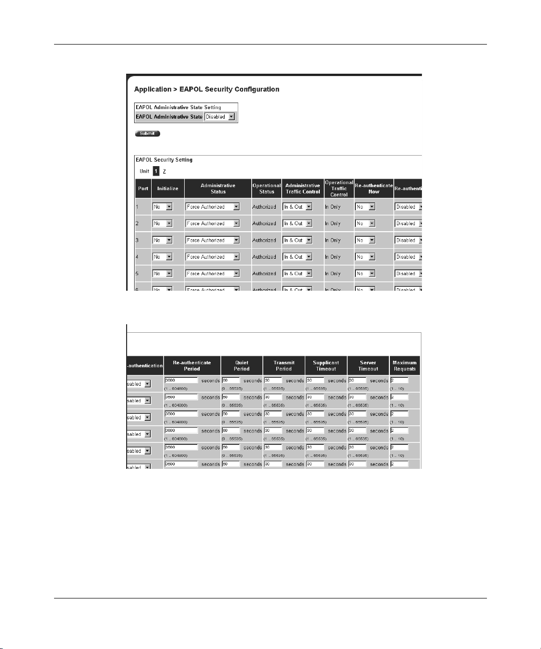
92 Configuring the switch
Figure 30 EAPOL Security Configuration page (1 of 2)
Figure 31 EAPOL Security Configuration page (2 of 2)
209570-C
Page 93

Table 2 7 describes the fields on the EAPOL Security Configuration page.
Table 2 7 EAPOL Security Configuration page fields
Section Item Range Description
Configuring the switch 93
EAPOL
Administrative
State Setting
EAPOL Security
Setting
EAPOL Administrative
State
Unit Displays the unit you are viewing.
Port 1 to 28 Displays the port number.
Initialize (1) Yes
Administrative Status (1) Force
Operational Status (1) Authorized
Administrative Traffic
Control
Operational Traffic
Control
Re-authenticate Now (1) Yes
Re-authentication (1) Enabled
Re-authentication Period 1..604800 With Re-authentication enabled, allows you to
Quiet Period 0..65535 Allows you to specify the time interval between an
Transmit Period 1..65535 Allows you to specify how long the switch waits for
Supplicant Timeout 1..65535 Allows you to specify how long the switch waits for
Server Timeout 1..65535 Allows you to specify how long the switch waits for
Maximum Requests 1..10 Allows you to specify the number of times the
(1) Enabled
(2) Disabled
(2) No
Unauthorized
(2) Auto
(3) Force
Authorized
(2) Unauthorized
(1) In & Out
(2) In Only
(1) In & Out
(2) In Only
(2) No
(2) Disabled
Enables or disables EAPOL-based security.
Activates EAPOL state on this port.
Allows you to set the EAPOL authorization status:
• Force Unauthorized—Always unauthorized
• Auto—Status depends on EAP authentication
results
• Force Authorized—Always authorized
Displays the current authorization status.
Allows you to set EAPOL authentication either for
incoming and outgoing traffic or for incoming traffic
only.
Displays the current administrative traffic control
setting.
Allows you to activate EAPOL authentication
immediately, without waiting for the
re-authentication period to expire.
Allows you to repeat EAPOL authentication
according to the time value specified in
Re-authentication Period field.
specify the time period between successive
EAPOL authentications.
authentication failure and the start of a new
authentication attempt.
the supplicant to respond to EAP Request/Identity
packets.
the supplicant to respond to all EAP packets,
except EAP Request/Identity packets.
the RADIUS server to respond to all EAP packets.
switch attempts to resend EAP packets to a
supplicant.
Using Web-based Management for the Business Policy Switch 2000 Software Version 2.0
Page 94

94 Configuring the switch
2 Complete fields as described in the table.
3 Click Submit.
Managing remote access by IP address
Beginning with software version 1.2, you can configure the remote access you
allow. You can specify up to 10 IP addresses to allow Web access, SNMP access,
or Telnet access to the BPS 2000.
To configure remote access using the Web-based management system:
1 From the main menu of the Business Policy Switch 2000 Web-based
Manager, choose Configuration > Remote Access.
The Remote Access page opens (Figure 32).
209570-C
Page 95

Configuring the switch 95
Figure 32 Remote Access page
Table 2 8 describes the fields on the Remote Access page.
Table 2 8 Remote Access page fields
Section Item Range Description
Remote Access
Settings
Using Web-based Management for the Business Policy Switch 2000 Software Version 2.0
Telnet/Access (1)Allowed
(2) Disallowed
Telnet/Use List (1) Yes
(2) No
SNMP/Access (1)Allowed
(2) Disallowed
SNMP/Use List (1) Yes
(2) No
Web Page/Access Displays allowed Web access.
Allows Telnet access.
Restricts Telnet access to the specified 10 source
IP addresses.
Allows SNMP access.
Restricts SNMP access to the specified 10 source
IP addresses.
Page 96

96 Configuring the switch
Table 2 8 Remote Access page fields (continued)
Section Item Range Description
Allowed Source IP
and Subnet Mask
Web/Use List (1) Yes
(2) No
Allowed Source IP XXX.XXX.XXX.
Allowed Source Mask XXX.XXX.XXX.
XXX
XXX
Restricts Web access to the specified 10 source IP
addresses.
Enter the source IP address you want to allow
switch access.
Enter the source IP mask you want to allow switch
access.
2 Complete fields as described in the table.
3 Click Submit.
Configuring MAC address-based security
Beginning with software version 1.1, the MAC address-based security system
allows you to specify a range of system responses to unauthorized network access
to your switch with the Web-based management system.
209570-C
The system response can range from sending a trap to disabling the port. The
network access control is based on the MAC source addresses (SAs) of the
authorized stations. You can specify a list of up to 448 MAC SAs that are
authorized to access the switch. You can also specify the ports that each MAC SA
is allowed to access. The options for allowed MAC SA port access include:
NONE, ALL, and single or multiple ports that are specified in a list, for example,
1-4, 6, 9, and so forth. You must also include the MAC SA of any router
connected to any secure ports.
When the switch software detects an SA security violation, the response can be to
send a trap, turn on destination address (DA) filtering for all SAs, disable the
specific port, or any combination of these three options.
Page 97

Configuring the switch 97
Beginning with software version 2.0, you can configure the BPS 2000 to drop all
packets having a specified MAC destination address (DA). You can create a list of
up to 10 MAC DAs you want to filter.The packet with the specified MAC DA will
be dropped regardless of the ingress port, source address (SA) intrusion, or VLAN
membership.
Note: Ensure that you do not enter the MAC address of the switch or
stack you are working on.
This feature is available only with BPS2000 software version 2.0 and higher.
Also, this feature is unavailable on the BayStack 450 or 410 switches. In a
Hybrid stack, only the BPS 2000 will filter the specified MAC DAs.
Note: After configuring the switch for MAC address-based security,
you must enable the ports you want, using the Port Configuration page.
Configuring MAC address-based security
To configure MAC address-based security using the Web-based management
system:
1 From the main menu, choose Application > MAC Address Security >
Security Configuration.
The Security Configuration page opens (Figure 33).
Using Web-based Management for the Business Policy Switch 2000 Software Version 2.0
Page 98

98 Configuring the switch
Figure 33 Security Configuration page
Table 2 9 describes the items on the Security Configuration page.
Table 2 9 Security Configuration page items
Section Item Range Description
MAC Address
Security Setting
MAC Address
Security
MAC Address
Security
SNMP-Locked
Partition Port on
Intrusion
Detected
(1) Enabled
(2) Disabled
(1) Enabled
(2) Disabled
(1) Forever
(2) Enabled
(3) Disabled
Enables the MAC address security features.
Enables locking SNMP, so that you cannot use SNMP to
modify the MAC address security features.
Configures how the switch reacts to an intrusion event:
• Forever—The port is disabled and remains disabled
(partitioned) until reset. The port does not reset after
the Partition Time elapses.
• Enabled—The port is disabled, then automatically
reset to enabled after the time specified in the
Partition Time field elapses.
• Disabled—The port remains enabled, even if an
intrusion event is detected.
209570-C
Page 99

Table 2 9 Security Configuration page items (continued)
Section Item Range Description
Partition Time 1 to 65535 Sets the time to partition a port on intrusion.
Note: Use this field only if the Partition Port on Intrusion
Detected field is set to Enabled.
MAC Security Table/
Clear by Ports
MAC Security Table/
Learn by Ports
DA Filtering on
Intrusion
Detected
Generate SNMP
Trap on Intrusion
Action Allows you to clear specific ports from participation in the
Port List Will be blank.
Current Learning
Mode
Action Allows you to identify ports that will learn incoming MAC
Port List Displays all the ports that will learn incoming MAC
Current Learning
Mode
(1) Enabled
(2) Disabled
(1) Enabled
(2) Disabled
(1) Enabled
(2) Disabled
Enables you to isolate the intruding node (discard) the
packets.
Enables generation of an SNMP when an intrusion is
detected.
MAC address security features.
Will be blank.
addresses. All source MAC addresses of any packets
received on a specified port(s) are added to the MAC
Security Table (maximum of 448 MAC addresses
allowed).
address to detect intrusions (unallowed MAC
addresses).
Enables learning.
Configuring the switch 99
2 On the Security Configuration page, type information in the text boxes, or
select from a list.
3 Click Submit.
Configuring ports
In this section, you create a list of ports, and you can add ports to or delete ports
from each list.
To activate an entry or add or delete ports to a list:
1 From the main menu, choose Application > MAC Address Security > Port
Lists.
The Port Lists page opens (Figure 34).
Using Web-based Management for the Business Policy Switch 2000 Software Version 2.0
Page 100

100 Configuring the switch
Figure 34 Port Lists page
Table 3 0 describes the items on the Ports Lists page.
Table 3 0 Ports Lists page items
Item Range Description
Entry These are the lists of ports.
Action Allows you to add or delete ports to the lists.
Port List
Displays which ports are associated with each list.
2 To add or delete ports to a list, click the icon in the Action column in the list
row you want.
The Port List View, Port List page opens (Figure 35).
209570-C
 Loading...