

Page 1

Part No. P0609330 3.0
October 29, 2004
Business Communications
Manager
Management Guide
Page 2

2
Copyright © 2004 Nortel Networks
All rights reserved. May, 2004.
The information in this document is subject to change without notice. The statements, configurations, technical data, and
recommendations in this document are believed to be accurate and reliable, but are presented without express or implied
warranty. Users must take full responsibility for their applications of any products specified in this document. The
information in this document is proprietary to Nortel Networks NA Inc.
Trademarks
NORTEL NETWORKS and Business Communications Manager, are trademarks of Nortel Networks NA Inc.
Microsoft, MS, MS-DOS, Windows, and Windows NT are registered trademarks of Microsoft Corporation.
Symbol, Spectrum24, and NetVision are registered trademarks of Symbol Technologies, Inc.
All other trademarks and registered trademarks are the property of their respective owners.
Software licensing
The Apache Group
Copyright (c) 1995-1999 The Apache Group. All rights reserved.
Redistribution and use in source and binary forms, with or without modification, are permitted
provided that these conditions are met:
1 Redistributions of source code must retain the above copyright notice, this list of conditions
and the following disclaimer.
2 Redistributions in binary form must reproduce the above copyright notice, this list of
conditions and the following disclaimer in the documentation and/or other materials provided
with the distribution.
3 All advertising materials mentioning features or use of this software must display the
following acknowledgment:
4 “This product includes software developed by the Apache Group for use in the Apache HTTP
server project (http://www.apache.org/).”
5 The names “Apache Server” and “Apache Group” must not be used to endorse or promote
products derived from this software without prior written permission.
6 For written permission, please contact apache@apache.org.
7 Products derived from this software may not be called “Apache” nor may “Apache” appear in
their names without prior written permission of the Apache Group.
8 Redistributions of any form whatsoever must retain the following acknowledgment:
9 “This product includes software developed by the Apache Group for use in the Apache HTTP
server project (http://www.apache.org/).”
THIS SOFTWARE IS PROVIDED BY THE APACHE GROUP “AS IS” AND ANY
EXPRESSED OR IMPLIED WARRANTIES, INCLUDING, BUT NOT LIMITED TO, THE
IMPLIED WARRANTIES OF MERCHANTABILITY AND FITNESS FOR A PARTICULAR
PURPOSE ARE DISCLAIMED. IN NO EVENT SHALL THE APACHE GROUP OR ITS
P0609330 3.0
Page 3

CONTRIBUTORS BE LIABLE FOR ANY DIRECT, INDIRECT, INCIDENTAL, SPECIAL,
EXEMPLARY, OR CONSEQUENTIAL DAMAGES (INCLUDING, BUT NOT LIMITED TO,
PROCUREMENT OF SUBSTITUTE GOODS OR SERVICES; LOSS OF USE, DATA, OR
PROFITS; OR BUSINESS INTERRUPTION) HOWEVER CAUSED AND ON ANY THEORY
OF LIABILITY, WHETHER IN CONTRACT, STRICT LIABILITY, OR TORT (INCLUDING
NEGLIGENCE OR OTHERWISE) ARISING IN ANY WAY OUT OF THE USE OF THIS
SOFTWARE, EVEN IF ADVISED OF THE POSSIBILITY OF SUCH DAMAGE.
This software consists of voluntary contributions made by many individuals on behalf of the
Apache Group and was originally based on public domain software written at the National Center
for Supercomputing Applications, University of Illinois, Urbana-Champaign. For more
information on the Apache Group and the Apache HTTP server project, please see
http://www.apache.org/.
3
Business Communications Manager Management Guide
Page 4

4
P0609330 3.0
Page 5

Contents
Preface . . . . . . . . . . . . . . . . . . . . . . . . . . . . . . . . . . . . . . . . . . . . . . . . . . . . . . 17
Purpose . . . . . . . . . . . . . . . . . . . . . . . . . . . . . . . . . . . . . . . . . . . . . . . . . . . . . . . . . . . . 17
Audience . . . . . . . . . . . . . . . . . . . . . . . . . . . . . . . . . . . . . . . . . . . . . . . . . . . . . . . . . . . 17
Organization . . . . . . . . . . . . . . . . . . . . . . . . . . . . . . . . . . . . . . . . . . . . . . . . . . . . . . . . 17
Symbols used in this guide . . . . . . . . . . . . . . . . . . . . . . . . . . . . . . . . . . . . . . . . . . . . . 18
Display Tips . . . . . . . . . . . . . . . . . . . . . . . . . . . . . . . . . . . . . . . . . . . . . . . . . . . . . . . . . 19
Text conventions . . . . . . . . . . . . . . . . . . . . . . . . . . . . . . . . . . . . . . . . . . . . . . . . . . . . . 20
Acronyms used in this guide . . . . . . . . . . . . . . . . . . . . . . . . . . . . . . . . . . . . . . . . . . . . 21
How to get help . . . . . . . . . . . . . . . . . . . . . . . . . . . . . . . . . . . . . . . . . . . . . . . . . . . . . . 23
Related publications . . . . . . . . . . . . . . . . . . . . . . . . . . . . . . . . . . . . . . . . . . . . . . . . . . 24
Chapter 1
Management Overview . . . . . . . . . . . . . . . . . . . . . . . . . . . . . . . . . . . . . . . . . 27
Network Administration Objectives . . . . . . . . . . . . . . . . . . . . . . . . . . . . . . . . . . . . . . . 27
Network management model . . . . . . . . . . . . . . . . . . . . . . . . . . . . . . . . . . . . . . . . 28
Network Topology and Management Interfaces . . . . . . . . . . . . . . . . . . . . . . . . . . . . . 29
Network management physical interfaces . . . . . . . . . . . . . . . . . . . . . . . . . . . . . . 30
SNMP Network Management Concepts . . . . . . . . . . . . . . . . . . . . . . . . . . . . . . . . . . . 32
Network management communication protocols . . . . . . . . . . . . . . . . . . . . . . . . . 32
SNMP network structure . . . . . . . . . . . . . . . . . . . . . . . . . . . . . . . . . . . . . . . . . . . . 32
Network Management and Maintenance Applications . . . . . . . . . . . . . . . . . . . . . . . . 33
Unified Manager . . . . . . . . . . . . . . . . . . . . . . . . . . . . . . . . . . . . . . . . . . . . . . . . . . . . . 34
Using the Unified Manager main page buttons . . . . . . . . . . . . . . . . . . . . . . . . . . . 35
Using Unified Manager . . . . . . . . . . . . . . . . . . . . . . . . . . . . . . . . . . . . . . . . . . . . . . . . 40
Understanding the navigation tree headings . . . . . . . . . . . . . . . . . . . . . . . . . . . . . 40
Logging off Unified Manager . . . . . . . . . . . . . . . . . . . . . . . . . . . . . . . . . . . . . . . . . 42
Unified Manager Maintenance Page Overview . . . . . . . . . . . . . . . . . . . . . . . . . . . . . . 43
Maintenance page access . . . . . . . . . . . . . . . . . . . . . . . . . . . . . . . . . . . . . . . . . . 44
Support . . . . . . . . . . . . . . . . . . . . . . . . . . . . . . . . . . . . . . . . . . . . . . . . . . . . . . . . . 45
Maintenance . . . . . . . . . . . . . . . . . . . . . . . . . . . . . . . . . . . . . . . . . . . . . . . . . . . . . 46
1
Configure . . . . . . . . . . . . . . . . . . . . . . . . . . . . . . . . . . . . . . . . . . . . . . . . . . . . 36
Wizards . . . . . . . . . . . . . . . . . . . . . . . . . . . . . . . . . . . . . . . . . . . . . . . . . . . . . . 36
Navigating the wizards . . . . . . . . . . . . . . . . . . . . . . . . . . . . . . . . . . . . . . . . . . 38
Installing clients . . . . . . . . . . . . . . . . . . . . . . . . . . . . . . . . . . . . . . . . . . . . . . . 38
CallPilot . . . . . . . . . . . . . . . . . . . . . . . . . . . . . . . . . . . . . . . . . . . . . . . . . . . . . 39
Documentation . . . . . . . . . . . . . . . . . . . . . . . . . . . . . . . . . . . . . . . . . . . . . . . . 40
BRU . . . . . . . . . . . . . . . . . . . . . . . . . . . . . . . . . . . . . . . . . . . . . . . . . . . . . . . . 40
Maintenance . . . . . . . . . . . . . . . . . . . . . . . . . . . . . . . . . . . . . . . . . . . . . . . . . . 40
Contact . . . . . . . . . . . . . . . . . . . . . . . . . . . . . . . . . . . . . . . . . . . . . . . . . . . . . . 45
Alarms and traps . . . . . . . . . . . . . . . . . . . . . . . . . . . . . . . . . . . . . . . . . . . . . . 45
Business Communications Manager Management Guide
Page 6

2 Contents
Management Guide Overview . . . . . . . . . . . . . . . . . . . . . . . . . . . . . . . . . . . . . . . . . . . 51
Chapter 2
Fault Management System . . . . . . . . . . . . . . . . . . . . . . . . . . . . . . . . . . . . . . 59
BCM Fault Management Tools . . . . . . . . . . . . . . . . . . . . . . . . . . . . . . . . . . . . . . . . . . 59
Alarm Management System . . . . . . . . . . . . . . . . . . . . . . . . . . . . . . . . . . . . . . . . . . . . 60
Alarm Reporting System . . . . . . . . . . . . . . . . . . . . . . . . . . . . . . . . . . . . . . . . . . . . . . . 61
Accessing and configuring the Alarm System . . . . . . . . . . . . . . . . . . . . . . . . . . . . . . . 66
SNMP Traps . . . . . . . . . . . . . . . . . . . . . . . . . . . . . . . . . . . . . . . . . . . . . . . . . . . . . . . . 75
Configuring an SNMP Community . . . . . . . . . . . . . . . . . . . . . . . . . . . . . . . . . . . . . . . . 77
System information . . . . . . . . . . . . . . . . . . . . . . . . . . . . . . . . . . . . . . . . . . . . . 46
Order and enable optional components . . . . . . . . . . . . . . . . . . . . . . . . . . . . . 47
Install optional components . . . . . . . . . . . . . . . . . . . . . . . . . . . . . . . . . . . . . . 48
Maintenance tools . . . . . . . . . . . . . . . . . . . . . . . . . . . . . . . . . . . . . . . . . . . . . 49
Fault management overview . . . . . . . . . . . . . . . . . . . . . . . . . . . . . . . . . . . . . . . . . 51
Service management overview . . . . . . . . . . . . . . . . . . . . . . . . . . . . . . . . . . . . . . . 51
Log management overview . . . . . . . . . . . . . . . . . . . . . . . . . . . . . . . . . . . . . . . . . . 52
BCM Monitor overview . . . . . . . . . . . . . . . . . . . . . . . . . . . . . . . . . . . . . . . . . . . . . 52
Performance management overview . . . . . . . . . . . . . . . . . . . . . . . . . . . . . . . . . . 53
Security management overview . . . . . . . . . . . . . . . . . . . . . . . . . . . . . . . . . . . . . . 53
Backup and restore overview . . . . . . . . . . . . . . . . . . . . . . . . . . . . . . . . . . . . . . . . 54
Troubleshooting and diagnostics activities overview . . . . . . . . . . . . . . . . . . . . . . 55
Event sources . . . . . . . . . . . . . . . . . . . . . . . . . . . . . . . . . . . . . . . . . . . . . . . . . . . . 62
MSC events . . . . . . . . . . . . . . . . . . . . . . . . . . . . . . . . . . . . . . . . . . . . . . . . . . . . . . 62
MSC event and alarm conditions . . . . . . . . . . . . . . . . . . . . . . . . . . . . . . . . . . 62
MSC (core telephony) logs . . . . . . . . . . . . . . . . . . . . . . . . . . . . . . . . . . . . . . . . . . 63
NT Event log database . . . . . . . . . . . . . . . . . . . . . . . . . . . . . . . . . . . . . . . . . . . . . 64
Alarm manager . . . . . . . . . . . . . . . . . . . . . . . . . . . . . . . . . . . . . . . . . . . . . . . . . . . 64
Alarm database . . . . . . . . . . . . . . . . . . . . . . . . . . . . . . . . . . . . . . . . . . . . . . . . . . . 64
Alarm banner and alarm browser . . . . . . . . . . . . . . . . . . . . . . . . . . . . . . . . . . . . . 64
Alarm system interfaces . . . . . . . . . . . . . . . . . . . . . . . . . . . . . . . . . . . . . . . . . 64
BCM alarm severity . . . . . . . . . . . . . . . . . . . . . . . . . . . . . . . . . . . . . . . . . . . . . . . . 65
Enabling the alarm service . . . . . . . . . . . . . . . . . . . . . . . . . . . . . . . . . . . . . . . . . . 67
Accessing the Alarm Banner to monitor alarm notification . . . . . . . . . . . . . . . . . . 68
Accessing the Alarm Browser to analyze alarm detail . . . . . . . . . . . . . . . . . . . . . 69
Configuring Alarm Manager settings . . . . . . . . . . . . . . . . . . . . . . . . . . . . . . . . . . . 70
BCM alarm and SNMP trap list . . . . . . . . . . . . . . . . . . . . . . . . . . . . . . . . . . . . . . . 75
Alarm banner, NT event database, and SNMP trap correlation . . . . . . . . . . . . . . 76
SNMP trap filtering . . . . . . . . . . . . . . . . . . . . . . . . . . . . . . . . . . . . . . . . . . . . . . . . 76
SNMP guidelines . . . . . . . . . . . . . . . . . . . . . . . . . . . . . . . . . . . . . . . . . . . . . . . . . . 77
About defining SNMP trap destinations . . . . . . . . . . . . . . . . . . . . . . . . . . . . . . . . 77
Configuring SNMP summary attributes . . . . . . . . . . . . . . . . . . . . . . . . . . . . . . . . . 78
P0609330 3.0
Page 7

Contents 3
Adding a community to an SNMP community list . . . . . . . . . . . . . . . . . . . . . . . . . 79
Modifying an SNMP community list . . . . . . . . . . . . . . . . . . . . . . . . . . . . . . . . . . . . 81
Deleting an SNMP community . . . . . . . . . . . . . . . . . . . . . . . . . . . . . . . . . . . . . . . 81
Configuring an SNMP Manager List . . . . . . . . . . . . . . . . . . . . . . . . . . . . . . . . . . . . . . 81
Adding a manager to the SNMP manager list . . . . . . . . . . . . . . . . . . . . . . . . . . . . 81
Modifying an SNMP manager . . . . . . . . . . . . . . . . . . . . . . . . . . . . . . . . . . . . . . . . 84
Deleting an SNMP manager . . . . . . . . . . . . . . . . . . . . . . . . . . . . . . . . . . . . . . . . . 84
Configuring an SNMP Trap Community List . . . . . . . . . . . . . . . . . . . . . . . . . . . . . . . . 85
Adding a trap community to the SNMP community list . . . . . . . . . . . . . . . . . . . . . 85
Modifying an SNMP trap community . . . . . . . . . . . . . . . . . . . . . . . . . . . . . . . . . . . 87
Deleting an SNMP trap community . . . . . . . . . . . . . . . . . . . . . . . . . . . . . . . . . . . . 87
Alarm Analysis and Clearing Procedures . . . . . . . . . . . . . . . . . . . . . . . . . . . . . . . . . . 89
SNMP Event Messages . . . . . . . . . . . . . . . . . . . . . . . . . . . . . . . . . . . . . . . . . . . . 90
Using the component ID and event ID summary tables . . . . . . . . . . . . . . . . . . . . 90
Component ID (alarm) summary information . . . . . . . . . . . . . . . . . . . . . . . . . . . . . . . 92
Component event ID . . . . . . . . . . . . . . . . . . . . . . . . . . . . . . . . . . . . . . . . . . . . . . . 95
Component ID/SNMP Trap Error interpretation . . . . . . . . . . . . . . . . . . . . . . . . . . . . . 100
Component ID alarm descriptions . . . . . . . . . . . . . . . . . . . . . . . . . . . . . . . . . . . . . . . 101
Atapi . . . . . . . . . . . . . . . . . . . . . . . . . . . . . . . . . . . . . . . . . . . . . . . . . . . . . . . . . . 102
Autochk . . . . . . . . . . . . . . . . . . . . . . . . . . . . . . . . . . . . . . . . . . . . . . . . . . . . . . . . 102
BCMAm p . . . . . . . . . . . . . . . . . . . . . . . . . . . . . . . . . . . . . . . . . . . . . . . . . . . . . . . 102
Browser . . . . . . . . . . . . . . . . . . . . . . . . . . . . . . . . . . . . . . . . . . . . . . . . . . . . . . . . 105
BRU . . . . . . . . . . . . . . . . . . . . . . . . . . . . . . . . . . . . . . . . . . . . . . . . . . . . . . . . . . . 105
CDRTransfer . . . . . . . . . . . . . . . . . . . . . . . . . . . . . . . . . . . . . . . . . . . . . . . . . . . . 108
cfsServr . . . . . . . . . . . . . . . . . . . . . . . . . . . . . . . . . . . . . . . . . . . . . . . . . . . . . . . . 111
CTE . . . . . . . . . . . . . . . . . . . . . . . . . . . . . . . . . . . . . . . . . . . . . . . . . . . . . . . . . . . 114
DCOM . . . . . . . . . . . . . . . . . . . . . . . . . . . . . . . . . . . . . . . . . . . . . . . . . . . . . . . . . 114
DECTAlarms . . . . . . . . . . . . . . . . . . . . . . . . . . . . . . . . . . . . . . . . . . . . . . . . . . . . 116
DECTMtce . . . . . . . . . . . . . . . . . . . . . . . . . . . . . . . . . . . . . . . . . . . . . . . . . . . . . . 116
DhcpServer . . . . . . . . . . . . . . . . . . . . . . . . . . . . . . . . . . . . . . . . . . . . . . . . . . . . . 116
disk . . . . . . . . . . . . . . . . . . . . . . . . . . . . . . . . . . . . . . . . . . . . . . . . . . . . . . . . . . . 116
DNS . . . . . . . . . . . . . . . . . . . . . . . . . . . . . . . . . . . . . . . . . . . . . . . . . . . . . . . . . . . 117
DrWatson . . . . . . . . . . . . . . . . . . . . . . . . . . . . . . . . . . . . . . . . . . . . . . . . . . . . . . 119
emsManager . . . . . . . . . . . . . . . . . . . . . . . . . . . . . . . . . . . . . . . . . . . . . . . . . . . . 119
eventLog . . . . . . . . . . . . . . . . . . . . . . . . . . . . . . . . . . . . . . . . . . . . . . . . . . . . . . . 121
FTMSS . . . . . . . . . . . . . . . . . . . . . . . . . . . . . . . . . . . . . . . . . . . . . . . . . . . . . . . . 121
HotDesking . . . . . . . . . . . . . . . . . . . . . . . . . . . . . . . . . . . . . . . . . . . . . . . . . . . . . 124
Inventory Service . . . . . . . . . . . . . . . . . . . . . . . . . . . . . . . . . . . . . . . . . . . . . . . . 126
IPRIP2 . . . . . . . . . . . . . . . . . . . . . . . . . . . . . . . . . . . . . . . . . . . . . . . . . . . . . . . . . 126
IPSecIKE . . . . . . . . . . . . . . . . . . . . . . . . . . . . . . . . . . . . . . . . . . . . . . . . . . . . . . . 128
IPXRouterManager . . . . . . . . . . . . . . . . . . . . . . . . . . . . . . . . . . . . . . . . . . . . . . . 134
IVR . . . . . . . . . . . . . . . . . . . . . . . . . . . . . . . . . . . . . . . . . . . . . . . . . . . . . . . . . . . 134
Business Communications Manager Management Guide
Page 8

4 Contents
JET . . . . . . . . . . . . . . . . . . . . . . . . . . . . . . . . . . . . . . . . . . . . . . . . . . . . . . . . . . . 136
kbdclass . . . . . . . . . . . . . . . . . . . . . . . . . . . . . . . . . . . . . . . . . . . . . . . . . . . . . . . 136
LLNail . . . . . . . . . . . . . . . . . . . . . . . . . . . . . . . . . . . . . . . . . . . . . . . . . . . . . . . . . 138
MGS . . . . . . . . . . . . . . . . . . . . . . . . . . . . . . . . . . . . . . . . . . . . . . . . . . . . . . . . . . 138
Modem . . . . . . . . . . . . . . . . . . . . . . . . . . . . . . . . . . . . . . . . . . . . . . . . . . . . . . . . 143
MPS . . . . . . . . . . . . . . . . . . . . . . . . . . . . . . . . . . . . . . . . . . . . . . . . . . . . . . . . . . 143
MSPAlarmService . . . . . . . . . . . . . . . . . . . . . . . . . . . . . . . . . . . . . . . . . . . . . . . . 146
mspQoS . . . . . . . . . . . . . . . . . . . . . . . . . . . . . . . . . . . . . . . . . . . . . . . . . . . . . . . 146
mspQoSMP . . . . . . . . . . . . . . . . . . . . . . . . . . . . . . . . . . . . . . . . . . . . . . . . . . . . . 146
NCM . . . . . . . . . . . . . . . . . . . . . . . . . . . . . . . . . . . . . . . . . . . . . . . . . . . . . . . . . . 153
NetBT . . . . . . . . . . . . . . . . . . . . . . . . . . . . . . . . . . . . . . . . . . . . . . . . . . . . . . . . . 153
NetIQccm . . . . . . . . . . . . . . . . . . . . . . . . . . . . . . . . . . . . . . . . . . . . . . . . . . . . . . 154
NetIQmc . . . . . . . . . . . . . . . . . . . . . . . . . . . . . . . . . . . . . . . . . . . . . . . . . . . . . . . 156
NetIQObjMgr . . . . . . . . . . . . . . . . . . . . . . . . . . . . . . . . . . . . . . . . . . . . . . . . . . . . 156
NetLinkManager . . . . . . . . . . . . . . . . . . . . . . . . . . . . . . . . . . . . . . . . . . . . . . . . . 157
NetLogon . . . . . . . . . . . . . . . . . . . . . . . . . . . . . . . . . . . . . . . . . . . . . . . . . . . . . . . 157
NGRPCI . . . . . . . . . . . . . . . . . . . . . . . . . . . . . . . . . . . . . . . . . . . . . . . . . . . . . . . 157
Nnu . . . . . . . . . . . . . . . . . . . . . . . . . . . . . . . . . . . . . . . . . . . . . . . . . . . . . . . . . . . 159
NSACD . . . . . . . . . . . . . . . . . . . . . . . . . . . . . . . . . . . . . . . . . . . . . . . . . . . . . . . . 159
NwRdr . . . . . . . . . . . . . . . . . . . . . . . . . . . . . . . . . . . . . . . . . . . . . . . . . . . . . . . . . 159
OSPFMib . . . . . . . . . . . . . . . . . . . . . . . . . . . . . . . . . . . . . . . . . . . . . . . . . . . . . . . 160
Perfctrs . . . . . . . . . . . . . . . . . . . . . . . . . . . . . . . . . . . . . . . . . . . . . . . . . . . . . . . . 160
Perflib . . . . . . . . . . . . . . . . . . . . . . . . . . . . . . . . . . . . . . . . . . . . . . . . . . . . . . . . . 160
Policy Services . . . . . . . . . . . . . . . . . . . . . . . . . . . . . . . . . . . . . . . . . . . . . . . . . . 162
qos_flt_init . . . . . . . . . . . . . . . . . . . . . . . . . . . . . . . . . . . . . . . . . . . . . . . . . . . . . . 162
Rdr . . . . . . . . . . . . . . . . . . . . . . . . . . . . . . . . . . . . . . . . . . . . . . . . . . . . . . . . . . . 162
Router . . . . . . . . . . . . . . . . . . . . . . . . . . . . . . . . . . . . . . . . . . . . . . . . . . . . . . . . . 163
SAM . . . . . . . . . . . . . . . . . . . . . . . . . . . . . . . . . . . . . . . . . . . . . . . . . . . . . . . . . . 166
Save Dump . . . . . . . . . . . . . . . . . . . . . . . . . . . . . . . . . . . . . . . . . . . . . . . . . . . . . 166
Security . . . . . . . . . . . . . . . . . . . . . . . . . . . . . . . . . . . . . . . . . . . . . . . . . . . . . 166
Serial . . . . . . . . . . . . . . . . . . . . . . . . . . . . . . . . . . . . . . . . . . . . . . . . . . . . . . . . . . 170
Service Control Manager . . . . . . . . . . . . . . . . . . . . . . . . . . . . . . . . . . . . . . . . . . 170
SNMP . . . . . . . . . . . . . . . . . . . . . . . . . . . . . . . . . . . . . . . . . . . . . . . . . . . . . . . . . 176
SNMP Trap Agent . . . . . . . . . . . . . . . . . . . . . . . . . . . . . . . . . . . . . . . . . . . . . . . . 176
Srv . . . . . . . . . . . . . . . . . . . . . . . . . . . . . . . . . . . . . . . . . . . . . . . . . . . . . . . . . . . . 176
SSH Secure Shell Server . . . . . . . . . . . . . . . . . . . . . . . . . . . . . . . . . . . . . . . . . . 178
Survivable Remote Gateway . . . . . . . . . . . . . . . . . . . . . . . . . . . . . . . . . . . . . . . . 178
System Status Monitor . . . . . . . . . . . . . . . . . . . . . . . . . . . . . . . . . . . . . . . . . . . . 182
Tcpip . . . . . . . . . . . . . . . . . . . . . . . . . . . . . . . . . . . . . . . . . . . . . . . . . . . . . . . . . . 191
TlntSvr . . . . . . . . . . . . . . . . . . . . . . . . . . . . . . . . . . . . . . . . . . . . . . . . . . . . . . . . . 191
ToneSrvr . . . . . . . . . . . . . . . . . . . . . . . . . . . . . . . . . . . . . . . . . . . . . . . . . . . . . . . 191
UPS . . . . . . . . . . . . . . . . . . . . . . . . . . . . . . . . . . . . . . . . . . . . . . . . . . . . . . . . . . . 192
P0609330 3.0
Page 9

Contents 5
UTPS . . . . . . . . . . . . . . . . . . . . . . . . . . . . . . . . . . . . . . . . . . . . . . . . . . . . . . . . . . 207
VBMain . . . . . . . . . . . . . . . . . . . . . . . . . . . . . . . . . . . . . . . . . . . . . . . . . . . . . . . . 210
VNC Service . . . . . . . . . . . . . . . . . . . . . . . . . . . . . . . . . . . . . . . . . . . . . . . . . . . . 210
VNetManage r . . . . . . . . . . . . . . . . . . . . . . . . . . . . . . . . . . . . . . . . . . . . . . . . . . . 210
VNetQosMonitor . . . . . . . . . . . . . . . . . . . . . . . . . . . . . . . . . . . . . . . . . . . . . . . . . 212
VNetVoIPGtwy . . . . . . . . . . . . . . . . . . . . . . . . . . . . . . . . . . . . . . . . . . . . . . . . . . 212
Voice CTE . . . . . . . . . . . . . . . . . . . . . . . . . . . . . . . . . . . . . . . . . . . . . . . . . . . . . . 215
Voice software . . . . . . . . . . . . . . . . . . . . . . . . . . . . . . . . . . . . . . . . . . . . . . . . . . . 219
VoiceCTI . . . . . . . . . . . . . . . . . . . . . . . . . . . . . . . . . . . . . . . . . . . . . . . . . . . . . . . 237
VoiceManagementSubsystem . . . . . . . . . . . . . . . . . . . . . . . . . . . . . . . . . . . . . . 239
VoiceMSCService . . . . . . . . . . . . . . . . . . . . . . . . . . . . . . . . . . . . . . . . . . . . . . . . 239
VoIPSipGateway . . . . . . . . . . . . . . . . . . . . . . . . . . . . . . . . . . . . . . . . . . . . . . . . . 241
VoiceRecord . . . . . . . . . . . . . . . . . . . . . . . . . . . . . . . . . . . . . . . . . . . . . . . . . . . . 243
VoiceTimeSynch . . . . . . . . . . . . . . . . . . . . . . . . . . . . . . . . . . . . . . . . . . . . . . . . . 243
VoiceWatchdog . . . . . . . . . . . . . . . . . . . . . . . . . . . . . . . . . . . . . . . . . . . . . . . . . . 245
Wins . . . . . . . . . . . . . . . . . . . . . . . . . . . . . . . . . . . . . . . . . . . . . . . . . . . . . . . . . . 248
WINSCTRS . . . . . . . . . . . . . . . . . . . . . . . . . . . . . . . . . . . . . . . . . . . . . . . . . . . . . 248
Workstation . . . . . . . . . . . . . . . . . . . . . . . . . . . . . . . . . . . . . . . . . . . . . . . . . . . . . 248
Events that cause a system restart . . . . . . . . . . . . . . . . . . . . . . . . . . . . . . . . . . . . . . 250
Chapter 3
Service Management System . . . . . . . . . . . . . . . . . . . . . . . . . . . . . . . . . . . 251
Service Manager . . . . . . . . . . . . . . . . . . . . . . . . . . . . . . . . . . . . . . . . . . . . . . . . . . . . 251
Accessing Service Manager . . . . . . . . . . . . . . . . . . . . . . . . . . . . . . . . . . . . . . . . 251
Accessing services and driver status reports . . . . . . . . . . . . . . . . . . . . . . . . . . . 255
Service Definitions . . . . . . . . . . . . . . . . . . . . . . . . . . . . . . . . . . . . . . . . . . . . . . . . . . . 257
Service definition properties . . . . . . . . . . . . . . . . . . . . . . . . . . . . . . . . . . . . . . . . 258
System-level service definitions . . . . . . . . . . . . . . . . . . . . . . . . . . . . . . . . . . . . . . . . 258
Alerter . . . . . . . . . . . . . . . . . . . . . . . . . . . . . . . . . . . . . . . . . . . . . . . . . . . . . . . . . 260
ClipBook server . . . . . . . . . . . . . . . . . . . . . . . . . . . . . . . . . . . . . . . . . . . . . . . . . . 261
COM + Event System . . . . . . . . . . . . . . . . . . . . . . . . . . . . . . . . . . . . . . . . . . . . . 261
Computer Browser . . . . . . . . . . . . . . . . . . . . . . . . . . . . . . . . . . . . . . . . . . . . . . . 262
EventLog . . . . . . . . . . . . . . . . . . . . . . . . . . . . . . . . . . . . . . . . . . . . . . . . . . . . . . . 262
Firebird Guardian Service . . . . . . . . . . . . . . . . . . . . . . . . . . . . . . . . . . . . . . . . . . 263
Firebird Server . . . . . . . . . . . . . . . . . . . . . . . . . . . . . . . . . . . . . . . . . . . . . . . . . . 263
License logging service . . . . . . . . . . . . . . . . . . . . . . . . . . . . . . . . . . . . . . . . . . . . 264
Messenger . . . . . . . . . . . . . . . . . . . . . . . . . . . . . . . . . . . . . . . . . . . . . . . . . . . . . 264
MSDTC . . . . . . . . . . . . . . . . . . . . . . . . . . . . . . . . . . . . . . . . . . . . . . . . . . . . . . . . 265
MSSQLServer . . . . . . . . . . . . . . . . . . . . . . . . . . . . . . . . . . . . . . . . . . . . . . . . . . . 265
MSSQLServerADHelper . . . . . . . . . . . . . . . . . . . . . . . . . . . . . . . . . . . . . . . . . . . 265
Multi-dialup manager . . . . . . . . . . . . . . . . . . . . . . . . . . . . . . . . . . . . . . . . . . . . . . 266
NetIQ AppManager client communication manager . . . . . . . . . . . . . . . . . . . . . . 266
Business Communications Manager Management Guide
Page 10

6 Contents
Nortel Networks Configurable Services . . . . . . . . . . . . . . . . . . . . . . . . . . . . . . . . . . . 285
NetIQ AppManager client resource manager . . . . . . . . . . . . . . . . . . . . . . . . . . . 267
Network DDE . . . . . . . . . . . . . . . . . . . . . . . . . . . . . . . . . . . . . . . . . . . . . . . . . . . 267
Network DDE DSDM . . . . . . . . . . . . . . . . . . . . . . . . . . . . . . . . . . . . . . . . . . . . . . 267
Net logon . . . . . . . . . . . . . . . . . . . . . . . . . . . . . . . . . . . . . . . . . . . . . . . . . . . . . . . 268
Network monitor agent . . . . . . . . . . . . . . . . . . . . . . . . . . . . . . . . . . . . . . . . . . . . 268
NT LM Security support provider . . . . . . . . . . . . . . . . . . . . . . . . . . . . . . . . . . . . 269
NSACD . . . . . . . . . . . . . . . . . . . . . . . . . . . . . . . . . . . . . . . . . . . . . . . . . . . . . . . . 269
Plug and play . . . . . . . . . . . . . . . . . . . . . . . . . . . . . . . . . . . . . . . . . . . . . . . . . . . 270
Protected storage . . . . . . . . . . . . . . . . . . . . . . . . . . . . . . . . . . . . . . . . . . . . . . . . 270
Qos_flt_init . . . . . . . . . . . . . . . . . . . . . . . . . . . . . . . . . . . . . . . . . . . . . . . . . . . . . 271
RDS self-certifying . . . . . . . . . . . . . . . . . . . . . . . . . . . . . . . . . . . . . . . . . . . . . . . 271
Remote access autodial manager . . . . . . . . . . . . . . . . . . . . . . . . . . . . . . . . . . . . 272
Remote access connection manager . . . . . . . . . . . . . . . . . . . . . . . . . . . . . . . . . 272
Remote access server . . . . . . . . . . . . . . . . . . . . . . . . . . . . . . . . . . . . . . . . . . . . 273
Remote procedure call locator . . . . . . . . . . . . . . . . . . . . . . . . . . . . . . . . . . . . . . 273
Remote procedure call service . . . . . . . . . . . . . . . . . . . . . . . . . . . . . . . . . . . . . . 274
Routing and remote access service . . . . . . . . . . . . . . . . . . . . . . . . . . . . . . . . . . 275
Serial port manager . . . . . . . . . . . . . . . . . . . . . . . . . . . . . . . . . . . . . . . . . . . . . . . 275
Server . . . . . . . . . . . . . . . . . . . . . . . . . . . . . . . . . . . . . . . . . . . . . . . . . . . . . . . . . 276
Services Monitor . . . . . . . . . . . . . . . . . . . . . . . . . . . . . . . . . . . . . . . . . . . . . . . . . 276
Spooler . . . . . . . . . . . . . . . . . . . . . . . . . . . . . . . . . . . . . . . . . . . . . . . . . . . . . . . . 277
SQLServerAgent . . . . . . . . . . . . . . . . . . . . . . . . . . . . . . . . . . . . . . . . . . . . . . . . . 277
SSH Secure Shell 2 . . . . . . . . . . . . . . . . . . . . . . . . . . . . . . . . . . . . . . . . . . . . . . 277
Survivable remote gateway . . . . . . . . . . . . . . . . . . . . . . . . . . . . . . . . . . . . . . . . . 278
System event notification . . . . . . . . . . . . . . . . . . . . . . . . . . . . . . . . . . . . . . . . . . 278
Task scheduler . . . . . . . . . . . . . . . . . . . . . . . . . . . . . . . . . . . . . . . . . . . . . . . . . . 279
TCP/IP NetBIOS helper . . . . . . . . . . . . . . . . . . . . . . . . . . . . . . . . . . . . . . . . . . . 279
Tomcat . . . . . . . . . . . . . . . . . . . . . . . . . . . . . . . . . . . . . . . . . . . . . . . . . . . . . . . . 280
UPS - APC Powerchute plus . . . . . . . . . . . . . . . . . . . . . . . . . . . . . . . . . . . . . . . . 280
UPS Console Toggle . . . . . . . . . . . . . . . . . . . . . . . . . . . . . . . . . . . . . . . . . . . . . . 281
VNC server . . . . . . . . . . . . . . . . . . . . . . . . . . . . . . . . . . . . . . . . . . . . . . . . . . . . . 281
Voice Licensing services . . . . . . . . . . . . . . . . . . . . . . . . . . . . . . . . . . . . . . . . . . . 281
Windows installer . . . . . . . . . . . . . . . . . . . . . . . . . . . . . . . . . . . . . . . . . . . . . . . . 282
Windows internet name service . . . . . . . . . . . . . . . . . . . . . . . . . . . . . . . . . . . . . 283
Windows management . . . . . . . . . . . . . . . . . . . . . . . . . . . . . . . . . . . . . . . . . . . . 283
Workstation . . . . . . . . . . . . . . . . . . . . . . . . . . . . . . . . . . . . . . . . . . . . . . . . . . . . . 284
World wide web publishing service . . . . . . . . . . . . . . . . . . . . . . . . . . . . . . . . . . . 284
Alarm service . . . . . . . . . . . . . . . . . . . . . . . . . . . . . . . . . . . . . . . . . . . . . . . . . . . 286
BCMUpgrade . . . . . . . . . . . . . . . . . . . . . . . . . . . . . . . . . . . . . . . . . . . . . . . . . . . 287
Call Detail Recording . . . . . . . . . . . . . . . . . . . . . . . . . . . . . . . . . . . . . . . . . . . . . 287
Doorphone . . . . . . . . . . . . . . . . . . . . . . . . . . . . . . . . . . . . . . . . . . . . . . . . . . . . . 288
P0609330 3.0
Page 11

Contents 7
DECT Alarm monitor . . . . . . . . . . . . . . . . . . . . . . . . . . . . . . . . . . . . . . . . . . . . . . 288
DECT Maintenance console . . . . . . . . . . . . . . . . . . . . . . . . . . . . . . . . . . . . . . . . 289
DECT OAM . . . . . . . . . . . . . . . . . . . . . . . . . . . . . . . . . . . . . . . . . . . . . . . . . . . . . 290
FTP Publishing service . . . . . . . . . . . . . . . . . . . . . . . . . . . . . . . . . . . . . . . . . . . . 290
HotDesking . . . . . . . . . . . . . . . . . . . . . . . . . . . . . . . . . . . . . . . . . . . . . . . . . . . . . 291
Inventory service . . . . . . . . . . . . . . . . . . . . . . . . . . . . . . . . . . . . . . . . . . . . . . . . . 291
IpMusic (BcmAmp) . . . . . . . . . . . . . . . . . . . . . . . . . . . . . . . . . . . . . . . . . . . . . . . 292
IpMusic (Tone Server) . . . . . . . . . . . . . . . . . . . . . . . . . . . . . . . . . . . . . . . . . . . . . 292
IPSecIKE service . . . . . . . . . . . . . . . . . . . . . . . . . . . . . . . . . . . . . . . . . . . . . . . . 293
Line monitor server . . . . . . . . . . . . . . . . . . . . . . . . . . . . . . . . . . . . . . . . . . . . . . . 293
Media gateway server . . . . . . . . . . . . . . . . . . . . . . . . . . . . . . . . . . . . . . . . . . . . . 294
Media path server . . . . . . . . . . . . . . . . . . . . . . . . . . . . . . . . . . . . . . . . . . . . . . . . 295
Media services manager . . . . . . . . . . . . . . . . . . . . . . . . . . . . . . . . . . . . . . . . . . . 295
Message trace tool . . . . . . . . . . . . . . . . . . . . . . . . . . . . . . . . . . . . . . . . . . . . . . . 296
Microsoft DHCP server . . . . . . . . . . . . . . . . . . . . . . . . . . . . . . . . . . . . . . . . . . . . 297
Microsoft DNS server . . . . . . . . . . . . . . . . . . . . . . . . . . . . . . . . . . . . . . . . . . . . . 297
Net link manager . . . . . . . . . . . . . . . . . . . . . . . . . . . . . . . . . . . . . . . . . . . . . . . . . 298
Nortel Networks IVR . . . . . . . . . . . . . . . . . . . . . . . . . . . . . . . . . . . . . . . . . . . . . . 298
Nortel Networks license service . . . . . . . . . . . . . . . . . . . . . . . . . . . . . . . . . . . . . 299
Policy service . . . . . . . . . . . . . . . . . . . . . . . . . . . . . . . . . . . . . . . . . . . . . . . . . . . 299
PPPoE service . . . . . . . . . . . . . . . . . . . . . . . . . . . . . . . . . . . . . . . . . . . . . . . . . . 300
SNMP . . . . . . . . . . . . . . . . . . . . . . . . . . . . . . . . . . . . . . . . . . . . . . . . . . . . . . . . . 300
SNMP Trap service . . . . . . . . . . . . . . . . . . . . . . . . . . . . . . . . . . . . . . . . . . . . . . . 301
System status monitor . . . . . . . . . . . . . . . . . . . . . . . . . . . . . . . . . . . . . . . . . . . . . 301
Telephony service . . . . . . . . . . . . . . . . . . . . . . . . . . . . . . . . . . . . . . . . . . . . . . . . 301
Tlntsvr . . . . . . . . . . . . . . . . . . . . . . . . . . . . . . . . . . . . . . . . . . . . . . . . . . . . . . . . . 302
UNISTIM Terminal proxy server . . . . . . . . . . . . . . . . . . . . . . . . . . . . . . . . . . . . . 302
VBMain . . . . . . . . . . . . . . . . . . . . . . . . . . . . . . . . . . . . . . . . . . . . . . . . . . . . . . . . 303
Voice CFS . . . . . . . . . . . . . . . . . . . . . . . . . . . . . . . . . . . . . . . . . . . . . . . . . . . . . . 303
Voice CTE . . . . . . . . . . . . . . . . . . . . . . . . . . . . . . . . . . . . . . . . . . . . . . . . . . . . . . 304
VoiceCTI . . . . . . . . . . . . . . . . . . . . . . . . . . . . . . . . . . . . . . . . . . . . . . . . . . . . . . . 304
Voice mail . . . . . . . . . . . . . . . . . . . . . . . . . . . . . . . . . . . . . . . . . . . . . . . . . . . . . . 305
Voice management subsystem . . . . . . . . . . . . . . . . . . . . . . . . . . . . . . . . . . . . . . 306
Voice MSC service . . . . . . . . . . . . . . . . . . . . . . . . . . . . . . . . . . . . . . . . . . . . . . . 306
Voice Net QoS monitor . . . . . . . . . . . . . . . . . . . . . . . . . . . . . . . . . . . . . . . . . . . . 307
Voice NNU diagnostics . . . . . . . . . . . . . . . . . . . . . . . . . . . . . . . . . . . . . . . . . . . . 308
Voice software alarm monitor . . . . . . . . . . . . . . . . . . . . . . . . . . . . . . . . . . . . . . . 309
Voice time synch . . . . . . . . . . . . . . . . . . . . . . . . . . . . . . . . . . . . . . . . . . . . . . . . . 310
Voice WAN . . . . . . . . . . . . . . . . . . . . . . . . . . . . . . . . . . . . . . . . . . . . . . . . . . . . . 310
Voice watchdog . . . . . . . . . . . . . . . . . . . . . . . . . . . . . . . . . . . . . . . . . . . . . . . . . . 311
VoIP Gateway . . . . . . . . . . . . . . . . . . . . . . . . . . . . . . . . . . . . . . . . . . . . . . . . . . . 311
VoIP SIP Gateway . . . . . . . . . . . . . . . . . . . . . . . . . . . . . . . . . . . . . . . . . . . . . . . 312
Business Communications Manager Management Guide
Page 12

8 Contents
Watchdog Service . . . . . . . . . . . . . . . . . . . . . . . . . . . . . . . . . . . . . . . . . . . . . . . . . . . 313
Chapter 4
Log Management . . . . . . . . . . . . . . . . . . . . . . . . . . . . . . . . . . . . . . . . . . . . . 315
Business Communications Manager Logs . . . . . . . . . . . . . . . . . . . . . . . . . . . . . . . . 315
Media service card (core telephony) logs . . . . . . . . . . . . . . . . . . . . . . . . . . . . . . . . . 315
Archlogs . . . . . . . . . . . . . . . . . . . . . . . . . . . . . . . . . . . . . . . . . . . . . . . . . . . . . . . . . . . 320
Using Watchdog with Service Manager . . . . . . . . . . . . . . . . . . . . . . . . . . . . . . . 314
MSC System test log . . . . . . . . . . . . . . . . . . . . . . . . . . . . . . . . . . . . . . . . . . . . . . 316
MSC System administration log . . . . . . . . . . . . . . . . . . . . . . . . . . . . . . . . . . . . . 316
MSC Network event log . . . . . . . . . . . . . . . . . . . . . . . . . . . . . . . . . . . . . . . . . . . 317
Displaying the MSC log information . . . . . . . . . . . . . . . . . . . . . . . . . . . . . . . . . . 317
Erasing the MSC log information . . . . . . . . . . . . . . . . . . . . . . . . . . . . . . . . . . . . 319
Report-a-problem wizard . . . . . . . . . . . . . . . . . . . . . . . . . . . . . . . . . . . . . . . . . . . 320
Archlog scheduler . . . . . . . . . . . . . . . . . . . . . . . . . . . . . . . . . . . . . . . . . . . . . . . . 326
Archlog viewer . . . . . . . . . . . . . . . . . . . . . . . . . . . . . . . . . . . . . . . . . . . . . . . . . . . 328
Archlog settings . . . . . . . . . . . . . . . . . . . . . . . . . . . . . . . . . . . . . . . . . . . . . . . . . . 329
Browse logs folder . . . . . . . . . . . . . . . . . . . . . . . . . . . . . . . . . . . . . . . . . . . . . . . . 331
Obtaining NT Event Logs from Archlog . . . . . . . . . . . . . . . . . . . . . . . . . . . . . . . . 332
Chapter 5
BCM Monitor. . . . . . . . . . . . . . . . . . . . . . . . . . . . . . . . . . . . . . . . . . . . . . . . . 335
Starting BCM Monitor . . . . . . . . . . . . . . . . . . . . . . . . . . . . . . . . . . . . . . . . . . . . . . . . 335
Installing BCM Monitor on your computer . . . . . . . . . . . . . . . . . . . . . . . . . . . . . . 335
Starting BCM Monitor . . . . . . . . . . . . . . . . . . . . . . . . . . . . . . . . . . . . . . . . . . . . . 336
Saving your logon information . . . . . . . . . . . . . . . . . . . . . . . . . . . . . . . . . . . . . . . 336
Using BCM Monitor to analyze your system status . . . . . . . . . . . . . . . . . . . . . . . . . . 337
BCM Info screen . . . . . . . . . . . . . . . . . . . . . . . . . . . . . . . . . . . . . . . . . . . . . . . . . 338
MSC (Media Services Card) screen . . . . . . . . . . . . . . . . . . . . . . . . . . . . . . . . . . 339
Voice Ports screen . . . . . . . . . . . . . . . . . . . . . . . . . . . . . . . . . . . . . . . . . . . . . . . 340
IP Devices screen . . . . . . . . . . . . . . . . . . . . . . . . . . . . . . . . . . . . . . . . . . . . . . . . 341
Real time Protocol over UDP (RTP) session screen . . . . . . . . . . . . . . . . . . . . . . 342
Universal ISDN Protocol (UIP) screen . . . . . . . . . . . . . . . . . . . . . . . . . . . . . . . . 343
Line monitor screen . . . . . . . . . . . . . . . . . . . . . . . . . . . . . . . . . . . . . . . . . . . . . . . 344
Usage indicators screen . . . . . . . . . . . . . . . . . . . . . . . . . . . . . . . . . . . . . . . . . . . 345
BCM Monitor statistical values (minimum and maximums) . . . . . . . . . . . . . . . . . . . . 346
Viewing minimum and maximum values . . . . . . . . . . . . . . . . . . . . . . . . . . . . . . . 346
Viewing the date and time of minimum and maximum values . . . . . . . . . . . . . . 346
Resetting minimum and maximum values . . . . . . . . . . . . . . . . . . . . . . . . . . . . . 347
BCM Monitor information capture . . . . . . . . . . . . . . . . . . . . . . . . . . . . . . . . . . . . . . . 347
P0609330 3.0
Page 13

Contents 9
Chapter 6
Performance Management . . . . . . . . . . . . . . . . . . . . . . . . . . . . . . . . . . . . . 351
System Performance tools and services . . . . . . . . . . . . . . . . . . . . . . . . . . . . . . . . . . 351
Unified Manager Performance Monitor . . . . . . . . . . . . . . . . . . . . . . . . . . . . . . . . . . . 352
System Performance Monitor . . . . . . . . . . . . . . . . . . . . . . . . . . . . . . . . . . . . . . . . . . 352
Accessing the System CPU Usage Graph and Table . . . . . . . . . . . . . . . . . . . . . 352
Accessing the Memory Usage Graph and Table . . . . . . . . . . . . . . . . . . . . . . . . 353
Memory usage counter types . . . . . . . . . . . . . . . . . . . . . . . . . . . . . . . . . . . . 354
Resources Performance Monitor . . . . . . . . . . . . . . . . . . . . . . . . . . . . . . . . . . . . . . . . 355
Accessing the Resources Performance Monitor . . . . . . . . . . . . . . . . . . . . . . . . . . . . 355
Accessing the IP Packets graph and table . . . . . . . . . . . . . . . . . . . . . . . . . . . . . 356
IP Packet counter types . . . . . . . . . . . . . . . . . . . . . . . . . . . . . . . . . . . . . . . . 356
Accessing the ICMP Packets graph and table . . . . . . . . . . . . . . . . . . . . . . . . . . 358
ICMP Packet counter types . . . . . . . . . . . . . . . . . . . . . . . . . . . . . . . . . . . . . 358
Accessing the UDP Packets graph and table . . . . . . . . . . . . . . . . . . . . . . . . . . . 360
UDP Packet counter types . . . . . . . . . . . . . . . . . . . . . . . . . . . . . . . . . . . . . . 360
Accessing the TCP Packets graph and table . . . . . . . . . . . . . . . . . . . . . . . . . . . 361
TCP Packet counter types . . . . . . . . . . . . . . . . . . . . . . . . . . . . . . . . . . . . . . 361
Accessing the LAN performance monitor . . . . . . . . . . . . . . . . . . . . . . . . . . . . . . . . . 362
Accessing the LAN graph and table . . . . . . . . . . . . . . . . . . . . . . . . . . . . . . . . . . 362
LAN counter types . . . . . . . . . . . . . . . . . . . . . . . . . . . . . . . . . . . . . . . . . . . . 362
Accessing the WAN performance monitor . . . . . . . . . . . . . . . . . . . . . . . . . . . . . . . . . 364
Accessing the WAN graph and table . . . . . . . . . . . . . . . . . . . . . . . . . . . . . . . . . 364
WAN counter types . . . . . . . . . . . . . . . . . . . . . . . . . . . . . . . . . . . . . . . . . . . . 364
Accessing the Dial Up performance monitor . . . . . . . . . . . . . . . . . . . . . . . . . . . . . . . 366
Accessing the UTWAN performance monitor . . . . . . . . . . . . . . . . . . . . . . . . . . . . . . 367
Accessing the WAN graph and table . . . . . . . . . . . . . . . . . . . . . . . . . . . . . . . . . 367
Accessing the QoS Graph and Table . . . . . . . . . . . . . . . . . . . . . . . . . . . . . . . . . . . . 368
QoS counter types . . . . . . . . . . . . . . . . . . . . . . . . . . . . . . . . . . . . . . . . . . . . 368
Accessing the QoS Queue 1-5 Graph and Table . . . . . . . . . . . . . . . . . . . . . . . . . . . 369
QoS Queue 1-5 counter types . . . . . . . . . . . . . . . . . . . . . . . . . . . . . . . . . . . 369
Accessing the QoS Queue 6-9 Graph and Table . . . . . . . . . . . . . . . . . . . . . . . . . . . 370
QoS Queue 6-9 counter types . . . . . . . . . . . . . . . . . . . . . . . . . . . . . . . . . . . 371
SNMP Performance Management . . . . . . . . . . . . . . . . . . . . . . . . . . . . . . . . . . . . . . . 372
MIB II . . . . . . . . . . . . . . . . . . . . . . . . . . . . . . . . . . . . . . . . . . . . . . . . . . . . . . . . . . 372
MS Windows NT Performance MIBs . . . . . . . . . . . . . . . . . . . . . . . . . . . . . . . . . . 373
Chapter 7
Performance Management Using NetIQ. . . . . . . . . . . . . . . . . . . . . . . . . . . 375
NetIQ feature overview . . . . . . . . . . . . . . . . . . . . . . . . . . . . . . . . . . . . . . . . . . . . . . . 376
Use the NetIQ Feature . . . . . . . . . . . . . . . . . . . . . . . . . . . . . . . . . . . . . . . . . . . . . . . 376
Applying the NetIQ keycode . . . . . . . . . . . . . . . . . . . . . . . . . . . . . . . . . . . . . . . . 377
Business Communications Manager Management Guide
Page 14

10 Contents
Field descriptions . . . . . . . . . . . . . . . . . . . . . . . . . . . . . . . . . . . . . . . . . . . . . . . . 377
Chapter 8
System Backup and Restore (BRU) . . . . . . . . . . . . . . . . . . . . . . . . . . . . . . 381
BRU Overview . . . . . . . . . . . . . . . . . . . . . . . . . . . . . . . . . . . . . . . . . . . . . . . . . . . . . . 381
Error Messages . . . . . . . . . . . . . . . . . . . . . . . . . . . . . . . . . . . . . . . . . . . . . . . . . . 381
Volume Administration . . . . . . . . . . . . . . . . . . . . . . . . . . . . . . . . . . . . . . . . . . . . 382
BCM Reboot . . . . . . . . . . . . . . . . . . . . . . . . . . . . . . . . . . . . . . . . . . . . . . . . . . . . 382
About button . . . . . . . . . . . . . . . . . . . . . . . . . . . . . . . . . . . . . . . . . . . . . . . . . . . . 383
Backup Mode . . . . . . . . . . . . . . . . . . . . . . . . . . . . . . . . . . . . . . . . . . . . . . . . . . . 383
Destination Drive . . . . . . . . . . . . . . . . . . . . . . . . . . . . . . . . . . . . . . . . . . . . . . . . . 384
Scheduled backup . . . . . . . . . . . . . . . . . . . . . . . . . . . . . . . . . . . . . . . . . . . . . . . . 384
Backup components . . . . . . . . . . . . . . . . . . . . . . . . . . . . . . . . . . . . . . . . . . . . . . 385
Restore Mode . . . . . . . . . . . . . . . . . . . . . . . . . . . . . . . . . . . . . . . . . . . . . . . . . . . 390
Source Drive . . . . . . . . . . . . . . . . . . . . . . . . . . . . . . . . . . . . . . . . . . . . . . . . . . . . 391
Restore Options . . . . . . . . . . . . . . . . . . . . . . . . . . . . . . . . . . . . . . . . . . . . . . . . . 391
Restore Components . . . . . . . . . . . . . . . . . . . . . . . . . . . . . . . . . . . . . . . . . . . . . 391
Schedule . . . . . . . . . . . . . . . . . . . . . . . . . . . . . . . . . . . . . . . . . . . . . . . . . . . . . . . 394
User Name and Password . . . . . . . . . . . . . . . . . . . . . . . . . . . . . . . . . . . . . . . . . 394
Enabling the NetIQ feature . . . . . . . . . . . . . . . . . . . . . . . . . . . . . . . . . . . . . . 379
Apache Configuration . . . . . . . . . . . . . . . . . . . . . . . . . . . . . . . . . . . . . . . . . . 386
Archlog Settings . . . . . . . . . . . . . . . . . . . . . . . . . . . . . . . . . . . . . . . . . . . . . . 386
Backup and Restore Utility . . . . . . . . . . . . . . . . . . . . . . . . . . . . . . . . . . . . . . 386
DECT OAM (Operations Administration and Maintenance) . . . . . . . . . . . . . 387
IVR . . . . . . . . . . . . . . . . . . . . . . . . . . . . . . . . . . . . . . . . . . . . . . . . . . . . . . . . 387
Licensing . . . . . . . . . . . . . . . . . . . . . . . . . . . . . . . . . . . . . . . . . . . . . . . . . . . 387
Multimedia Call Center . . . . . . . . . . . . . . . . . . . . . . . . . . . . . . . . . . . . . . . . . 388
Registry . . . . . . . . . . . . . . . . . . . . . . . . . . . . . . . . . . . . . . . . . . . . . . . . . . . . 388
Unified Manager . . . . . . . . . . . . . . . . . . . . . . . . . . . . . . . . . . . . . . . . . . . . . . 388
Voice Application . . . . . . . . . . . . . . . . . . . . . . . . . . . . . . . . . . . . . . . . . . . . . 389
Telephony . . . . . . . . . . . . . . . . . . . . . . . . . . . . . . . . . . . . . . . . . . . . . . . . . . . 390
Apache . . . . . . . . . . . . . . . . . . . . . . . . . . . . . . . . . . . . . . . . . . . . . . . . . . . . . 392
Archlog . . . . . . . . . . . . . . . . . . . . . . . . . . . . . . . . . . . . . . . . . . . . . . . . . . . . . 392
BRU . . . . . . . . . . . . . . . . . . . . . . . . . . . . . . . . . . . . . . . . . . . . . . . . . . . . . . . 392
DECT OAM . . . . . . . . . . . . . . . . . . . . . . . . . . . . . . . . . . . . . . . . . . . . . . . . . . 392
IVR . . . . . . . . . . . . . . . . . . . . . . . . . . . . . . . . . . . . . . . . . . . . . . . . . . . . . . . . 392
License Restore . . . . . . . . . . . . . . . . . . . . . . . . . . . . . . . . . . . . . . . . . . . . . . 392
Multimedia Call Center . . . . . . . . . . . . . . . . . . . . . . . . . . . . . . . . . . . . . . . . . 393
Registry . . . . . . . . . . . . . . . . . . . . . . . . . . . . . . . . . . . . . . . . . . . . . . . . . . . . 393
Unified Manager . . . . . . . . . . . . . . . . . . . . . . . . . . . . . . . . . . . . . . . . . . . . . . 393
Voice Application . . . . . . . . . . . . . . . . . . . . . . . . . . . . . . . . . . . . . . . . . . . . . 393
Telephony . . . . . . . . . . . . . . . . . . . . . . . . . . . . . . . . . . . . . . . . . . . . . . . . . . . 393
P0609330 3.0
Page 15

Contents 11
Report File . . . . . . . . . . . . . . . . . . . . . . . . . . . . . . . . . . . . . . . . . . . . . . . . . . . . . . 394
Start Backup|Restore Button . . . . . . . . . . . . . . . . . . . . . . . . . . . . . . . . . . . . . . . . 395
Accessing BRU . . . . . . . . . . . . . . . . . . . . . . . . . . . . . . . . . . . . . . . . . . . . . . . . . . 396
Exiting from the backup and restore utility . . . . . . . . . . . . . . . . . . . . . . . . . . . . . 396
Resetting the BRU screen . . . . . . . . . . . . . . . . . . . . . . . . . . . . . . . . . . . . . . . . . . 397
Adding a new volume . . . . . . . . . . . . . . . . . . . . . . . . . . . . . . . . . . . . . . . . . . . . . 397
Modifying a volume . . . . . . . . . . . . . . . . . . . . . . . . . . . . . . . . . . . . . . . . . . . . . . . 398
Deleting a volume . . . . . . . . . . . . . . . . . . . . . . . . . . . . . . . . . . . . . . . . . . . . . . . . 398
Performing a backup using BRU . . . . . . . . . . . . . . . . . . . . . . . . . . . . . . . . . . . . . 399
Scheduling a backup . . . . . . . . . . . . . . . . . . . . . . . . . . . . . . . . . . . . . . . . . . . . . . 402
Viewing scheduled backups . . . . . . . . . . . . . . . . . . . . . . . . . . . . . . . . . . . . . . . . 404
Viewing a scheduled backup report . . . . . . . . . . . . . . . . . . . . . . . . . . . . . . . . . . 404
Deleting a scheduled backup . . . . . . . . . . . . . . . . . . . . . . . . . . . . . . . . . . . . . . . 404
Performing a restore using BRU . . . . . . . . . . . . . . . . . . . . . . . . . . . . . . . . . . . . . 404
Chapter 9
Security Management . . . . . . . . . . . . . . . . . . . . . . . . . . . . . . . . . . . . . . . . . 407
Computer requirements . . . . . . . . . . . . . . . . . . . . . . . . . . . . . . . . . . . . . . . . . . . . . . . 407
Browser requirements . . . . . . . . . . . . . . . . . . . . . . . . . . . . . . . . . . . . . . . . . . . . . 407
Using a HTTP Proxy server . . . . . . . . . . . . . . . . . . . . . . . . . . . . . . . . . . . . . . . . 408
Bypassing the HTTP Proxy on Microsoft Internet Explorer 5.0 . . . . . . . . . . 408
Bypassing the HTTP Proxy on Netscape Communicator 4.5 . . . . . . . . . . . . 408
Logging on to Unified Manager . . . . . . . . . . . . . . . . . . . . . . . . . . . . . . . . . . . . . . . . . 409
Understanding BCM SSL certificate properties . . . . . . . . . . . . . . . . . . . . . . . . . . . . . 410
Uploading a certificate and a private security key . . . . . . . . . . . . . . . . . . . . . . . . 411
Troubleshooting: Restoring the default certificate . . . . . . . . . . . . . . . . . . . . 413
Suppressing the security alert message . . . . . . . . . . . . . . . . . . . . . . . . . . . . . . . 413
Using the non-secure http:6800 port . . . . . . . . . . . . . . . . . . . . . . . . . . . . . . . . . . 413
Security Management Tools . . . . . . . . . . . . . . . . . . . . . . . . . . . . . . . . . . . . . . . . . . . 414
Setting the Interface Timeout . . . . . . . . . . . . . . . . . . . . . . . . . . . . . . . . . . . . . . . . . . 415
Setting system security compatibility levels . . . . . . . . . . . . . . . . . . . . . . . . . . . . . . . . 416
Managing access passwords . . . . . . . . . . . . . . . . . . . . . . . . . . . . . . . . . . . . . . . . . . 417
Viewing User Manager information . . . . . . . . . . . . . . . . . . . . . . . . . . . . . . . . . . . 418
Adding or modifying a user profile . . . . . . . . . . . . . . . . . . . . . . . . . . . . . . . . . . . . 420
Setting up callback for a user . . . . . . . . . . . . . . . . . . . . . . . . . . . . . . . . . . . . 422
Deleting a user profile . . . . . . . . . . . . . . . . . . . . . . . . . . . . . . . . . . . . . . . . . . 423
Adding or modifying a group profile . . . . . . . . . . . . . . . . . . . . . . . . . . . . . . . . . . 424
Deleting a group profile . . . . . . . . . . . . . . . . . . . . . . . . . . . . . . . . . . . . . . . . . . . . 425
Adding a Domain User Group profile . . . . . . . . . . . . . . . . . . . . . . . . . . . . . . . . . 426
Deleting a Domain User Group profile . . . . . . . . . . . . . . . . . . . . . . . . . . . . . 426
Setting password lockout policy . . . . . . . . . . . . . . . . . . . . . . . . . . . . . . . . . . . . . 427
Setting password policy . . . . . . . . . . . . . . . . . . . . . . . . . . . . . . . . . . . . . . . . . . . 428
Business Communications Manager Management Guide
Page 16

12 Contents
Using the SSH client to access the text-based interface . . . . . . . . . . . . . . . . . . . . . . 429
Manually activating Telnet . . . . . . . . . . . . . . . . . . . . . . . . . . . . . . . . . . . . . . . . . . . . . 431
Accessing Unified Manager through the firewall . . . . . . . . . . . . . . . . . . . . . . . . . . . . 432
Dial up access . . . . . . . . . . . . . . . . . . . . . . . . . . . . . . . . . . . . . . . . . . . . . . . . . . . 432
Using VPN . . . . . . . . . . . . . . . . . . . . . . . . . . . . . . . . . . . . . . . . . . . . . . . . . . . . . . 432
Chapter 10
Testing, Troubleshooting, and Diagnostics . . . . . . . . . . . . . . . . . . . . . . . 433
Module Diagnostics . . . . . . . . . . . . . . . . . . . . . . . . . . . . . . . . . . . . . . . . . . . . . . . . . . 433
System version . . . . . . . . . . . . . . . . . . . . . . . . . . . . . . . . . . . . . . . . . . . . . . . . . . 434
Problems with module service . . . . . . . . . . . . . . . . . . . . . . . . . . . . . . . . . . . . . . 434
Digital trunk module problems . . . . . . . . . . . . . . . . . . . . . . . . . . . . . . . . . . . . . . . 435
Monitoring the T1 or PRI signal . . . . . . . . . . . . . . . . . . . . . . . . . . . . . . . . . . . . . . 436
Problems with trunk or station modules . . . . . . . . . . . . . . . . . . . . . . . . . . . . . . . . . . . 436
Media Bay Module status . . . . . . . . . . . . . . . . . . . . . . . . . . . . . . . . . . . . . . . . . . . . . 437
Disabling/enabling a bus . . . . . . . . . . . . . . . . . . . . . . . . . . . . . . . . . . . . . . . . . . . 437
Disabling or enabling a single module . . . . . . . . . . . . . . . . . . . . . . . . . . . . . . . . 438
Disabling/enabling a port channel setting . . . . . . . . . . . . . . . . . . . . . . . . . . . . . . 438
Testing DTM Modules . . . . . . . . . . . . . . . . . . . . . . . . . . . . . . . . . . . . . . . . . . . . . . . . 439
Line loopback test . . . . . . . . . . . . . . . . . . . . . . . . . . . . . . . . . . . . . . . . . . . . . . . . 439
Payload loopback test . . . . . . . . . . . . . . . . . . . . . . . . . . . . . . . . . . . . . . . . . . . . . 440
Card loopback test . . . . . . . . . . . . . . . . . . . . . . . . . . . . . . . . . . . . . . . . . . . . . . . 440
Continuity loopback test . . . . . . . . . . . . . . . . . . . . . . . . . . . . . . . . . . . . . . . . . . . 440
DTM CSU statistics . . . . . . . . . . . . . . . . . . . . . . . . . . . . . . . . . . . . . . . . . . . . . . . . . . 441
Statistics collected by the system . . . . . . . . . . . . . . . . . . . . . . . . . . . . . . . . . . . . 441
Enabling the internal CSU . . . . . . . . . . . . . . . . . . . . . . . . . . . . . . . . . . . . . . . . . . 442
Check the performance statistics . . . . . . . . . . . . . . . . . . . . . . . . . . . . . . . . . . . . 442
Check the CSU alarms . . . . . . . . . . . . . . . . . . . . . . . . . . . . . . . . . . . . . . . . . . . . 443
Check carrier failure alarms . . . . . . . . . . . . . . . . . . . . . . . . . . . . . . . . . . . . . . . . 443
Check bipolar violations . . . . . . . . . . . . . . . . . . . . . . . . . . . . . . . . . . . . . . . . . . . 443
Check short term alarms . . . . . . . . . . . . . . . . . . . . . . . . . . . . . . . . . . . . . . . . . . . 443
Check Defects . . . . . . . . . . . . . . . . . . . . . . . . . . . . . . . . . . . . . . . . . . . . . . . . . . . 444
Reset all statistics . . . . . . . . . . . . . . . . . . . . . . . . . . . . . . . . . . . . . . . . . . . . . . . . 444
Testing the DDI Mux . . . . . . . . . . . . . . . . . . . . . . . . . . . . . . . . . . . . . . . . . . . . . . . . . 444
DTE Loopback test . . . . . . . . . . . . . . . . . . . . . . . . . . . . . . . . . . . . . . . . . . . . . . . 444
DS30 Loopback test . . . . . . . . . . . . . . . . . . . . . . . . . . . . . . . . . . . . . . . . . . . . . . 447
Troubleshooting Telephone Connections . . . . . . . . . . . . . . . . . . . . . . . . . . . . . . . . . 448
Check the port associated with a device DN . . . . . . . . . . . . . . . . . . . . . . . . . . . . 448
Identify a device connected to the system . . . . . . . . . . . . . . . . . . . . . . . . . . . . . 448
Disable a device . . . . . . . . . . . . . . . . . . . . . . . . . . . . . . . . . . . . . . . . . . . . . . . . . 449
Enabling a disabled device . . . . . . . . . . . . . . . . . . . . . . . . . . . . . . . . . . . . . . . . . 450
LED Indicator and Diagnostics . . . . . . . . . . . . . . . . . . . . . . . . . . . . . . . . . . . 446
P0609330 3.0
Page 17

Contents 13
Performing a system startup and warm reset . . . . . . . . . . . . . . . . . . . . . . . . . . . . . . 450
Warm reset . . . . . . . . . . . . . . . . . . . . . . . . . . . . . . . . . . . . . . . . . . . . . . . . . . . . . 450
Changing system identification parameters . . . . . . . . . . . . . . . . . . . . . . . . . . . . . . . . 451
Changing the system name . . . . . . . . . . . . . . . . . . . . . . . . . . . . . . . . . . . . . . . . 451
Changing the system domain . . . . . . . . . . . . . . . . . . . . . . . . . . . . . . . . . . . . . . . 451
To add Business Communications Manager to a workgroup . . . . . . . . . . . . 452
To add Business Communications Manager to a domain . . . . . . . . . . . . . . 452
To add Business Communications Manager to a Windows 2000 domain . . 452
Changing the CallPilot region . . . . . . . . . . . . . . . . . . . . . . . . . . . . . . . . . . . . . . . 453
Changing the Business Communications Manager time and date . . . . . . . . . . . 453
Maintenance programming for telephony resources . . . . . . . . . . . . . . . . . . . . . . . . . 453
System version . . . . . . . . . . . . . . . . . . . . . . . . . . . . . . . . . . . . . . . . . . . . . . . . . . 454
Media Bay Module status . . . . . . . . . . . . . . . . . . . . . . . . . . . . . . . . . . . . . . . . . . 454
Displaying the Media Bay Module status . . . . . . . . . . . . . . . . . . . . . . . . . . . 454
Disabling a module . . . . . . . . . . . . . . . . . . . . . . . . . . . . . . . . . . . . . . . . . . . . 455
Enabling a disabled module . . . . . . . . . . . . . . . . . . . . . . . . . . . . . . . . . . . . . 455
Identifying a device connected to the system . . . . . . . . . . . . . . . . . . . . . . . . 455
Disabling a device . . . . . . . . . . . . . . . . . . . . . . . . . . . . . . . . . . . . . . . . . . . . 456
To enablie a disabled device . . . . . . . . . . . . . . . . . . . . . . . . . . . . . . . . . . . . 457
Tests . . . . . . . . . . . . . . . . . . . . . . . . . . . . . . . . . . . . . . . . . . . . . . . . . . . . . . . . . . 457
Line loopback test . . . . . . . . . . . . . . . . . . . . . . . . . . . . . . . . . . . . . . . . . . . . . 458
Payload loopback test . . . . . . . . . . . . . . . . . . . . . . . . . . . . . . . . . . . . . . . . . 458
Card loopback test . . . . . . . . . . . . . . . . . . . . . . . . . . . . . . . . . . . . . . . . . . . . 458
Continuity loopback test . . . . . . . . . . . . . . . . . . . . . . . . . . . . . . . . . . . . . . . . 458
Starting a loopback test . . . . . . . . . . . . . . . . . . . . . . . . . . . . . . . . . . . . . . . . 458
DN-to-port conversion . . . . . . . . . . . . . . . . . . . . . . . . . . . . . . . . . . . . . . . . . 459
Debug . . . . . . . . . . . . . . . . . . . . . . . . . . . . . . . . . . . . . . . . . . . . . . . . . . . . . . 459
CSU statistics . . . . . . . . . . . . . . . . . . . . . . . . . . . . . . . . . . . . . . . . . . . . . . . . . . . 460
Statistics collected by the Business Communications Manager system . . . 460
Enabling the internal CSU . . . . . . . . . . . . . . . . . . . . . . . . . . . . . . . . . . . . . . 461
Checking the performance statistics . . . . . . . . . . . . . . . . . . . . . . . . . . . . . . . 461
Checking the CSU alarms . . . . . . . . . . . . . . . . . . . . . . . . . . . . . . . . . . . . . . 462
Checking carrier failure alarms . . . . . . . . . . . . . . . . . . . . . . . . . . . . . . . . . . . 462
Checking bipolar violations . . . . . . . . . . . . . . . . . . . . . . . . . . . . . . . . . . . . . . 462
Checking short term alarms . . . . . . . . . . . . . . . . . . . . . . . . . . . . . . . . . . . . . 462
Checking defects . . . . . . . . . . . . . . . . . . . . . . . . . . . . . . . . . . . . . . . . . . . . . 463
Resetting statistics . . . . . . . . . . . . . . . . . . . . . . . . . . . . . . . . . . . . . . . . . . . . 463
Link Status . . . . . . . . . . . . . . . . . . . . . . . . . . . . . . . . . . . . . . . . . . . . . . . . . . . . . 463
Metrics . . . . . . . . . . . . . . . . . . . . . . . . . . . . . . . . . . . . . . . . . . . . . . . . . . . . . . . . . 464
CbC limit metrics . . . . . . . . . . . . . . . . . . . . . . . . . . . . . . . . . . . . . . . . . . . . . 464
Hunt Group Metrics . . . . . . . . . . . . . . . . . . . . . . . . . . . . . . . . . . . . . . . . . . . 464
PSTN fallback metrics . . . . . . . . . . . . . . . . . . . . . . . . . . . . . . . . . . . . . . . . . 464
Business Communications Manager Management Guide
Page 18

14 Contents
Moving telephones . . . . . . . . . . . . . . . . . . . . . . . . . . . . . . . . . . . . . . . . . . . . . . . 465
General Diagnostic Activities . . . . . . . . . . . . . . . . . . . . . . . . . . . . . . . . . . . . . . . . . . . 466
Service manager . . . . . . . . . . . . . . . . . . . . . . . . . . . . . . . . . . . . . . . . . . . . . . . . . 466
Base function tray system status display LEDs . . . . . . . . . . . . . . . . . . . . . . . . . 466
Disk mirroring function . . . . . . . . . . . . . . . . . . . . . . . . . . . . . . . . . . . . . . . . . . . . 471
Emergency telephone does not function . . . . . . . . . . . . . . . . . . . . . . . . . . . . . . . . . . 473
ATA 2 does not function . . . . . . . . . . . . . . . . . . . . . . . . . . . . . . . . . . . . . . . . . . . . . . 474
Checking the wiring . . . . . . . . . . . . . . . . . . . . . . . . . . . . . . . . . . . . . . . . . . . . . . . 474
Checking for dial tone at the ATA 2 . . . . . . . . . . . . . . . . . . . . . . . . . . . . . . . . . . 474
Checking for trunk line dial tone to the ATA 2 . . . . . . . . . . . . . . . . . . . . . . . . . . . 475
Unified Manager Diagnostics . . . . . . . . . . . . . . . . . . . . . . . . . . . . . . . . . . . . . . . . . . . 475
Recording . . . . . . . . . . . . . . . . . . . . . . . . . . . . . . . . . . . . . . . . . . . . . . . . . . . . . . 475
Playback . . . . . . . . . . . . . . . . . . . . . . . . . . . . . . . . . . . . . . . . . . . . . . . . . . . . . . . 475
Driver Debug diagnostics . . . . . . . . . . . . . . . . . . . . . . . . . . . . . . . . . . . . . . . . . . . . . 475
WANExam . . . . . . . . . . . . . . . . . . . . . . . . . . . . . . . . . . . . . . . . . . . . . . . . . . . . . . 475
SDL Debugging . . . . . . . . . . . . . . . . . . . . . . . . . . . . . . . . . . . . . . . . . . . . . . . . . . 476
Index . . . . . . . . . . . . . . . . . . . . . . . . . . . . . . . . . . . . . . . . . . . . . . . . . . . . . . . 477
ISDN Monitor . . . . . . . . . . . . . . . . . . . . . . . . . . . . . . . . . . . . . . . . . . . . . . . . 476
QoS Debug . . . . . . . . . . . . . . . . . . . . . . . . . . . . . . . . . . . . . . . . . . . . . . . . . . 476
WAN1 . . . . . . . . . . . . . . . . . . . . . . . . . . . . . . . . . . . . . . . . . . . . . . . . . . . . . . 476
WAN2 . . . . . . . . . . . . . . . . . . . . . . . . . . . . . . . . . . . . . . . . . . . . . . . . . . . . . . 476
Management Information Base (MIB) System. . . . . . . . . . . . . . . . . . . . . . 485
SNMP MIBs . . . . . . . . . . . . . . . . . . . . . . . . . . . . . . . . . . . . . . . . . . . . . . . . . . . . . . . . 485
Third-Party Fault Management Systems . . . . . . . . . . . . . . . . . . . . . . . . . . . . . . . . . . 486
MIB File Descriptions . . . . . . . . . . . . . . . . . . . . . . . . . . . . . . . . . . . . . . . . . . . . . . . . . 486
MIB File Compilation and Installation . . . . . . . . . . . . . . . . . . . . . . . . . . . . . . . . . . . . 488
Small Site Event MIBs . . . . . . . . . . . . . . . . . . . . . . . . . . . . . . . . . . . . . . . . . . . . . . . . 488
OSPF MIBs . . . . . . . . . . . . . . . . . . . . . . . . . . . . . . . . . . . . . . . . . . . . . . . . . . . . . . . . 489
RIP v2 MIBs . . . . . . . . . . . . . . . . . . . . . . . . . . . . . . . . . . . . . . . . . . . . . . . . . . . . . . . . 490
Bootp MIBs . . . . . . . . . . . . . . . . . . . . . . . . . . . . . . . . . . . . . . . . . . . . . . . . . . . . . . . . 490
MS Windows NT Performance MIBs . . . . . . . . . . . . . . . . . . . . . . . . . . . . . . . . . . . . . 490
P0609330 3.0
Page 19

Figures
Figure 1 Acrobat Reader display setup selections . . . . . . . . . . . . . . . . . . . . . . . . . . . . . . 20
Figure 2 Business Communications Manager network model . . . . . . . . . . . . . . . . . . . . . 28
Figure 3 Business Communications Manager enterprise network model . . . . . . . . . . . . 30
Figure 4 Business Communications Manager physical interfaces . . . . . . . . . . . . . . . . . . 31
Figure 5 Managed objects and agents . . . . . . . . . . . . . . . . . . . . . . . . . . . . . . . . . . . . . . .33
Figure 6 Unified Manager main page . . . . . . . . . . . . . . . . . . . . . . . . . . . . . . . . . . . . . . . . 36
Figure 7 Programming Wizards . . . . . . . . . . . . . . . . . . . . . . . . . . . . . . . . . . . . . . . . . . . . 37
Figure 8 Unified Manager maintenance page paths . . . . . . . . . . . . . . . . . . . . . . . . . . . . 43
Figure 9 Unified Manager Maintenance page selections . . . . . . . . . . . . . . . . . . . . . . . . . 44
Figure 10 Technical support contact screen . . . . . . . . . . . . . . . . . . . . . . . . . . . . . . . . . . .45
Figure 11 Alarms and traps screen . . . . . . . . . . . . . . . . . . . . . . . . . . . . . . . . . . . . . . . . . . 46
Figure 12 System information screen . . . . . . . . . . . . . . . . . . . . . . . . . . . . . . . . . . . . . . . . . 47
Figure 13 Keycode retrieval screen . . . . . . . . . . . . . . . . . . . . . . . . . . . . . . . . . . . . . . . . . . 48
Figure 14 Install optional components screen . . . . . . . . . . . . . . . . . . . . . . . . . . . . . . . . . . 49
Figure 15 Maintenance page maintenance tools screen . . . . . . . . . . . . . . . . . . . . . . . . . . 50
Figure 16 Business Communications Manager events and alarms . . . . . . . . . . . . . . . . . . 61
Figure 17 Alarm service selection screen . . . . . . . . . . . . . . . . . . . . . . . . . . . . . . . . . . . . . 67
Figure 18 Alarm banner . . . . . . . . . . . . . . . . . . . . . . . . . . . . . . . . . . . . . . . . . . . . . . . . . . . 68
Figure 19 Alarm browser and detail screen . . . . . . . . . . . . . . . . . . . . . . . . . . . . . . . . . . . . 70
Figure 20 Alarm database screen . . . . . . . . . . . . . . . . . . . . . . . . . . . . . . . . . . . . . . . . . . . 71
Figure 21 SNMP Trap screen . . . . . . . . . . . . . . . . . . . . . . . . . . . . . . . . . . . . . . . . . . . . . . . 73
Figure 22 Alarm Backup Batch Job screen . . . . . . . . . . . . . . . . . . . . . . . . . . . . . . . . . . . . 74
Figure 23 SNMP summary screen . . . . . . . . . . . . . . . . . . . . . . . . . . . . . . . . . . . . . . . . . . . 78
Figure 24 Community list screen . . . . . . . . . . . . . . . . . . . . . . . . . . . . . . . . . . . . . . . . . . . . 79
Figure 25 Manager list screen . . . . . . . . . . . . . . . . . . . . . . . . . . . . . . . . . . . . . . . . . . . . . . 82
Figure 26 Trap Community list screen . . . . . . . . . . . . . . . . . . . . . . . . . . . . . . . . . . . . . . . . 85
Figure 27 Modify trap community dialog box . . . . . . . . . . . . . . . . . . . . . . . . . . . . . . . . . . .87
Figure 28 Alarm clearing flow chart . . . . . . . . . . . . . . . . . . . . . . . . . . . . . . . . . . . . . . . . . . 89
Figure 29 Services List . . . . . . . . . . . . . . . . . . . . . . . . . . . . . . . . . . . . . . . . . . . . . . . . . . . 252
Figure 30 Modify services selection . . . . . . . . . . . . . . . . . . . . . . . . . . . . . . . . . . . . . . . . . 253
Figure 31 Services list dialog box . . . . . . . . . . . . . . . . . . . . . . . . . . . . . . . . . . . . . . . . . . .253
Figure 32 Product maintenance and support page - Maintenance tools . . . . . . . . . . . . . 256
Figure 33 Services and drivers list . . . . . . . . . . . . . . . . . . . . . . . . . . . . . . . . . . . . . . . . . . 257
Figure 34 Select Watchdog from the Unified Manager . . . . . . . . . . . . . . . . . . . . . . . . . . 314
Figure 35 System test log screen . . . . . . . . . . . . . . . . . . . . . . . . . . . . . . . . . . . . . . . . . . .318
Figure 36 Delete the log dialog box . . . . . . . . . . . . . . . . . . . . . . . . . . . . . . . . . . . . . . . . . 319
Figure 37 Report-a-problem input screen . . . . . . . . . . . . . . . . . . . . . . . . . . . . . . . . . . . . 321
Figure 38 Report-a-problem application selection screen (step 2) . . . . . . . . . . . . . . . . . . 322
Figure 39 Basic application selection screen . . . . . . . . . . . . . . . . . . . . . . . . . . . . . . . . . . 323
Figure 40 Advanced application selection screen . . . . . . . . . . . . . . . . . . . . . . . . . . . . . . 324
15
Business Communications Manager Management Guide
Page 20

16
Figure 41 Archlog schedule screen (page 1) . . . . . . . . . . . . . . . . . . . . . . . . . . . . . . . . . . 327
Figure 42 Archlog viewer screen . . . . . . . . . . . . . . . . . . . . . . . . . . . . . . . . . . . . . . . . . . . 329
Figure 43 Archlog configuration screen . . . . . . . . . . . . . . . . . . . . . . . . . . . . . . . . . . . . . . 331
Figure 44 Archlog browse logs folder screen . . . . . . . . . . . . . . . . . . . . . . . . . . . . . . . . . . 332
Figure 45 BCM Monitor info screen . . . . . . . . . . . . . . . . . . . . . . . . . . . . . . . . . . . . . . . . . 338
Figure 46 BCM Monitor MSC screen . . . . . . . . . . . . . . . . . . . . . . . . . . . . . . . . . . . . . . . . 339
Figure 47 BCM Monitor voice ports screen . . . . . . . . . . . . . . . . . . . . . . . . . . . . . . . . . . . 340
Figure 48 BCM Monitor IP devices screen . . . . . . . . . . . . . . . . . . . . . . . . . . . . . . . . . . . .341
Figure 49 BCM Monitor RTP session screen . . . . . . . . . . . . . . . . . . . . . . . . . . . . . . . . . . 342
Figure 50 BCM Monitor UIP screen . . . . . . . . . . . . . . . . . . . . . . . . . . . . . . . . . . . . . . . . . 343
Figure 51 BCM Monitor line monitor screen . . . . . . . . . . . . . . . . . . . . . . . . . . . . . . . . . . . 344
Figure 52 BCM Monitor usage indicator tab screen display . . . . . . . . . . . . . . . . . . . . . . . 345
Figure 53 NetIQ summary tab . . . . . . . . . . . . . . . . . . . . . . . . . . . . . . . . . . . . . . . . . . . . . 377
Figure 54 Reboot screen display . . . . . . . . . . . . . . . . . . . . . . . . . . . . . . . . . . . . . . . . . . . 383
Figure 55 Backup and restore main page screen display . . . . . . . . . . . . . . . . . . . . . . . .399
Figure 56 BRU Volume administration screen display . . . . . . . . . . . . . . . . . . . . . . . . . . . 400
Figure 57 BRU Report filename entry screen display . . . . . . . . . . . . . . . . . . . . . . . . . . . 401
Figure 58 BRU Restore screen display . . . . . . . . . . . . . . . . . . . . . . . . . . . . . . . . . . . . . . 405
Figure 60 Main Product Maintenance and Support web page . . . . . . . . . . . . . . . . . . . . .411
Figure 62 Main Product Maintenance and Support web page . . . . . . . . . . . . . . . . . . . . .412
Figure 64 Unified Manager Timeout setting . . . . . . . . . . . . . . . . . . . . . . . . . . . . . . . . . . . 415
Figure 65 User Profile Add/Modify screen . . . . . . . . . . . . . . . . . . . . . . . . . . . . . . . . . . . . 420
Figure 68 User Group List add/modify screen . . . . . . . . . . . . . . . . . . . . . . . . . . . . . . . . . 424
Figure 69 Default user groups . . . . . . . . . . . . . . . . . . . . . . . . . . . . . . . . . . . . . . . . . . . . . 425
Figure 71 Business Communications Manager Main Menu . . . . . . . . . . . . . . . . . . . . . . . 431
Figure 72 DTE Loopback Test . . . . . . . . . . . . . . . . . . . . . . . . . . . . . . . . . . . . . . . . . . . . . 445
Figure 73 System Status Monitor LED Display screen for BCM400/BCM200 hardware . 467
Figure 74 System Status Monitor LED (SSM) Settings record screen . . . . . . . . . . . . . . . 468
Figure 75 Business communication manager base function tray system status display LEDs
470
Figure 76 PuTTY system status monitor screen . . . . . . . . . . . . . . . . . . . . . . . . . . . . . . . 471
Figure 77 Disk Mirroring Settings screen . . . . . . . . . . . . . . . . . . . . . . . . . . . . . . . . . . . . . 472
Figure 78 Disk Mirror Status screen . . . . . . . . . . . . . . . . . . . . . . . . . . . . . . . . . . . . . . . . . 473
P0609330 3.0
Page 21

Tables
Table 1 Business Communications Manager Management User Guide organization . . 18
Table 2 Navigation tree menu functions . . . . . . . . . . . . . . . . . . . . . . . . . . . . . . . . . . . . . 41
Table 3 Alarm Database settings . . . . . . . . . . . . . . . . . . . . . . . . . . . . . . . . . . . . . . . . . . 71
Table 4 SNMP Trap settings . . . . . . . . . . . . . . . . . . . . . . . . . . . . . . . . . . . . . . . . . . . . . . 73
Table 5 Alarm Backup Batch Job settings . . . . . . . . . . . . . . . . . . . . . . . . . . . . . . . . . . .74
Table 6 Alarm banner, NT Event and SNMP trap severities or types . . . . . . . . . . . . . . .76
Table 7 SNMP trap types . . . . . . . . . . . . . . . . . . . . . . . . . . . . . . . . . . . . . . . . . . . . . . . . 76
Table 8 SNMP Summary attributes . . . . . . . . . . . . . . . . . . . . . . . . . . . . . . . . . . . . . . . . . 78
Table 9 SNMP Community List attributes . . . . . . . . . . . . . . . . . . . . . . . . . . . . . . . . . . . . 80
Table 10 SNMP Manager List attributes . . . . . . . . . . . . . . . . . . . . . . . . . . . . . . . . . . . . . . 82
Table 11 SNMP Trap List attributes . . . . . . . . . . . . . . . . . . . . . . . . . . . . . . . . . . . . . . . . . 86
Table 12 Component ID (alarm)/eventSource (trap) summary . . . . . . . . . . . . . . . . . . . . . 92
Table 13 Component ID alarms/eventSource (Trap) by event ID . . . . . . . . . . . . . . . . . . . 95
Table 14 Events that cause a system restart . . . . . . . . . . . . . . . . . . . . . . . . . . . . . . . . .250
Table 15 System-level services . . . . . . . . . . . . . . . . . . . . . . . . . . . . . . . . . . . . . . . . . . . 259
Table 16 Nortel Networks configurable services . . . . . . . . . . . . . . . . . . . . . . . . . . . . . . .285
Table 17 Report-a-problem wizard application selections . . . . . . . . . . . . . . . . . . . . . . . 323
Table 18 Report-a-problem wizard advanced application selections . . . . . . . . . . . . . . . 325
Table 19 IP Packet counter types . . . . . . . . . . . . . . . . . . . . . . . . . . . . . . . . . . . . . . . . . . 356
Table 20 ICMP Packet counter types . . . . . . . . . . . . . . . . . . . . . . . . . . . . . . . . . . . . . . .358
Table 21 UDP Packet counter types . . . . . . . . . . . . . . . . . . . . . . . . . . . . . . . . . . . . . . . . 360
Table 22 TCP Packet counter types . . . . . . . . . . . . . . . . . . . . . . . . . . . . . . . . . . . . . . . . 361
Table 23 LAN counter types . . . . . . . . . . . . . . . . . . . . . . . . . . . . . . . . . . . . . . . . . . . . . .362
Table 24 QoS counter types . . . . . . . . . . . . . . . . . . . . . . . . . . . . . . . . . . . . . . . . . . . . . . 368
Table 25 Qos Queue 1-5 counter types . . . . . . . . . . . . . . . . . . . . . . . . . . . . . . . . . . . . . 369
Table 26 Qos Queue 6-9 counter types . . . . . . . . . . . . . . . . . . . . . . . . . . . . . . . . . . . . . 371
Table 27 MS Windows NT Performance MIBs . . . . . . . . . . . . . . . . . . . . . . . . . . . . . . . . 373
Table 28 Volume administration information . . . . . . . . . . . . . . . . . . . . . . . . . . . . . . . . . . 382
Table 29 Apache configuration data . . . . . . . . . . . . . . . . . . . . . . . . . . . . . . . . . . . . . . . . 386
Table 30 Archlog configuration data . . . . . . . . . . . . . . . . . . . . . . . . . . . . . . . . . . . . . . . . 386
Table 31 BRU configuration data . . . . . . . . . . . . . . . . . . . . . . . . . . . . . . . . . . . . . . . . . . 386
Table 32 DECT configuration data . . . . . . . . . . . . . . . . . . . . . . . . . . . . . . . . . . . . . . . . . 387
Table 33 IVR configuration data . . . . . . . . . . . . . . . . . . . . . . . . . . . . . . . . . . . . . . . . . . . 387
Table 34 Licensing configuration data . . . . . . . . . . . . . . . . . . . . . . . . . . . . . . . . . . . . . . 387
Table 35 Multimedia Call Center configuration data . . . . . . . . . . . . . . . . . . . . . . . . . . . . 388
Table 36 Registry configuration data . . . . . . . . . . . . . . . . . . . . . . . . . . . . . . . . . . . . . . .388
Table 37 Unified Manager subcomponents and configuration data . . . . . . . . . . . . . . . . 388
Table 38 Voice application sub-components and configuration data . . . . . . . . . . . . . . . 389
Table 39 Telephony components . . . . . . . . . . . . . . . . . . . . . . . . . . . . . . . . . . . . . . . . . . 390
57
Business Communications Manager Management Guide
Page 22

58
Table 40 Scheduled backup job information . . . . . . . . . . . . . . . . . . . . . . . . . . . . . . . . . . 394
Table 41 User Manager screens . . . . . . . . . . . . . . . . . . . . . . . . . . . . . . . . . . . . . . . . . . .419
Table 42 Messages that can appear on the Alarm Telephone during Loopback tests . . 439
Table 43 DDI Mux LED description . . . . . . . . . . . . . . . . . . . . . . . . . . . . . . . . . . . . . . . . . 446
Table 44 System Status Monitor LED descriptions . . . . . . . . . . . . . . . . . . . . . . . . . . . . . 467
Table 45 LED Display screen settings . . . . . . . . . . . . . . . . . . . . . . . . . . . . . . . . . . . . . . 468
Table 46 LED Display screen settings . . . . . . . . . . . . . . . . . . . . . . . . . . . . . . . . . . . . . . 472
Table 1 Standard MIBs files descriptions . . . . . . . . . . . . . . . . . . . . . . . . . . . . . . . . . . . 486
Table 2 Nortel MIBs files descriptions . . . . . . . . . . . . . . . . . . . . . . . . . . . . . . . . . . . . . . 486
Table 3 Microsoft MIBs files descriptions . . . . . . . . . . . . . . . . . . . . . . . . . . . . . . . . . . . 487
P0609330 3.0
Page 23

Preface
The Business Communications Manager Management Guide describes how to manage, maintain
and sustain Business Communications Manager network services.
Purpose
The concepts, operations, and tasks described in the guide relate to the FCAPS (fault,
configuration, administration, performance, and security) management strategy for the Business
Communications Manager (BCM) and BCM network. This guide provides task-based information
on how to detect and correct faults through the interfaces and reporting system.
Use the Nortel Networks Unified Manager (UM) and Network Configuration Manager (NCM)
applications to implement, monitor and administer the network level operations. Use this guide to
perform equivalent network-level operations using an SNMP based network management system.
In brief, the information in this guide explains:
• Network structure and concepts
• Network management tools
• Fault management & monitoring
• Performance management
• Security administration
17
Audience
The Business Communications Manager Management Guide is directed to network administrators
responsible for maintaining BCM networks. This guide is also useful for network operations
center (NOC) personnel supporting a Business Communications Manager managed services
solution. To use this guide, you must:
• be an authorized Business Communications Manager administrator within your organization
• know basic Nortel Networks Business Communications Manager terminology
• be knowledgeable about telephony and IP networking technology
Organization
This guide is organized for easy access to information that explains the concepts, operations and
procedures associated with using the Business Communications Manager network management
applications.
Business Communications Manager Management User Guide organization provides a summary
description of the contents of this document.
Business Communications Manager Management Guide
Page 24

18 Preface
Table 1 Business Communications Manager Management User Guide organization
Chapter Contents
1. Preface An overview of the network management model, applications,
tools, maintenance and monitoring objectives.
2. Fault Management System Information on how to set-up and maintain a fault detection and
3. Service Management System Service manager capabilities available in the Unified Manager
4. Log Management Explanation of the MSC (core telephony) log system. This chapter
5. BCM Monitor Instructions how to install, access and use the BCM Monitor
6. Performance Management Information on metrics gathering tools and applications to monitor
7. Performance Management Using
NetIQ
8. Security Management Information about how you can set up and maintain the access
9. System Backup and Restore (BRU) Information and procedures on how to execute a system Backup
10. Testing, Troubleshooting, and
Diagnostics
11. Management Information Base
(MIB) System
maintenance program using the Unified Manager and SNMP
toolsets.
interface. This chapter also describes the properties of the
services in the service manager and associated log and alarm
notifications
also describes how to access, display and erase logs and
archlogs.
application to analyze BCM system status and performance
statistics.
the network traffic. The tools help you ascertain the performance
and health of the network elements and telephony services.
Information on the third-party NetIQ performance management
solution for BCM.
security to your system by users and client applications.
and Restore using the BRU.
Information about diagnosing module line performance issues and
device line issues. The chapter also provides instructions on how
to perform a system startup, set identification parameters and
maintain telephony resources.
BCM management information bases (MIB).
Symbols used in this guide
This guide uses these symbols to draw your attention to important information:
Caution: Alerts you to conditions where you can damage the equipment.
Danger: Alerts you to conditions where you can get an electrical shock.
P0609330 3.0
Page 25
Preface 19
Warning: Alerts you to conditions where you can cause the system to work improperly or
to fail.
Note: Alerts you to important information.
Tip: Alerts you to additional information that can help you perform a task.
Warning: Alerts you to ground yourself with an antistatic grounding strap before
performing the maintenance procedure.
Warning: Alerts you to remove the Business Communications Manager and Business
Communications Manager expansion unit power cords from the AC outlet before
performing any maintenance procedure.
Display Tips
You can best use and read this publication from your computer monitor. Use your computer to
identify and access the numerous links throughout. Alternatively, you can print a hard copy. For
best on-screen display results, use Adobe Acrobat Reader* version 4.0 or 5.0.
If you use Adobe Acrobat Reader, version 4.0, to optimize the illustrations:
• Increase display magnification
• Print the document
For Adobe Acrobat Reader, version 5.0, to optimize the graphical display:
1 Start the Adobe Acrobat Reader, version 5.0 application.
2 On the Edit menu click Preferences and then click General.
3 On the Preferences menu click Display .
The Display setup page appears.
4 Select these smoothing options:
• Smooth Text
• Smooth Line Art
• Smooth Images
Business Communications Manager Management Guide
Page 26
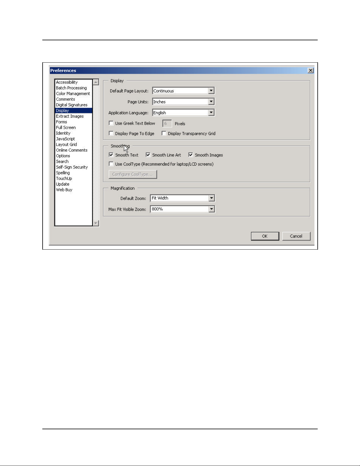
20 Preface
Figure 1 Acrobat Reader display setup selections
Text conventions
This guide uses these text conventions:
bold Courier text Indicates command names and options and text that you need to enter in
italic text Indicates file and directory names, new terms, book titles, Web
bold text Indicates command names, screen titles, options and text for a graphical
angle brackets (< >) Indicates a keyboard key press or simultaneous key presses, i.e.
P0609330 3.0
a command-line interface.
Example: Use the dinfo command.
Example: Enter show ip {alerts|routes}.
addresses, and variables in command syntax descriptions.
user interface (GUI).
<ENTER> or <CTRL j>
Page 27

Acronyms used in this guide
This guide uses these acronyms:
API Application Program Interface
ASM Analog station module
ATA (or ATA2) Analog Terminal Adapter
AWG American Wire Gauge
BIOS Basic Input Output System
BootP Bootstrap Protocol
BRI Basic Rate Interface
CAP Central Answering Position
COPS Common Open Policy Service
CSU Channel Service Unit
DASS2 Digital Access Signaling System Number 2
DECT Digital enhanced cordless telecommunications or Digital European
cordless telephone
Preface 21
DHCP Dynamic Host Configuration Protocol.
DN Directory Number
DNS Domain Name Service (DNS)
DPNSS Digital Private Network Signalling System
DTMF Dual Tone Multifrequency.
HTTP Hypertext Transfer Protocol
IETF Internet Engineering Task Force.
IP Internet Protocol
IPSec Internet Protocol Security
IPX Internetwork Packet Exchange
ISDN Integrated Services Digital Network
ISP Internet Service Provider
IVR Interactive Voice Response
LAN Local Area Network
MAC Media Access Control
MCDN Meridian Client Defined Network (PRI SL-1)
MIB Management Information Base
NAT Network Address Translation
NIC Network Interface Card
NOC Network Operations Center
OIT Optivity Integration Toolkit
Business Communications Manager Management Guide
Page 28

22 Preface
OSPF Open Shortest Path First
PBX Private Branch Exchange.
PCI Peripheral Component Interconnect Slot
PDD Partial Double Density
PPPoE Point-to-Point Protocol over Ethernet
PPTP Point-to-Point Tunneling Protocol
PRI Primary Rate Interface
PSTN Public Switched Telephone Network
QoS Quality of Service
RAS Remote access service
RIP Routing Information Protocol
SNMP Simple Network Management Protocol
TAPI Telephony Application Program Interface
TCP/IP Transmission Control Protocol/Internet Protocol
TE Terminal Equipment
TEI Terminal Endpoint Identifier
UDP User Datagram Protocol
Universal Dialing Plan
VoIP Voice over IP
VPN Virtual Private Networks
WAN Wide Area Network
P0609330 3.0
Page 29

How to get help
Your local distributor provides technical support for your Business Communications Manager
system or has access to that information through a Technical Service Center (TSC).
USA and Canada
Authorized Distributors - Technical Support
Telephone:
1-800-4NORTEL (1-800-466-7835)
If you already have a PIN Code, you can enter Express Routing Code (ERC) 196#.
If you do not yet have a PIN Code, or for general questions and first line support, you can enter
ERC 338#.
Website:
http://www.nortelnetworks.com/support
Presales Support (CSAN)
Preface 23
Telephone:
1-800-4NORTEL (1-800-466-7835)
Use Express Routing Code (ERC) 1063#
EMEA (Europe, Middle East, Africa)
Technical Support
Telephone:
00800 800 89009 or 33 4 9296 1341
Fax:
33 49296 1598
email:
emeahelp@nortelnetworks.com
CALA (Caribbean & Latin America)
Technical Support
Telephone :
1-954-858-7777
email:
csrmgmt@nortelnetworks.com
Business Communications Manager Management Guide
Page 30

24 Preface
APAC (Asia Pacific)
Technical Support
Telephone:
+61 388664627
Fax:
+61 388664644
email:
asia_support@nortelnetworks.com
Related publications
These documents provide further information about the Business Communications Manager,
related media bay modules, extension equipment, and system applications and software:
Business Communications Manager Programming Operations
Guide
All optional Business Communications Manager applications have installation and user guides
specific to that application. Refer to the Programming Operations Guide and Telephone Features
Programming Guide. These guides describe core system operational configuration and how to
program the Business Communications Manager equipment.
These guides provide programming for core telephony features and user features, such as:
• Voice telephony configuration for digital, IP, ISDN and radio-based telephones and equipment
over analog, digital, ISDN, and voice over IP (VoIP) trunks.
• How to use and program user telephony features at the telephone
• Companion Application Server software that controls the interface between the Business
Communications Manager system and the Companion wireless system (available for selected
regions)
• Networking DPNSS (upgrade) (requires keycode) provides private voice networking for the
UK Market.
• With Networking MCDN and ETSI Q.SIG Voice Networking (requires keycode) you can
network your Business Communications Manager system, or a number of Business
Communications Manager systems to a Meridian system. This lets the network use a common
numbering plan, as well as common voice messaging and auto attendant systems connected to
the Meridian.
• Data setup applications and protocols to configure the Business Communications Manager
system to be part of a LAN or WAN network. See the next section for specifics.
P0609330 3.0
Page 31

Preface 25
Call Detail Recording System Administration Guide
Call Detail Recording (no keycode required) records and reports call activity from the Business
Communications Manager. You can create reports from this information to help you manage
system usage effectively.
IP Telephony Configuration Guide
• i2001, i2 002, and i2004 IP telephones and the NetVision and NetVision Data telephones
require a combination of data and telephony settings to work with the Business
Communications Manager. These telephones can make or receive calls through either VoIP or
PBX lines.
• Nortel Networks i2050 Software Phone turns your PC into a telephone interface which
provides standard telephony operating features such as Voice Mail, Caller ID, and multiple
telephone lines or line appearances. This application requires Windows 2000, a full duplex
sound card, and a computer-telephony headset. This document describes what settings are
required to use this application with the Business Communications Manager. The i2050
Software Phone Installation Guide provides specific installation information.
• VoIP Gateway (requires keycode) converts the voice in a call into a packet format and sends
the call using an intranet trunk. With Business Communications Manager VoIP Gateway, you
can make calls over any intranet connected to the Business Communications Manager system.
Business Communications Manager Management Guide
Page 32

26 Preface
P0609330 3.0
Page 33

Chapter 1
Management Overview
This section is an introduction to the Business Communications Manager network-level
management concepts and techniques.
The management overview is divided into three categories.
Management oncepts and models
• “Network Administration Objectives” on page 27
• “Network Topology and Management Interfaces” on page 29
• “SNMP Network Management Concepts” on page 32
• “Network Management and Maintenance Applications” on page 33
• “Unified Manager” on page 34
Unified Manager
27
• “Using Unified Manager” on page 40
• “Unified Manager Maintenance Page Overview” on page 43
Management Guide overview
• “Management Guide Overview” on page 51
• “BCM Monitor overview” on page 52
• “Performance management overview” on page 53
• “Security management overview” on page 53
• “Backup and restore overview” on page 54
• “Troubleshooting and diagnostics activities overview” on page 55
Network Administration Objectives
Network operations center (NOC) responsibilities encompass the operation of the entire network
domain. Network administration is a complex task that requires intimate knowledge of the
construction and workings of the network environment.
NOC activities
• Monitoring routers, switches, hubs, and auxiliary backup systems (power supply, data)
equipment that comprise the enterprise data network.
• Monitoring network traffic trends and resolve network bottleneck problems.
Business Communications Manager Management Guide
Page 34

28 Chapter 1Management Overview
• Managing and allocating IP addresses and domain names, recording and providing remote
connectivity to the enterprise computing systems.
The descriptions and procedures in this guide that assist with service assurance:
• Monitoring the network for alarms and performance threshold
• Ensuring service network integrity
• Isolating, diagnosing and reparing faults
• Managing performance. NOC takes first call from the alarms and performs initial
troubleshooting of the problem. Monitor link status and view, provision, edit and audit
connections. Log into network elements. Monitor inventory. Monitor network performance
(performance threshold provisioning).
Network management model
The Business Communications Manager network management model defines the management
functions into layers that show the flow of management information between communicating
entities. The Business Communications Manager network mode figure illustrates the management
layers.
Figure 2 Business Communications Manager network model
Business & Policy Management Layer
• Policy assessment, definition & evolution
Network Management Layer
• Event & Alarm Mgmt
• Infrastructure access
• Performance & optimization
• Communications
• QoS Monitoring
Element Management Tools
• Troubleshoot events & alarms
• Backup & restore
Manageable Systems & Endpoints
• User applications & capabilities
• Event / alarm generation
• System data / traffic
System & Config
Management Layer
• Multi-site configuration
• Asset inventory mgmt
• Bulk MACs
• Enable/disable software keys
• Configuration & administration
• User access
• Threshold settings
• Software k eys
P0609330 3.0
Page 35

Chapter 1Management Overview 29
Network Topology and Management Interfaces
Business Communications Manager Unified Manager, Network Configuration Manager and
SNMP Network manager support the objectives and knowledge requirements of NOC network
administrators. These applications detect, observe and report on the state of the network elements
and the overall health of the network.
“Business Communications Manager enterprise network model” on page 30 shows a sample
Business Communications Manager enterprise network that illustrates the various
communications links to end devices and control consoles. The diagram also shows that the
physical enterprise network, conceptually, is segmented into domains.
• The Network Operations Center (NOC) domain represents the tools, equipment and activities
used to analyze and maintain the operation of the Business Communications Manager
network. Unified Manager and Network Configuration Manager provide the software
interface to perform network control and maintenance functions. The controller workstations
can be located across different enterprise sites.
• The BCM network domain represents one or more Business Communications Managers
networked through an enterprise LAN to one or more controller workstation. The Business
Communications Managers need not be co-located at the same site. The WAN represents an
adjacent network, external to the LAN.
• The VoIP and Wireless VoIP domains represent terminating IP devices.
Business Communications Manager Management Guide
Page 36

30 Chapter 1Management Overview
Figure 3 Business Communications Manager enterprise network model
NOC Domain
Network
Configuration
Manager (NCM)
Unified Manager
Workstation
SNMP Network
Manager
Workstation
BCM Network Domain
NCM
Server
NCM
Database
Network
Solutions
VoIP
Wireless VoIP
RS232 local interface
WAN
PSTN
V.90
Modem
SNMP Network
Manager Server
Remote
Dialup
Network management physical interfaces
Business Communications Manager offers alternatives on how to connect to, and access, the
Business Communications Manager unit and devices in the network (see “Business
Communications Manager physical interfaces” on page 31). Connectivity to the network and
Business Communications Manager depends on the network configuration and telephony
resources built in the system.
Physically, the Business Communications Manager network can be distributed geographically
across different sites. The network administrator must be able to access each BCM in the network.
Network administration personnel have the ability to configure, observe and control the operation
and performance of the Business Communications Manager through one of the available access
portals. These interfaces provide management access to the Business Communications Manager
(see Figure 4):
P0609330 3.0
Page 37

• WAN IP interface: WAN internet access (IP access through the Unified Manager interface)
The WAN interfaces use T1 (with CSU), V.35, X.21, PRI/BRI MBMs Dial on demand.
Establish a connectivity path provided from the corporate LAN network to the end-user’s
WAN network or ISP over another WAN device (e.g. router elsewhere on the enterprise
premises).
• V.90 Dial-up modem interface: (North America option only) The dial-up connection
interface is available for occasional use. Due to modest dialup speeds, and potentially large file
sizes, dial-up has limited use. For regular backup/restore and configuration tasks, use a higher
bandwidth connection for management access to the Business Communications Manager.
• Local RS232 serial interface (COM port): Local terminal emulation interface. The Business
Communications Manager platform base chassis has a serial RS232 port. The RS232 port
provides local terminal emulation connectivity to the BCM. This method is normally used
upon initial install. Use local connectivity to set the system’s IP address and other basic system
and networking parameters to enable the BCM for remote access. Alternatively, the RS232
port is used to establish a local connection to perform local maintenance activities in the event
of an IP network communications failure.
• LAN IP interface: local LAN port (IP access through the Unified Manager interface). The
LAN Ethernet interface transmits at 10/100 Mbps. Use IP over a LAN Ethernet interface.
Figure 4 Business Communications Manager physical interfaces
Chapter 1Management Overview 31
CTM 4
1 Aux 2 3 4
DSM 16+
1 2 3 4 1 2 3 4
StatusPower
21 3 4 5
WAN card (field upgrade) connects the Business Communications Manager system to the wide area network.1
V.90 Modem port (available in North America only) provides PSTN dial-up access to the BCM.
2
Local RS232 COM port provides a serial connection to a laptop for maintenance purposes. Also supports a
3
DB9 serial connection to a UPS for power monitoring (see UPS Installation and Configuration Guide).
45Ethernet port connector #2 provides access to internal local area network
Ethernet port connector #1 provides access to external local area network
CTM
DSM
DECT
Unpopulated
Business Communications Manager Management Guide
Page 38

32 Chapter 1Management Overview
SNMP Network Management Concepts
Your Business Communications Manager network uses several hardware devices and various
software applications. Network management software provides the ability to exercise control over
the network devices.
Refer to these descriptions:
• “Network management communication protocols” on page 32
• “SNMP network structure” on page 32
Network management communication protocols
The SNMP, HTTP, Telnet, and FTP protocols are fundamental to management of a network of
Business Communications Managers.
• SNMP (simple network management protocol): SNMP is application-layer software you use
to communicate with and control devices in your network.
• HTTP (hypertext transport protocol): HTTP is a communications protocol that lets users
establish a connection with a Web server and transmit HTML pages to a client browser. BCM
is a web-server. HTTP also allows transmission of other files required by an HTTP application.
• Telnet: Telnet is a terminal emulation communications protocol used on the Internet and TCP/
IP-based networks. Telnet allows a network administrator or user to use a local workstation to
log onto a remote computer and run a program. Telnet is part of the TCP/IP protocol.
• FTP (file transfer protocol): FTP is a protocol used to transfer files over a TCP/IP network
(Internet, Unix). With FTP you can log onto the network, list directories, and copy files from
other workstations/servers. FTP operations are performed by typing commands at a command
prompt or through an FTP utility running under a graphical user interface (GUI).
SNMP network structure
Network management objectives for the Business Communications Manager are based upon the
FCAPS network management model (fault, configuration, administration, performance, security).
To accomplish these objectives, the Business Communications Manager must have the ability to
provide appropriate feedback to the network administrator.
Network administrators use SNMP data do manage network performance, find and solve network
problems and plan for network expansion (see “Network Administration Objectives” on page 27.)
The Business Communications Manager network management system is composed of:
• SNMP network management stations (NMS): A console (server/workstation) through which
the network administrator performs network management activities upon managed objects.
The SNMP network manager server (workstation) is a physical control device equipped with
network management software that interfaces with the Business Communications Manager(s)
in your network.
P0609330 3.0
Page 39

Chapter 1Management Overview 33
• SNMP agents: SNMP agent software interfaces and handles interaction between the device
and the SNMP network manager workstation. SNMP agents are software modules resident in
network elements, in this case the BCM. The SNMP agent collects, stores and retrieves MIB
(management information base) data and forwards the information to the SNMP network
manager server.
• Network elements (managed devices): Hardware components such as computers, routers, and
terminal servers that are connected to networks.
• Managed objects: Hardware, configuration parameters or performance statistics that directly
relate to the operation of a device. Bridges, hubs, routers, or network servers are examples of
managed devices that contain managed objects.
• Management information base (MIB): The MIB is the software that defines the data reported
by the device and the extent of control. A virtual information store that contains a collection of
managed objects.
• Management protocol (SNMP): Used to transport management information between the
agents and console. Simple network management protocol (SNMP) is the standard
management protocol. An SNMP trap is a message format used by the SNMP agent to inform
the NMS of a system event.
Managed objects and agents illustrates the agent and object relationship in a network and how the
system provides event notification to the SNMP network manager workstation. Data passes from
SNMP agents (hardware/software processes that report activity in all network devices) to the
SNMP Network Manager server.
Figure 5 Managed objects and agents
Fault in
Device 1
SNMP Network Manager
Workstation/Server
Fault
SNMP
Messages
Network
SNMP
Messages
SNMP
Messages
Device 1
SNMP
Agent
Device 2
SNMP
Agent
Device n
SNMP
Agent
Network Management and Maintenance Applications
The tools and applications bundled with the BCM provide statistics and notifications of system
status and operation. There are three categories of network management applications that are
available and compatible for operation with the BCM or network elements:
MIB
MIB
MIB
Business Communications Manager Management Guide
Page 40

34 Chapter 1Management Overview
• BCM-specific tools and applications
• optional tools and applications
• third-party tools and applications
BCM-specific tools and applications
• Unified Manager (see also “Unified Manager” on page 34) is web-based configuration and
maintenance application bundled with the Business Communications Manager software.
Unified Manager is the single point of access for managing all programming for individual
BCM systems. Access to the Unified Manager is password protected, and is secure for both
enterprise customers and small to medium sized businesses. Administrators use Unified
Manager to quickly set up BCM telephony and data functions, as well as users, mailboxes, and
directory numbers.
• Network Configuration Manager (NCM) provides centralized configuration and system
management capabilities for a number of Business Communications Manager in a network.
This centralized functionality is required to enable multi-site Business Communications
Manager customers and channel partners to significantly reduce the cost of ownership of their
systems.
• BCM Monitor : Use this standalone diagnostic application to view system and IP telephony
information on individual Business Communications Manager units. Open several instances of
BCM Monitor to monitor several remote BCM systems on a single PC simultaneously. This
tool supports real-time debugging. You can also use BCM Monitor to save and process data at
a later time to generate system utilization and traffic reports.
Optional tools and applications
• Optivity Network Management System (ONMS): Use Optivity NMS to manage Nortel data
devices such as Baystack switches, BPS2000, Passport LAN switches, BayRS, and Alteon.
Integrate Unified Manager into the Optivity Network Management System (NMS) via the
Optivity Integration Toolkit (OIT). Enable BCM discovery, launch, and alarm integration into
Optivity NMS. Business Communications Manager appears as an element in an ONMS
network discovery diagram. BCM SNMP traps are displayed by ONMS, and Unified Manager
is launched from within Optivity.
Note: If you require an integrated Unified Manager/ONMS configuration, contact Nortel
Networks to confirm the correct interoperation of the current releases BCM and ONMS.
Unified Manager
Unified Manager, a web-based navigation tool, provides access to all operations and maintenance
programming functions on the Business Communications Manager system. Unified Manager
allows authorized administration personnel to monitor and control BCM functions from a single
site.
P0609330 3.0
Page 41

Chapter 1Management Overview 35
Unified Manager is the single point for managing all programming for individual BCM systems.
You can access Unified Manager locally via the LAN or WAN. Remote access is available via a
V.90 modem dialup. You can also access Unified Manager through a browser from across a WAN
or Internet connection.
Use Unified Manager to configure data and voice services on Business Communications Manager.
Unified Manager gives you data entry and performance tracking charts and tables for network
monitoring, access to alarm and event notifications and diagnostic information.
This section includes information about:
• “Using the Unified Manager main page buttons” on page 35
• “Using Unified Manager” on page 40
• “Logging off Unified Manager” on page 42
Using the Unified Manager main page buttons
When you access the Unified Manager main page (see “Unified Manager main page” on page 36 ),
several selections provide access to operations grouped under these functional categories:
• “Configure” on page 36
• “Wizards” on page 36
• “Installing clients” on page 38
• “CallPilot” on page 39
• “Documentation” on page 40
• “BRU” on page 40
• “Maintenance” on page 40
Business Communications Manager Management Guide
Page 42

36 Chapter 1Management Overview
Figure 6 Unified Manager main page
Configure
Access the Unified Manager programming interface for all services except those controlled by the
CallPilot and IVR services.
Wizards
When you install your system, you run the Quick Start Wizard to set up your system parameters.
This wizard is described in the Wizard help, that can be accessed after you from the Wizards page
of the Unified Manager.
Use the Wizards to perform Quick Start, Add Users, Edit DN Record Template, DN Renumber,
Network Update. See the Programming Operations Guide for more information.
The Wizards are self-co ntained task applications that you can use to speed up some configuration
tasks. You access the Wizards from the Wizards button on the first page of the Unified Manager.
See the Programming Operations Guide for more information.
P0609330 3.0
Page 43

Figure 7 Programming Wizards
Chapter 1Management Overview 37
Wizard
Quick Start
Add Users
Edit DN Record Template
DN Renumber
Network Update
Action
Initializes the system and sets up your basic system information.
This wizard is only run once, when your system is first set up.
Changes the telephony settings for a set of DNs or for a single
DN. You can define the settings in this Wizard, or you can use a
pre-defined template, from a local site or from a remote site,
created with the Edit DN Record Template wizard.
Selects Telephony User Templates and change and define the
user settings for telephones. The Telephony Template is stored
in a file for use with the Add Users Wizard.
Renumbers a range of DNs.
Updates your system data network settings any time after the
Quick Start Wizard, which does the initial network setup.
Business Communications Manager Management Guide
Page 44

38 Chapter 1Management Overview
Wizard
Quick Start
DECT Mobile Recording
DECT Configuration
Action
Initializes the system and sets up your basic system information.
This wizard is only run once, when your system is first set up.
Enables and disables mobile recording for one of the base
station ports.
Configures a DECT module. It also turns on one of the base
station ports to allow mobile recording (handset registration).
The DECT Wizards appear on the Wizards page only if there is
a DECT module installed and identified to the system. These
wizards are discussed in the DECT Installation and
Maintenance Guide.
Navigating the wizards
These are some helpful hints about how the wizards work, and how to use them.
• To open the online help, from the Programming Wizards screen click the Programming
Wizards Help link.
• You can move back and forth between screens in the wizards by clicking the Back and Next
buttons.
• You can revise your choices and entries on any of the wizard pages until you click the Apply
button. Once you click the Apply button, the system applies the selected configurations. The
user is presented with a confirmation box that provides the approximate timing of the process.
To check the status of the configuration, press the Refresh button. When the process is
complete, the title of the page has the word completed as part of the title.
Installing clients
After you set up the system and it is operating, you can add keycodes for any optional features you
want to install.
You access optional applications through the Install Clients button. Many applications require a
keycode. For information about how to set up these optional features, see the documentation for
each application.
With the install clients utility you can select and download multimedia and telecommunications
clients. Applications can require other components or software keys to be installed. Each
application page identifies if anything else is required.
Clients you can download
Applications
• Call Center and Multimedia Call Center
P0609330 3.0
Page 45

Chapter 1Management Overview 39
• CallPilot
• Interactive Voice Response (IVR)
• Desktop assistant, i2050 software phone, Personal Call Manager, NetVision Symbol phone
administrator
Toolkits
• CDR Client wrapper
• LAN CTE client
• TAPI 2.1 installation
• Unified Manager Java class library
Developer information
• Program description
• Developer categories
• Developer partners
Administrative tools
• Desktop assistant Pro E
• BCM Monitor
• SSH client
CallPilot
Click the CallPilot button to access CallPilot Manager, the CallPilot management application.
CallPilot Manager is a web-based application that you use to administer:
• Voicemail
• Call answering
• Auto Attendant
• Custom Call Routing
• Fax answering
• Call Center
• Message Networking
Note: Basic CallPilot functions are standard on the Business Communications Manager
and you define your region and basic settings when you run the Quick Start Wizard. See
the Programming Operations Guide for more information.
Business Communications Manager Management Guide
Page 46

40 Chapter 1Management Overview
Documentation
Click the Documentation button to find the information you require to help you understand and
configure your system to your specifications. The entire Business Communications Manager
documentation suite, plus a number of training panels, are included on your Business
Communications Manager computer, as well as on the CD that accompanied your system.
• Provides access to:
— Documentation on how to install hardware, configure and operate various BCM-specific
applications.
— Product overview
— Download Adobe Acrobat Reader
BRU
Click the BRU (Backup and Restore Utility) button to access BRU functionality. BRU provides a
way to back up your system data and configurations in the way that is most useful for your
purposes. Backed up data can be restored to the BCM if a system failure occurs, such as a
prolonged power outage. See System Backup and Restore (BRU) on page 381 for more
information.
Maintenance
The Maintenance button accesses a number of maintenance tools that let you determine the current
status of the various aspects of your Business Communications Manager system. For more
information see the description “Unified Manager Maintenance Page Overview” on page 43.
Using Unified Manager
Unified Manager is a web-based navigation tool you use to view and change configurations for the
Business Communications Manager system.
Most changes made with Unified Manager become part of current Business Communications
Manager programming when you select an item from the menu options. However, some changes
take effect after you exit the screen. If a programming error occurs, you must re-enter the original
programming.
For more information on how to use the Unified Manager interface, see the Programming
Operations Guide .
Understanding the navigation tree headings
The Unified Manager navigation tree contains five main headings that you use to access specific
areas of the Business Communications Manager system. These headings are:
P0609330 3.0
Page 47

Chapter 1Management Overview 41
(<IP address>)
Table 2 Navigation tree menu functions
Heading Programming
System Provides access to Licensing, Identification and Security subheadings. This includes a
form to enter keycodes, and a list of current supported services.
From the Security heading you can determine the level of security within and entering the
system. See Chapter9, “Security Management.
When you select the System heading, you can view system information such as your
system name and a description about which resources and services are available.
Selecting the System heading also enables Configuration, Performance, Fault, Logoff,
View, and Help. With these commands you can:
• enable/disable services
• access CPU and memory status
• access to the alarm banner, which displays totals of alarms
• access or refresh a system inventory list
• reboot the system or shut down operations
Resources Provides access for configuring data and telephony resources for Business
Communications Manager hardware setup. See the Programming Operations Guide as
well as in the DECT Installation and Maintenance Guide.
Services Provides access for configuring telephony and data networking services and various
other related services. Telephony information is discussed in the IP Telephony
Configuration Guide. System data configuration is discussed in the Programming
Operations Guide . This section also supports the information found in the CallPilot
documentation, and the documents for CDR Recording, LAN CTE, IVR, Doorphone,
Network administration, UPS Installation and Maintenance Guide, and DECT Installation
and Configuration Guide. To manually enable or disable the Telnet service, See
“Manually activating Telnet” on page 431.
Management Provides access to the User Manager, which you use to manage the users who have
Diagnostics Provides access to items you can use to generate and access statistics on different
access to the Unified Manage r (Chapter9, “Security Management), and to the Alarm
Manager, which is used to define why types of alarms get reported by the system. For
more information on alarms and SNMP traps, see Chapter2, “Fault Management
System.
system components. Business Communications Manager provides statistics, metrics
and event logs on resources and services to help you carry out system maintenance
activities.
System metrics information is contained in the programming section to which they apply.
See the Programming Operations Guide and the IP Telephony Guide.
Split DS30 configuration and double density configuration are located under the
Configuration menu of the MSC heading. These system features are discussed in the
Programming Operations Guide.
Business Communications Manager Management Guide
Page 48

42 Chapter 1Management Overview
Logging off Unified Manager
When you have finished a session on the Unified Manager, you need to log off correctly to protect
the integrity of the information you entered.
1 Choose BCM (<IP address>) at the top of the navigation tree.
The Logoff menu is enabled.
2 Click Logoff, then select Logoff.
A message appears that asks you to confirm your request to log off.
3 Click Yes to continue.
4 A second message appears reminding you to close your browser window after the system has
logged out. Click Yes to continue.
A Logoff progress bar appears. When it the logoff is complete, the browser display will revert
to the Login screen.
5 Click the Windows exit icon (top, right corner).
6 Click the Windows exit icon on the browser window displaying the Business Communications
Manager main menu.
Note: Exit both Unified Manager browser windows, even if you want to re-log on to the
Configuration area. After you exit both windows, you can reestablish a connection with
the Business Communications Manager and log on as usual.
Failure to log out of both browser windows can result in a failed attempt to re-enter the
Unified Manager Configuration section.
P0609330 3.0
Page 49

Chapter 1Management Overview 43
Unified Manager Maintenance Page Overview
The maintenance page is a dedicated maintenance area that provides access to several maintenance
tools and capabilities. Gathering these tools into one location provides the network administrator
with a single source for maintenance information, helping to reduce errors and contribute to
gaining overall serviceability efficiency.
Figure 8 summarizes the links through the maintenance page. Select any of the links in Figure 8 to
display a description of the maintenance function.
Figure 8 Unified Manager maintenance page paths
Maintenance page access
Support
Contact
Alarms and traps
Maintenance
System information
Order and enable optional components
Install optional components
Maintenance tools
Technical support contact screen
Alarms and traps screen
Shared drive tools
Attach to a shared volume
Detach a shared volume
Enable/Disable BCM drive shares
System interaction tools
Execute a command
Telnet session
Troubleshooting tools
IP network troubleshooting
Services & driver troubleshooting
DECT tools
Security
Miscellaneous
System information screen
Keycode retrieval screen
Install optional components screen
DECT tools
Uploading a certificate and a private security key
Reset UM server
Archlogs
Report-a-problem
wizard
Archlog scheduler Archlog schedule screen (page 1)
Archlog viewer
Archlog settings
Browse logs folder
Report-a-problem input screen
Report-a-problem application
Advanced application selection screen
Archlog viewer screen
Archlog configuration screen
Archlog browse logs folder screen
Business Communications Manager Management Guide
Page 50

44 Chapter 1Management Overview
Maintenance page access
Access the Maintenance page by clicking the Maintenance button on the Unified Manager main
page (see Figure6 on page36).
Tools and applications on the Unified Manager maintenance
page
Support Maintenance Archlog
Contacts System information Report a problem wizard
Alarms and traps Order & enable optional components Archlog scheduler
Install optional components Archlog viewer
Maintenance tools Archlog settings
Figure 9 Unified Manager Maintenance page selections
Browse logs folder
P0609330 3.0
Page 51

Chapter 1Management Overview 45
Support
Maintenance page support selections are:
• Contact
• Alarms and Traps
Contact
The contact screen displays the ITAS contact telephone numbers and contact instructions for all
regions.
Figure 10 Technical support contact screen
Alarms and traps
The alarms and traps screen provides a summary list of BCM component ID alarms.
Select one of the component ID alarm links to navigate to a full description of the alarm and
associated service (if any). For more information on alarms and traps, see Chapter2, “Fault
Management System.
Business Communications Manager Management Guide
Page 52

46 Chapter 1Management Overview
Figure 11 Alarms and traps screen
Maintenance
Maintenance selections are:
• System information
• Order & enable optional components
• Install optional components
• Maintenance tools
System information
The system information screen displays a summary of the software release and hardware inventory
currently installed on your BCM system.
P0609330 3.0
Page 53

Figure 12 System information screen
Chapter 1Management Overview 47
Order and enable optional components
The keycode retrieval search screen displays a search form you can use to:
• select the log on location to access the keycode retrieval system from
• select the product family for the keycodes you need to access
• search for keywords
Business Communications Manager Management Guide
Page 54

48 Chapter 1Management Overview
Figure 13 Keycode retrieval screen
Install optional components
On the install optional components screen you can:
• install the IPX routing protocol and services on the BCM
• install PPPoE to enable Point-to-Point over Ethernet capability on the BCM (requires a
keycode for installation). The PPPoE product is only available for BCMs that contain 2 LAN
adapters
When you select either of the above options, the system displays an installation wizard to guide
you through the installation process.
To display the install optional components screen, select Install optional components under the
maintenance category. The install optional components screen appears.
P0609330 3.0
Page 55

Figure 14 Install optional components screen
Chapter 1Management Overview 49
Maintenance tools
Use the maintenance tools screen to select the tools necessary for these application categories:
Application Tools
Shared drive • Attach to a shared volume
• Detach a shared volume
• Enable/Disable BCM Drive Shares
System interaction • Execute a command
• Schedule a command to execute
• Schedule a restart
• Telnet session
Troubleshooting • IP network troubleshooting
• Services and driver troubleshooting
DECT
(for more information see
the DECT Installation and
Maintenance Guide)
Security Upload certificate and private key
Miscellaneous Reset Unified Manager server
• Time synchronization
• Backup firmware
• Restore firmware
• Firmware upload
• Restore default configuration
• A-law/Mu-law companding scheme
Business Communications Manager Management Guide
Page 56

50 Chapter 1Management Overview
When you select a tool for any of the above applications, the system displays an installation wizard
to guide you through the installation.
To display the maintenance tools screen, select Maintenance tools under the maintenance
category. The maintenance tools screen appears.
Figure 15 Maintenance page maintenance tools screen
P0609330 3.0
Page 57

Management Guide Overview
This section summarizes the content of the Management Guide:
• “Fault management overview” on page 51
• “Service management overview” on page 51
• “Log management overview” on page 52
• “BCM Monitor overview” on page 52
• “Performance management overview” on page 53
• “Security management overview” on page 53
• “Backup and restore overview” on page 54
• “Troubleshooting and diagnostics activities overview” on page 55
Fault management overview
This section describes the alarm management system, system events and SNMP traps.
Administrators access alarms and perform fault analysis through the Unified Manager interface.
Use Unified Manager to configure the fault system.
Chapter 1Management Overview 51
For more information on how to manage system faults, see Chapter 2, “Fault Management
System,” on page 59.
This section also provides a correlation between the event source (SNMP traps), components, logs
and services. For more information see:
• “Component ID (alarm) summary information” on page 92
• “Component ID/SNMP Trap Error interpretation” on page 100
Service management overview
This section describes service manager capabilities in Unified Manager. This section also
describes the properties of the services in the Service Manager and associated alarm notifications.
To more information about services see Chapter 3, “Service Management System,” on page 251.
Use the Service Manager to access, assess or modify tervices running on Business
Communications Managers in your network. Services control the functionality of Business
Communications Manager. A service is a software process that controls interaction with Business
Communications Manager hardware devices, computing environment, telephony or your browser
interface.
Modification of any service has far-reaching effects on communications or event reporting
capability. Nortel Networks strongly recommends you consult with your support group before you
use the Service Manager.
Business Communications Manager Management Guide
Page 58

52 Chapter 1Management Overview
There are two categories of services:
• System level services: software processes that are critical to essential operating system-level
features (see “System-level service definitions” on page 258 )
• Nortel Networks configurable services: software processes that are critical to the operation
of Business Communications Manager software (see “Nortel Networks Configurable
Services” on page 285)
Log management overview
This section describes the Media Service Card (core telephony) logs. Because every components
of Business Communications Manager is logged, the system generates a large number of logs for a
variety of purposes. In the case of faults, consult the logs to help you to diagnose and correct the
problem.
Some logs run continuously and collect information to help you troubleshoot in the event of
system problems. You can disable some logs because the information collected may not be of
immediate or critical interest to maintain the system.
The system generates these MSC logs:
• MSC System Test Log: contains diagnostic test results, telephony events and alarms, audits. It
has a maximum size of 20 items, after which events are aged out to make room for new events.
• MSC System Administration Log : contains log on, and log off information. Has a maximum
of 10 entries. The 11th entry overwrites the 1st entry regardless of severity level.
• MSC Network Event log: contains T1 / PRI network interface events and alarms. This log has
a maximum of 10 events.
For more information on Business Communications Manager logs, see Chapter 4, “Log
Management,” on page 315 .
BCM Monitor overvie w
Business Communications Manager diagnostics involve both monitoring system status and
assessing performance.
For how to download and use the BCM Monitor, see Chapter 5, “BCM Monitor,” on page 335 .
BCM Monitor is an optional, standalone application you can use to view system and IP telephony
information for each Business Communications Manager. Open several instances of the
application on a single PC to monitor the corresponding Business Communications Manager
systems.
BCM Monitor supports real time troubleshooting and report generation. System administrators
and support personnel obtain key, real-time information to perform troubleshooting if necessary.
The system administrator accesses and saves information to generate system utilization and traffic
reports.
P0609330 3.0
Page 59

Chapter 1Management Overview 53
Using BCM Monitor to monitor your system status
With BCM Monitor you can see the current status of various parts of your system services.
Use BCM Monitor during troubleshooting to confirm current configurations, including CallPilot
applications and IP trunk information. You can find BCM Monitor under the Install Clients
button on the first page of the Unified Manager. The BCM Monitor section describes:
• “Starting BCM Monitor” on page 336
• “Using BCM Monitor to analyze your system status” on page 337
• “BCM Monitor statistical values (minimum and maximums)” on page 346
• “BCM Monitor information capture” on page 347
Performance management overview
The Unified Manager System Performance monitor provides detailed performance information for
the system and the system resources. The statistics are shown in charts or table format. If a
performance display is active, it is automatically updated with real-time performance information
in time increments that you set.
BCM performance and usage information can be queried by SNMP.
For more details on performance management, see Chapter 6, “Performance Management,” on
page 351.
Use these tools and procedures to monitor the Business Communications Manager system
performance :
• “System Performance tools and services” on page 351
• “Service Manager” on page 251
• “Base function tray system status display LEDs” on page 466
• “Using the Initialization menu to monitor system hardware” on page 470
• “Disk mirroring function” on page 471
• “Module Diagnostics” on page 433
If you determine through the use of the diagnostic tools, that a hardware problem exists, see the
Installation and Maintenance Guide for information on component replacement.
Security management overview
Web access to Business Communications Manager now uses SSL encryption for system security.
This includes the appearance of a security alert when you initiate a connection to the Unified
Manager using SSL, which indicates site validation of the default certificate.
Business Communications Manager Management Guide
Page 60

54 Chapter 1Management Overview
For more information on how to define security parameters for the system and for users, see
Chapter 9, “Security Management,” on page 407.
Security management topics
• “Understanding BCM SSL certificate properties” on page 410
• “Security Management Tools” on page 414
• “Setting the Interface Timeout” on page 415
• “Setting system security compatibility levels” on page 416
• “Managing access passwords” on page 417
• “Using the SSH client to access the text-based interface” on page 429
• “Manually activating Telnet” on page 431
• “Accessing Unified Manager through the firewall” on page 432
Backup and restore overview
Use the Backup and Restore Utility (BRU) to preserve the integrity of your Business
Communications Manager operating system software and configuration data. With BRU you can
perform a backup, restore or upgrade through a web connection. BRU is a single-user application.
Before you perform any substantial maintenance on the Business Communications Manager, save
your data to a safe storage module location elsewhere in the network. After hardware maintenance
is complete, restore the data to your Business Communications Manager.
For more information on how to operate the Backup and Restore utility, see Chapter 8, “System
Backup and Restore (BRU),” on page 381.
Backup and restore procedures
• “Accessing BRU” on page 396
• “Exiting from the backup and restore utility” on page 396
• “Resetting the BRU screen” on page 397
• “Adding a new volume” on page 397
• “Modifying a volume” on page 398
• “Deleting a volume” on page 398
• “Performing a backup using BRU” on page 399
• “Scheduling a backup” on page 402
• “Viewing scheduled backups” on page 404
• “Viewing a scheduled backup report” on page 404
• “Deleting a scheduled backup” on page 404
• “Performing a restore using BRU” on page 404
P0609330 3.0
Page 61

Chapter 1Management Overview 55
Troubleshooting and diagnostics activities overview
This section has information about diagnosing module line performance and device line issues.
This section also tells you how to perform a system startup, set identification parameters and
maintain telephony resources.
For more information on diagnostics activities, see Chapter 10, “Testing, Troubleshooting, and
Diagnostics,” on page 433 .
Troubleshooting and diagnostic activities topics
• “Module Diagnostics” on page 433
• “Problems with trunk or station modules” on page 436
• “Media Bay Module status” on page 437
• “Testing DTM Modules” on page 439
• “DTM CSU statistics” on page 441
• “Testing the DDI Mux” on page 444
• “Troubleshooting Telephone Connections” on page 448
• “Changing system identification parameters” on page 451
• “Changing the system domain” on page 451
• “Maintenance programming for telephony resources” on page 453
• “General Diagnostic Activities” on page 466
• “Emergency telephone does not function” on page 473
• “ATA 2 does not function” on page 474
• “Unified Manager Diagnostics” on page 475
• “Driver Debug diagnostics” on page 475
Business Communications Manager Management Guide
Page 62

56 Chapter 1Management Overview
P0609330 3.0
Page 63

Chapter 2
Fault Management System
Business Communications Manager fault management topics
• “BCM Fault Management Tools” on page 59
• “Alarm Management System” on page 60
• “Alarm Reporting System” on page 61
• “Accessing and configuring the Alarm System” on page 66
• “SNMP Traps” on page 75
• “Configuring an SNMP Community” on page 77
• “Configuring an SNMP Manager List” on page 81
• “Configuring an SNMP Trap Community List” on page 85
• “Alarm Analysis and Clearing Procedures” on page 89
• “Component ID (alarm) summary information” on page 92
• “Component ID/SNMP Trap Error interpretation” on page 100
• “Component ID alarm descriptions” on page 101
• “Events that cause a system restart” on page 250
59
BCM Fault Management Tools
Fault management activities range from system setup, monitoring and reporting to fault
identification, diagnosis and correction. The tools available to the BCM network administrator to
access alarms and perform fault analysis are:
• Alarm management using the Unified Manager Interface
• SNMP traps for remote fault management
You access alarms and perform fault analysis through Unified Manager.
Business Communications Manager Management Guide
Page 64

60 Chapter 2Fault Management System
Alarm Management System
Business Communications Manager tracks and generates approximately 700 different alarms.
Alarms can provide notification that a network interface is not behaving as expected, or that
certain anomalies in system operation have been detected, for example.
When the Alarm Management system is enabled, all BCM alarms are recorded in the NT Event
Log. Use the Unified Manager Alarm Banner to view alarms for each Business Communications
Manager. A subset of the alarm information pertaining to BCM core telephony can also appear at
the Alarm telephone, and in the MSC logs. Managing alarms within Unified Manager is described
in “Alarm Analysis and Clearing Procedures” on page 89.
Note: Assign the Alarm telephone in Feature settings under System programming.
Alarms have a higher severity than events. Attend to alarm codes before event messages
Alarm code information that is specific to Companion components is included in the
Windows NT Event Log.
Any information sent to the Windows NT event log can generate an SNMP trap.
All BCM alarms can also be sent to a remote management system through an SNMP trap. For how
to perform remote fault management of BCM SNMP traps, see Configuring an SNMP Community
on page 77.
An alarm may not appear until two minutes after it is triggered. If the system is powered off when
the alarm is triggered, the alarm does not appear until two minutes after the system is powered on.
For more information about see
BCM alarms “Alarm Analysis and Clearing Procedures” on page 89
BCM SNMP traps “SNMP Traps” on page 75
MSC logs “Media service card (core telephony) logs” on page 315
P0609330 3.0
Page 65

Chapter 2Fault Management System 61
Alarm Reporting System
This figure illustrates how Business Communications Manager manages system events.
Figure 16 Business Communications Manager events and alarms
Operating system, drivers
& applications
MSC
1
Telephony
Services
2
4
1
5
NT Event Log
Database
Alarm Manager
User defined
alarm filters
6
Alarm filters
SNMP Trap
Management
10
9
7
Alarm
database
NT SNMP
Extensible
Agent
SNMP
Traps
Alarm Banner
8
3
MSC Log
Database
Core telephony services running on the Media Services Card (MSC), generate event outputs (see
1
“Event sources” on page 62 ).
The system forwards BCM core telephony (MSC) events, including alarms, to the MSC telephony event
2
logs.
BCM telephony (MSC) event logs include the MSC System Test Log, MSC System Admin Log, and
3
MSC Network Event log. These logs capture all of the MSC (core telephony) system events (including
MSC alarms).
BCM core telephony (MSC) alarms are written into the NT Event log database. A subset of the
4
core telephony (MSC) events are also written into the NT Event log database.
The NT Event Log database captures events from all BCM components, including MSC alarm and
5
some MSC event information.
6
The Alarm Manager applies system filters based on configuration inputs.
The Alarm database captures all NT event information after system filtering is applied.7
Alarm Banner / Alarm Browser provides real-time display of alarms in Unified Manager.
8
The Alarm Manager SNMP subsystem applies filters to the BCM alarms based on user inputs about
9
severity levels and event sources.
BCM alarms meeting the SNMP trap criteria are forwarded to the SNMP trap reporting interface according
10
to the trap community list.
Alarm Browser
Business Communications Manager Management Guide
Page 66

62 Chapter 2Fault Management System
Event sources
All BCM components can be a source of BCM event information. An event is defined as a
notification of an error or anomaly in operation, or a condition that can lead to an error or anomaly.
The terms “event” and “alarm” are used interchangeably in the BCM environment.
Refer to “Business Communications Manager events and alarms” on page 61 when reviewing the
description.
• BCM events derived from the operating system, drivers, services and applications, are
captured in the NT Event Log (item 5).
• The BCM events are recorded in the BCM Alarm database (item 7) and displayed as alarms in
the Alarm Banner (item 8). See also “Alarm banner and alarm browser” on page 64.
• The BCM events, or alarms, can also be made available to remote fault management systems
as SNMP traps (item 10).
MSC events
Core telephony services, which run on the Media Services Card (MSC) (item 1 of “Business
Communications Manager events and alarms” on page 61), represent one of the major BCM
components that act as a source of events. Referred to as MSC events or core telephony events,
these events are assigned an MSC event id and an event priority from P1 to P9, where P9 is the
most severe. If an MSC event is serious enough to be considered an alarm, the system also assigns
the MSC event an MSC alarm ID.
Refer to “Business Communications Manager events and alarms” on page 61 when reviewing the
description.
• All core telephony (MSC) events, including telephony alarms, are recorded in a set of core
system telephony logs (items 2 & 3).
• All core telephony (MSC) events designated as alarms are also written into the NT Event log
(item 4). In most cases, the MSC alarm ID, assigned by the core telephony (MSC) service, is
reused as the NT Event ID .
• Some of the core telephony (MSC) events, which are not alarms, are also written into the NT
Event log, primarily MSC events of priority P5 and higher (item 4). MSC events of priority P4
and lower can be seen only in the MSC logs - see “MSC (core telephony) logs” on page 63).
MSC events that are visible to the alarm service can also generate SNMP traps.
Due to the interaction between the MSC system and the BCM alarm system, an event in the NT
event database that originates from the core telephony services (MSC) will have an NT event ID.
An event will also have an associated core telephony (MSC) services event ID, and possibly also
an MSC alarm ID.
MSC event and alarm conditions
• Software errors that do not affect system operation
• Software errors that affect system operation: feature failure dropped calls, or system resets.
P0609330 3.0
Page 67

Chapter 2Fault Management System 63
• Events caused by hardware-related problems, but are not of sufficient severity as to be an
alarm condition. Installers, however, may need to know of these events as they can indicate a
hardware problem (for example, bad messages received on a signalling channel) or a PSTN- or
private network-related problem (for example, no battery feed, no dial tone, invalid disconnect
sequence).
• Events that are not of sufficient severity to be an alarm condition, but where the problem is
related to system limits affected by system usage patterns, administration, or lack of resource.
Examples are running out of autodialler/speed dialer bins, LHD nodes, DTMF/dial tone
receivers. These events may not be apparent to users, but a degraded level of service will likely
result.
• Information events, concerning a user action, typically in **ADMIN or **CONFIG. (for
example, admin log cleared, user attempted to enter **ADMIN with wrong password).
• Permanent, service affecting events that an installer can fix. Typically these are also alarms,
but that is not a prerequisite. An example of the latter is the defaulting of a portion of
administration, without a cold start (installer action: readminister the data).
MSC (core telephony) logs
Refer to “Business Communications Manager events and alarms” on page 61 when reviewing the
descriptions.
• MSC logs (item 3) are maintained on the Media Services card, MSC, which is the telephony
side of the Business Communications Manager system.
• The MSC logs are a set of three logs: the MSC System Test, MSC System Administration, and
MSC Network Event log. These logs capture all core telephony (MSC) system events,
including alarms. For more information, see “Media service card (core telephony) logs” on
page 315.
• Note that core telephony (MSC) events, designated as MSC alarms, are sent to the NT Event
Log in addition to being recorded in the MSC (core telephony) logs (item 4). MSC events of
priority 5 (P5) and higher are sent to the NT Event log (item 4 ). MSC events are shown in the
BCM alarms under the Voice Software component ID.
Business Communications Manager Management Guide
Page 68

64 Chapter 2Fault Management System
NT Event log database
When the alarm service is enabled, all BCM alarms are recorded into the NT Event Log (item 5 of
“Business Communications Manager events and alarms” on page 61).
For more information about how to view NT Event Logs, see “Obtaining NT Event Logs from
Archlog” on page 332 .
Alarm manager
See “Business Communications Manager events and alarms” on page 61 when reviewing the
descriptions.
• The system forwards events from the NT Event log to the Alarm Manager.
• The Alarm Manager applies system filters based on configuration inputs.
• The events are recorded in the Business Communications Manager alarm database.
Alarm database
See “Business Communications Manager events and alarms” on page 61 when reviewing the
descriptions.
• The alarm database (item 7) holds a maximum of 5000 alarm records. The network
administrator configures the record capacity of the alarm database to a smaller size if required.
• Use the Alarm Manager batch archive function to archive the information in the alarm
database. Set the batch job parameters (day of the week and time) and file destination. For how
to configure and use the alarm manager, see Configuring Alarm Manager settings on page 70.
Alarm banner and alarm browser
The Alarm Banner and the Alarm Browser (item 8, “Business Communications Manager events
and alarms” on page 61) provide real-time information about events occurring in the Business
Communications Manager system.
Alarm system interfaces
• With the Alarm Banner window you can continually monitor the Business Communications
Manager system for alarms. For more information, see “Accessing the Alarm Banner to
monitor alarm notification” on page 68 .
• With the Alarm Browser window you can browse through a list of alarms and see detailed
information for each one. For more information, see “Accessing the Alarm Browser to analyze
alarm detail” on page 69 .
P0609330 3.0
Page 69

Chapter 2Fault Management System 65
• With Alarm Manager you can manage the collection and storage of alarm information. Use the
Alarm Manager to enable or disable sending of all or some types of SNMP traps. The Alarm
Backup Batch Job backs up old alarm records to an archive folder at scheduled time intervals.
For more information on how to use the Backup Batch Job, see “Configuring Alarm Manager
settings” on page 70.
BCM alarm severity
Alarm severity refers to a scale in which an alarm notification is categorized. The alarm severity
prescribes the degree of appropriate user intervention.
There are four alarm severity levels:
• Critical alarms indicate system problems that require immediate corrective action.
• Major alarms indicate system problems that require corrective action.
• Minor alarms indicate system problems that do not affect system performance and may or
may not require action.
• Warning alarms indicate system status changes that normally do no need any corrective
action.
Business Communications Manager Management Guide
Page 70

66 Chapter 2Fault Management System
Accessing and configuring the Alarm System
The Alarm Service works to generate SNMP trap event notifications. You must also enable and
configure SNMP traps.
Functions the Alarm Service performs
• monitoring Windows NT event logs for incoming events
• synchronizing Windows NT logs with Business Communications Manager alarm database
• receiving events (alarms) from other Business Communications Manager applications through
its API and logs the events in the Business Communications Manager database
• archiving alarm history based on the criteria defined in Alarm Manager
• monitoring the alarm configuration changes and updates SNMP trap agent and Alarm Service
Note: When the Alarm Service is enabled, Business Communications Manager
automatically archives the BCM Event logs. See “Enabling the alarm service” on page
67.
Note: The Alarm Service is disabled by default. You must enable the Alarm Service to
view alarms on the Alarm Banner. See “Enabling the alarm service” on page 67 .
Note: You must configure how the system handles SNMP trap notifications. Events that
arrive in the alarm database trigger an SNMP trap message to be generated. If you do not
configure SNMP traps, you will not obtain optimum alarm reporting capability.
P0609330 3.0
Page 71

Chapter 2Fault Management System 67
Enabling the alarm service
Use this procedure to enable the Alarm Service and view alarms on the Alarm Banner.
1 Access the correct Business Communications Manager in your network from the Unified
Manager workstation browser.
2 On th e Unified Manager navigation tree, click the Services key and select the Alarm Service
heading.
The Alarm Service Summary screen appears.
3 From the Status list box, change the status of the alarm service to Enabled.
Figure 17 Alarm service selection screen
4 Press the Tab key to save the settings.
Business Communications Manager Management Guide
Page 72

68 Chapter 2Fault Management System
Accessing the Alarm Banner to monitor alarm notification
Use the Alarm Banner to continually monitor the Business Communications Manager system for
faults or alarm conditions. The Alarm Banner stays active on your desktop for quick access. The
banner displays color codes to represent the alarm severity and the number of alarms for each
severity level. The Alarm Banner displays alarms in real time.
Note: You must enable alarm service before the Alarm Banner will function.To enable
the alarm server, see “Enabling the alarm service” on page 67.
To access the Alarm Banner
1 Access the correct Business Communications Manager in your network from the Unified
Manager workstation browser.
2 On the Unified Manager navigation tree select the System heading.
3 From the Fault menu select Alarm Banner.
The Alarm Banner appears.
Figure 18 Alarm banner
4 Select any color-coded alarm button to view a report of active alarms.
The Alarm Browser appears. See “Accessing the Alarm Browser to analyze alarm detail” on
page 69 for more information.
P0609330 3.0
Page 73

Chapter 2Fault Management System 69
Accessing the Alarm Browser to analyze alarm detail
With the Alarm Browser you can access and detect an alarm occurring on the system, and display
detailed information on each alarm to assist you to perform corrective action, if needed.
See the section “Alarm Analysis and Clearing Procedures” on page 89 for a detailed explanation of
how to navigate through the alarm clearing process and the descriptions in this guide.
To access the alarm browser and alarm detail screen
1 Access the correct Business Communications Manager in your network from the Unified
Manager workstation browser.
2 On the navigation tree click the System heading.
3 On the Fault menu click Alarm Banner.
The Alarm Banner appears.
4 Select any color-coded alarm buttonto display a report of active alarms. Select ALL (white
button) to browse through the complete list of system alarms, regardless of the severity level.
The alarm browser screen appears.
5 Select the row corresponding to the alarm for which you want detailed information.
6 On the Alarm Browser, click the Actions menu and select Display Details.
The Alarm Details screen appears. The Alarm Details screen is a read-only display.
Business Communications Manager Management Guide
Page 74

70 Chapter 2Fault Management System
Figure 19 Alarm browser and detail screen
7 Close the Alarms Details screen and the Alarm Browser when you are finished viewing the
alarms for this severity.
Configuring Alarm Manager settings
With Alarm Manager you can manage how you collect and store alarm information. With the
Alarm Manager you can set different collection parameters for the Alarm Database. You can use
the Alarm Manager to enable or disable the sending of all or some types of SNMP traps. The
Alarm Manager provides the Alarm Backup Batch Job, which backs up old alarm records to an
archive folder at a scheduled time.
To configure Alarm Manager settings
1 On the navigation tree, click the Management key and click the Alarm Manager heading.
P0609330 3.0
Page 75

Figure 20 Alarm database screen
Chapter 2Fault Management System 71
2 Use the information in this table to configure the Alarm Database.
Table 3 Alarm Database settings
Attribute Action
Maximum Number
Record
Kept Timer (days) Set the number of days that the records remain in the database before the records are archived.
Resync Timer
(seconds)
Set the maximum number of records that the alarm database stores. The default is 0 (no limit).
The range is from 0 to 5000 records. If you enter 0, there is no limit to the number of records.
When the number of records reaches the maximum, the earliest record is removed to make
room for the new alarm record.
Set, in seconds, the interval at which the alarm service initiates a synchronization operation with
the Business Communications Manager's internal event logs. This synchronization is in addition
to the normal synchronization operations triggered by the arrivals of new events.
Business Communications Manager Management Guide
Page 76

72 Chapter 2Fault Management System
Table 3 Alarm Database settings (Continued)
Attribute Action
Archive Location Enter the path to the directory where the archives of alarm information are kept.
The default path is: d:datafiles\nortel networks\unified manager\archive\.
Nortel Networks highly recommends that you do not change this path from it default value.
An archive of the alarm information is made when an Alarm Backup Batch Job is run or when the
Alarm Service is started. During an archive operation, the alarm database is copied to the
archive location and the alarm database is then emptied.
During an archive operation, the Business Communications Manager's internal event logs are
also copied to the archive location and the event logs are then emptied. The file names of these
internal event log archives are:
System Event Log SystemLogYYMMDDHHMM.evs
Application Event LogApplicationLogYYMMDDHHMM.evs
Security Event LogSecurityLogYYMMDDHHMM.evs
Where:
YY is the year the archive was created
MM is the month the archive was created
DD is the day the archive was created
HH is hour the archive was created
MM is the minute the archive was created
3 Press the TAB key to save your settings.
4 Click the SNMP Trap tab.
P0609330 3.0
Page 77

Figure 21 SNMP Trap screen
Chapter 2Fault Management System 73
5 Use the information in this table to configure the SNMP Trap.
Table 4 SNMP Trap settings
Attribute Action
Traps Enabled Enable or disable the sending of SNMP traps when a new event arrives in the alarm database.
Information
Events
Forwarded
Warning Events
Forwarded
Error Events
Forwarded
Source
Exclusion List
Enable or disable sending SNMP traps when an “Information” event arrives in the alarm database.
If you have auto SNMP trap dial out set up, and the value for 'Traps Enabled' is 'Yes', setting
"Information Events Forwarded" to "Yes" causes the BCM to repeatedly redial the trap client.
Always set "Information Events Forwarded" to "No" when SNMP trap dial out is set up.
If the name of a demand dial interface is selected as 'Interface' (when you add/modify a trap
community entry) and the 'Traps Enabled' field value is 'Yes', Nortel Networks recommends you
specify the value of the 'Information Events Forwarded' field as 'No'. If you specify a value of “Yes”,
the BCM will constantly redial to the trap client.
Note: Win dows 95/98 is not supported on a receiving system for the 'SNMP trap dialout' feature.
Enable or disable sending SNMP traps when a “Warning” event arrives in the alarm database.
Enable or disable sending SNMP traps when an “Error” event arrives in the alarm database.
Add, in a comma-separated format, a list of event sources from which SNMP traps must not be
generated. The source exclusion list prevents you from receiving SNMP traps which have no
meaning to you.
Business Communications Manager Management Guide
Page 78

74 Chapter 2Fault Management System
6 Press the TAB key to save your settings.
7 Click the Alarm Backup Batch Job tab.
Figure 22 Alarm Backup Batch Job screen
8 Use the information in this table to configure the Alarm Backup Batch Job.
Table 5 Alarm Backup Batch Job settings
Attribute Action
Batch Job Start or stop a scheduled batch backup to an archive folder. The Alarm Backup Batch Job uses the
Schedule Day Set the day for the backup.
Schedule Time Set the time for the backup.
Kept Timer value from the Alarm Database screen to determine when to archive an alarm record.
Tips
Before you change the day or time, or both, you must first stop the batch job, make your changes,
and then start the batch job again.
9 Press the TAB key to save your settings.
P0609330 3.0
Page 79

SNMP Traps
A trap is a signal that tells a program that an event occurred in the system. When a program
receives a signal, a specific set of activities take place.
The SNMP system enables SNMPv1 traps to be generated based on all or a subset of NT Events
generated on the Business Communications Manager. Any information sent to the BCM Windows
NT event log and shown in the Alarm Banner and Alarm Browser can generate an SNMP trap.
SNMP traps received from Business Communications Manager contain descriptions of the alarms
that occur in the system. Additionally, SNMP generic traps such as coldStart, linkDown, linkup,
authenticationFailure, are also generated from the Business Communications Manager, depending
on the user’s configuration.
For the BCM to generate SNMP traps, you must configure how the system handles SNMP trap
notifications. When SNMP is enabled, events arriving in the alarm database trigger an SNMP trap
message to be generated. Use the alarm manager to enable or disable sending of all or some types
of SNMP traps.
The trap format is specified in the BCM “Small Site Event MIBs” on page 488 and is captured and
viewed through any standard SNMP fault monitoring framework or trap watcher (see
“Management Information Base (MIB) System).
Chapter 2Fault Management System 75
BCM alarm and SNMP trap list
The complete set of BCM Alarms and SNMP traps is provided (see “Component ID (alarm)
summary information” on page 92 ).
To view the BCM Alarms list
1 Access the Unified Manager Maintenance page.
2 Click the Alarms and Traps link.
The Alarms and Traps screen displays a list of the events (see “Component ID (alarm)/
eventSource (trap) summary” on page 92).The events are organized by event source.
3 Contact your Business Communications Manager Nortel Networks Systems Engineer,
Services organization, or PLM and request a list in Excel spreadsheet format.
Business Communications Manager Management Guide
Page 80

76 Chapter 2Fault Management System
Alarm banner, NT event database, and SNMP trap correlation
Although the same events (alarms) that are reported in the Alarm System are ade available
remotely via SNMP traps and recorded in the NT Event logs, the terminology used for severity
levels is not the same.
Refer to the table Alarm banner, NT Event and SNMP Trap Severities or Types to interpret the
severity for each type of notification The terminology for severity levels between the NT Event log
and in the Alarm Banner is not identical.
Table 6 Alarm banner, NT Event and SNMP trap severities or types
Alarm priority Alarm Banner NT Event SNMP Trap Type
High critical Error Error
Medium major or minor Warning Warning
Low warning Information Information
Refer to the table SNMP Trap Types to interpret the severity for each type of notification. The
mapping between alarm severity levels and SNMP trap types (or 'specific-trap' code) is
summarized in the table.
Table 7 SNMP trap types
Alarm Severity SNMP Trap Type (specific-trap code)
critical eventError (3)
major eventWarning (2)
minor eventWarning (2)
warning eventInfo (1)
The BCM Alarm system denotes the source of a BCM alarm as “Component ID”, whereas the
SNMP system denotes the source of the same information as a trap of source “eventSource”. The
terminology used in this document of Component ID (alarm )/ eventSource (trap) is intended to
show that these two systems call the same information by a different name.
SNMP trap filtering
Trap filtering is done on Business Communications Manager using a source exclusion list and
severity levels of Error, Warning and Info. In this way, traps of type “error” (or severity level
critical) are forwarded according to the trap community list. The trap filters limit the volume and
type of SNMP information, and let you control essential information transferred on the network.
To set the filters
1 On the Unified Manager navigation tree, click the Management key and the Alarm Manager
P0609330 3.0
Page 81

Chapter 2Fault Management System 77
heading.
2 Click the SNMP trap tab.
3 Use the list boxes on the SNMP Trap screen to set the filters for SNMP traps.
SNMP guidelines
The SNMP service in Business Communications Manager re sponds to requests from management
stations, generates SNMP traps corresponding to events and reports to trap subscriber stations.
Use these SNMP guidelines
• Set read-only and read-write community names.
• Set a list of permitted managers. When set, the agent responds to SNMP managers requests
from those IP hosts only.
• An empty list of permitted managers implies that the agent responds to requests from anyone.
• Set trap communities. Each trap entry identifies the community name that must be used and
the manager addresses.
• Enable or disable sending authentication traps.
• Enable or disable the SNMP agent.
About defining SNMP trap destinations
SNMP trap destinations can be:
• a community list specifying community name and access privileges
• a manager list specifying SNMP manager IP addresses, that is, SNMP managers allowed to
make SNMP queries to the Business Communications Manager
• a trap community list that specifies destinations to which SNMP traps should be sent if SNMP
traps are enabled
Although no specific limit is set for the number of trap communities, Nortel Networks
recommends that you limit the number of trap communities to a maximum of 5. Limiting the
number of trap communities ensures that system performance does not degrade.
Configuring an SNMP Community
Use the procedures in this section to configure the Business Communications Manager to send
SNMP messages to an SNMP workstation.
• “Configuring SNMP summary attributes” on page 78
• “Adding a community to an SNMP community list” on page 79
• “Modifying an SNMP community list” on page 81
Business Communications Manager Management Guide
Page 82

78 Chapter 2Fault Management System
• “Deleting an SNMP community” on page 81
Configuring SNMP summary attributes
1 Access the correct Business Communications Manager in your network from the Unified
Manager workstation browser.
2 On the Unified Manager navigation tree click the Services key and the SNMP heading.
The SNMP Summary screen appears.
Figure 23 SNMP summary screen
3 Configure the SNMP summary attributes.
Table 8 SNMP Summary attributes
Attribute Action
Description View the description of the SNMP agent.
Version View the version of the SNMP agent.
Status Enable or disable the SNMP agent.
Authentication
Failure Traps
P0609330 3.0
Disable authentication failure traps.
When enabled, the SNMP agent sends authentication failure traps if there is an authentication
failure. Authentication failures happens if an SNMP manager application provides an incorrect
community string or performs an operation that is not permitted for a community.
Page 83

Chapter 2Fault Management System 79
Adding a community to an SNMP community list
1 Access the correct Business Communications Manager in your network from the Unified
Manager workstation browser.
2 On the Unified Manager navigation tree click the Services key and the SNMP heading.
The SNMP Summary screen appears.
3 Click the Community List tab.
The Community List screen appears.
4 From the Configuration menu click Add Community.
The Community List dialog box appears.
Figure 24 Community list screen
Business Communications Manager Management Guide
Page 84

80 Chapter 2Fault Management System
5 Configure the Community List attributes.
Table 9 SNMP Community List attributes
Attribute Action
Community List
(C#)
Community Name Specify the name of the community that the individual managers use to interact with this agent.
Access
Permission
Specify the entry name used as a key to uniquely identify an individual community entry on the
SNMP agent. Its value must follow certain conventions. It must have the prefix C followed by a
unique number that identifies the community name entry on the agent. For example, C2 is a valid
value. While adding, specify non-recurring values for the unique number.
While adding, if you specify an existing community entry name, it modifies the existing community
entry. Using non-sequential numbers results in automatic reassignment of sequential numbers.
While modifying a community entry, you can't change the name. The community entry name
does not have any significance other than to identify an entry.
The name is case sensitive.
The default community names are public and Private.
If there are no community names listed, then all community names are accepted.
All the community names are global to the agent. In other words, you cannot associate a specific
community name with a single management station.
Specify the read and write access for this community. Available options are:
READ-ONLY and READ-WRITE
The default value is READ-ONLY.
6 Click the Save button.
P0609330 3.0
Page 85

Chapter 2Fault Management System 81
Modifying an SNMP community list
1 Access the correct Business Communications Manager in your network from the Unified
Manager workstation browser.
2 On the Unified Manager navigation tree click the Services key and click the SNMP heading.
The SNMP Summary screen appears.
3 Select the Community List tab.
The Community List screen appears.
4 Select the community you want to modify.
5 On the Configuration menu click Modify Community.The Community List dialog box
appears.
6 Modify the Community attributes as required.
7 Click the Save button.
Deleting an SNMP community
1 Access the correct Business Communications Manager in your network from the Unified
Manager workstation browser.
2 On the Unified Manager navigation tree click the Services key and click the SNMP heading.
The SNMP Summary screen appears.
3 Select the Community List tab.
The Community List screen appears.
4 Select the community you want to delete.
5 On the Configuration menu select Delete Community.
A message appears that asks you to confirm the deletion.
6 Click the Yes button.
The community is deleted from the list.
Configuring an SNMP Manager List
Use the procedures in this section to add, modify or delete SNMP manager information in the
Manager List.
• “Adding a manager to the SNMP manager list” on page 81
• “Modifying an SNMP manager” on page 84
• “Deleting an SNMP manager” on page 84
Adding a manager to the SNMP manager list
1 Access the correct Business Communications Manager in your network from the Unified
Manager workstation browser.
Business Communications Manager Management Guide
Page 86

82 Chapter 2Fault Management System
2 On the Unified Manager navigation tree click the Services key and click the SNMP heading.
The SNMP Summary screen appears.
3 Click the Manager List tab.
The Manager List screen appears.
4 On the Configuration menu click Add Manager.
The Manager List dialog box appears.
Figure 25 Manager list screen
5 Configure the Manager List attributes.
Table 10 SNMP Manager List attributes
Attribute Action
Manager List
(M#)
P0609330 3.0
Specify the entry name used to identify an individual manager entry on the SNMP agent. Its value
must follow certain conventions. It must have the prefix M followed by a unique number that
identifies the manager entry on the agent. For example, M2 is a valid value. While adding, specify
non-recurring values for the unique number.
While adding, if you specify an existing manager entry name, it modifies the existing manager
entry. Using non-sequential numbers results in automatic reassignment of sequential numbers.
While modifying a manager entry, you cannot change the name. The manager entry name
uniquely identifies an entry.
Page 87

Table 10 SNMP Manager List attributes (Continued)
Attribute Action
Chapter 2Fault Management System 83
Manager IP
Address
6 Click the Save button.
Specify the IP Address of the SNMP Manager station corresponding to this entry. If no manager
entries are created, the Business Communications Manager device accepts SNMP requests
from all stations. If there is a list of manager entries, Business Communications Manager base
unit accepts SNMP requests from the IP Addresses specified in the list.
Business Communications Manager Management Guide
Page 88

84 Chapter 2Fault Management System
Modifying an SNMP manager
1 Access the correct Business Communications Manager in your network from the Unified
Manager workstation browser.
2 On the Unified Manager navigation tree click the Services key and click the SNMP heading.
The SNMP Summary screen appears.
3 Click the Manager List tab.
The Manager List screen appears.
4 Highlight the manager you want to modify.
5 On the Configuration menu select Modify Manager.
The Manager List screen appears.
6 Modify the manager attributes.
7 Click the Save button.
Deleting an SNMP manager
1 Access the correct Business Communications Manager in your network from the Unified
Manager workstation browser.
2 On the Unified Manager navigation tree click the Services key and click the SNMP heading.
The SNMP Summary screen appears.
3 Click the Manager List tab.
The Manager List screen appears.
4 Highlight the manager you want to delete.
5 On the Configuration menu select Delete Manager .
A message appears to confirm the deletion.
6 Click the Yes button.
P0609330 3.0
Page 89

Chapter 2Fault Management System 85
Configuring an SNMP Trap Community List
Use the procedures in this section to add, modify or delete information within the SNMP trap
community list.
• “Adding a trap community to the SNMP community list” on page 85
• “Modifying an SNMP trap community” on page 87
• “Deleting an SNMP trap community” on page 87
Adding a trap community to the SNMP community list
1 Access the correct Business Communications Manager in your network from the Unified
Manager workstation browser.
2 On the Unified Manager navigation tree click the Services key and click the SNMP heading.
The SNMP Summary screen appears.
3 Select the Community List tab.
The Community List screen appears.
4 On the Configuration menu select Add Trap Community.
The Trap Community List dialog box appears.
Figure 26 Trap Community list screen
Business Communications Manager Management Guide
Page 90

86 Chapter 2Fault Management System
5 Configure the Trap List attributes.
Table 11 SNMP Trap List attributes
Attribute Action
Trap List (T#) Specify the entry name used to identify an individual trap community entry on the SNMP agent.
Its value must follow certain conventions. It must have the prefix T followed by a unique number
that identifies the trap community entry on the agent. For example, T2 is a valid value. While
adding, specify non-recurring values for the unique number.
While adding, if you specify an existing trap community entry name, it modifies the existing trap
community entry. Using non-sequential numbers results in automatic reassignment of sequential
numbers. While modifying a trap community entry, you can't change the name. The trap
community entry name does not have any significance, other than to uniquely identify an entry.
Community Name View the community name. The community name is case sensitive and encoded in each trap
Manager IP
Address
Interface Specify the method to route SNMP traps to the SNMP trap collector.
message. This name cannot be in the Community List.
Specify the IP addresses of the SNMP trap subscriber stations. If you have too many IP
addresses in the trap community list, the SNMP service may degrade system performance.
The IP address must correspond to the PC where the trap collector software is installed.
Do not use the dynamic IP address that the PC receives when the dial-up link activates (as the
BCM initiates dialing). Using the dynamic IP address causes the removal of the required static
route.
If the trap collector is on the same subnet as one of the BCM LAN or WAN interfaces, select
'RouterAssigned' as the Interface value. The RRAS decides how to route the packet to the trap
collector according to its current routing table.
If you want to let the BCM send trap packets to the trap collector via the dialup interface, select a
demand dial interface as 'Interface'. The BCM automatically adds (under IP routing) a static route
for the trap collector that points to the dial-out V.90 modem or ISDN interface. Configure a trap
community entry with the trap collector IP address as the trap destination. Select
'RouterAssigned' or one of the dial-out interfaces listed in the drop-down list.
Types of communication links are:
• Select RouterAssigned: The route for the trap destination is automatically determined and
handled by the RRAS. Enter the IP address of the trap collector in the Manager IP Address
field.
• V.90 Dial-out: The interface is specified through Resources/dialup/V.90/Modemtrapdialout.
The BCM will automatically dial-out to the SNMP trap collector telephone number. Specify the
dial-out information under the V.90 Link Parameters tab. The Modembackup is not used for
the auto SNMP trap dial-out feature.
• ISDN BRI (Europe/North America): The interface is specified through Resources/dialup/
ISDN. The BCM will automatically dial-out to the SNMP trap collector phone number.
• ISDN PRI (Europe): The interface is specified through Resources/dialup/ISDN. The BCM will
automatically dial-out to the SNMP trap collector phone number.
6 Click the Save button.
P0609330 3.0
Page 91

Chapter 2Fault Management System 87
Modifying an SNMP trap community
1 Access the correct Business Communications Manager in your network from the Unified
Manager workstation browser.
2 On the Unified Manager navigation tree click the Services key and click the SNMP heading.
The SNMP Summary screen appears.
3 Click the Trap Community List tab.
The Community List screen appears.
4 Highlight the list you want to modify.
5 On the Configuration menu select Modify Trap.
The Trap Community List screen appears.
Figure 27 Modify trap community dialog box
6 Modify the trap community attributes.
7 Click the Save button.
Deleting an SNMP trap community
1 Access the correct Business Communications Manager in your network from the Unified
Manager workstation browser.
Business Communications Manager Management Guide
Page 92

88 Chapter 2Fault Management System
2 On the Unified Manager navigation tree click the Services key and click the SNMP heading.
The SNMP Summary screen appears.
3 Click the Trap Community List tab.
The Community List screen appears.
4 Highlight the list you want to delete.
5 On the Configuration menu select Delete Community.
A message appears that asks you to confirm or cancel the deletion.
6 Click the Yes button.
The SNMP trap community list is deleted from the database.
P0609330 3.0
Page 93
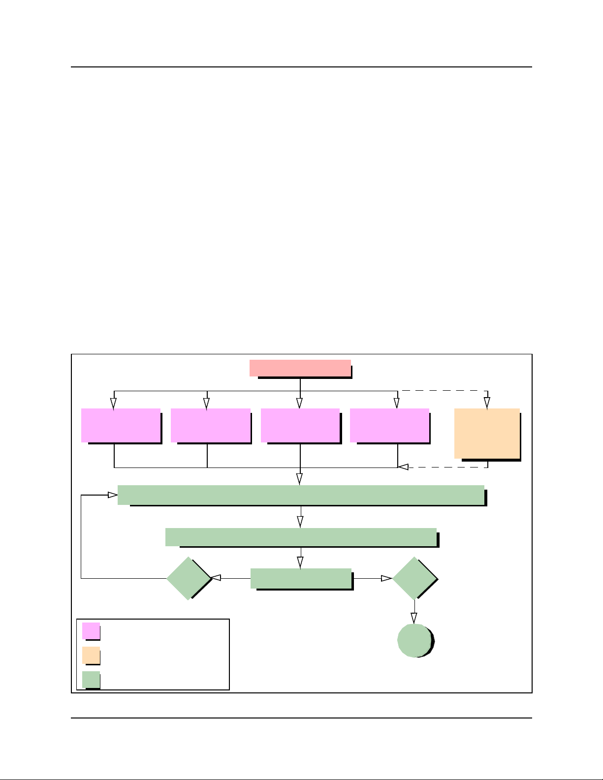
Chapter 2Fault Management System 89
Alarm Analysis and Clearing Procedures
Use the information in this section to identify, analyze and clear alarm events. This section
describes alarm messages and appropriate, associated maintenance activities (see the Alarm
clearing flow chart below.). Use the information in this section as a reference to interpret and act
upon event notifications from your alarm interface.
Unified Manager tools for detecting events that affect system
performance or function
• The Alarm Banner and Alarm Browser. These are the primary Unified Manager alarm
detectiontools.
• The phone alarm (if configured) provides both a visual and audible indication of an MSC
alarm event.
• The event logs displayed through the SNMP trap watcher provide supporting information or as
an alternative event reporting tool.
• The system test log provides supporting alarm information (for MSC events only).
Figure 28 Alarm clearing flow chart
Examine Alarm
Banner
Locate alarm event in Component ID (alarm)/eventSource (trap) summary on page 92
Routine monitoring process
Alternative monitoring process
Examine Alarm
Follow recommended action indicated in alarm description
Yes Other alarm?
Browser
Alarm event
Examine Alarm
Phone - MSC
Event
Examine
SNMP trap
Examine
System test
logs (MSC
events only)
No
End
Analysis & Resolution process
Business Communications Manager Management Guide
Page 94

90 Chapter 2Fault Management System
SNMP Event Messages
SNMP Trap notifications (messages) are displayed in your SNMP trap watcher.
SNMP event messages are generated when
• a system level service is activated or stopped
• a Nortel Networks configurable service is activated or stopped
SNMP events severity levels
• Error
• Warning
• Information
Using the component ID and event ID summary table s
The Alarm System shows the source of a BCM alarm as “Component ID”, whereas the SNMP
system shows the source of the same information as a trap of source “eventSource”. The
terminology used in this document of Component ID (alarm) / eventSource (trap) is intended to
show that these two systems call the same information by different names.
Use the table “Component ID (alarm)/eventSource (trap) summary” on page 92 to navigate to the
SNMP event displayed in your SNMP trap watcher.
Alternatively, use “Component ID alarms/eventSource (Trap) by event ID” on page 95 to identify
SNMP event ID and display the associated SNMP trap message and appropriate maintenance
activity.
Alarm description information
• associated service name
• event ID number
• alarm interpretation and corrective actions
• associated logs
To use the alarm summary table
1 Examine the alarm name shown in the Alarm Browser.
2 Select the corresponding link shown in “Component ID (alarm)/eventSource (trap) summary”
on page 92 under Alarm name.
The alarm description is displayed.
“Component ID (alarm)/eventSource (trap) summary” on page 92 also displays the service
associated with the alarm.
P0609330 3.0
Page 95

Chapter 2Fault Management System 91
3 Select the associated service name link to display the service description (see “Service
Definitions” on page 257 ).
4 Select the Return to table link to display the alarm summary table to select another alarm or
service description.
Business Communications Manager Management Guide
Page 96

92 Chapter 2Fault Management System
Component ID (alarm) summary information
Use the information displayed in this table to search for an alarm by the Component ID. Use the
table to display the Component ID alarm description and to determine the cause of an alarm/trap
and the appropriate maintenance activity.
Use the table to go to the descriptions you require:
• Click a link in the Component ID link (alarm)/eventSource (trap) column to review the alarm/
trap description.
• Click a link in the Associated Service column to review the service associated with the
Component ID (alarm). For example, discontinuation of a service or dependant service can
trigger an event notification or SNMP Trap for a specific Component. For detailed descriptions
of services see Chapter3, “Service Management System .
• Use Component ID alarms/eventSource (Trap) by event ID to search for a Component ID
(alarm) by the associated Event ID.
Table 12 Component ID (alarm)/eventSource (trap) summary
Component ID (alarm) /
eventSource (trap)
Atapi None SAM None
Autochk None Save Dump None
BCMAmp None Security EventLog
Browser Computer Browser Serial None
BRU None Service Control Manager Call Detail Recording
CDRTransfer None Service Control Manager DECT Alarm monitor
cfsServr Voice CFS Service Control Manager DECT OAM
cfsServr Voice Licensing services Service Control Manager Media gateway server
CTE Voice CTE Service Control Manager Media services manager
DCOM None Service Control Manager Message trace tool
DECTAlarms DECT Alarm monitor Service Control Manager Net logon
DECTMtce DECT Maintenance
DhcpServer Microsoft DHCP server Service Control Manager Remote access
disk None Service Control Manager Task scheduler
DNS Microsoft DNS server Service Control Manager UNISTIM Terminal proxy
DrWatson None Service Control Manager Voice CFS
emsManager Media services manager Service Control Manager Voice CTE
eventLog EventLog Service Control Manager VoiceCTI
FTMSS None Service Control Manager Voice mail
Associated
Service
console
Component ID (alarm) /
eventSource (trap)
Service Control Manager Plug and play
Associated
Service
connection manager
server
P0609330 3.0
Page 97

Table 12 Component ID (alarm)/eventSource (trap) summary
Chapter 2Fault Management System 93
Component ID (alarm) /
eventSource (trap)
HotDesking HotDesking Service Control Manager Voice management
Inventory Service Inventory service Service Control Manager Voice software alarm
IPRIP2 None Service Control Manager VoIP Gateway
IPSecIKE IPSecIKE service Service Control Manager Voice MSC service
IPXRouterManager Routing and remote
IVR Nortel Networks IVR SNMP SNMP
JET None SNMP Trap Agent SNMP Trap service
kbdclass None Srv None
MGS Media gateway server SSH Secure Shell Server None
Modem None Survivable Remote Gateway None
MPS None System Status Monitor System status monitor
MSPAlarmService None Tcpip None
mspQoS None TlntSvr Tlntsvr
mspQoSMP None ToneSrvr None
NCM None UPS UPS - APC Powerchute
NetBT None UTPS UNISTIM Terminal proxy
NetIQccm NetIQ AppManager
NetIQmc NetIQ AppManager
NetIQObjMgr NetIQ AppManager
NetLinkManager Net link manager VoIPSipGateway VoIP SIP Gateway
NetLogon Net logon VNetQosMonitor Voice Net QoS monitor
NGRPCI None VNetVoIPGtwy VoIP Gateway
Nnu Voice NNU diagnostics Voice CTE Voice CTE
NSACD NSACD Voice software Voice software alarm
NwRdr None VoiceCTI VoiceCTI
OSPFMib None VoiceManagementSubsystem Voice management
Perfctrs None VoiceMSCService Voice MSC service
Perflib None VoiceRecord Call Detail Recording
Associated
Service
access service
client communication
manager
client communication
manager
client communication
manager
Component ID (alarm) /
eventSource (trap)
Service Control Manager Voice WAN
VBMain VBMain
VNC Service VNC server
VNetManager None
Associated
Service
subsystem
monitor
plus
server
monitor
subsystem
Business Communications Manager Management Guide
Page 98

94 Chapter 2Fault Management System
Table 12 Component ID (alarm)/eventSource (trap) summary
Component ID (alarm) /
eventSource (trap)
Policy Services Policy service VoiceTimeSynch Voice time synch
qos_flt_init Qos_flt_init VoiceWatchdog Voice watchdog
Rdr None Wins Windows internet name
Router Routing and remote
Associated
Service
access service
Component ID (alarm) /
eventSource (trap)
WINSCTRS None
Workstation Workstation
Associated
Service
service
P0609330 3.0
Page 99

Chapter 2Fault Management System 95
Component event ID
Use the information in the table Component ID alarms/eventSource (Trap) by event ID to search
for a Component ID (alarm)/eventSource (trap) by Event ID. The Event ID noted in the table is a
short-form to indicate an Event ID (Alarm) / eventId (Trap). The Event ID applies to the
Component ID (alarm) / eventSource (trap).
Use the Component ID alarm description to determine the cause of an alarm and the appropriate
maintenance activity.
Use the links shown in the Component ID (Alarm) / eventSource (Trap) column to navigate.
• Click a Component ID name associated with the Event ID to display the Component ID alarm
description.
• Use the table Component ID (alarm)/eventSource (trap) summary to search for the Component
ID alarm description by the Component ID.
Table 13 Component ID alarms/eventSource (Trap) by event ID
Event ID (Alarm) / eventID (Trap) Component ID (Alarm) / eventSource (Trap)
0 NetIQccm, NetIQmc, NetLinkManager, NSACD, qos_flt_init,
1 DNS, FTMSS, IVR, VNC Service,
2 DNS, FTMSS, IPSecIKE, OSPFMib,
3 DNS, FTMSS, IPSecIKE
4 FTMSS, IPSecIKE, NGRPCI
5 FTMSS, IPSecIKE, NGRPCI, Policy Services
6 FTMSS, IPSecIKE, Policy Services
7 FTMSS, IPSecIKE, kbdclass
8 FTMSS, JET, Serial
9 Atapi, IPSecIKE, JET
10 - 11 IPSecIKE
12 - 15 IPSecIKE
16 IPSecIKE, JET
17 IPSecIKE
18 Voice software
19 IPSecIKE
20 Voice software
21 - 24 IPSecIKE, Voice software
25 - 30 IPSecIKE
31 - 37 IPSecIKE, Voice software
39 - 40 Voice software
SSH Secure Shell Server, VBMain
VoiceManagementSubsystem
VoiceManagementSubsystem
Business Communications Manager Management Guide
Page 100

96 Chapter 2Fault Management System
Table 13 Component ID alarms/eventSource (Trap) by event ID
Event ID (Alarm) / eventID (Trap) Component ID (Alarm) / eventSource (Trap)
41 - 47 disk, Voice software
50 - 51 Voice software
52 - 55 Modem
59, 61 - 63, 67 - 68 Voice software
69 JET
71 - 72, 75, 77, 79 - 99 Voice software
100 cfsServr, FTMSS, VoiceManagementSubsystem,
VoiceRecord
101 cfsServr, SNMP Trap Agent, VoiceRecord
102 SNMP Trap Agent, VNetVoIPGtwy, Voice software,
VoiceRecord, VoIPSipGateway
103 Voice software, VoiceRecord
104 VoiceRecord
105 cfsServr, VNetVoIPGtwy, VoiceRecord, VoIPSipGateway
106 VoiceRecord
108 cfsServr, VoiceRecord,
109 - 111 cfsServr
113 cfsServr, VNetVoIPGtwy
114 - 119, 122 - 123, 125 - 126 cfsServr, VoIPSipGateway, VNetVoIPGtwy
130 VoIPSipGateway, VNetVoIPGtwy
131 VNetVoIPGtwy, VoIPSipGateway
194 Voice software
200 - 201 VNetVoIPGtwy, Voice software, VoIPSipGateway
202 Voice software
203 - 206 VNetQosMonitor, Voice software
207 - 209, 224, 226, 229, 247 Voice software
256 DECTAlarms, DECTMtce,
257 BCMAmp, CTE, NetIQccm, ToneSrvr, Voice CTE, VoiceCTI,
VoiceMSCService
258 BCMAmp, CTE, ToneSrvr, VoiceCTI
259 VoiceCTI
260 Voice software
261 NetIQccm
262, 263 Voice software
264 NetIQccm
265, 270 - 271 Voice software
300 BRU
301 BRU, NCM, VNetManager
P0609330 3.0
 Loading...