

Page 1

Part No. P0609330 2.0
March 25, 2004
Business Communications
Manager
Management User Guide
Page 2

2
Copyright © 2003 Nortel Networks
All rights reserved. December, 2003.
The information in this document is subject to change without noti ce. The statements, configurations, te chnical data, and
recommendations in th is document are belie ved to be accurate and reliable, but are presented without express or implied
warranty. Users must take full responsibility for their applications of any products specified in this document. The
information in this document is proprietary to Nortel Networks NA Inc.
Trademarks
NORTEL NETWORKS and Business Communications Manager, are trademarks of Nortel Networks NA Inc.
Microsoft, MS, MS-DOS, Windows, and Windo w s N T are regist ered trademarks of Microsoft Corpor ation.
Symbol, Spe ctrum24, and NetVision are re gistered trademarks of Sym bol Technologies, Inc.
All other trademarks and registered tra dem arks are the property of their respectiv e owners.
Software licensing
The Apache Group
Copyright (c) 1995-1999 The Apache Group. All rights reserved.
Redistribution an d use in source and binary forms, with or without modification, are permitted
provided that the following conditions are met:
1 Redistributions of source code must retain the above copyright notice, this list of conditions
and the following disclaim er.
2 Redistributions in bina ry form must reproduce the above copyright notice, this list of
conditions and the following disclaimer in the documentation and/or other materials provided
with the distribution.
3 All advertising materials mentioning features or use of this software must display the
following acknowledg ment:
4 “This product inc ludes software developed by the Apache Group for use in the Apache HTTP
server project (http://www.apache.org/).”
5 The names “Apache Server” and “Apache Group” must not be used to endorse or promote
products derived from this software without prior written permission.
6 For written permission, please contact apache@apache.org.
7 Products derive d from this software may not be calle d “Apache” nor may “Apache” appe ar in
their names without prior wri tten permission of the Apache Group.
8 Redistributions of any form whatsoever must retain the following acknowle dgment:
9 “This product inc ludes software developed by the Apache Group for use in the Apache HTTP
server project (http://www.apache.org/).”
THIS SOFTWARE IS PROVIDED BY THE APACHE GROUP “AS IS” AND ANY
EXPRESSED OR IMPLIED WARRANTIES, INCLUDING, BUT NOT LIMITED TO, THE
IMPLIED WARRANTIES OF MERCHANTABILITY AND FITNESS FOR A PARTICULAR
PURPOSE ARE DISCLAIMED. IN NO EVENT SHALL THE APACHE GROUP OR ITS
P0609330 2.0
Page 3

CONTRIBUTORS BE LIABLE FOR ANY DIRECT, INDIRECT, INCIDENTAL, SPECIAL,
EXEMPLARY, OR CONSEQUENTIAL DAMAGES (INCLUDING, BUT NOT LIMITED TO,
PROCUREMENT OF SUBSTITUTE GOODS OR SERVICES; LOSS OF USE, DATA, OR
PROFITS; OR BUSINESS INTERRUPTION) HOWEVER CAUSED AND ON ANY THEORY
OF LIABILITY, WHETHER IN CONTRACT, STRICT LIABILITY, OR TORT (INCLUDING
NEGLIGENCE OR OTHERWISE) ARISING IN ANY WAY OUT OF THE USE OF THIS
SOFTWARE, EVEN IF ADVISED OF THE POSSIBILITY OF SUCH DAMAGE.
This software consists of voluntary contributions made by many individuals on behalf of the
Apache Group and was originall y based on public domain software written at the National Center
for Supercomputing Applications, University of Illinois, Urbana-Champaign. For more
information on the Apache Group and the Apache HTTP server project, please see
http://www.apache.org/.
3
Business Communications Man ager - Management User Guide
Page 4

4
P0609330 2.0
Page 5

Preface . . . . . . . . . . . . . . . . . . . . . . . . . . . . . . . . . . . . . . . . . . . . . . . . . . . . . . . . . . 19
Purpose . . . . . . . . . . . . . . . . . . . . . . . . . . . . . . . . . . . . . . . . . . . . . . . . . . . . . . . . . . . . . . . . . 19
Audience . . . . . . . . . . . . . . . . . . . . . . . . . . . . . . . . . . . . . . . . . . . . . . . . . . . . . . . . . . . . . . . . 19
Organization . . . . . . . . . . . . . . . . . . . . . . . . . . . . . . . . . . . . . . . . . . . . . . . . . . . . . . . . . . . . . 19
Symbols used in this guide . . . . . . . . . . . . . . . . . . . . . . . . . . . . . . . . . . . . . . . . . . . . . . . . . . 20
Display Tips . . . . . . . . . . . . . . . . . . . . . . . . . . . . . . . . . . . . . . . . . . . . . . . . . . . . . . . . . . . . . .21
Text conventions . . . . . . . . . . . . . . . . . . . . . . . . . . . . . . . . . . . . . . . . . . . . . . . . . . . . . . . . . .22
Acronyms used in this guide . . . . . . . . . . . . . . . . . . . . . . . . . . . . . . . . . . . . . . . . . . . . . . . . .23
How to get help . . . . . . . . . . . . . . . . . . . . . . . . . . . . . . . . . . . . . . . . . . . . . . . . . . . . . . . . . . . 2 6
Related publications . . . . . . . . . . . . . . . . . . . . . . . . . . . . . . . . . . . . . . . . . . . . . . . . . . . . . . . 27
Chapter 1
Management Overview . . . . . . . . . . . . . . . . . . . . . . . . . . . . . . . . . . . . . . . . . . . . . 29
Network Administration Objectives . . . . . . . . . . . . . . . . . . . . . . . . . . . . . . . . . . . . . . . . . . . .29
Network management model . . . . . . . . . . . . . . . . . . . . . . . . . . . . . . . . . . . . . . . . . . . . . 30
Network Topology and Management Interfaces . . . . . . . . . . . . . . . . . . . . . . . . . . . . . . . . . .31
Network management physical interfaces . . . . . . . . . . . . . . . . . . . . . . . . . . . . . . . . . . . . 32
SNMP Network Management Concepts . . . . . . . . . . . . . . . . . . . . . . . . . . . . . . . . . . . . . . . . 34
Network management communication protoc ols . . . . . . . . . . . . . . . . . . . . . . . . . . . . . .34
SNMP network structure . . . . . . . . . . . . . . . . . . . . . . . . . . . . . . . . . . . . . . . . . . . . . . . . .34
Network Management and Maintenance A ppli cations . . . . . . . . . . . . . . . . . . . . . . . . . . . . .36
Unified Manager Application Model . . . . . . . . . . . . . . . . . . . . . . . . . . . . . . . . . . . . . . . . . . . .37
Using the Unified Manager main page buttons . . . . . . . . . . . . . . . . . . . . . . . . . . . . . . . .37
Configure . . . . . . . . . . . . . . . . . . . . . . . . . . . . . . . . . . . . . . . . . . . . . . . . . . . . . . . . . 38
Wizards . . . . . . . . . . . . . . . . . . . . . . . . . . . . . . . . . . . . . . . . . . . . . . . . . . . . . . . . . . . 38
Navigating the wizards . . . . . . . . . . . . . . . . . . . . . . . . . . . . . . . . . . . . . . . . . . . . . . .40
Install clients . . . . . . . . . . . . . . . . . . . . . . . . . . . . . . . . . . . . . . . . . . . . . . . . . . . . . . .40
CallPilot . . . . . . . . . . . . . . . . . . . . . . . . . . . . . . . . . . . . . . . . . . . . . . . . . . . . . . . . . .41
Documentation . . . . . . . . . . . . . . . . . . . . . . . . . . . . . . . . . . . . . . . . . . . . . . . . . . . . . 41
BRU . . . . . . . . . . . . . . . . . . . . . . . . . . . . . . . . . . . . . . . . . . . . . . . . . . . . . . . . . . . . . 41
Maintenance . . . . . . . . . . . . . . . . . . . . . . . . . . . . . . . . . . . . . . . . . . . . . . . . . . . . . . .42
Using the Unified Manager Configure Application . . . . . . . . . . . . . . . . . . . . . . . . . . . . . . . . . 42
Understanding the navigation tree headings . . . . . . . . . . . . . . . . . . . . . . . . . . . . . . . . . . 42
Logging off the Unified Manager . . . . . . . . . . . . . . . . . . . . . . . . . . . . . . . . . . . . . . . . . . .44
Unified Manager Maintenance Page Overview . . . . . . . . . . . . . . . . . . . . . . . . . . . . . . . . . . . 45
Maintenance page access . . . . . . . . . . . . . . . . . . . . . . . . . . . . . . . . . . . . . . . . . . . . . . .46
Support . . . . . . . . . . . . . . . . . . . . . . . . . . . . . . . . . . . . . . . . . . . . . . . . . . . . . . . . . . . . . .47
Contact . . . . . . . . . . . . . . . . . . . . . . . . . . . . . . . . . . . . . . . . . . . . . . . . . . . . . . . . . . .47
Alarms and traps . . . . . . . . . . . . . . . . . . . . . . . . . . . . . . . . . . . . . . . . . . . . . . . . . . .47
Maintenance . . . . . . . . . . . . . . . . . . . . . . . . . . . . . . . . . . . . . . . . . . . . . . . . . . . . . . . . . .48
System information . . . . . . . . . . . . . . . . . . . . . . . . . . . . . . . . . . . . . . . . . . . . . . . . . . 48
Order and enable optional components . . . . . . . . . . . . . . . . . . . . . . . . . . . . . . . . . .49
Install optional components . . . . . . . . . . . . . . . . . . . . . . . . . . . . . . . . . . . . . . . . . . . 50
1
Business Communications Manager - Manageme nt User Guide
Page 6

2
Maintenance tools . . . . . . . . . . . . . . . . . . . . . . . . . . . . . . . . . . . . . . . . . . . . . . . . . .51
Management Guide Over view . . . . . . . . . . . . . . . . . . . . . . . . . . . . . . . . . . . . . . . . . . . . . . . .53
Fault management overview . . . . . . . . . . . . . . . . . . . . . . . . . . . . . . . . . . . . . . . . . . . . . .53
Service management overview . . . . . . . . . . . . . . . . . . . . . . . . . . . . . . . . . . . . . . . . . . . . 53
Log management overview . . . . . . . . . . . . . . . . . . . . . . . . . . . . . . . . . . . . . . . . . . . . . . . 54
BCM Monitor overview . . . . . . . . . . . . . . . . . . . . . . . . . . . . . . . . . . . . . . . . . . . . . . . . . . 54
Performance management overview . . . . . . . . . . . . . . . . . . . . . . . . . . . . . . . . . . . . . . . . 55
Security management overview . . . . . . . . . . . . . . . . . . . . . . . . . . . . . . . . . . . . . . . . . . .56
Backup and restore Overview . . . . . . . . . . . . . . . . . . . . . . . . . . . . . . . . . . . . . . . . . . . . . 56
Troubleshooting and diagnostics activities overview . . . . . . . . . . . . . . . . . . . . . . . . . . . .57
Chapter 2
Fault Management System . . . . . . . . . . . . . . . . . . . . . . . . . . . . . . . . . . . . . . . . . . 59
BCM Fault Management Tools . . . . . . . . . . . . . . . . . . . . . . . . . . . . . . . . . . . . . . . . . . . . . . .59
Alarm Managemen t System . . . . . . . . . . . . . . . . . . . . . . . . . . . . . . . . . . . . . . . . . . . . . . . . .60
Alarm Reporting System . . . . . . . . . . . . . . . . . . . . . . . . . . . . . . . . . . . . . . . . . . . . . . . . . . . .61
Event sources . . . . . . . . . . . . . . . . . . . . . . . . . . . . . . . . . . . . . . . . . . . . . . . . . . . . . . . . . 62
MSC events . . . . . . . . . . . . . . . . . . . . . . . . . . . . . . . . . . . . . . . . . . . . . . . . . . . . . . . . . . .62
MSC event and alarm conditions . . . . . . . . . . . . . . . . . . . . . . . . . . . . . . . . . . . . . . . 62
MSC (core telephony) logs . . . . . . . . . . . . . . . . . . . . . . . . . . . . . . . . . . . . . . . . . . . . . . . 63
NT Event log database . . . . . . . . . . . . . . . . . . . . . . . . . . . . . . . . . . . . . . . . . . . . . . . . . . 63
Alarm manager . . . . . . . . . . . . . . . . . . . . . . . . . . . . . . . . . . . . . . . . . . . . . . . . . . . . . . . . 63
Alarm database . . . . . . . . . . . . . . . . . . . . . . . . . . . . . . . . . . . . . . . . . . . . . . . . . . . . . . . .64
Alarm banner and alarm browser . . . . . . . . . . . . . . . . . . . . . . . . . . . . . . . . . . . . . . . . . . 64
Alarm system interfaces . . . . . . . . . . . . . . . . . . . . . . . . . . . . . . . . . . . . . . . . . . . . . . 64
BCM alarm severity . . . . . . . . . . . . . . . . . . . . . . . . . . . . . . . . . . . . . . . . . . . . . . . . . . . . . 64
Access and Configure the Alarm System . . . . . . . . . . . . . . . . . . . . . . . . . . . . . . . . . . . . . . .65
Enabling the alarm service . . . . . . . . . . . . . . . . . . . . . . . . . . . . . . . . . . . . . . . . . . . . . . .66
Accessing the alarm banner to monitor alar m notification . . . . . . . . . . . . . . . . . . . . . . .67
Accessing the alarm browser to analyze alarm detail . . . . . . . . . . . . . . . . . . . . . . . . . . .68
Configuring alarm man ager settings . . . . . . . . . . . . . . . . . . . . . . . . . . . . . . . . . . . . . . . .69
SNMP Traps . . . . . . . . . . . . . . . . . . . . . . . . . . . . . . . . . . . . . . . . . . . . . . . . . . . . . . . . . . . . . . 74
BCM alarm and SNMP trap list . . . . . . . . . . . . . . . . . . . . . . . . . . . . . . . . . . . . . . . . . . . . 74
Alarm banner, NT event database, and SNMP trap correlation . . . . . . . . . . . . . . . . . . .74
SNMP trap filtering . . . . . . . . . . . . . . . . . . . . . . . . . . . . . . . . . . . . . . . . . . . . . . . . . . . . .75
SNMP guidelines . . . . . . . . . . . . . . . . . . . . . . . . . . . . . . . . . . . . . . . . . . . . . . . . . . . . . . .75
About defining SNMP trap destinations . . . . . . . . . . . . . . . . . . . . . . . . . . . . . . . . . . . . . 76
Configuring an SNMP Community . . . . . . . . . . . . . . . . . . . . . . . . . . . . . . . . . . . . . . . . . . . . .76
Configuring SNMP summary attributes . . . . . . . . . . . . . . . . . . . . . . . . . . . . . . . . . . . . . . 76
Adding a community to an SNMP community list . . . . . . . . . . . . . . . . . . . . . . . . . . . . . .78
Modifying an SNMP community list . . . . . . . . . . . . . . . . . . . . . . . . . . . . . . . . . . . . . . . . .80
Deleting an SNMP community . . . . . . . . . . . . . . . . . . . . . . . . . . . . . . . . . . . . . . . . . . . . 80
P0609330 2.0
Page 7

Configuring an SNMP Manager List . . . . . . . . . . . . . . . . . . . . . . . . . . . . . . . . . . . . . . . . . . .80
Adding a manager to the SNMP manager list . . . . . . . . . . . . . . . . . . . . . . . . . . . . . . . . . 81
Modifying an SNMP manager . . . . . . . . . . . . . . . . . . . . . . . . . . . . . . . . . . . . . . . . . . . . . 83
Deleting an SNMP manager . . . . . . . . . . . . . . . . . . . . . . . . . . . . . . . . . . . . . . . . . . . . . . 83
Configuring an SNMP Trap Community List . . . . . . . . . . . . . . . . . . . . . . . . . . . . . . . . . . . . . 84
Adding a trap community to the SNMP community list . . . . . . . . . . . . . . . . . . . . . . . . . . 84
Modifying an SNMP trap community . . . . . . . . . . . . . . . . . . . . . . . . . . . . . . . . . . . . . . . .87
Deleting an SNMP trap community . . . . . . . . . . . . . . . . . . . . . . . . . . . . . . . . . . . . . . . . .88
Alarm Analysis and Clearing Procedures . . . . . . . . . . . . . . . . . . . . . . . . . . . . . . . . . . . . . . . 89
SNMP Event Messages . . . . . . . . . . . . . . . . . . . . . . . . . . . . . . . . . . . . . . . . . . . . . . . . . 90
Using the component ID and event ID summary tables . . . . . . . . . . . . . . . . . . . . . . . . . 90
Component ID (alarm) summar y information . . . . . . . . . . . . . . . . . . . . . . . . . . . . . . . . . . . .92
Component event ID . . . . . . . . . . . . . . . . . . . . . . . . . . . . . . . . . . . . . . . . . . . . . . . . . . . .95
Component ID/SNMP Trap Error Interpretat ion . . . . . . . . . . . . . . . . . . . . . . . . . . . . . . . . . . 1 00
Component ID alarm descriptions . . . . . . . . . . . . . . . . . . . . . . . . . . . . . . . . . . . . . . . . . . . .101
Atapi . . . . . . . . . . . . . . . . . . . . . . . . . . . . . . . . . . . . . . . . . . . . . . . . . . . . . . . . . . . . . . . 102
Autochk . . . . . . . . . . . . . . . . . . . . . . . . . . . . . . . . . . . . . . . . . . . . . . . . . . . . . . . . . . . . .102
BCMAmp . . . . . . . . . . . . . . . . . . . . . . . . . . . . . . . . . . . . . . . . . . . . . . . . . . . . . . . . . . . .102
Browser . . . . . . . . . . . . . . . . . . . . . . . . . . . . . . . . . . . . . . . . . . . . . . . . . . . . . . . . . . . . .104
BRU . . . . . . . . . . . . . . . . . . . . . . . . . . . . . . . . . . . . . . . . . . . . . . . . . . . . . . . . . . . . . . . . 104
CDRTransfer . . . . . . . . . . . . . . . . . . . . . . . . . . . . . . . . . . . . . . . . . . . . . . . . . . . . . . . . . 107
cfsServr . . . . . . . . . . . . . . . . . . . . . . . . . . . . . . . . . . . . . . . . . . . . . . . . . . . . . . . . . . . . . 1 1 0
CTE . . . . . . . . . . . . . . . . . . . . . . . . . . . . . . . . . . . . . . . . . . . . . . . . . . . . . . . . . . . . . . . . 1 1 2
DCOM . . . . . . . . . . . . . . . . . . . . . . . . . . . . . . . . . . . . . . . . . . . . . . . . . . . . . . . . . . . . . .113
DECTAlarms . . . . . . . . . . . . . . . . . . . . . . . . . . . . . . . . . . . . . . . . . . . . . . . . . . . . . . . . .114
DECTMtce . . . . . . . . . . . . . . . . . . . . . . . . . . . . . . . . . . . . . . . . . . . . . . . . . . . . . . . . . . . 114
DhcpServer . . . . . . . . . . . . . . . . . . . . . . . . . . . . . . . . . . . . . . . . . . . . . . . . . . . . . . . . . . 115
disk . . . . . . . . . . . . . . . . . . . . . . . . . . . . . . . . . . . . . . . . . . . . . . . . . . . . . . . . . . . . . . . . 115
DNS . . . . . . . . . . . . . . . . . . . . . . . . . . . . . . . . . . . . . . . . . . . . . . . . . . . . . . . . . . . . . . . . 116
DrWatson . . . . . . . . . . . . . . . . . . . . . . . . . . . . . . . . . . . . . . . . . . . . . . . . . . . . . . . . . . . 117
emsManager . . . . . . . . . . . . . . . . . . . . . . . . . . . . . . . . . . . . . . . . . . . . . . . . . . . . . . . . .118
eventLog . . . . . . . . . . . . . . . . . . . . . . . . . . . . . . . . . . . . . . . . . . . . . . . . . . . . . . . . . . . .119
FTMSS . . . . . . . . . . . . . . . . . . . . . . . . . . . . . . . . . . . . . . . . . . . . . . . . . . . . . . . . . . . . .119
HotDesking . . . . . . . . . . . . . . . . . . . . . . . . . . . . . . . . . . . . . . . . . . . . . . . . . . . . . . . . . .122
Inventory Service . . . . . . . . . . . . . . . . . . . . . . . . . . . . . . . . . . . . . . . . . . . . . . . . . . . . .123
IPRIP2 . . . . . . . . . . . . . . . . . . . . . . . . . . . . . . . . . . . . . . . . . . . . . . . . . . . . . . . . . . . . . . 123
IPSecIKE . . . . . . . . . . . . . . . . . . . . . . . . . . . . . . . . . . . . . . . . . . . . . . . . . . . . . . . . . . . .125
IPXRouterManager . . . . . . . . . . . . . . . . . . . . . . . . . . . . . . . . . . . . . . . . . . . . . . . . . . . .130
IVR . . . . . . . . . . . . . . . . . . . . . . . . . . . . . . . . . . . . . . . . . . . . . . . . . . . . . . . . . . . . . . . .131
JET . . . . . . . . . . . . . . . . . . . . . . . . . . . . . . . . . . . . . . . . . . . . . . . . . . . . . . . . . . . . . . . .132
kbdclass . . . . . . . . . . . . . . . . . . . . . . . . . . . . . . . . . . . . . . . . . . . . . . . . . . . . . . . . . . . .133
MGS . . . . . . . . . . . . . . . . . . . . . . . . . . . . . . . . . . . . . . . . . . . . . . . . . . . . . . . . . . . . . . . 1 3 4
3
Business Communications Man ager - Management User Guide
Page 8

4
Modem . . . . . . . . . . . . . . . . . . . . . . . . . . . . . . . . . . . . . . . . . . . . . . . . . . . . . . . . . . . . .137
MPS . . . . . . . . . . . . . . . . . . . . . . . . . . . . . . . . . . . . . . . . . . . . . . . . . . . . . . . . . . . . . . . 1 3 8
MSPAlarmService . . . . . . . . . . . . . . . . . . . . . . . . . . . . . . . . . . . . . . . . . . . . . . . . . . . . .140
mspQoS . . . . . . . . . . . . . . . . . . . . . . . . . . . . . . . . . . . . . . . . . . . . . . . . . . . . . . . . . . . . 141
mspQoSMP . . . . . . . . . . . . . . . . . . . . . . . . . . . . . . . . . . . . . . . . . . . . . . . . . . . . . . . . . . 141
NCM . . . . . . . . . . . . . . . . . . . . . . . . . . . . . . . . . . . . . . . . . . . . . . . . . . . . . . . . . . . . . . . 147
NetBT . . . . . . . . . . . . . . . . . . . . . . . . . . . . . . . . . . . . . . . . . . . . . . . . . . . . . . . . . . . . . . 148
NetIQccm . . . . . . . . . . . . . . . . . . . . . . . . . . . . . . . . . . . . . . . . . . . . . . . . . . . . . . . . . . . 148
NetIQmc . . . . . . . . . . . . . . . . . . . . . . . . . . . . . . . . . . . . . . . . . . . . . . . . . . . . . . . . . . . .149
NetIQObjMgr . . . . . . . . . . . . . . . . . . . . . . . . . . . . . . . . . . . . . . . . . . . . . . . . . . . . . . . . .149
NetLinkManager . . . . . . . . . . . . . . . . . . . . . . . . . . . . . . . . . . . . . . . . . . . . . . . . . . . . . . 1 50
NetLogon . . . . . . . . . . . . . . . . . . . . . . . . . . . . . . . . . . . . . . . . . . . . . . . . . . . . . . . . . . . .151
NGRPCI . . . . . . . . . . . . . . . . . . . . . . . . . . . . . . . . . . . . . . . . . . . . . . . . . . . . . . . . . . . .151
Nnu . . . . . . . . . . . . . . . . . . . . . . . . . . . . . . . . . . . . . . . . . . . . . . . . . . . . . . . . . . . . . . . .152
NSACD . . . . . . . . . . . . . . . . . . . . . . . . . . . . . . . . . . . . . . . . . . . . . . . . . . . . . . . . . . . . .153
NwRdr . . . . . . . . . . . . . . . . . . . . . . . . . . . . . . . . . . . . . . . . . . . . . . . . . . . . . . . . . . . . . .153
OSPFMib . . . . . . . . . . . . . . . . . . . . . . . . . . . . . . . . . . . . . . . . . . . . . . . . . . . . . . . . . . . .153
Perfctrs . . . . . . . . . . . . . . . . . . . . . . . . . . . . . . . . . . . . . . . . . . . . . . . . . . . . . . . . . . . . . 1 5 4
Perflib . . . . . . . . . . . . . . . . . . . . . . . . . . . . . . . . . . . . . . . . . . . . . . . . . . . . . . . . . . . . . . 154
Policy Services . . . . . . . . . . . . . . . . . . . . . . . . . . . . . . . . . . . . . . . . . . . . . . . . . . . . . . . 155
qos_flt_init . . . . . . . . . . . . . . . . . . . . . . . . . . . . . . . . . . . . . . . . . . . . . . . . . . . . . . . . . . . 1 5 5
Rdr . . . . . . . . . . . . . . . . . . . . . . . . . . . . . . . . . . . . . . . . . . . . . . . . . . . . . . . . . . . . . . . .156
Router . . . . . . . . . . . . . . . . . . . . . . . . . . . . . . . . . . . . . . . . . . . . . . . . . . . . . . . . . . . . . . 1 5 7
SAM . . . . . . . . . . . . . . . . . . . . . . . . . . . . . . . . . . . . . . . . . . . . . . . . . . . . . . . . . . . . . . . 1 5 9
Save Dump . . . . . . . . . . . . . . . . . . . . . . . . . . . . . . . . . . . . . . . . . . . . . . . . . . . . . . . . . . 159
Security . . . . . . . . . . . . . . . . . . . . . . . . . . . . . . . . . . . . . . . . . . . . . . . . . . . . . . . . . . 1 61
Serial . . . . . . . . . . . . . . . . . . . . . . . . . . . . . . . . . . . . . . . . . . . . . . . . . . . . . . . . . . . . . . . 164
Service Control Manager . . . . . . . . . . . . . . . . . . . . . . . . . . . . . . . . . . . . . . . . . . . . . . . 165
SNMP . . . . . . . . . . . . . . . . . . . . . . . . . . . . . . . . . . . . . . . . . . . . . . . . . . . . . . . . . . . . . .170
SNMP Trap Agent . . . . . . . . . . . . . . . . . . . . . . . . . . . . . . . . . . . . . . . . . . . . . . . . . . . . . 170
Srv . . . . . . . . . . . . . . . . . . . . . . . . . . . . . . . . . . . . . . . . . . . . . . . . . . . . . . . . . . . . . . . . . 1 7 1
SSH Secure Shell Server . . . . . . . . . . . . . . . . . . . . . . . . . . . . . . . . . . . . . . . . . . . . . . . 171
Survivable Remote Gateway . . . . . . . . . . . . . . . . . . . . . . . . . . . . . . . . . . . . . . . . . . . . .172
System Status Monitor . . . . . . . . . . . . . . . . . . . . . . . . . . . . . . . . . . . . . . . . . . . . . . . . .175
Tcpip . . . . . . . . . . . . . . . . . . . . . . . . . . . . . . . . . . . . . . . . . . . . . . . . . . . . . . . . . . . . . . . 18 3
TlntSvr . . . . . . . . . . . . . . . . . . . . . . . . . . . . . . . . . . . . . . . . . . . . . . . . . . . . . . . . . . . . . . 183
ToneSrvr . . . . . . . . . . . . . . . . . . . . . . . . . . . . . . . . . . . . . . . . . . . . . . . . . . . . . . . . . . . .184
UPS . . . . . . . . . . . . . . . . . . . . . . . . . . . . . . . . . . . . . . . . . . . . . . . . . . . . . . . . . . . . . . . . 185
UTPS . . . . . . . . . . . . . . . . . . . . . . . . . . . . . . . . . . . . . . . . . . . . . . . . . . . . . . . . . . . . . . . 20 0
VBMain . . . . . . . . . . . . . . . . . . . . . . . . . . . . . . . . . . . . . . . . . . . . . . . . . . . . . . . . . . . . .202
VNC Service . . . . . . . . . . . . . . . . . . . . . . . . . . . . . . . . . . . . . . . . . . . . . . . . . . . . . . . . . 2 03
VNetManager . . . . . . . . . . . . . . . . . . . . . . . . . . . . . . . . . . . . . . . . . . . . . . . . . . . . . . . .203
P0609330 2.0
Page 9

VNetQosMonitor . . . . . . . . . . . . . . . . . . . . . . . . . . . . . . . . . . . . . . . . . . . . . . . . . . . . . .204
VNetVoIPGtwy . . . . . . . . . . . . . . . . . . . . . . . . . . . . . . . . . . . . . . . . . . . . . . . . . . . . . . .205
Voice CTE . . . . . . . . . . . . . . . . . . . . . . . . . . . . . . . . . . . . . . . . . . . . . . . . . . . . . . . . . . . 207
Voice software . . . . . . . . . . . . . . . . . . . . . . . . . . . . . . . . . . . . . . . . . . . . . . . . . . . . . . . . 211
VoiceCTI . . . . . . . . . . . . . . . . . . . . . . . . . . . . . . . . . . . . . . . . . . . . . . . . . . . . . . . . . . . .229
VoiceManagementSubs ystem . . . . . . . . . . . . . . . . . . . . . . . . . . . . . . . . . . . . . . . . . . . . 231
VoiceMSCService . . . . . . . . . . . . . . . . . . . . . . . . . . . . . . . . . . . . . . . . . . . . . . . . . . . . .232
VoIPSipGateway . . . . . . . . . . . . . . . . . . . . . . . . . . . . . . . . . . . . . . . . . . . . . . . . . . . . . .233
VoiceRecord . . . . . . . . . . . . . . . . . . . . . . . . . . . . . . . . . . . . . . . . . . . . . . . . . . . . . . . . . 235
VoiceTimeSynch . . . . . . . . . . . . . . . . . . . . . . . . . . . . . . . . . . . . . . . . . . . . . . . . . . . . . .236
VoiceWatchdog . . . . . . . . . . . . . . . . . . . . . . . . . . . . . . . . . . . . . . . . . . . . . . . . . . . . . . . 237
Wins . . . . . . . . . . . . . . . . . . . . . . . . . . . . . . . . . . . . . . . . . . . . . . . . . . . . . . . . . . . . . . . 2 4 0
WINSCTRS . . . . . . . . . . . . . . . . . . . . . . . . . . . . . . . . . . . . . . . . . . . . . . . . . . . . . . . . . . 240
Workstation . . . . . . . . . . . . . . . . . . . . . . . . . . . . . . . . . . . . . . . . . . . . . . . . . . . . . . . . . . 241
Events that cause a system restart . . . . . . . . . . . . . . . . . . . . . . . . . . . . . . . . . . . . . . . . . . . 242
. . . . . . . . . . . . . . . . . . . . . . . . . . . . . . . . . . . . . . . . . . . . . . . . . . . . . . . . . . . . . . . . . . . . . . . 2 4 3
Chapter 3
Service Management System . . . . . . . . . . . . . . . . . . . . . . . . . . . . . . . . . . . . . . . 245
5
Service Manager . . . . . . . . . . . . . . . . . . . . . . . . . . . . . . . . . . . . . . . . . . . . . . . . . . . . . . . . .245
Accessing the service manag er . . . . . . . . . . . . . . . . . . . . . . . . . . . . . . . . . . . . . . . . . . 2 45
Accessing services and driver status reports . . . . . . . . . . . . . . . . . . . . . . . . . . . . . . . .249
Service Definitions . . . . . . . . . . . . . . . . . . . . . . . . . . . . . . . . . . . . . . . . . . . . . . . . . . . . . . . . 25 1
Service definition properties . . . . . . . . . . . . . . . . . . . . . . . . . . . . . . . . . . . . . . . . . . . . . 251
System-Level Service Definitions . . . . . . . . . . . . . . . . . . . . . . . . . . . . . . . . . . . . . . . . . . . .252
Alerter . . . . . . . . . . . . . . . . . . . . . . . . . . . . . . . . . . . . . . . . . . . . . . . . . . . . . . . . . . . . . . 25 3
ClipBook server . . . . . . . . . . . . . . . . . . . . . . . . . . . . . . . . . . . . . . . . . . . . . . . . . . . . . . . 254
COM + Event System . . . . . . . . . . . . . . . . . . . . . . . . . . . . . . . . . . . . . . . . . . . . . . . . . . 254
Computer Browser . . . . . . . . . . . . . . . . . . . . . . . . . . . . . . . . . . . . . . . . . . . . . . . . . . . .255
EventLog . . . . . . . . . . . . . . . . . . . . . . . . . . . . . . . . . . . . . . . . . . . . . . . . . . . . . . . . . . . .255
Firebird G uardian Service . . . . . . . . . . . . . . . . . . . . . . . . . . . . . . . . . . . . . . . . . . . . . . . 256
Firebird Server . . . . . . . . . . . . . . . . . . . . . . . . . . . . . . . . . . . . . . . . . . . . . . . . . . . . . . . 256
License logging service . . . . . . . . . . . . . . . . . . . . . . . . . . . . . . . . . . . . . . . . . . . . . . . . . 257
Messenger . . . . . . . . . . . . . . . . . . . . . . . . . . . . . . . . . . . . . . . . . . . . . . . . . . . . . . . . . . 2 57
MSDTC . . . . . . . . . . . . . . . . . . . . . . . . . . . . . . . . . . . . . . . . . . . . . . . . . . . . . . . . . . . . .258
MSSQLServer . . . . . . . . . . . . . . . . . . . . . . . . . . . . . . . . . . . . . . . . . . . . . . . . . . . . . . . . 258
MSSQLServerADHelper . . . . . . . . . . . . . . . . . . . . . . . . . . . . . . . . . . . . . . . . . . . . . . . .258
Multi-dialup manager . . . . . . . . . . . . . . . . . . . . . . . . . . . . . . . . . . . . . . . . . . . . . . . . . . . 259
NetIQ AppManager client communication manage r . . . . . . . . . . . . . . . . . . . . . . . . . . . 259
NetIQ AppManager client resource manager . . . . . . . . . . . . . . . . . . . . . . . . . . . . . . . . 260
Network DDE . . . . . . . . . . . . . . . . . . . . . . . . . . . . . . . . . . . . . . . . . . . . . . . . . . . . . . . . 260
Network DDE DSDM . . . . . . . . . . . . . . . . . . . . . . . . . . . . . . . . . . . . . . . . . . . . . . . . . . .260
Business Communications Man ager - Management User Guide
Page 10

6
Net logon . . . . . . . . . . . . . . . . . . . . . . . . . . . . . . . . . . . . . . . . . . . . . . . . . . . . . . . . . . . .261
Network monitor agent . . . . . . . . . . . . . . . . . . . . . . . . . . . . . . . . . . . . . . . . . . . . . . . . . 261
NT LM Security support provider . . . . . . . . . . . . . . . . . . . . . . . . . . . . . . . . . . . . . . . . .262
NSACD . . . . . . . . . . . . . . . . . . . . . . . . . . . . . . . . . . . . . . . . . . . . . . . . . . . . . . . . . . . . .262
Plug and play . . . . . . . . . . . . . . . . . . . . . . . . . . . . . . . . . . . . . . . . . . . . . . . . . . . . . . . . 263
Protected storage . . . . . . . . . . . . . . . . . . . . . . . . . . . . . . . . . . . . . . . . . . . . . . . . . . . . . 263
Qos_flt_init . . . . . . . . . . . . . . . . . . . . . . . . . . . . . . . . . . . . . . . . . . . . . . . . . . . . . . . . . .264
RDS self-certifying . . . . . . . . . . . . . . . . . . . . . . . . . . . . . . . . . . . . . . . . . . . . . . . . . . . . 264
Remote access autodial manager . . . . . . . . . . . . . . . . . . . . . . . . . . . . . . . . . . . . . . . . . 265
Remote access connection manager . . . . . . . . . . . . . . . . . . . . . . . . . . . . . . . . . . . . . .265
Remote access ser ver . . . . . . . . . . . . . . . . . . . . . . . . . . . . . . . . . . . . . . . . . . . . . . . . . 266
Remote procedure call locator . . . . . . . . . . . . . . . . . . . . . . . . . . . . . . . . . . . . . . . . . . . 2 66
Remote procedure call service . . . . . . . . . . . . . . . . . . . . . . . . . . . . . . . . . . . . . . . . . . .267
Routing and remote access service . . . . . . . . . . . . . . . . . . . . . . . . . . . . . . . . . . . . . . . 268
Serial port manager . . . . . . . . . . . . . . . . . . . . . . . . . . . . . . . . . . . . . . . . . . . . . . . . . . .268
Server . . . . . . . . . . . . . . . . . . . . . . . . . . . . . . . . . . . . . . . . . . . . . . . . . . . . . . . . . . . . . . 269
Services Monitor . . . . . . . . . . . . . . . . . . . . . . . . . . . . . . . . . . . . . . . . . . . . . . . . . . . . . .269
Spooler . . . . . . . . . . . . . . . . . . . . . . . . . . . . . . . . . . . . . . . . . . . . . . . . . . . . . . . . . . . . . 270
SQLServerAgent . . . . . . . . . . . . . . . . . . . . . . . . . . . . . . . . . . . . . . . . . . . . . . . . . . . . . .270
SSH Secure Shell 2 . . . . . . . . . . . . . . . . . . . . . . . . . . . . . . . . . . . . . . . . . . . . . . . . . . .270
Survivable remote ga teway . . . . . . . . . . . . . . . . . . . . . . . . . . . . . . . . . . . . . . . . . . . . . . 271
System event notification . . . . . . . . . . . . . . . . . . . . . . . . . . . . . . . . . . . . . . . . . . . . . . . 271
Task scheduler . . . . . . . . . . . . . . . . . . . . . . . . . . . . . . . . . . . . . . . . . . . . . . . . . . . . . . .272
TCP/IP NetBIOS helper . . . . . . . . . . . . . . . . . . . . . . . . . . . . . . . . . . . . . . . . . . . . . . . . 272
Tomcat . . . . . . . . . . . . . . . . . . . . . . . . . . . . . . . . . . . . . . . . . . . . . . . . . . . . . . . . . . . . . . 273
UPS - APC Powerchute plus . . . . . . . . . . . . . . . . . . . . . . . . . . . . . . . . . . . . . . . . . . . . . 273
UPS Console Toggle . . . . . . . . . . . . . . . . . . . . . . . . . . . . . . . . . . . . . . . . . . . . . . . . . . . 2 74
VNC server . . . . . . . . . . . . . . . . . . . . . . . . . . . . . . . . . . . . . . . . . . . . . . . . . . . . . . . . . . 274
Voice Licensing services . . . . . . . . . . . . . . . . . . . . . . . . . . . . . . . . . . . . . . . . . . . . . . . . 274
Windows installer . . . . . . . . . . . . . . . . . . . . . . . . . . . . . . . . . . . . . . . . . . . . . . . . . . . . . 275
Windows internet name service . . . . . . . . . . . . . . . . . . . . . . . . . . . . . . . . . . . . . . . . . . 276
Windows management . . . . . . . . . . . . . . . . . . . . . . . . . . . . . . . . . . . . . . . . . . . . . . . . . 276
Workstation . . . . . . . . . . . . . . . . . . . . . . . . . . . . . . . . . . . . . . . . . . . . . . . . . . . . . . . . . . 277
World wide web publishing service . . . . . . . . . . . . . . . . . . . . . . . . . . . . . . . . . . . . . . . . 277
Nortel Networks Configurable Services . . . . . . . . . . . . . . . . . . . . . . . . . . . . . . . . . . . . . . . . 278
Alarm service . . . . . . . . . . . . . . . . . . . . . . . . . . . . . . . . . . . . . . . . . . . . . . . . . . . . . . . . 280
BCMUpgrade . . . . . . . . . . . . . . . . . . . . . . . . . . . . . . . . . . . . . . . . . . . . . . . . . . . . . . . . 280
Call Detail Recording . . . . . . . . . . . . . . . . . . . . . . . . . . . . . . . . . . . . . . . . . . . . . . . . . .281
Doorphone . . . . . . . . . . . . . . . . . . . . . . . . . . . . . . . . . . . . . . . . . . . . . . . . . . . . . . . . . . 2 81
DECT Alarm monitor . . . . . . . . . . . . . . . . . . . . . . . . . . . . . . . . . . . . . . . . . . . . . . . . . . . 282
DECT Maintenance console . . . . . . . . . . . . . . . . . . . . . . . . . . . . . . . . . . . . . . . . . . . . .283
DECT OAM . . . . . . . . . . . . . . . . . . . . . . . . . . . . . . . . . . . . . . . . . . . . . . . . . . . . . . . . . . 283
P0609330 2.0
Page 11

FTP Publishing service . . . . . . . . . . . . . . . . . . . . . . . . . . . . . . . . . . . . . . . . . . . . . . . . .284
HotDesking . . . . . . . . . . . . . . . . . . . . . . . . . . . . . . . . . . . . . . . . . . . . . . . . . . . . . . . . . .284
Inventory service . . . . . . . . . . . . . . . . . . . . . . . . . . . . . . . . . . . . . . . . . . . . . . . . . . . . . .285
IpMusic (BcmAmp) . . . . . . . . . . . . . . . . . . . . . . . . . . . . . . . . . . . . . . . . . . . . . . . . . . . . 286
IpMusic (Tone Server) . . . . . . . . . . . . . . . . . . . . . . . . . . . . . . . . . . . . . . . . . . . . . . . . . . 286
IPSecIKE service . . . . . . . . . . . . . . . . . . . . . . . . . . . . . . . . . . . . . . . . . . . . . . . . . . . . .287
Line monitor server . . . . . . . . . . . . . . . . . . . . . . . . . . . . . . . . . . . . . . . . . . . . . . . . . . . . 287
Media gateway server . . . . . . . . . . . . . . . . . . . . . . . . . . . . . . . . . . . . . . . . . . . . . . . . . .288
Media path server . . . . . . . . . . . . . . . . . . . . . . . . . . . . . . . . . . . . . . . . . . . . . . . . . . . . . 288
Media services manag er . . . . . . . . . . . . . . . . . . . . . . . . . . . . . . . . . . . . . . . . . . . . . . . .289
Message trace tool . . . . . . . . . . . . . . . . . . . . . . . . . . . . . . . . . . . . . . . . . . . . . . . . . . . . 290
Microsoft DHCP server . . . . . . . . . . . . . . . . . . . . . . . . . . . . . . . . . . . . . . . . . . . . . . . . . 291
Microsoft DNS server . . . . . . . . . . . . . . . . . . . . . . . . . . . . . . . . . . . . . . . . . . . . . . . . . .291
Net link manager . . . . . . . . . . . . . . . . . . . . . . . . . . . . . . . . . . . . . . . . . . . . . . . . . . . . . .292
Nortel Networks IVR . . . . . . . . . . . . . . . . . . . . . . . . . . . . . . . . . . . . . . . . . . . . . . . . . . .292
Nortel Networks license service . . . . . . . . . . . . . . . . . . . . . . . . . . . . . . . . . . . . . . . . . . 293
Policy service . . . . . . . . . . . . . . . . . . . . . . . . . . . . . . . . . . . . . . . . . . . . . . . . . . . . . . . .293
PPPoE service . . . . . . . . . . . . . . . . . . . . . . . . . . . . . . . . . . . . . . . . . . . . . . . . . . . . . . . 294
SNMP . . . . . . . . . . . . . . . . . . . . . . . . . . . . . . . . . . . . . . . . . . . . . . . . . . . . . . . . . . . . . .294
SNMP Trap service . . . . . . . . . . . . . . . . . . . . . . . . . . . . . . . . . . . . . . . . . . . . . . . . . . . . 295
System status monitor . . . . . . . . . . . . . . . . . . . . . . . . . . . . . . . . . . . . . . . . . . . . . . . . . . 295
Telephony serv ice . . . . . . . . . . . . . . . . . . . . . . . . . . . . . . . . . . . . . . . . . . . . . . . . . . . . . 295
Tlntsvr . . . . . . . . . . . . . . . . . . . . . . . . . . . . . . . . . . . . . . . . . . . . . . . . . . . . . . . . . . . . . . 29 6
UNISTIM Terminal proxy server . . . . . . . . . . . . . . . . . . . . . . . . . . . . . . . . . . . . . . . . . . 296
VBMain . . . . . . . . . . . . . . . . . . . . . . . . . . . . . . . . . . . . . . . . . . . . . . . . . . . . . . . . . . . . .297
Voice CFS . . . . . . . . . . . . . . . . . . . . . . . . . . . . . . . . . . . . . . . . . . . . . . . . . . . . . . . . . . . 297
Voice CTE . . . . . . . . . . . . . . . . . . . . . . . . . . . . . . . . . . . . . . . . . . . . . . . . . . . . . . . . . . . 298
VoiceCTI . . . . . . . . . . . . . . . . . . . . . . . . . . . . . . . . . . . . . . . . . . . . . . . . . . . . . . . . . . . .299
Voice mail . . . . . . . . . . . . . . . . . . . . . . . . . . . . . . . . . . . . . . . . . . . . . . . . . . . . . . . . . . .299
Voice management subsystem . . . . . . . . . . . . . . . . . . . . . . . . . . . . . . . . . . . . . . . . . . . 300
Voice MSC service . . . . . . . . . . . . . . . . . . . . . . . . . . . . . . . . . . . . . . . . . . . . . . . . . . . . 300
Voice Net QoS monitor . . . . . . . . . . . . . . . . . . . . . . . . . . . . . . . . . . . . . . . . . . . . . . . . .302
Voi ce NNU diagnostics . . . . . . . . . . . . . . . . . . . . . . . . . . . . . . . . . . . . . . . . . . . . . . . . . 302
Voice software alarm monitor . . . . . . . . . . . . . . . . . . . . . . . . . . . . . . . . . . . . . . . . . . . . 303
Voice time synch . . . . . . . . . . . . . . . . . . . . . . . . . . . . . . . . . . . . . . . . . . . . . . . . . . . . . . 3 04
Voice WAN . . . . . . . . . . . . . . . . . . . . . . . . . . . . . . . . . . . . . . . . . . . . . . . . . . . . . . . . . . 304
Voice watchdog . . . . . . . . . . . . . . . . . . . . . . . . . . . . . . . . . . . . . . . . . . . . . . . . . . . . . . .305
VoIP Gateway . . . . . . . . . . . . . . . . . . . . . . . . . . . . . . . . . . . . . . . . . . . . . . . . . . . . . . . .305
VoIP SIP Gateway . . . . . . . . . . . . . . . . . . . . . . . . . . . . . . . . . . . . . . . . . . . . . . . . . . . . .306
Watchdog Service . . . . . . . . . . . . . . . . . . . . . . . . . . . . . . . . . . . . . . . . . . . . . . . . . . . . . . . .307
Using Watchdog with Service Manager . . . . . . . . . . . . . . . . . . . . . . . . . . . . . . . . . . . .308
7
Business Communications Man ager - Management User Guide
Page 12

8
Chapter 4
Log Management System . . . . . . . . . . . . . . . . . . . . . . . . . . . . . . . . . . . . . . . . . . 309
Business Communications Manager Logs . . . . . . . . . . . . . . . . . . . . . . . . . . . . . . . . . . . . .309
Media service card (core telephony) logs . . . . . . . . . . . . . . . . . . . . . . . . . . . . . . . . . . . . . .309
MSC System test log . . . . . . . . . . . . . . . . . . . . . . . . . . . . . . . . . . . . . . . . . . . . . . . . . . . 310
MSC System administration log . . . . . . . . . . . . . . . . . . . . . . . . . . . . . . . . . . . . . . . . . . 310
MSC Network event log . . . . . . . . . . . . . . . . . . . . . . . . . . . . . . . . . . . . . . . . . . . . . . . . . 311
Displaying the MSC log information . . . . . . . . . . . . . . . . . . . . . . . . . . . . . . . . . . . . . . .311
Erasing the MSC log information . . . . . . . . . . . . . . . . . . . . . . . . . . . . . . . . . . . . . . . . . 313
Archlogs . . . . . . . . . . . . . . . . . . . . . . . . . . . . . . . . . . . . . . . . . . . . . . . . . . . . . . . . . . . . . . . .315
Report-a-problem wizard . . . . . . . . . . . . . . . . . . . . . . . . . . . . . . . . . . . . . . . . . . . . . . . .315
Archlog scheduler . . . . . . . . . . . . . . . . . . . . . . . . . . . . . . . . . . . . . . . . . . . . . . . . . . . . .321
Archlog viewer . . . . . . . . . . . . . . . . . . . . . . . . . . . . . . . . . . . . . . . . . . . . . . . . . . . . . . . . 323
Archlog settings . . . . . . . . . . . . . . . . . . . . . . . . . . . . . . . . . . . . . . . . . . . . . . . . . . . . . . . 324
Browse logs folder . . . . . . . . . . . . . . . . . . . . . . . . . . . . . . . . . . . . . . . . . . . . . . . . . . . . . 326
Obtaining NT Event Logs from Archlog . . . . . . . . . . . . . . . . . . . . . . . . . . . . . . . . . . . . .327
Chapter 5
BCM Monitor. . . . . . . . . . . . . . . . . . . . . . . . . . . . . . . . . . . . . . . . . . . . . . . . . . . . . 329
Starting BCM Monitor . . . . . . . . . . . . . . . . . . . . . . . . . . . . . . . . . . . . . . . . . . . . . . . . . . . . .329
Installing BCM Monitor on your computer . . . . . . . . . . . . . . . . . . . . . . . . . . . . . . . . . . .329
Starting BCM Monitor . . . . . . . . . . . . . . . . . . . . . . . . . . . . . . . . . . . . . . . . . . . . . . . . . .330
Saving your logon information . . . . . . . . . . . . . . . . . . . . . . . . . . . . . . . . . . . . . . . . . . . .330
Use BCM Monitor to Analyze your System Status . . . . . . . . . . . . . . . . . . . . . . . . . . . . . . . 331
BCM Info tab . . . . . . . . . . . . . . . . . . . . . . . . . . . . . . . . . . . . . . . . . . . . . . . . . . . . . . . . .332
MSC (Media Services Card) Tab . . . . . . . . . . . . . . . . . . . . . . . . . . . . . . . . . . . . . . . . . .333
Voice Ports Tab . . . . . . . . . . . . . . . . . . . . . . . . . . . . . . . . . . . . . . . . . . . . . . . . . . . . . . .334
IP Devices tab . . . . . . . . . . . . . . . . . . . . . . . . . . . . . . . . . . . . . . . . . . . . . . . . . . . . . . . .335
Real time Protocol over UDP (RTP) session tab . . . . . . . . . . . . . . . . . . . . . . . . . . . . . . 336
Universal ISDN Protocol (UIP) tab . . . . . . . . . . . . . . . . . . . . . . . . . . . . . . . . . . . . . . . . 337
Line monitor tab . . . . . . . . . . . . . . . . . . . . . . . . . . . . . . . . . . . . . . . . . . . . . . . . . . . . . . 3 38
Usage indicators tab . . . . . . . . . . . . . . . . . . . . . . . . . . . . . . . . . . . . . . . . . . . . . . . . . . . 339
BCM Monitor Statistical (minimum and maximum) Values . . . . . . . . . . . . . . . . . . . . . . . . .340
Viewing the minimum and maximum values . . . . . . . . . . . . . . . . . . . . . . . . . . . . . . . . .340
Viewing the date and time of the minimum and maximum values . . . . . . . . . . . . . . . .340
Resetting the minimum and maximum values . . . . . . . . . . . . . . . . . . . . . . . . . . . . . . . . 340
BCM Monitor i nformation capture . . . . . . . . . . . . . . . . . . . . . . . . . . . . . . . . . . . . . . . . . . . .341
Chapter 6
Performance Management . . . . . . . . . . . . . . . . . . . . . . . . . . . . . . . . . . . . . . . . . 345
System Performance Tools and Services . . . . . . . . . . . . . . . . . . . . . . . . . . . . . . . . . . . . . .345
Unified Manager Performance Monitor . . . . . . . . . . . . . . . . . . . . . . . . . . . . . . . . . . . . . . . .346
P0609330 2.0
Page 13

System Performance Monitor . . . . . . . . . . . . . . . . . . . . . . . . . . . . . . . . . . . . . . . . . . . . . . .346
Accessing the CPU usage graph and table . . . . . . . . . . . . . . . . . . . . . . . . . . . . . . . . . . 347
Accessing the Memory usage graph and table . . . . . . . . . . . . . . . . . . . . . . . . . . . . . . .348
Memory usage counter types . . . . . . . . . . . . . . . . . . . . . . . . . . . . . . . . . . . . . . . . . 349
Resources Performance Monitor . . . . . . . . . . . . . . . . . . . . . . . . . . . . . . . . . . . . . . . . . . . . . 350
Accessing the Resources Performance Monitor . . . . . . . . . . . . . . . . . . . . . . . . . . . . . . . . .350
Accessing the IP Packets graph and table . . . . . . . . . . . . . . . . . . . . . . . . . . . . . . . . . .351
IP Packet counter types . . . . . . . . . . . . . . . . . . . . . . . . . . . . . . . . . . . . . . . . . . . . . 351
Accessing the ICMP Packets graph and table . . . . . . . . . . . . . . . . . . . . . . . . . . . . . . .353
ICMP Packet counter types . . . . . . . . . . . . . . . . . . . . . . . . . . . . . . . . . . . . . . . . . . 353
Accessing the UDP Packets graph and table . . . . . . . . . . . . . . . . . . . . . . . . . . . . . . . . 355
UDP Packet counter types . . . . . . . . . . . . . . . . . . . . . . . . . . . . . . . . . . . . . . . . . . . 355
Accessing the TCP Packets graph and table . . . . . . . . . . . . . . . . . . . . . . . . . . . . . . . .356
TCP Packet counter types . . . . . . . . . . . . . . . . . . . . . . . . . . . . . . . . . . . . . . . . . . . 356
Accessing the LAN performance monitor . . . . . . . . . . . . . . . . . . . . . . . . . . . . . . . . . . . . . .357
Accessing the LAN graph and table . . . . . . . . . . . . . . . . . . . . . . . . . . . . . . . . . . . . . . .357
LAN counter types . . . . . . . . . . . . . . . . . . . . . . . . . . . . . . . . . . . . . . . . . . . . . . . . .358
Accessing the WAN performance monitor . . . . . . . . . . . . . . . . . . . . . . . . . . . . . . . . . . . . . .359
Accessing the WAN graph and table . . . . . . . . . . . . . . . . . . . . . . . . . . . . . . . . . . . . . . .359
WAN counter types . . . . . . . . . . . . . . . . . . . . . . . . . . . . . . . . . . . . . . . . . . . . . . . . . 360
Accessing the Dial Up performance monitor . . . . . . . . . . . . . . . . . . . . . . . . . . . . . . . . . . . .362
Accessing the UTWAN performance monitor . . . . . . . . . . . . . . . . . . . . . . . . . . . . . . . . . . . 363
Accessing the WAN graph and table . . . . . . . . . . . . . . . . . . . . . . . . . . . . . . . . . . . . . . .363
Accessing the QoS Graph and Table . . . . . . . . . . . . . . . . . . . . . . . . . . . . . . . . . . . . . . . . . .364
QoS counter types . . . . . . . . . . . . . . . . . . . . . . . . . . . . . . . . . . . . . . . . . . . . . . . . .364
Accessing the QoS Queue 1-5 Graph and Table . . . . . . . . . . . . . . . . . . . . . . . . . . . . . . . . . 3 65
QoS Queue 1-5 counter types . . . . . . . . . . . . . . . . . . . . . . . . . . . . . . . . . . . . . . . . 3 65
Accessing the QoS Queue 6-9 Graph and Table . . . . . . . . . . . . . . . . . . . . . . . . . . . . . . . . . 3 66
QoS Queue 6-9 counter types . . . . . . . . . . . . . . . . . . . . . . . . . . . . . . . . . . . . . . . . 3 66
SNMP Performance Management . . . . . . . . . . . . . . . . . . . . . . . . . . . . . . . . . . . . . . . . . . . .367
MIB II . . . . . . . . . . . . . . . . . . . . . . . . . . . . . . . . . . . . . . . . . . . . . . . . . . . . . . . . . . . . . . .367
MS Windows NT Performance MIBs . . . . . . . . . . . . . . . . . . . . . . . . . . . . . . . . . . . . . . .368
9
Chapter 7
Performance Management Using NetIQ. . . . . . . . . . . . . . . . . . . . . . . . . . . . . . . 371
NetIQ fe ature overview . . . . . . . . . . . . . . . . . . . . . . . . . . . . . . . . . . . . . . . . . . . . . . . . . . . . 372
Use the NetIQ Feature . . . . . . . . . . . . . . . . . . . . . . . . . . . . . . . . . . . . . . . . . . . . . . . . . . . . . 372
Apply the NetIQ keycode . . . . . . . . . . . . . . . . . . . . . . . . . . . . . . . . . . . . . . . . . . . . . . . .373
Field descriptions . . . . . . . . . . . . . . . . . . . . . . . . . . . . . . . . . . . . . . . . . . . . . . . . . . . . . 3 73
Enable the NetIQ feature . . . . . . . . . . . . . . . . . . . . . . . . . . . . . . . . . . . . . . . . . . . .375
Business Communications Man ager - Management User Guide
Page 14

10
Chapter 8
Security Management . . . . . . . . . . . . . . . . . . . . . . . . . . . . . . . . . . . . . . . . . . . . . 377
Understanding BCM SSL cert ificate properties . . . . . . . . . . . . . . . . . . . . . . . . . . . . . . . . . .377
Uploading a certificate and a private security key . . . . . . . . . . . . . . . . . . . . . . . . . . . . .378
Troubleshooting: Restoring the default certificate . . . . . . . . . . . . . . . . . . . . . . . . . . 3 79
Suppressing the security aler t mess age . . . . . . . . . . . . . . . . . . . . . . . . . . . . . . . . . . . . 379
Using the non-secure http:6800 port . . . . . . . . . . . . . . . . . . . . . . . . . . . . . . . . . . . . . . . 3 79
Security Management Tools . . . . . . . . . . . . . . . . . . . . . . . . . . . . . . . . . . . . . . . . . . . . . . . .379
Setting the Interface Timeout . . . . . . . . . . . . . . . . . . . . . . . . . . . . . . . . . . . . . . . . . . . . . . . . 380
Setting system security compatibility levels . . . . . . . . . . . . . . . . . . . . . . . . . . . . . . . . . . . . . 380
Managing access passwords . . . . . . . . . . . . . . . . . . . . . . . . . . . . . . . . . . . . . . . . . . . . . . . .382
Viewing the User Manager tabs . . . . . . . . . . . . . . . . . . . . . . . . . . . . . . . . . . . . . . . . . .383
Adding or modifying a user profile . . . . . . . . . . . . . . . . . . . . . . . . . . . . . . . . . . . . . . . . . 384
Setting up callback for a user . . . . . . . . . . . . . . . . . . . . . . . . . . . . . . . . . . . . . . . . .385
Deleting a user profile . . . . . . . . . . . . . . . . . . . . . . . . . . . . . . . . . . . . . . . . . . . . . . . 386
Adding or modifying a group profile . . . . . . . . . . . . . . . . . . . . . . . . . . . . . . . . . . . . . . . 386
Deleting a Group profile . . . . . . . . . . . . . . . . . . . . . . . . . . . . . . . . . . . . . . . . . . . . . 387
Adding a Domain User Group profile . . . . . . . . . . . . . . . . . . . . . . . . . . . . . . . . . . . . . .388
Deleting a Domain User Group profile . . . . . . . . . . . . . . . . . . . . . . . . . . . . . . . . . .388
Setting password lockout policy . . . . . . . . . . . . . . . . . . . . . . . . . . . . . . . . . . . . . . . . . .388
Setting password policy . . . . . . . . . . . . . . . . . . . . . . . . . . . . . . . . . . . . . . . . . . . . . . . . . 389
Using the SSH client to access the text-based interface . . . . . . . . . . . . . . . . . . . . . . . . . . .390
Manually activating Telnet . . . . . . . . . . . . . . . . . . . . . . . . . . . . . . . . . . . . . . . . . . . . . . . . . . 391
Access Unified Manager through the Firewall . . . . . . . . . . . . . . . . . . . . . . . . . . . . . . . . . . . 392
Dial up access . . . . . . . . . . . . . . . . . . . . . . . . . . . . . . . . . . . . . . . . . . . . . . . . . . . . . . . . 392
Using VPN . . . . . . . . . . . . . . . . . . . . . . . . . . . . . . . . . . . . . . . . . . . . . . . . . . . . . . . . . . .392
Chapter 9
System Backup and Restore. . . . . . . . . . . . . . . . . . . . . . . . . . . . . . . . . . . . . . . . 395
BRU Over view . . . . . . . . . . . . . . . . . . . . . . . . . . . . . . . . . . . . . . . . . . . . . . . . . . . . . . . . . . . 395
Error Messages . . . . . . . . . . . . . . . . . . . . . . . . . . . . . . . . . . . . . . . . . . . . . . . . . . . . . . . 396
Volume Administration . . . . . . . . . . . . . . . . . . . . . . . . . . . . . . . . . . . . . . . . . . . . . . . . .396
BCM Reboot . . . . . . . . . . . . . . . . . . . . . . . . . . . . . . . . . . . . . . . . . . . . . . . . . . . . . . . . .396
About button . . . . . . . . . . . . . . . . . . . . . . . . . . . . . . . . . . . . . . . . . . . . . . . . . . . . . . . . .397
Backup Mode . . . . . . . . . . . . . . . . . . . . . . . . . . . . . . . . . . . . . . . . . . . . . . . . . . . . . . . . 3 97
Destination Drive . . . . . . . . . . . . . . . . . . . . . . . . . . . . . . . . . . . . . . . . . . . . . . . . . . . . . .398
Scheduled backup . . . . . . . . . . . . . . . . . . . . . . . . . . . . . . . . . . . . . . . . . . . . . . . . . . . . . 398
Backup components . . . . . . . . . . . . . . . . . . . . . . . . . . . . . . . . . . . . . . . . . . . . . . . . . . .399
P0609330 2.0
Apache data backup . . . . . . . . . . . . . . . . . . . . . . . . . . . . . . . . . . . . . . . . . . . . . . . . 400
Archlog settings backup . . . . . . . . . . . . . . . . . . . . . . . . . . . . . . . . . . . . . . . . . . . . .400
Backup and restore utility backup . . . . . . . . . . . . . . . . . . . . . . . . . . . . . . . . . . . . . .400
DECT OAM (Operations Administration and Maintenance) backup . . . . . . . . . . . . 401
Page 15

IVR backup . . . . . . . . . . . . . . . . . . . . . . . . . . . . . . . . . . . . . . . . . . . . . . . . . . . . . . .401
Licensing backup . . . . . . . . . . . . . . . . . . . . . . . . . . . . . . . . . . . . . . . . . . . . . . . . . . 401
Multimedia call center (MMCC) backup . . . . . . . . . . . . . . . . . . . . . . . . . . . . . . . . . 402
Registry data backup . . . . . . . . . . . . . . . . . . . . . . . . . . . . . . . . . . . . . . . . . . . . . . . 402
Unified Manager data backup . . . . . . . . . . . . . . . . . . . . . . . . . . . . . . . . . . . . . . . . . 402
Voice Application Data Backup . . . . . . . . . . . . . . . . . . . . . . . . . . . . . . . . . . . . . . . . 403
Telephony Backup . . . . . . . . . . . . . . . . . . . . . . . . . . . . . . . . . . . . . . . . . . . . . . . . .404
Restore Mode . . . . . . . . . . . . . . . . . . . . . . . . . . . . . . . . . . . . . . . . . . . . . . . . . . . . . . . . 404
Source Drive . . . . . . . . . . . . . . . . . . . . . . . . . . . . . . . . . . . . . . . . . . . . . . . . . . . . . . . . . 4 05
Restore Options . . . . . . . . . . . . . . . . . . . . . . . . . . . . . . . . . . . . . . . . . . . . . . . . . . . . . . 405
Restore Components . . . . . . . . . . . . . . . . . . . . . . . . . . . . . . . . . . . . . . . . . . . . . . . . . . 406
Apache Data Restore . . . . . . . . . . . . . . . . . . . . . . . . . . . . . . . . . . . . . . . . . . . . . . .406
Archlog Settings Restore . . . . . . . . . . . . . . . . . . . . . . . . . . . . . . . . . . . . . . . . . . . .406
BRU Data Restore . . . . . . . . . . . . . . . . . . . . . . . . . . . . . . . . . . . . . . . . . . . . . . . . . 406
DECT OAM Restore . . . . . . . . . . . . . . . . . . . . . . . . . . . . . . . . . . . . . . . . . . . . . . . . 407
IVR Data Restore . . . . . . . . . . . . . . . . . . . . . . . . . . . . . . . . . . . . . . . . . . . . . . . . . .407
License Resto re . . . . . . . . . . . . . . . . . . . . . . . . . . . . . . . . . . . . . . . . . . . . . . . . . . .407
Multimedia Call Center Data Restore . . . . . . . . . . . . . . . . . . . . . . . . . . . . . . . . . . . 407
Registry Data Restore . . . . . . . . . . . . . . . . . . . . . . . . . . . . . . . . . . . . . . . . . . . . . .407
Unified Mgr Data Restore . . . . . . . . . . . . . . . . . . . . . . . . . . . . . . . . . . . . . . . . . . . . 408
Voice Application Data Restore . . . . . . . . . . . . . . . . . . . . . . . . . . . . . . . . . . . . . . . 4 08
Telephony Restore . . . . . . . . . . . . . . . . . . . . . . . . . . . . . . . . . . . . . . . . . . . . . . . . . 4 08
Schedule . . . . . . . . . . . . . . . . . . . . . . . . . . . . . . . . . . . . . . . . . . . . . . . . . . . . . . . . . . . .408
User Name and Password . . . . . . . . . . . . . . . . . . . . . . . . . . . . . . . . . . . . . . . . . . . . . .409
Report File . . . . . . . . . . . . . . . . . . . . . . . . . . . . . . . . . . . . . . . . . . . . . . . . . . . . . . . . . .409
Start Backup|Restore Button . . . . . . . . . . . . . . . . . . . . . . . . . . . . . . . . . . . . . . . . . . . . .409
Accessing the backup and restore utility . . . . . . . . . . . . . . . . . . . . . . . . . . . . . . . . . . . .411
Exiting from the backup and restore utility . . . . . . . . . . . . . . . . . . . . . . . . . . . . . . . . . .411
Resetting the BRU screen . . . . . . . . . . . . . . . . . . . . . . . . . . . . . . . . . . . . . . . . . . . . . . . 412
Adding a new volume . . . . . . . . . . . . . . . . . . . . . . . . . . . . . . . . . . . . . . . . . . . . . . . . . . 412
Modifying a volume . . . . . . . . . . . . . . . . . . . . . . . . . . . . . . . . . . . . . . . . . . . . . . . . . . . . 413
Deleting a volume . . . . . . . . . . . . . . . . . . . . . . . . . . . . . . . . . . . . . . . . . . . . . . . . . . . . . 413
Performing a b ackup using the BRU . . . . . . . . . . . . . . . . . . . . . . . . . . . . . . . . . . . . . . .414
Scheduling a backup . . . . . . . . . . . . . . . . . . . . . . . . . . . . . . . . . . . . . . . . . . . . . . . . . . . 417
Viewing scheduled backups . . . . . . . . . . . . . . . . . . . . . . . . . . . . . . . . . . . . . . . . . . . . . 4 19
Viewing a scheduled backup report . . . . . . . . . . . . . . . . . . . . . . . . . . . . . . . . . . . . . . . 419
Deleting a scheduled backup . . . . . . . . . . . . . . . . . . . . . . . . . . . . . . . . . . . . . . . . . . . .419
Performing a restore using the BRU . . . . . . . . . . . . . . . . . . . . . . . . . . . . . . . . . . . . . . . 420
11
Chapter 10
Testing, Troubleshooting, and Diagnostics. . . . . . . . . . . . . . . . . . . . . . . . . . . . 423
Module Diagnostics . . . . . . . . . . . . . . . . . . . . . . . . . . . . . . . . . . . . . . . . . . . . . . . . . . . . . . .423
Business Communications Man ager - Management User Guide
Page 16

12
System version . . . . . . . . . . . . . . . . . . . . . . . . . . . . . . . . . . . . . . . . . . . . . . . . . . . . . . . 424
Problems with module service . . . . . . . . . . . . . . . . . . . . . . . . . . . . . . . . . . . . . . . . . . . 424
Digital trunk module problems . . . . . . . . . . . . . . . . . . . . . . . . . . . . . . . . . . . . . . . . . . . . 425
Monitoring the T1 or PRI signal . . . . . . . . . . . . . . . . . . . . . . . . . . . . . . . . . . . . . . . . . . . 426
Problems with trunk or station modules . . . . . . . . . . . . . . . . . . . . . . . . . . . . . . . . . . . . . . . . 4 26
Media Bay Module status . . . . . . . . . . . . . . . . . . . . . . . . . . . . . . . . . . . . . . . . . . . . . . . . . .427
Disabling/enabling a Bus . . . . . . . . . . . . . . . . . . . . . . . . . . . . . . . . . . . . . . . . . . . . . . . .427
Disabling/enabling a single module . . . . . . . . . . . . . . . . . . . . . . . . . . . . . . . . . . . . . . . . 428
Disabling/enabling a port channel setting . . . . . . . . . . . . . . . . . . . . . . . . . . . . . . . . . . .428
Testing DTM Modules . . . . . . . . . . . . . . . . . . . . . . . . . . . . . . . . . . . . . . . . . . . . . . . . . . . . . 429
Line loopback test . . . . . . . . . . . . . . . . . . . . . . . . . . . . . . . . . . . . . . . . . . . . . . . . . . . . .429
Payload loopback test . . . . . . . . . . . . . . . . . . . . . . . . . . . . . . . . . . . . . . . . . . . . . . . . . .430
Card loopback test . . . . . . . . . . . . . . . . . . . . . . . . . . . . . . . . . . . . . . . . . . . . . . . . . . . . 430
Continuity loopback test . . . . . . . . . . . . . . . . . . . . . . . . . . . . . . . . . . . . . . . . . . . . . . . . 430
DTM CSU statistics . . . . . . . . . . . . . . . . . . . . . . . . . . . . . . . . . . . . . . . . . . . . . . . . . . . . . . .431
Statistics collected by the system . . . . . . . . . . . . . . . . . . . . . . . . . . . . . . . . . . . . . . . . .431
Enable the internal CSU . . . . . . . . . . . . . . . . . . . . . . . . . . . . . . . . . . . . . . . . . . . . . . . . 432
Check the performance statistics . . . . . . . . . . . . . . . . . . . . . . . . . . . . . . . . . . . . . . . . . 432
Check the CSU alarms . . . . . . . . . . . . . . . . . . . . . . . . . . . . . . . . . . . . . . . . . . . . . . . . .433
Check carrier failure alarms . . . . . . . . . . . . . . . . . . . . . . . . . . . . . . . . . . . . . . . . . . . . . 433
Check bipolar violations . . . . . . . . . . . . . . . . . . . . . . . . . . . . . . . . . . . . . . . . . . . . . . . . 433
Check short term alarms . . . . . . . . . . . . . . . . . . . . . . . . . . . . . . . . . . . . . . . . . . . . . . . . 434
Check Defects . . . . . . . . . . . . . . . . . . . . . . . . . . . . . . . . . . . . . . . . . . . . . . . . . . . . . . . . 434
Reset all statistics . . . . . . . . . . . . . . . . . . . . . . . . . . . . . . . . . . . . . . . . . . . . . . . . . . . . .434
Testing the DDI Mux . . . . . . . . . . . . . . . . . . . . . . . . . . . . . . . . . . . . . . . . . . . . . . . . . . . . . .434
DTE Loopback test . . . . . . . . . . . . . . . . . . . . . . . . . . . . . . . . . . . . . . . . . . . . . . . . . . . .435
LED Indicator and Diagnostics . . . . . . . . . . . . . . . . . . . . . . . . . . . . . . . . . . . . . . . . 436
DS30 Loopback test . . . . . . . . . . . . . . . . . . . . . . . . . . . . . . . . . . . . . . . . . . . . . . . . . . .437
Troubleshooting Telephone Connections . . . . . . . . . . . . . . . . . . . . . . . . . . . . . . . . . . . . . . . 439
Check the port associated with a device DN . . . . . . . . . . . . . . . . . . . . . . . . . . . . . . . . .439
Identify a device connected to the system . . . . . . . . . . . . . . . . . . . . . . . . . . . . . . . . . .439
Disable a device . . . . . . . . . . . . . . . . . . . . . . . . . . . . . . . . . . . . . . . . . . . . . . . . . . . . . . 440
Enable a device . . . . . . . . . . . . . . . . . . . . . . . . . . . . . . . . . . . . . . . . . . . . . . . . . . . . . . .441
Performing a system startup and warm reset . . . . . . . . . . . . . . . . . . . . . . . . . . . . . . . . . . .441
Warm reset . . . . . . . . . . . . . . . . . . . . . . . . . . . . . . . . . . . . . . . . . . . . . . . . . . . . . . . . . .441
Changing system identification parameters . . . . . . . . . . . . . . . . . . . . . . . . . . . . . . . . . . . . .442
Changing the system name . . . . . . . . . . . . . . . . . . . . . . . . . . . . . . . . . . . . . . . . . . . . . 442
Changing the system domain . . . . . . . . . . . . . . . . . . . . . . . . . . . . . . . . . . . . . . . . . . . .442
To add a Business Communications Man ager 3.6 system to a workgroup . . . . . . 4 43
To add a Business Communications Man ager 3.6 system to a domain . . . . . . . . .443
To add a Business Communications Man ager 3.6 system to a Windows 2000 domain 443
Changing the CallPilot region . . . . . . . . . . . . . . . . . . . . . . . . . . . . . . . . . . . . . . . . . . . . 444
P0609330 2.0
Page 17

Changing the Business Communications Manager 3.6 time and date . . . . . . . . . . . . . 4 44
Maintenance programming for telephony resources . . . . . . . . . . . . . . . . . . . . . . . . . . . . . .444
System version . . . . . . . . . . . . . . . . . . . . . . . . . . . . . . . . . . . . . . . . . . . . . . . . . . . . . . . 445
Media Bay Module status . . . . . . . . . . . . . . . . . . . . . . . . . . . . . . . . . . . . . . . . . . . . . . . 445
Displaying the Media Bay Module status . . . . . . . . . . . . . . . . . . . . . . . . . . . . . . . .445
Disabling a module . . . . . . . . . . . . . . . . . . . . . . . . . . . . . . . . . . . . . . . . . . . . . . . . . 446
Enabling a disabled module . . . . . . . . . . . . . . . . . . . . . . . . . . . . . . . . . . . . . . . . . .446
Identifying a device connected to the system . . . . . . . . . . . . . . . . . . . . . . . . . . . . .446
Disabling a devi ce . . . . . . . . . . . . . . . . . . . . . . . . . . . . . . . . . . . . . . . . . . . . . . . . . . 447
Enabling a disabled device . . . . . . . . . . . . . . . . . . . . . . . . . . . . . . . . . . . . . . . . . . . 448
Tests . . . . . . . . . . . . . . . . . . . . . . . . . . . . . . . . . . . . . . . . . . . . . . . . . . . . . . . . . . . . . . . 448
Line loopback test . . . . . . . . . . . . . . . . . . . . . . . . . . . . . . . . . . . . . . . . . . . . . . . . . . 449
Payload loopback test . . . . . . . . . . . . . . . . . . . . . . . . . . . . . . . . . . . . . . . . . . . . . . . 449
Card loopback test . . . . . . . . . . . . . . . . . . . . . . . . . . . . . . . . . . . . . . . . . . . . . . . . . 449
Continuity loopback test . . . . . . . . . . . . . . . . . . . . . . . . . . . . . . . . . . . . . . . . . . . . .449
Start a loopback test . . . . . . . . . . . . . . . . . . . . . . . . . . . . . . . . . . . . . . . . . . . . . . . . 449
DN-to-port conversion . . . . . . . . . . . . . . . . . . . . . . . . . . . . . . . . . . . . . . . . . . . . . . . 450
Debug . . . . . . . . . . . . . . . . . . . . . . . . . . . . . . . . . . . . . . . . . . . . . . . . . . . . . . . . . . . 450
CSU statistics . . . . . . . . . . . . . . . . . . . . . . . . . . . . . . . . . . . . . . . . . . . . . . . . . . . . . . . .451
Statistics collected by the Business Communications Manager 3.6 system . . . . . 451
Enabling the internal CSU . . . . . . . . . . . . . . . . . . . . . . . . . . . . . . . . . . . . . . . . . . .452
Checking the perform ance statistics . . . . . . . . . . . . . . . . . . . . . . . . . . . . . . . . . . . . 452
Check the CSU alarms . . . . . . . . . . . . . . . . . . . . . . . . . . . . . . . . . . . . . . . . . . . . . .453
Check carrier failure alarms . . . . . . . . . . . . . . . . . . . . . . . . . . . . . . . . . . . . . . . . . .453
Check bipolar violations . . . . . . . . . . . . . . . . . . . . . . . . . . . . . . . . . . . . . . . . . . . . .453
Check short term alarms . . . . . . . . . . . . . . . . . . . . . . . . . . . . . . . . . . . . . . . . . . . .453
Check Defects . . . . . . . . . . . . . . . . . . . . . . . . . . . . . . . . . . . . . . . . . . . . . . . . . . . .454
Reset all statistics . . . . . . . . . . . . . . . . . . . . . . . . . . . . . . . . . . . . . . . . . . . . . . . . . . 454
Link Status . . . . . . . . . . . . . . . . . . . . . . . . . . . . . . . . . . . . . . . . . . . . . . . . . . . . . . . . . .454
Metrics . . . . . . . . . . . . . . . . . . . . . . . . . . . . . . . . . . . . . . . . . . . . . . . . . . . . . . . . . . . . . . 455
CbC limit metrics . . . . . . . . . . . . . . . . . . . . . . . . . . . . . . . . . . . . . . . . . . . . . . . . . . 455
Hunt Group Metrics . . . . . . . . . . . . . . . . . . . . . . . . . . . . . . . . . . . . . . . . . . . . . . . . 4 55
PSTN fallback metrics . . . . . . . . . . . . . . . . . . . . . . . . . . . . . . . . . . . . . . . . . . . . . . 455
Moving telephones . . . . . . . . . . . . . . . . . . . . . . . . . . . . . . . . . . . . . . . . . . . . . . . . . . . . 4 56
General Diagnostic Activities . . . . . . . . . . . . . . . . . . . . . . . . . . . . . . . . . . . . . . . . . . . . . . . .457
Service manager . . . . . . . . . . . . . . . . . . . . . . . . . . . . . . . . . . . . . . . . . . . . . . . . . . . . . . 457
Base function tray system status display LEDs . . . . . . . . . . . . . . . . . . . . . . . . . . . . . . .457
Disk mirroring function . . . . . . . . . . . . . . . . . . . . . . . . . . . . . . . . . . . . . . . . . . . . . . . . . 4 62
Emergency telephone does not function . . . . . . . . . . . . . . . . . . . . . . . . . . . . . . . . . . . . . . . 464
ATA 2 does not function . . . . . . . . . . . . . . . . . . . . . . . . . . . . . . . . . . . . . . . . . . . . . . . . . . . . 464
Checking the wiring . . . . . . . . . . . . . . . . . . . . . . . . . . . . . . . . . . . . . . . . . . . . . . . . . . . .465
Checking for dial tone at the ATA 2 . . . . . . . . . . . . . . . . . . . . . . . . . . . . . . . . . . . . . . . . 4 65
13
Business Communications Man ager - Management User Guide
Page 18

14
Checking for trunk line dial tone to the ATA 2 . . . . . . . . . . . . . . . . . . . . . . . . . . . . . . . .465
Unified Manager Diagnostics . . . . . . . . . . . . . . . . . . . . . . . . . . . . . . . . . . . . . . . . . . . . . . . .466
Recording . . . . . . . . . . . . . . . . . . . . . . . . . . . . . . . . . . . . . . . . . . . . . . . . . . . . . . . . . . .466
Playback . . . . . . . . . . . . . . . . . . . . . . . . . . . . . . . . . . . . . . . . . . . . . . . . . . . . . . . . . . . .466
Driver Debug diagnostics . . . . . . . . . . . . . . . . . . . . . . . . . . . . . . . . . . . . . . . . . . . . . . . . . . . 4 66
WANExam . . . . . . . . . . . . . . . . . . . . . . . . . . . . . . . . . . . . . . . . . . . . . . . . . . . . . . . . . . . 466
ISDN Monitor . . . . . . . . . . . . . . . . . . . . . . . . . . . . . . . . . . . . . . . . . . . . . . . . . . . . .466
QoS Debug . . . . . . . . . . . . . . . . . . . . . . . . . . . . . . . . . . . . . . . . . . . . . . . . . . . . . . . 466
SDL Debugging . . . . . . . . . . . . . . . . . . . . . . . . . . . . . . . . . . . . . . . . . . . . . . . . . . . . . . .467
WAN1 . . . . . . . . . . . . . . . . . . . . . . . . . . . . . . . . . . . . . . . . . . . . . . . . . . . . . . . . . . .467
WAN2 . . . . . . . . . . . . . . . . . . . . . . . . . . . . . . . . . . . . . . . . . . . . . . . . . . . . . . . . . . .467
Management Information Base (MIB) System. . . . . . . . . . . . . . . . . . . . . . . . . . 469
SNMP MIBs . . . . . . . . . . . . . . . . . . . . . . . . . . . . . . . . . . . . . . . . . . . . . . . . . . . . . . . . . . . . .469
Third-Party Fault Management Systems . . . . . . . . . . . . . . . . . . . . . . . . . . . . . . . . . . . . . . .469
MIB File Descriptions . . . . . . . . . . . . . . . . . . . . . . . . . . . . . . . . . . . . . . . . . . . . . . . . . . . . . .470
MIB File Compilation and Installation . . . . . . . . . . . . . . . . . . . . . . . . . . . . . . . . . . . . . . . . .471
Small Site Event MIBs . . . . . . . . . . . . . . . . . . . . . . . . . . . . . . . . . . . . . . . . . . . . . . . . . . . . .472
OSPF MIBs . . . . . . . . . . . . . . . . . . . . . . . . . . . . . . . . . . . . . . . . . . . . . . . . . . . . . . . . . . . . . 473
RIP v2 MIBs . . . . . . . . . . . . . . . . . . . . . . . . . . . . . . . . . . . . . . . . . . . . . . . . . . . . . . . . . . . . . 4 7 4
Bootp MIBs . . . . . . . . . . . . . . . . . . . . . . . . . . . . . . . . . . . . . . . . . . . . . . . . . . . . . . . . . . . . . 4 7 4
MS Windows NT Performance M IBs . . . . . . . . . . . . . . . . . . . . . . . . . . . . . . . . . . . . . . . . . . 474
Index . . . . . . . . . . . . . . . . . . . . . . . . . . . . . . . . . . . . . . . . . . . . . . . . . . . . . . . . . . . 477
P0609330 2.0
Page 19

Figures
Figure 1 Acrobat Reader display setup selections . . . . . . . . . . . . . . . . . . . . . . . . . . . . . .22
Figure 2 Business Communications Manager network model . . . . . . . . . . . . . . . . . . . . . 30
Figure 3 Business Communications Manager enterprise network model . . . . . . . . . . . . 32
Figure 4 Business Communications Manager physical interfaces . . . . . . . . . . . . . . . . . .33
Figure 5 Managed objects and agents . . . . . . . . . . . . . . . . . . . . . . . . . . . . . . . . . . . . . . . 35
Figure 6 Unified Manager main page . . . . . . . . . . . . . . . . . . . . . . . . . . . . . . . . . . . . . . . . 38
Figure 7 Wizards icon page, accessed through the Wizards button . . . . . . . . . . . . . . . . 39
Figure 8 Unified Manager maintenance page paths . . . . . . . . . . . . . . . . . . . . . . . . . . . .45
Figure 9 Unified Manager Maintenance page . . . . . . . . . . . . . . . . . . . . . . . . . . . . . . . . . 46
Figure 10 Technical support contact screen . . . . . . . . . . . . . . . . . . . . . . . . . . . . . . . . . . . .47
Figure 11 Alarms and traps screen . . . . . . . . . . . . . . . . . . . . . . . . . . . . . . . . . . . . . . . . . . 48
Figure 12 System information screen . . . . . . . . . . . . . . . . . . . . . . . . . . . . . . . . . . . . . . . . . 49
Figure 13 Keycode retrieval screen . . . . . . . . . . . . . . . . . . . . . . . . . . . . . . . . . . . . . . . . . . 50
Figure 14 Install optional components screen . . . . . . . . . . . . . . . . . . . . . . . . . . . . . . . . . .51
Figure 15 Maintenance page maintenance tools screen . . . . . . . . . . . . . . . . . . . . . . . . . . 52
Figure 16 Business Communications Manager events and alarms . . . . . . . . . . . . . . . . . . 61
Figure 17 Alarm service selection window . . . . . . . . . . . . . . . . . . . . . . . . . . . . . . . . . . . . . 66
Figure 18 Alarm banner . . . . . . . . . . . . . . . . . . . . . . . . . . . . . . . . . . . . . . . . . . . . . . . . . . . 67
Figure 19 Alarm browser and detail screen . . . . . . . . . . . . . . . . . . . . . . . . . . . . . . . . . . . .69
Figure 20 Alarm manager database fields . . . . . . . . . . . . . . . . . . . . . . . . . . . . . . . . . . . . . 70
Figure 21 SNMP Trap screen . . . . . . . . . . . . . . . . . . . . . . . . . . . . . . . . . . . . . . . . . . . . . . . 72
Figure 22 Alarm backup batch job screen . . . . . . . . . . . . . . . . . . . . . . . . . . . . . . . . . . . . . 73
Figure 23 SNMP summary screen . . . . . . . . . . . . . . . . . . . . . . . . . . . . . . . . . . . . . . . . . . . 77
Figure 24 Community list screen . . . . . . . . . . . . . . . . . . . . . . . . . . . . . . . . . . . . . . . . . . . .78
Figure 25 Manager list screen . . . . . . . . . . . . . . . . . . . . . . . . . . . . . . . . . . . . . . . . . . . . . . 81
Figure 26 Trap Community list screen . . . . . . . . . . . . . . . . . . . . . . . . . . . . . . . . . . . . . . . . 85
Figure 27 Modify trap community dialog box . . . . . . . . . . . . . . . . . . . . . . . . . . . . . . . . . . . 87
Figure 28 Alarm clearing flow chart . . . . . . . . . . . . . . . . . . . . . . . . . . . . . . . . . . . . . . . . . . 89
Figure 29 Service manager display . . . . . . . . . . . . . . . . . . . . . . . . . . . . . . . . . . . . . . . . . 246
Figure 30 Modify services selection . . . . . . . . . . . . . . . . . . . . . . . . . . . . . . . . . . . . . . . . .247
Figure 31 Services list dialog box . . . . . . . . . . . . . . . . . . . . . . . . . . . . . . . . . . . . . . . . . . .247
Figure 32 Product maintenance and suppor t page - Maintenance too ls . . . . . . . . . . . . .250
Figure 33 Services and drivers d rop down list . . . . . . . . . . . . . . . . . . . . . . . . . . . . . . . . . 2 50
Figure 34 Select Watchdog from the Unified Manager . . . . . . . . . . . . . . . . . . . . . . . . . . . 3 08
Figure 35 System test log screen . . . . . . . . . . . . . . . . . . . . . . . . . . . . . . . . . . . . . . . . . . . 312
Figure 36 Delete the log dialog box . . . . . . . . . . . . . . . . . . . . . . . . . . . . . . . . . . . . . . . . . 314
Figure 37 Report-a-problem input screen . . . . . . . . . . . . . . . . . . . . . . . . . . . . . . . . . . . . 316
Figure 38 Report-a-problem application selection screen (step 2) . . . . . . . . . . . . . . . . . . 3 17
Figure 39 Basic application selection screen . . . . . . . . . . . . . . . . . . . . . . . . . . . . . . . . . . 318
Figure 40 Advanced application selection screen . . . . . . . . . . . . . . . . . . . . . . . . . . . . . .319
15
Business Communications Manager - Manageme nt User Guide
Page 20

16
Figure 41 Archlog schedule screen (page 1) . . . . . . . . . . . . . . . . . . . . . . . . . . . . . . . . . . 322
Figure 42 Archlog viewer screen . . . . . . . . . . . . . . . . . . . . . . . . . . . . . . . . . . . . . . . . . . . 324
Figure 43 Archlog configuration screen . . . . . . . . . . . . . . . . . . . . . . . . . . . . . . . . . . . . . .325
Figure 44 Archlog browse logs folder screen . . . . . . . . . . . . . . . . . . . . . . . . . . . . . . . . . .326
Figure 45 BCM Monitor info tab screen display . . . . . . . . . . . . . . . . . . . . . . . . . . . . . . . . 332
Figure 46 BCM Monitor MSC tab screen display . . . . . . . . . . . . . . . . . . . . . . . . . . . . . . . 3 33
Figure 47 BCM Monitor voice ports tab screen display . . . . . . . . . . . . . . . . . . . . . . . . . . 334
Figure 48 BCM Monitor IP devices tab screen display . . . . . . . . . . . . . . . . . . . . . . . . . . .335
Figure 49 BCM Monitor RTP session tab screen display . . . . . . . . . . . . . . . . . . . . . . . . . 336
Figure 50 BCM Monitor UIP tab screen display . . . . . . . . . . . . . . . . . . . . . . . . . . . . . . . . 337
Figure 51 BCM Monitor line monitor tab screen display . . . . . . . . . . . . . . . . . . . . . . . . . . 338
Figure 52 BCM Monitor usage indicator tab screen display . . . . . . . . . . . . . . . . . . . . . . . 3 39
Figure 53 NetIQ summary tab . . . . . . . . . . . . . . . . . . . . . . . . . . . . . . . . . . . . . . . . . . . . .373
Figure 54 Default user groups . . . . . . . . . . . . . . . . . . . . . . . . . . . . . . . . . . . . . . . . . . . . . 387
Figure 55 Reboot screen display . . . . . . . . . . . . . . . . . . . . . . . . . . . . . . . . . . . . . . . . . . .397
Figure 56 Backup and restore main page screen display . . . . . . . . . . . . . . . . . . . . . . . . 414
Figure 57 BRU Volume administration screen display . . . . . . . . . . . . . . . . . . . . . . . . . . .415
Figure 58 B RU Repor t filename entry screen display . . . . . . . . . . . . . . . . . . . . . . . . . . . 416
Figure 59 BRU Restore screen display . . . . . . . . . . . . . . . . . . . . . . . . . . . . . . . . . . . . . .421
Figure 60 DTE Loopback Test . . . . . . . . . . . . . . . . . . . . . . . . . . . . . . . . . . . . . . . . . . . . . 435
Figure 61 System Status Monitor LED Display screen for BCM400/BCM200 hardware . 458
Figure 62 S ystem Status Monitor LED (SSM) Settings record screen . . . . . . . . . . . . . . .459
Figure 63 Business communication manager base function tray system status display LEDs
461
Figure 64 PuTTY system status monitor screen . . . . . . . . . . . . . . . . . . . . . . . . . . . . . . . 462
Figure 65 Disk Mirroring Settings screen . . . . . . . . . . . . . . . . . . . . . . . . . . . . . . . . . . . . . 463
Figure 66 Disk Mirror Status screen . . . . . . . . . . . . . . . . . . . . . . . . . . . . . . . . . . . . . . . . . 464
P0609330 2.0
Page 21

Tables
Table 1 Business Communications Manager 3.6 Management User Gu ide organization 20
Table 2 Navigation tree menu functions . . . . . . . . . . . . . . . . . . . . . . . . . . . . . . . . . . . . .43
Table 3 Alarm Database settings . . . . . . . . . . . . . . . . . . . . . . . . . . . . . . . . . . . . . . . . . .70
Table 4 SNMP Trap settings . . . . . . . . . . . . . . . . . . . . . . . . . . . . . . . . . . . . . . . . . . . . . . 72
Table 5 Alarm Backup Batch Job settings . . . . . . . . . . . . . . . . . . . . . . . . . . . . . . . . . . . 73
Table 6 Alarm banner, NT Event and SNMP trap sever ities or types . . . . . . . . . . . . . . .75
Table 7 SNMP trap types . . . . . . . . . . . . . . . . . . . . . . . . . . . . . . . . . . . . . . . . . . . . . . . . 75
Table 8 SNMP Summary attributes . . . . . . . . . . . . . . . . . . . . . . . . . . . . . . . . . . . . . . . . . 77
Table 9 SNMP Community List attributes . . . . . . . . . . . . . . . . . . . . . . . . . . . . . . . . . . . .79
Table 10 SNMP Manager List attributes . . . . . . . . . . . . . . . . . . . . . . . . . . . . . . . . . . . . . . 82
Table 11 SNMP Trap List attributes . . . . . . . . . . . . . . . . . . . . . . . . . . . . . . . . . . . . . . . . . .85
Table 12 Com ponent ID (alarm )/eventSource (trap) summary . . . . . . . . . . . . . . . . . . . . . 92
Table 13 Com ponent ID alarms/eventSource (Trap) by event ID . . . . . . . . . . . . . . . . . . .95
Table 14 Events that cause a system re star t . . . . . . . . . . . . . . . . . . . . . . . . . . . . . . . . . 242
Table 15 System-level services . . . . . . . . . . . . . . . . . . . . . . . . . . . . . . . . . . . . . . . . . . . . 252
Table 16 Nortel Networks configurable services . . . . . . . . . . . . . . . . . . . . . . . . . . . . . . . 279
Table 17 Report-a-problem wizard application selections . . . . . . . . . . . . . . . . . . . . . . . 3 18
Table 18 Report-a-problem wizard advanced application selections . . . . . . . . . . . . . . . 320
Table 19 MS Windows NT Performance M IBs . . . . . . . . . . . . . . . . . . . . . . . . . . . . . . . . 368
Table 20 Volume administration . . . . . . . . . . . . . . . . . . . . . . . . . . . . . . . . . . . . . . . . . . . 396
Table 21 Apache saved configuration data . . . . . . . . . . . . . . . . . . . . . . . . . . . . . . . . . . . 400
Table 22 Archlog saved configuration data . . . . . . . . . . . . . . . . . . . . . . . . . . . . . . . . . . .400
Table 23 BRU saved configuration data . . . . . . . . . . . . . . . . . . . . . . . . . . . . . . . . . . . . . 400
Table 24 DECT saved configuration data . . . . . . . . . . . . . . . . . . . . . . . . . . . . . . . . . . . . 401
Table 25 IVR saved configuration data . . . . . . . . . . . . . . . . . . . . . . . . . . . . . . . . . . . . . .401
Table 26 Licensing saved configuration data . . . . . . . . . . . . . . . . . . . . . . . . . . . . . . . . . 401
Table 27 MMCC saved configura tion data . . . . . . . . . . . . . . . . . . . . . . . . . . . . . . . . . . .402
Table 28 Registry saved configuration data . . . . . . . . . . . . . . . . . . . . . . . . . . . . . . . . . . 402
Table 29 Unified m anager sub-c om ponent s and configu ration data . . . . . . . . . . . . . . . .402
Table 30 Voice application sub-components and configuration data . . . . . . . . . . . . . . .403
Table 31 Telephony components . . . . . . . . . . . . . . . . . . . . . . . . . . . . . . . . . . . . . . . . . . 4 04
Table 32 S ch eduled backup jobs information . . . . . . . . . . . . . . . . . . . . . . . . . . . . . . . . . 408
Table 33 DDI Mux LED description . . . . . . . . . . . . . . . . . . . . . . . . . . . . . . . . . . . . . . . . . 436
Table 34 System Status Monitor LED descriptions . . . . . . . . . . . . . . . . . . . . . . . . . . . . .458
Table 35 LE D Display screen settings . . . . . . . . . . . . . . . . . . . . . . . . . . . . . . . . . . . . . . 459
Table 36 LE D Display screen settings . . . . . . . . . . . . . . . . . . . . . . . . . . . . . . . . . . . . . . 463
Table 37 Standard MIBs files d escriptions . . . . . . . . . . . . . . . . . . . . . . . . . . . . . . . . . . .470
Table 38 Nortel MIBs files descriptions . . . . . . . . . . . . . . . . . . . . . . . . . . . . . . . . . . . . . . 4 70
Table 39 Microsoft MIBs files descriptions . . . . . . . . . . . . . . . . . . . . . . . . . . . . . . . . . . .471
17
Business Communications Man ager - Management User Guide
Page 22

18
P0609330 2.0
Page 23

Preface
The Business Communications Manager - Management User Guide describes how to manage,
maintain and sustain Busin ess Communications Manager network service s.
Purpose
The concepts, operations, and tasks described in the guide relate to the FCAPS (fault,
configuration, administration, performance, and security) management strategy for the Business
Communications Manager (BCM) and BCM network. This guid e provides task- base d information
on how to detect and correct faults through the interfaces and reportin g system.
Use the Nortel Networks Unified Manager (UM) and Network Configuration Manager (NCM)
applications to impl ement, monitor and administer the networ k level operations. Use this guide to
perform equivalent network-level operations using an SNMP based network management system.
In brief, the information in this guide explains:
• Network structure and concepts
• Network management tools
• Fault management & monitoring
• Performance manage ment
• Security administration
19
Audience
The Business Communications Manager - Management User Guide is directed to network
administrators r esponsible for maintaining BCM networks. This guide is also useful for network
operations center ( NOC) personnel supporting a Business Communications Manager managed
services soluti on. To use this guide, you must:
• be an authorized Business Co mmunic ations Manager administrator within your or ganization
• know basic Nortel Networks Business Communications Manager terminology
• be knowledgeable about te lephony and IP networking technology
Organization
This guide is organized for easy access to information that explains the concepts, operations and
procedures associa ted with using the Business Communications Manage r network management
applications.
Business Communications Manag er 3.6 Mana gement User Guide organization provides a
summary description of the cont ents of this document.
Business Communications Manager - Manageme nt User Guide
Page 24

20 Preface
Table 1 Business Communications Manager 3.6 Management User Guide organization
Chapter Contents
1. Management Overview This chapter provides an overview of the net work management
2. Fault Management System This chapter provides infor mation on ho w to set-up and main tain a
3. Service Manage me nt Syst em This chapter describes service manager capabilities available in
4. Log Management System This chapter provides an explanation of t he M S C (core telephony)
5. BCM Monitor This chapter provides instructions how to ins tal l, access and use
6. Performance Management This chapter provides information on metrics gathering tools and
7. Performance Management Using
NetIQ
8. Security Management This chapter provides information about how you can set up and
9. System Backup and Rest ore This chapter provides information and proc edures on how to
10. Testing, Troubleshooting, and
Diagnostics
Appendix A Management Information
Base (MIB) System
model, applications, tools, maintenance and moni toring
objectives.
fault detection and maintenance program using the Unified
Manager and SNMP toolsets.
the Unified Manag er interface. This chapter also describes the
propertie s of the services in the service manager and associated
log and alarm notifications
log system. This chapter also describes how to access, display
and erase logs and archlogs.
the BCM Monitor application to analyze BCM system status and
performance statistics.
applications to monitor the networ k tr aff ic. The tools help you
ascertain the per fo rmance and heal th of the n etwo rk el ements and
telephony services.
This chapter provides information on the third-party NetIQ
performance management solution for BCM.
maintain the access security to your system by users and client
applications.
execute a system Backup and Restore using the BRU.
This chapter contains information about diagnosing module line
performance i ssues and device line issues. The chapter also
provides ins tructions on how to perfo rm a system startup, set
identification parameters and maintain telephony resources.
This appendix describes BCM management information bases
(MIB).
Symbols used in this guide
This guide uses these symbols to draw your attention to important information:
Caution: Alerts you to cond itions where you can damage the equipment.
Danger: Alerts you to conditions where you can get an electrical shock.
P0609330 2.0
Page 25
Preface 21
Warning: Alerts you t o conditi ons wher e you can ca use the system to wor k i mproperly or
to fail.
Note: Alerts you to important information.
Tip: Alerts you to additional information that can help you perform a task.
Warning: Alerts you to ground yourself with an antista tic grounding strap before
performing the maintena nce procedure.
Warning: Alerts you to re move the Busine ss Communica tions Manager and Busi ness
Communications Manager expan sion unit power cords from the AC outlet before
performing any maintena nce procedure.
Display Tips
You can best use and read this publicati on from your computer monitor. Use your computer to
identify and access the numerous links throughout. Alternatively, you can print a hard copy. For
best on-screen displ ay results, use Adobe Acrobat Reader* version 4.0 or 5.0.
If you use Adobe Acrobat Reader, version 4.0, perform the following to optimize the illu strations:
• Increase display magnification
• Print the document
For Adobe Acrobat Reader, version 5.0, perform the following steps to optimize the graphical
display:
1 Start the Adobe Acrobat Reader, version 5.0 application.
2 On the Edit menu click Preferences and then click General.
3 On the Preferences menu click Display.
The Display setup page appears.
4 Select these smoothing options:
• Smooth Text
• Smooth Line Art
• Smooth Images
Business Communications Man ager - Management User Guide
Page 26
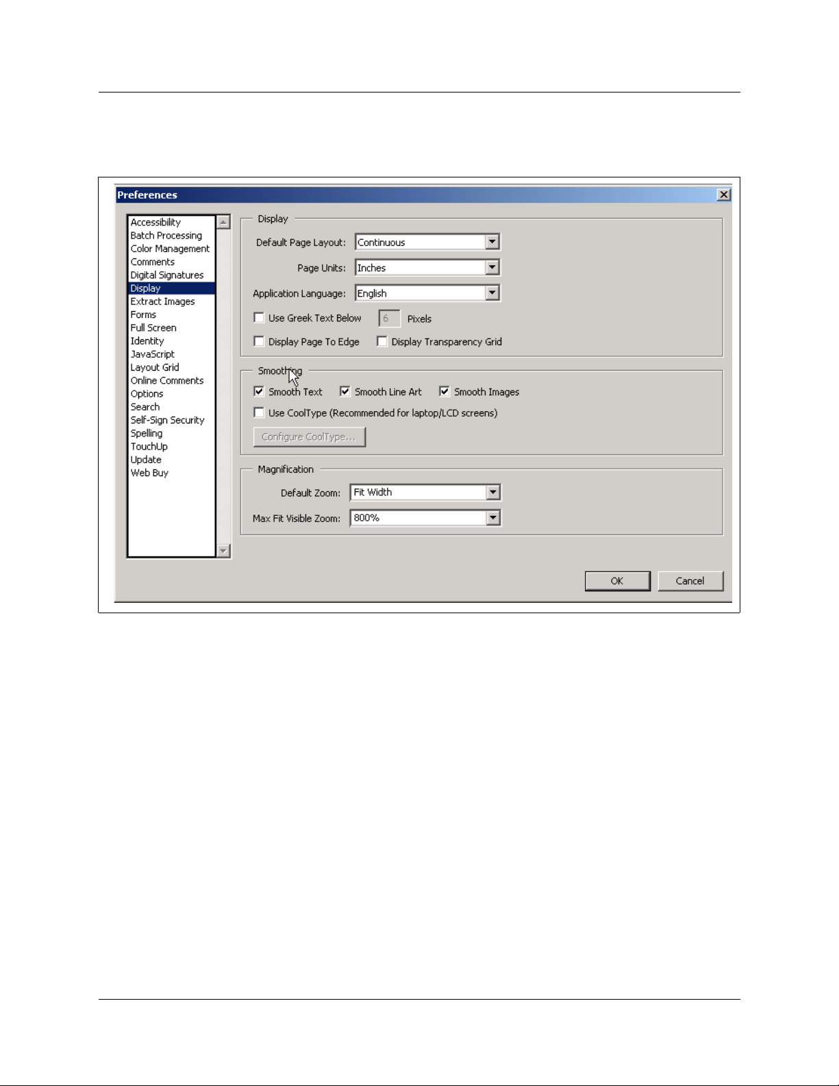
22 Preface
See Figure 1 to review Acrobat Reader version 5.0 display selections.
Figure 1 Acrobat Reader display setup selections
Text conventions
This guide uses these text conventions:
bold Courier text
italic text Indicates file and directory names, new terms, book titles, Web
bold t ext Indicates command names, s creen titl es, op tions and te xt for a graphic al
angle brackets (< >) Indicates a keyboard key press or simultaneous key presses, i.e.
P0609330 2.0
Indicates command n ames and optio ns and te xt that you n eed to enter i n
a command- lin e interface.
Example: Use the
Example: Enter
dinfo command.
show ip {alerts|routes}.
addresses, and variables in command syntax descriptions.
user interfac e (G U I).
<ENTER> or <CTRL j>
Page 27

Acronyms used in this guide
This guide uses these acronyms:
ANSI American National Standards Institute
API Application Program Interface
ARP Address Resolution Protocol
ASM Analog station module
ATA (or ATA2) Analog Terminal Adapter
AUI Attachment Unit Interface
AWG American Wire Gauge
BERT Bit Error Rate Test
BIOS Basi c Input O u tp ut Sys t em
BKI Break-in
BLF Busy Lamp Field
BootP Bootstrap Protocol
Preface 23
BRI Basic Rate Interface
CAP Central Answering Position
CDP Coordinated Dialing Plan
CHAP Challenge-Handshake Authentication Protocol
CLID Calling Line Identification
COPS Common Open Policy Service
COS Class of Service
CSMA/CD Carrier Sense Multiple Access/Collision Detection
CSU Channel Service Unit
DASS2 Digital Access Signaling System Number 2
DECT Digital enhanced cordless telecommu nications or Digital European
cordless telephone
DHCP Dynamic Host Configuration Protocol.
DiffServ Differentiated Services
DIMM Dual In-line Memory Module
DLCI Data Link Connection Indentifier
DLCMI Data Link Control Management Interface
DN Directory Number
DNS Domain Name Service (DNS)
DPNSS Digital Pri va te N e t w or k Signalling Sys tem
DRT Delayed Ring Transfer
DTMF Dual Tone Multifrequency.
Business Communications Man ager - Management User Guide
Page 28

24 Preface
EDO Extended Data-Out
FDD Full Double Density
FQDN Fully Qualified D o m a in N ame
HDLC High-level Data Link Control
HF Handsfree
HS Hospitality services
HTTP Hypertext Transfer Protocol
I/C Intercom feature button
ICCL ISDN Call Connection Limitation
IETF Internet Engineering Task Force.
IP Internet Protocol
IPSec Internet Protocol Security
IPX Internetwork Packet Exchange
IRQ Interrupt Request
ISDN Integrated Services Digital Network
ISO International Organization for Standardization
ISP Internet Service Provider
ITU-T International Telecommunication Union-Telecommunication
Standardization Sector (formerly CCITT)
IVR Interactive Voice Response
LAN Local Area Network
LCD Liquid Crystal Display
MAC Media Access Control
MAU Media Access Unit
MCDN Meridian Client Defined Network (PRI SL-1)
MIB Management Information Base
MLPPP Multi-Link Point-to-Point Protocol
NAT Network Address Translation
NBMA Nonbroadcast Multi-Access
NCRI Network Call Redirection Information
NIC Network Interface Card
NOC Network Operations Center
OIT Optivity Integration Toolkit
OPX Off Premises E xtension
OSPF Open S horte st Path First
PAP Password A uthentic ation Procedure
PBX Private Bran ch Exchange.
P0609330 2.0
Page 29

PCI Peripheral Component Interconnect Slot
PDD Partial Double Density
PPP Point-to-Point Protocol
PPPoE Point-to-Poin t Pr o to c o l over Ethernet
PPTP Point-to-Point Tunneling Protocol
PRI Primary Rate Interface
PSTN Public Switched Telephone Network
PVC Permanent Virtual Circuit
QoS Quality of Service
QSIG Q reference poi nt signalling
RAS Remote access service
RIP Routing Information Protocol
SAPS Station Auxiliary Pow e r Supply
SDRAM Synchronous Dynamic Random Access Memory
SMDS Switched Multimegabit Data Service
Preface 25
SNMP Simple Network Management Protocol
SPID Service Profile Identifier
STP Shielded Twisted Pair
TAPI Telephony Application Program Interface
TCP/IP Transmission Control Protocol/Internet Protocol
TE Terminal Equip men t
TEI Terminal Endpoi nt Ident ifier
TOS Type of Service.
TPE Twisted Pair Ethernet
UDP User Datagram Protocol
Universal Dialing Plan
VoIP Voice over IP
VPN Virtual Private Networks
WAN Wide Area Network
WFQ Weighted Fair Queuing
Business Communications Man ager - Management User Guide
Page 30

26 Preface
How to get help
Your local distributor provides technical support for your Business Communications Manager
system or has access to that information through a Technical Service Center (TSC).
USA and Canada
Authorized Distributors - Tech nical Suppor t
Telephone:
1-800-4NORTEL (1-800-466-7835)
If you already have a PIN Code, you can enter Express Routing Code (ERC) 196#.
If you do not yet have a PIN Code, or for general questions and fir st line support, you can enter
ERC 338#.
Website:
http://www.nortelne tworks.com/support
Presales Support (CSAN)
Telephone:
1-800-4NORTEL (1-800-466-7835)
Use Express Routing Code (ERC) 1063#
EMEA (Europe, Middle East, Africa)
Technical Support
Telephone:
00800 800 89009 or 33 4 9296 1341
Fax:
33 49296 1598
email:
emeahelp@nortelnetworks.com
CALA (Caribbean & Latin America)
Technical Support
Telephone:
1-954-858-7777
email:
csrmgmt@nortelnetworks.com
P0609330 2.0
Page 31

APAC (A sia Pacific)
Technical Support
Telephone:
+61 388664627
Fax:
+61 388664644
email:
asia_support@nortelnetworks.com
Relat e d public a t io ns
These documents provide furthe r information about the Business Communications Manager,
related media bay modules, extension equipment, and system applications and software:
Busine ss Communications Manager Programming Operations
Preface 27
Guide
All optional Business Communications Manager applic ations have installation and user guides
specific to that application. Refer to the Programming Ope rations Guide and Tele phone Features
Programming Guide. These guides describe core system operational configuration and how to
program the Business Communicat ions Manager equipment.
These guides provide programming for core telephony features and user features, such a s:
• Voice telephony confi guration for digi ta l, IP, ISDN and radio-based tel ephones and equipment
over analog, digital, ISDN, a nd voice over IP (VoIP) trunks.
• How to use and program user telephony features at the telephone
• Companion Applicati on Server software that controls the interface between the Business
Communi ca tio ns Manag e r sys te m and the Co m p ani on wi rel ess sys tem (av a ilab le fo r s elect ed
regions)
• Networking DPNSS (upgrade) (requires keycode) pr ovides private voice networking for the
UK Market.
• Networking MCDN and ETSI Q.SIG Voice Networking (requires keycode) allows you to
network your Business Communicat ions Manager system, or a number of Business
Communications Manager systems to a Meridian system. This allows the network to use a
common numbering plan, as well as common voice messaging and auto attendant systems
connected t o the Meridian.
• Data setup applications and protocols to configure the Business Communications Manager
system to be part of a LAN or WAN network. Refer to the next section for specifics.
Business Communications Man ager - Management User Guide
Page 32

28 Preface
Call Detail Recording System Administration Guide
Call Detail Recording (no ke ycode required) records and reports call activity from the Business
Communications Manager. You can create reports from this information to help you manage
system usage effectively.
IP Telephony Configuration Guide
• i2001, i2002, and i2004 IP telephones and the NetVision and NetVision Data telephones
require a combination of data and telephony settings to work with the Business
Communications Manager. These telephones can make or receive calls through e ither VoIP or
PBX lines.
• Nortel Networks i2050 Software Phone turns your PC into a telephone interface which
provides standard te lephony operating features such as Voice Mail, Caller ID, and multiple
telephone lines or line appeara nces. This application requires Windows 2000, a full duple x
sound card, and a computer-telephony headset. This document describes what settings are
required to use this application with the Business Communications Manager. The i2050
Software Phone Installation Guide provides specific installation information.
• VoIP Gateway (requires keycod e) converts the voice in a call into a packet format and sends
the call using an intranet tr unk. With Business Communi cations Manager VoIP Gateway , you
can make calls over any intranet connected to the Business Communications Manager system.
P0609330 2.0
Page 33

Chapter 1
Management Overview
This section provides an introduction to the Business C ommunications Manager network-level
management concepts and techn iques contained throughout this guide.
The management overview information is divided into three categories:
• Concepts and models
• Unified Manager usage
• Management User Guide overview
The sections that describe management concepts and models are as follows:
• “Network Administrat ion Objectives” on page 29
• “Network Topology and Management Interfaces” on page 31
• “SNMP Network Management Concepts” on page 34
• “Network Management and Maintenance Applications” on page 36
• “Unified Manager Applica tion Model” on page 37
29
The sections that describe the Unifi ed Manager are as follows:
• “Using the Unified Manager Configure Application” on page 42
• “Unified Manager Maintena nce Page Overview” on page 45
The sections that describe the Management User Guide are as follows:
• “Management Guide Overview” on page 53
• “BCM Monitor overview” on page 54
• “Performance management overview” on page 55
• “Security management overview” on page 56
• “Backup and restore Overvie w” on page 56
• “Troubleshooting and diagnostics activities overview” on page 57
Network Administration Objectives
Network operations cente r (NOC) responsibilities encompa ss the operation of the entire network
domain. Network administration is a complex task that requires intimate knowledge of the
construction and workings of the network environment.
Generally, NOC personnel perform the following network administra tion activities:
• Monitor rout ers, swit ches, hubs, a nd auxil iary backup s yste ms (power sup ply, data) equipment
that comprise the enterpr ise data network.
• Monitor network traffic trends and resolve network bottleneck problems.
Business Communications Manager - Manageme nt User Guide
Page 34

30 Chapter 1 Management Overview
• Manage and allocate IP addresses and domain names, record and provide remote con nectivity
to the enterprise comput ing systems.
The descriptions and proce dures contained in this guide assist with the objectives of service
assurance:
• Monitor the network for alarms and performance threshold
• Ensure service net work integrity
• fault isolat ion, diagnosis and repair
• performance management. Network Operations Center (NOC) takes first call from the alarms
and performs initial tr oubleshooting of the problem. Monitor link status and view, provision,
edit and audit connectio ns. Log into network elements. Monitor inventor y. Monitor network
performance (performance threshold provisioning).
Network management model
The Business Communications Manager network management model defines the management
functions into layers to show the flow of management information between variou s
communicating entit ies. The following figure illustrates the various management layers.
Figure 2 Business Communications Manager network model
Business & Policy Management Layer
• Policy assessment, definition & evolution
Network Managemen t Layer
• Event & Alarm Mgmt
• Infrastructure access
• Performance & optimization
• Communications
• QoS M o n i tori ng
Element Management Tools
• Troubleshoot events & alarms
• Backup & restore
Manageable Systems & Endpoints
• User applications & capabilities
• Event / alarm generation
• System data / traffic
System & Config
Management Layer
• Multi-site configuration
• Asset inventory mgmt
•Bulk MACs
• Enable /d is a ble so f tware keys
• Configuration & administration
• User access
• Threshold settings
• Software keys
P0609330 2.0
Page 35

Chapter 1 Management Overview 31
Network Topology and Management Interfaces
The Business Communications Manager Unified Manager, Network Configuration Manager and
SNMP Network manager applications support the objective s and knowledge requirements of NOC
network administrators. These applications detect, observe and report on the state of the network
elements and the overall health of the network.
Figure 3 on page 32 shows a sample Business Communication s Manager enterprise network that
illustrates th e various c ommunica tions links to e nd devices and c ontrol cons ole s. The diagr am also
shows that the physical ente rprise network, conceptually, is segmented into domains.
• The Network Operations Cente r (NOC) domain represents the tools, equipment and activities
used to analyze and maintain the oper ation of the Business Communications Manager
network. Unified Manager and Network Configuration Manager applications provide the
software interfa ce to perf orm network control and maintenance funct ions. The controller
workstations can be locate d acr oss different enterprise sites.
• The BCM network domain represents one or more Business Communications Managers
networked through an enter prise LAN to one or more controller workstation. The Business
Communications Managers need not be co-located at the same site. The WAN represents an
adjacent net wo rk , extern al to the LAN .
• The VoIP and Wireless VoIP domains represent terminating IP devices.
Business Communications Man ager - Management User Guide
Page 36

32 Chapter 1 Management Overview
Figure 3 Business Communications Manager enterprise network model
NOC Domain
Network
Configuration
Manager (NCM)
Unified Manager
Workstation
SNMP Network
Manager
Workstation
NCM
Server
NCM
Database
BCM Network Domain
Network
Solutions
VoIP
Wireless VoIP
RS232 local interfa ce
WAN
PSTN
V.90
Modem
SNMP Network
Manager Server
Remote
Dialup
Network management physical interfaces
Business Communications Manag er offers alternatives on how to connect to, and access, the
Business Communications Manag er unit and devices in the network (see Figure 4 on page 33).
Connectivity to the network and Business Communications Manager depends on the network
configuration and telephony resources built in the system.
Physically, the Business Communications Manager network can be distributed geographically
across diffe rent sites. Th e network administra tor must be able to access each B CM in the network.
P0609330 2.0
Page 37

Chapter 1 Management Overview 33
Network administrat ion personnel have the ability to configure, observe and control the operation
and performance of the Business Communications Manager through one of the available access
portals. The following interfaces provide management access to the Business Communications
Manager (see Figure 4):
• WAN IP interface: WAN internet access (IP access through the Unified Manager interface)
The WAN interfaces use T1 (with CSU), V.35, X.21, PRI/BRI MBMs Dial on demand.
Establish a connectivity path provided from the corporate LAN network to the end-user’s
WAN network or ISP over another WAN device (e.g. router elsewhere on the enterprise
premises).
• V.90 Dial-up modem interface: (North America option only) The dial-up connection
interface i s availa ble for o ccasional use . Due to modest d ia lup speeds, and potentia ll y lar ge file
sizes, dial-up has limited use. For regular backup/restore and configuration tasks, use a higher
bandwidth connectio n for management a ccess to the Business Communications Manager.
• Local RS232 serial interfa ce (COM port): Local terminal emulation interface. The Business
Communications Manager platf orm base chassis has a serial RS232 port. The RS232 port
provides local terminal emulation connectivity to the BCM. This method is normally used
upon initial in stall. Use loc al c onnectivit y to set the sys tem’ s IP a ddress a nd other basic sys te m
and networking parameters to enable the BCM for remote access. Alternatively, the RS232
port is used to establish a loc al connection to perform local main tenance activitie s in the event
of an IP network communications failure.
• LAN IP interface: local LAN port (IP access through the Unified Manager interface). The
LAN Etherne t interface transm its at 10/ 10 0 M bps. Use IP o ver a LAN E the rn et int erf ace.
Figure 4 Business Communications Manager physical interfaces
CTM 4
1Aux 2 3 4
DSM 16+
1234 1234
StatusPower
21 3 4 5
WAN card (field upgrade) connects the Business Comm unications Manager system to the wide area network.1
V.90 Modem port (available in North America only) provides PSTN dial-up access to the BCM.
2
Local RS232 COM port provides a serial connection t o a laptop for maintenance purposes. Also supports a
3
DB9 serial connection to a UPS for power monitoring (see
4
Ethernet port connector #2 provides access to internal local ar ea network
Ethernet port connector #1 provides access to external local area network
5
UPS Installation and Configuration Guide
CTM
DSM
DECT
Unpopulated
).
Business Communications Man ager - Management User Guide
Page 38

34 Chapter 1 Management Overview
SNMP Network Management Concepts
Your Business Communications Manager network uses several hardware devices and various
software applic ations. Network management software provides the ability to exerc ise control over
the network devices.
Refer to the following descr iptions:
• “Network management communication protocols” on page 34
• “SNMP network structure” on page 34
Network management communi cation protocols
The SNMP, HTTP, Telnet, and FTP protocols are fundamental to management of a network of
Business Communications Manag ers.
• SNMP (simple network management protocol): SNMP is application-layer software that
allows you to communicate with and control de vices in your network.
• HTTP (hypertext transport protocol) : HTTP is a communicatio ns protoc ol that allows users to
establish a connect ion with a W eb server and transmit HTML pages to a client browse r. BCM
is a web-server. HTTP also allows transmission of other files required by an HTTP
application.
• Telnet: Telnet is a terminal emulation communications protocol used on the Internet and TCP/
IP-based networks. Telnet allows a networ k administrator or user to use a local workstation to
log onto a remote computer and run a program. Telnet is part of the TCP/IP protocol.
• FTP (file transfer prot ocol): FTP is a protocol used to transfer file s over a TCP/IP network
(Internet, Unix). F TP allows you to log onto the network, list directories, and copy files from
other workstati ons/servers. FTP operations are performed by t yping commands at a command
prompt or through an FTP utility running under a graphical user interface (GUI).
SNMP network stru cture
Network management objectives for the Business C ommunications Manager are based upon the
FCAPS network management model (fault, configuration, administration, performance, security).
To accomplish these object ives, the Business Communications Manager must have the ability to
provide appropria te feedback to the network administrato r.
Network administrat ors use SNMP data to manage network performance, find and solve network
problems and plan for network expansion (see Network Administration Objectives on page 29).
The Business Communications Manager network management system is composed of the
following:
P0609330 2.0
Page 39

Chapter 1 Management Overview 35
• SNMP network management stations (NMS): A cons ole (se rver/workst at ion) through whic h
the network administrator performs network management activi ties upon managed objects.
The SNMP network manager server (workstation) is a physical control device equippe d with
network management applic ation software that interfac es with the Business Communications
Manager(s) in your network.
• SNMP agents: SNMP agent software interfaces and handles interaction between the device
and the SNMP network manager workstation . SNMP agents are softwa re modules resident in
network ele me nts , in this cas e the BCM. The SNMP ag en t coll ect s, stores and retrieves MI B
(management information ba se ) data and forwards the information to the SNMP network
manager server.
• Network elements (managed devices): Ha rdware components such as co mputers, router s, a nd
terminal serve rs that are connected to networks.
• Managed objects: Hardware, configuration parameters or perfor mance statistics that dire ctly
relate to the operati on of a device. Bridges, hubs, routers, or network servers are examples of
managed devices that conta in managed objects.
• Management information base (MIB) : The MIB is t he software t hat define s the data re ported
by the device and the exte nt of contr ol. A vir tual infor mation store that contains a colle ction of
managed objects.
• Management protocol (SNMP): Used to transport management information bet ween the
agents and console. Simple network management protocol (SNMP) is the standard
management protocol . An S NMP trap is a message format used by the SNMP agent to inform
the NMS of a system event.
Figure 5 illustrate s the agent and object relationship in a network and how the system provide s
event notification to the SNMP network manager workstation. Data passes from SNMP agents
(hardware/softwa re processes that report activity in all network devices) to the SNMP Network
Manager server.
Figure 5 Managed objects and agents
Fault in
Device 1
SNMP Network Manager
Workstation/Server
Network
SNMP
Messages
SNMP
Messages
Fault
SNMP
Messages
SNMP
Agent
SNMP
Agent
SNMP
Agent
Devi ce 1
MIB
Devi ce 2
MIB
Devi ce n
MIB
Business Communications Man ager - Management User Guide
Page 40

36 Chapter 1 Management Overview
Network Management and Maintenance Applications
The tools and applic ations bund led with the BCM provide stati stics a nd noti ficati ons of the system
status and operation. Various network management applications are available and compatible for
operation with the BCM or network elements .
There are three categories of network management tools and applications available:
• BCM-specific tools and applications
• optional tools and applications
• third-party tools and applic ations
BCM-specific tools and applications
• Unified Manager (see also “Unified Manager Application Model): A web-based
configuration and maintenance application bundled with the Business Communications
Manager software. Unified Manager is the single point of access for managing all
programming for individua l BCM systems. Access to the Unified Manager is password
protected, and is secure for both enterprise customers and small to medium sized businesses.
Administrators use Unified Manager to quickly set up BCM telephony and data functions, as
well as users, mailboxes, and directory numbers.
• Network Configuration Manager (NCM): Provides centralized configuration and system
management capabilitie s for a number of Business Communications Manager in a network.
This centralized functionality is required to enabl e multi-site Business Communication s
Manager customers a nd channel partners to s ignificantly reduce the cost of ownership of their
systems.
• BCM Monitor: This standalone diagnostic application allows you to view system and IP
telephony informat ion on individual Business Communications Manager units. Open several
instances of BCM Monitor to monitor sever al remote BCM systems on a single PC
simultaneously. This tool supports real-time debugging. This tool also allows you to save and
process data at a later time to generate system utilization and traf fic reports.
Optional tool s and applications
• Optivity Network Management S ystem (ONMS): Use Op tivit y NMS to manage Nort el dat a
devices such as Baystack switc hes, BPS2000, Passport LAN switches, BayRS, and Alteon.
Integrate Unified Mana ger into the Optivity Network Management System (NMS) via the
Optivity Integra tion Toolkit (OIT). Enab le BCM discovery, launch, and alarm integration into
Optivity NMS. Business Communications Manager appears as an element in an ONMS
network discovery di agram. BCM SNMP traps are dis playe d by ONMS, and Unified Mana ger
is launched from within Optivity.
P0609330 2.0
Note: If you r equire an integrated Unified Manager /ONMS configuration, c ontact Nortel
Networks to confirm the correct interoperation of the current releases BCM 3.6 and
ONMS.
Page 41

Unified Manager Application Model
Unified Manager, a web-based navigation tool, provides access to all operations and maintenance
programming functions on the Business Communications Manager system. The Unified Manager
application allows authorized administration personnel to monitor and control BCM functions
from a single site.
Unified Manager is the single point for managing all programming for individual BCM systems.
You can access Unified Manager locally via the LAN or WAN. Remote access is available via a
V.90 modem dialup. You can also access Unified Manage r through a browser from across a WAN
or Internet connecti on.
Use the Unified Manager applica tion to configure data and voice services on the Business
Communications Manager by using the appl ication’s tabs, buttons, and right-click mouse
functions. Drop-down menus provide access to dialog boxes for data entry and per formance
tracking charts and tab les for network monitoring. The Unified Manager also allows access to
alarm and event notifica tions and diagnostic informatio n.
This section includes information about:
Chapter 1 Management Overview 37
• “Using the Unified Manager main page buttons” on pa ge 37
• “Using the Unified Manager Configure Application” on page 42
• “Logging off the Unified Manager” on page 44
Using t h e Unified Manager main page bu ttons
When you access the Unified Manager main page (see Figure 6 on page 38), several selections
provide access to operations grouped under the following functional categories:
• “Configure” on page 38
• “Wizards” on page 38
• “Install clients” on page 40
• “CallPilot” on page 41
• “Documentation” on page 41
• “BRU” on page 41
• “Maintenance” on page 42
Business Communications Man ager - Management User Guide
Page 42

38 Chapter 1 Management Overview
Figure 6 Unified Manager mai n page
Configure
Access the Unifie d Manager programming inte rface for all servic es except those contr olled by the
CallPilot and IVR services.
Wizards
When you first install your system, you must run the Quick Start Wizard to set up your system
paramete rs. Thi s wizard is describ ed in the W i zard h el p, that can be acce sse d on ce y ou ent er t he
wizards section of the Unified Manager.
Use the wizards to perform the following c onfiguration tasks: Quick Start, Add Users, Edit DN
Record Template, DN Renumber, Network Update . Refer to the Programming Operations Guide
for further det ails.
The Wizards are self-contai ne d task applications that you can use to speed up some configur ation
tasks. The access icons for the Wizar ds are located on the Setup and Management Wizards page,
which is accessed through the Wizards button on the first page of the Unified Manager. Refer to
the Programming Operations Guide for further information.
P0609330 2.0
Page 43

Chapter 1 Management Overview 39
Figure 7 Wizards icon page, accessed through the Wizards button
These are the wizards that are available from this page:
• Quick Start Wizard: initializes the system and sets up your basic system information. This
wizard is only run once, when your system is first se t up.
• Add Users Wizard: allows you to change the telephony sett ings for a set of DNs or for a
single DN. You can define the settings in this Wizard, or you can use a pre-defined template,
from a local site or from a remote site, created with the Edit DN Reco rd Template wi zard.
• Edit DN Recor d Template Wizard: allows you to select Tele phony Use r Templates and
change and define the user settings for telephones. The Telephony Templat e is sto red in a file
for use with the Add Users Wizard.
• DN Renumber Wizard: renumbers a range of DNs.
• Network Update Wizard: allows you to update your syst em data netwo rk settings any time
after the Quick Start Wizard wa s run, which sets the initial network setup.
• DECT Mobile Recording Wizard: allows you to enable/disable mobile recording for one of
the base station ports.
• DECT Configuration Wizard: allows you to easily configure a DECT module. It also turns
on one of the base station ports to allow mobile recording (handset registration).
The DECT Wizards only a ppear on the Wizards page if there is a DECT module installed and
identified to the system. These wizards are discussed in the D ECT Installation and
Maintenance Guide.
Business Communications Man ager - Management User Guide
Page 44

40 Chapter 1 Management Overview
Navigating the wizards
These are some helpful hints about how the wizards wor k, a nd how to use them.
• To open the online help, from the Progra mming Wizards screen click the Programming
Wiz ards Hel p link.
• You can move back and forth between screens in the wizards by clicking the Back and Next
buttons.
• You can revise your choices and entries on any of the wizard pages until you click the Apply
button. Once you click the Apply button, the system applies the selected configurations. The
user is presented with a confirmation box that provides the approximate timing of the process.
T o check the status of the configuration, press the Refresh button. When the process is
complete, the title of the page has the word completed as part of the title.
Install clients
After you set up th e system and it is operating, you can add the keycodes for any optional features
you want to include.
Access optional applications, including those which require keycode s, through the Install Clients
button. For information about how to set up these optional features, refer to the documentation for
each application.
The install clients utility allows you to select a nd download client applications that allows you to
run multi-media software and other telecommunications functions. Applications may depend on
other components or software keys to be functional. Each application page identifies the
dependencies required in order to activate the appropriate functionality
• Select the Insta ll Clients button to download client applic ations such as
—Call Centre
—Call Pilot
—IVR
— Desktop assistant, i2050 software phone, Personal Call Manager, NetVision Symbol
phone administrator.
• Select the Insta ll Clients button to download client tool kits such as:
— CDR Client wrapper
— LAN CTE client
— TAPI 2.1 installation
— Unified Manager Java class library
• Select the Insta ll Clients button to download developer infor mation such as:
— Program description
— Develop er ca te gor ie s
— Developer partners
.
P0609330 2.0
Page 45

Chapter 1 Management Overview 41
• Select the Insta ll Clients button to download administra tive tools such as:
— Desktop assistant Pro E
— BCM Monitor
—SSH client
CallPilot
Access the CallPilot management application. CallPilot Manager is a web-based application that
you use to set up and administer CallPil ot fea t ur es such as:
• Voice ma il
• Call answeri ng
• Auto attendant
• Custom call routing
• Fax answer ing
Note: Basic CallPilot functions are standard on the Business C ommunications Manager
and you define your region and basic settings when you run the Quick Start Wizard. Refer
to the Programming Operations Guide for further information.
Documentation
Use the Documentation button to find the information you require to help you understand a nd
configure your system to your spec ifications. The entire Business Communications Manager
documentation suit e, plus a number of training panels, are included on your Business
Communications Manager computer , a s well as on the CD that accompanied your system.
• Provides access to the following documentation categories:
— Documentation on how to install hardwa re, configure and operate various BCM-specific
applications.
— Product overview
— Download Adobe Acrobat Reader
BRU
Use the BRU (Backup and Restore Utility) button to ensure the integrity of your system data. The
utility provides a way to back up your system data and configurations in the way that is most
useful for your purposes. Backed up data can be restored to the BCM if a system failure occurs,
such as a prolonged power outage. See Chapter 9, “System Backup and Restore for further
information.
Business Communications Man ager - Management User Guide
Page 46

42 Chapter 1 Management Overview
Maintenance
The Maintenance button accesses a number of maintenance tools that allow you to determi ne the
current status of the various aspects of your Business Communications M anager system. For
further information refer to the description Unified Manager Maintenance Page Overview on page
45.
Using the Unified Manager Configure Application
Unified Manager provides a web-based navigation tool that allows you to view and change
configuration s for the Business Communications Manager system.
Most changes made with Unified Manager become part of current Business Communications
Manager programming when you select an ite m from the menu option s. Howe ver, some changes
take effect after you exi t the scr een. If a programming error occurs, you must re-enter the orig inal
programming.
For further informat ion on how to use the Unified Manager interface, refer to the Programming
Operations Guide.
Understanding the nav igation tree headings
The Unified Manager naviga tion tree conta ins five main he adings tha t allo w you to access spe cifi c
areas of the Business Communications Manager system. These headings are described in the
following table.
(<IP address>)
P0609330 2.0
Page 47

Chapter 1 Management Overview 43
Table 2 Navigation tree menu functions
Heading Programming
System Provides access to Licensing, Identification and Security subheadings. This includes
a form to enter keycodes, and a list of current supported services.
The Security heading provides screens that allow you to determine the level of security
within and entering the system. Refer to Chapter 8, “Security Management.
When you select the System heading, you can view system information such as your
system name and a description about which resources and services are available.
Selecting the System heading also enables the following menu op ti ons: Configuration,
Performance, Fault, Logoff, View, and Help. These menu options provide access for
you to:
• enable/di sable services
• access CPU and memory status
• access to the alarm banner, which displays totals of alarms
• access or refresh a system inventory list
• perform system reboot or shutdown oper ations
Resources Provides access for conf iguring data and telephony resources for Business
Communications Manager hardware setup. Ref er to the
as well as in the
Services Provides access for configuring telephony and data networking services and various
other related services. Telephony information is discussed in the
Configuration Guide
Operations Guide
documentation , and t he documents for CDR Recording, LAN CTE, IVR, Doorphone,
Network adm ini stration,
and Configuration Guide
“Manually act ivating Telnet” on page 391 .
Management Provides access to the User Manager, which you use to manage the users who have
access to t he Unified Manager (Chapter 8, “Security Management), and to the Alarm
Manager, which is used to def ine why types of alarms get reported by the system. For
further infor m ati on on alarms and SNMP traps, refer to Chapter 2, “Fault Management
System.
Diagnostics Provides access to items that allow you to generate and access statistics on different
system components. Business Communications Manager provides statistics, metrics
and event logs on resources and services to help you carry out system maintenance
activities.
System metrics information is contained in the programming section to whi ch they apply .
Refer to the
Split DS30 configuration and double density configurati on are l ocated under the
Configuration menu of the MSC heading. These syst em features are discussed in the
Programming Operations Guide
DECT Installati on and M aintenance Guide
. System data configuration is discuss ed in the
. This section also supports the informati on found in the CallPilot
UPS Installation and Maintenance Guide
. To manually enable or disable the Telnet service, refer to
Programming Operations Guide
.
and the
Programming O perations Guide
.
IP Telephony
Programming
, and
DECT Installati on
IP Telephony Guide
.
Business Communications Man ager - Management User Guide
Page 48

44 Chapter 1 Management Overview
Logging off the Unified Manager
When you have f inished a session on the Unified Manage r, you need to log off correctly to protect
the integrity of the info rmation you entered.
1 Choose BCM (<IP address>) at the top of the navigation tree.
The Logoff menu is enabled.
2 Click Logoff, then se lect Logoff.
A message appears that asks you to confirm your request to log off.
3 Click Yes to continue.
4 A second message appears reminding you to cl ose your br owser window after the system has
logged out. Click Yes to continue.
A Logoff progr ess bar appears. When it the logoff is complete, the browser display will revert
to the Login screen.
5 Click the Windows exit icon (top, right corner).
6 Click the Windows e xit ic on on t he browser win dow disp laying t he Busi ness Communi cations
Manager main menu.
Note: Exit both Unified Manager browser windows, even if you want to re-log on to the
Configuration area . Onc e you have exite d both windows, you can reestablish a
connection with the Business Communications Manager and log on as usual.
Failure to log out of both browser windows could re sult in a failed attempt to re-enter the
Unified Manager Configuration section.
P0609330 2.0
Page 49

Chapter 1 Management Overview 45
Unified Manager Maintenance Page Overview
The maintenance page is a dedicated maintenance area that provides access to several maintenance
tools and capabilit ies. Gathering these tools into one location provides the network administrator
with a single source for maintenance information, helping to reduce errors and contribute to
gaining overall ser viceability efficienc y.
Figure 8 summarizes the links through the maintenance page. Select any of the links in Figure 8 to
display a description of the maintenance function.
Figure 8 Unified Manager mai ntenanc e page pat hs
Maintenance page access
Support
Contact
Alarms and traps
Maintenance
System in fo rmation
Order and enable optional components
Install optional components
Maintenance tool s
Technical support contact screen
Alarms and traps screen
Shared drive tools
Attach to a shared volume
Detach a shared volume
Enable/Disable BCM driv e shares
System interact ion tools
Execute a command
Telnet session
Troubleshooting tools
IP network troubleshooting
Services & driver troubleshooting
DECT tools
Security
Miscellaneous
System information screen
Keycode retrieval screen
Install optional components screen
DECT tools
Uploading a certificate and a private security key
Reset UM server
Archlogs
Report-a-problem
wizard
Archlog scheduler Archlog schedule screen (page 1)
Arch log vi ewer
Archlog settings
Browse logs folder
Report-a-problem input screen
Basic applica ti on selection screen
Advanced application selection screen
Archlog viewer screen
Archlog configuration screen
Archlog browse logs folder screen
Business Communications Man ager - Management User Guide
Page 50

46 Chapter 1 Management Overview
Maintenance page access
Access the maintenance page by selecting the Maintenance button on the Unified Manage r main
page (see F igure 6 on page 38).
The following table lists the tools and applic a tions available under the Unified Manager
main t e n ance page.
Support Maintenance Archlog
• Contacts • System information • Report a problem wizard
• Alarms and traps • Order & enable optional components • Archlog scheduler
• Install opti onal components • Archlog vie w er
• Maintenance tools • Archlog settings
Figure 9 shows the maintenance page selections.
Figure 9 Unified Manager Mai ntenanc e page
• Browse logs folder
P0609330 2.0
Page 51

Support
Maintenance page support selections are as follows:
• Contact
• Alarms and Tr aps
Contact
The contact screen displ ays the ITAS contact telephone numbers and contact instructions for all
regions. To display contact information, select Contact unde r the maintenance page support
category. The contact screen appears (see Figure 10) .
Figure 10 Technical support contact screen
Chapter 1 Management Overview 47
Alarms and traps
The alarms and traps screen provid es a summary list of all BCM component ID alarms. To display
alarms and traps information, select Alarms and Traps under the maintenance page support
category (see Figure 11).
Select one of the component ID alarm links to navigate to a full description of the alarm and
associated servi ce (if any). For further information on alarm s and traps, refer to Chapter 2, “Fault
Management System.
Business Communications Man ager - Management User Guide
Page 52

48 Chapter 1 Management Overview
Figure 11 Alarms and t raps screen
Maintenance
Maintena nce s e l ect io ns are as follo ws:
• System informati on
• Order & enable optional components
• Install optional components
• Maintena nce too l s
System inf ormat ion
The system info rmation scr een displays a summary o f the software r ele ase and hardwar e inventor y
currently installed on your BCM system.
To display the system information, select System information under the maintenance page
maintena nce cat eg ory . The s ystem info rm at i on screen appears (s ee Figure 12).
P0609330 2.0
Page 53

Figure 12 System information screen
Chapter 1 Management Overview 49
Order and enable optional components
The keycode retrieval search screen displays a search form that allows you to perform the
following:
• select the login loc ation in which to access the keycode retrieval system
• select the product f amily for the keycodes you need to access
• search for keywords
To display the keycode retri eval se arch screen, select Order and enable optional
components under the maintenance categor y. The keycode retrieval search scre en appe ars (see
Figure 13).
Business Communications Man ager - Management User Guide
Page 54

50 Chapter 1 Management Overview
Figure 13 Keycode retrieval screen
Install optional components
The install optional co mponents screen display allows you to perform the fol lowing:
• install the IPX rout ing protocol and services on the BCM
• install PPPoE to enable Point-to-Point over Ethernet capability on the BCM (requires a
keycode for install ation). The PPPoE product is only available for BCMs that contain 2 LAN
adapters
When you select either of the above options, the system displays an installation wizard to guide
you through the installation process.
To display the install optional components screen, select Install optional components under
the maintenance category. The install optional comp onents screen app ears (see Figure 14).
P0609330 2.0
Page 55

Figure 14 Install optional components screen
Chapter 1 Management Overview 51
Maintenance tools
The maintenance tools screen display allows you to select the tools necessary for the following
application categories:
Application Tools
Shared drive • Attach to a shared volume
• Detach a shared vol um e
• Enable/Disable BCM Drive Shares
System interac ti on • Execute a command
• Schedule a command to execute
• Schedule a restart
• Telnet session
Troubleshooting • IP network troubleshooting
• Services and driver trou bleshooting
DECT
(for further information ref er
DECT Installati on and
to the
Maintenance Guide
Security Upload certifica te and private key
Miscellaneous Reset Unified M anager server
• Time synchronizat ion
• Backup firmware
• Res to r e fi r m w ar e
)
• Firmware upload
• Restore default configuration
• A-law/Mu-law companding scheme
Business Communications Man ager - Management User Guide
Page 56

52 Chapter 1 Management Overview
When you select a tool for any o f the above ap plica tions, t he syste m displ ays an instal lation wizard
to guide you through the install ation process.
To display the maintenance too ls scre en, select Maintenance tools under the maintenance
category. The maintenan ce tool s screen ap pear s (see Figure 15).
Figure 15 Maintenance page m aintenance to ols screen
P0609330 2.0
Page 57

Management Guide Overview
This section summarizes the conte nt of the Management Guide as follows:
• “Fault management overvie w” on page 53
• “Service management overv iew” on page 53
• “Log management overview” on page 54
• “BCM Monitor overview” on page 54
• “Performance management overview” on page 55
• “Security management overview” on page 56
• “Backup and restore Overvie w” on page 56
• “Troubleshooting and diagnostics activities overview” on page 57
Fault management overview
This section provides a description of the alarm management system, system events and S NMP
traps. Administrators access alarms and perform fault analysis through the Unified Manager
interface. Use the Unified Manager to configure the fault system. This section provides detailed
information on
Chapter 1 Management Overview 53
To further informati on on how to manage system faults, refer to Chapter 2, “Fault Management
System,” on page 59.
This section also provides a correlation between the event source (SNMP traps), components, logs
and services . For fu rth er d etai ls, refer to the fo llow i ng:
• “Component ID (alarm) summary information” on page 92
• “Component ID/SNMP Trap Error Interpretation” on page 100
Service management overview
This chapter describes service manager capabilities available in the Unified Manager interface.
This chapter also describes the properties of the services in the service manager and associated
alarm notifications.
To further information on services, refer to Chapter 3, “Service Management System,” on page
245.
Use the Service Manager to access, ass ess or modify the state of services running on the Busin ess
Communications Managers in your network. Servic es control the fundamenta l functional ity of the
Business Communications Mana ger. A service is a software process that controls interaction with
the Business Communication s Manager hardware devices, computing environment, telephony or
your browser interface .
Business Communications Man ager - Management User Guide
Page 58

54 Chapter 1 Management Overview
Modification of any servi ce has far reaching effects on communications or event r eporting
capability. Nortel Networks strongly recommends you consult with your support group prior to
using the service manager inte rface.
There are two categories of services:
• System level services: Software processes that are critical to essential operating system level
features (see “System-Level Service Definiti ons” on page 252)
• Nortel Networks conf igurable se rvic es: Software processes that are critical to the operation of
the Business Communications Manager software (see “Nortel Networks Configurable
Services” on page 278)
Log management overview
This section describe s the Media Service Card (core telephony) logs. All compone nts of the
Business Communications Manager are logged and hence, the system generates a la rge number of
logs for a variety of purposes. In the case of faults, consult the logs to assist in the diagnosis and
correction of the problem.
Some of the logs run continuously and collect information to help you troubleshoot in the event of
system problems. The network administrator is able to disable some logs because the information
collected may not be of immediate or critical interest to maintain the heal th of the system.
The system generates the foll owing MSC logs:
• MSC System Test Log: Contains diagnostic test results, tele phony events and alarms, audits.
It has a maximum size of 20 items, after which events are aged out to make room for new
events.
• MSC System Administration Log: Contains log-in, log-out information. Has a maximum of
10 entries. The 11th entry overwrites the 1st entry regardless of severity level.
• MSC Network Event log: Contains T1 / PRI network interface events and alarms. This log
has a maximum size of 10 events.
For further information on Business Communications Manager logs, refer to Chapter 4, “Log
Management System,” on page 309.
BCM Monitor overview
Business Communications Manag er diagnostics involves both monitor ing system status and
assessing performance.
To download and use the BCM Monitor application refer to Chapter 5, “BCM Monitor,” on page
329.
P0609330 2.0
Page 59

Chapter 1 Management Overview 55
BCM Monitor is an optional, standalone application that allows the syste m administrator to view
system and IP telephony information for each Business Communications Manager. Open several
instances of the applica tion on a single PC to monitor the corresponding number of Business
Communications Manager syst ems.
BCM Monitor supports real time troubl eshooting and report generatio n. Sys tem administrators
and support personnel obtain key, real-time information to perform troubleshooting if necessary.
The system administrator accesses and saves information to generate system utilization and traffic
reports.
Using BCM Monitor to monitor your system status
The Business Communications Manager (BCM) monitor allows you to see the curr ent status of
various parts of your system ser vices.
Use the BCM Monitor tool during troublesho oting to confirm current configurations, including
CallPilot applications and IP trunk information. You can find BCM Monitor under the Install
Clients button on the first page of the Unified Manager. The section that describes BCM Monitor
provides the following main topics:
• “Starting BCM Monitor” on page 329
• “Use BCM Monitor to Analyze your System Statu s” on page 331
• “BCM Monitor Statistical (minimum and maximum) Values” on page 340
• “BCM Monitor information capture ” on page 341
Performance management overview
The Unified Manager System Performance m onitor pr ovides detaile d perfor mance inf ormation f or
the system and the system resources. The statis tics are shown in charts o r table format. If a
performance display is active, it is automatically update d with r eal-time performance informat ion
in time increments that you set.
BCM performance and usage informati on can be queri ed by SNMP.
For further details on performance management, refer to Chapter 6, “Performanc e Management, ”
on page 345.
Use the following tools a nd procedures to monitor the Business Communications Manager system
performance:
• “Unified Manager Performance Monitor
• “Service M anag er
• “Base function tray system status display LEDs
• “Using the Initialization menu to monitor system hardware
• “Disk mirroring function
• “Module Diagnostics
Business Communications Man ager - Management User Guide
Page 60

56 Chapter 1 Management Overview
If you determine through the use of the diagnostic tools, that a hardware problem exists, refer to
the Installation and Maintenance Guide for information on component replace ment.
Security management overview
When you first r un the BCM version 3.6 software, you will note that the default Web acc ess to the
Business Communications Manag er now utilizes SSL encryption for system security. This
includes the appearan ce of a secur ity alert when you initiate a connection to the Unified Mana ger
using SSL, which indicates site validation of the default certificate.
For further information on how to define security parameters for the system and for users, refer to
Chapter 8, “Security Management,” on page 377.
Security management include s the following primary topics:
• “Understanding BCM SSL certific ate properties” on page 377
• “Security Management Tools” on page 379
• “Setting the Interf ace Timeout” on page 380
• “Setting system security compatibility levels” on page 380
• “Managing access password s” on page 382
• “Using the SSH client to access the text-based interface” on page 390
• “Manually activating Telnet” on page 391
• “Access Unified Manager thr ough the Firewall” on page 392
Backup an d r esto re O verview
The backup and restore utility (BRU) provides a means to preserve the integrity of your Business
Communications Manager operating system software and configuration data. The BRU
application al lows you to perform a backup, restore or upgrade via a web connection. The BRU is
a single-user application.
Before you perform any substantial maintenance on the Business Communicati ons Manager, save
your data to a safe storage module location elsewhere in the network. After hardware maintenance
is complete, r estore the data to your Business Communications Manager.
For further information on how to operate the Backup and Restore utility, refer to Chapter 9,
“System Backup and Restore,” on page 395.
Backup and restore procedures are as follows:
• “Accessing the backup and restore utility” on page 411
• “Exiting from the backup and r estore utility” on page 411
• “Resetting the BRU screen” on page 412
• “Adding a new volume” on page 412
• “Modifying a volume” on page 413
P0609330 2.0
Page 61

Chapter 1 Management Overview 57
• “Deleting a volume” on page 413
• “Performing a backup using the BRU” on page 414
• “Scheduling a backup” on page 417
• “Viewing scheduled backups” on page 419
• “Viewing a scheduled backup report” on page 419
• “Deleting a scheduled backup” on page 419
• “Performing a restore using the BRU” on page 420
Troubleshooting and diagnostics activi ties overview
This section contains information about diagnosing module line performance issues and device
line issues. This section also provides instructi ons on how to perform a system startup, set
identification parameters and m aintain telephony resources.
For further informat ion on diagnostics activities , ref er to Chapter 10, “Testing, Troubleshooting,
and Diagnostics,” on page 423.
This chapter contains the following information:
• “Module Diagnostics” on page 423
• “Problems with trunk or stati on modules” on page 426
• “Media Bay Module status” on page 427
• “Testing DTM Modules” on page 429
• “DTM CSU statistics” on page 431
• “Testing the DDI Mux” on page 434
• “Troubleshooting Telephone Connections” on page 439
• “Performing a system start up and warm rese t” on page 441
• “Changing system identification parameters” on page 442
• “Maintenance progra mming for telephony resources” on page 444
• “General Diagnosti c Activities” on page 457
• “Emergency tele phone does not function” on page 464
• “ATA 2 does not function” on page 464
• “Unified Manager Diagnostics” on page 466
• “Driver Debug diagnosti cs” on page 466
Business Communications Man ager - Management User Guide
Page 62

58 Chapter 1 Management Overview
P0609330 2.0
Page 63

Chapter 2
Fault Management System
Business Communications Manag er fault management includes the following major topic s
• “BCM Fault Management T ools” on page 59
• “Alarm Management System” on page 60
• “Alarm Reporting System” on page 61
• “Access and Configure the Alarm Syst em” on page 65
• “SNMP Traps” on page 74
• “Configuring an SNMP Community” on page 76
• “Configuring an SNMP Manager List” on page 80
• “Configuring an SNMP T rap Community List” on page 84
• “Alarm Analysis and Clearin g Procedures” on page 89
• “Component ID (alarm) summary information” on page 92
• “Component ID/SNMP Trap Error Interpretation” on page 100
• “Component ID alarm descriptions” on page 101
• “Events that cause a system restart” on page 242
59
BCM Fault Management Tools
Fault management activi ties range from system setup, monitoring and repor ting to fault
identificat ion, diagnosis and correction. The toolsets available to the BCM network administra tor
to access alarms and perform fault analysis are as follows:
• Alarm management using the Unified Manager Interface
• SNMP traps for remote fault management
Administrators access alarms and perform fault analysis thr ough the Unified Manager interface.
Business Communications Manager - Manageme nt User Guide
Page 64

60 Chapter 2 Fault Management System
Alarm Management System
The Business Communi cations Manager tracks and generates appr oximately 700 different alarms.
For example, alarms can provide notification that a network interface is not behaving as expected,
or that certain anomalie s in syste m operation have been detected.
When the Alarm Man a ge me n t system is enabled, al l BCM alar ms are rec o rded int o the N T Event
Log. Use the Alarm Banner of the Unified Manager to view alarms for each Business
Communications Manager. A subset of the alarm information pertaining to BCM core telephony
may also appear at the Alarm telephone, and in the MSC logs. Managing alarms within Unified
Manager is described on pages
Note: Assign the Alarm telephone in Feature se ttings under System programming.
Alarms have a higher severity tha n events. Attend to alarm codes before event messages
Alarm code information that is specific to Companion components is included in the
Windows NT Event Log.
Any information sent to the Windows NT event log c an generate an SNMP trap.
“Alarm Analysis and Clearing Procedur es” on page 89.
All BCM alarms can also be sent to a remote management system through an SNMP trap. For
information on how to perform remote fault management of BCM SNMP traps, refer to
Configuring an SNMP Community on page 76.
An alarm may not appear unti l two minutes after it is triggered. If the system is powered off when
the alarm is triggered, the al arm does not appear until two minutes after the system is power ed on.
For further inf ormation about BCM alarms, see ““Alarm Analysis and Clearing Procedures” on
page 89. For an explanation of BCM SNMP traps, see SNMP Trap s on page 74. For information
about the MSC logs, refer to Media service card (cor e telephony) logs on page 309.
P0609330 2.0
Page 65

Chapter 2 Fault Management System 61
Alarm Reporting System
Figure 16 on page 61 illustrates the internal processes by which the Business Communica tions
Manager manages system events.
Figure 16 Business Communications Manager events and alarms
Operating system, drivers
& applications
MSC
1
Telephony
Services
2
4
1
5
NT Event Log
Database
Alarm Manager
User defined
alarm filters
6
Alarm filters
SNMP Trap
Management
10
9
7
Alarm
database
NT SNMP
Extensible
Agent
SNMP
Traps
Alarm Banner
8
3
MSC Log
Database
Core telephony services running on the Media Serv ices Card (MSC), generate event outputs (see
1
“Event sources).
The system forwar ds all BCM core teleph ony (MSC) ev ents, i nclud ing ala rms, to the MSC telepho ny eve nt
2
logs.
BCM telephony (MSC) event logs include t he MSC System Test Log, MSC System Admin Log, and
3
MSC Network Event log. These logs capture all of the MSC (core telephony) system events (including
MSC alarms)
All BCM core telephony (MSC) alarms are written into the NT Event log database. A subset of the
4
core telephony (MSC) events are also written into the NT Event log dat abase.
The NT Event Log database captur es events from all BCM components, including MSC alarm and
5
some MSC event information.
6
The Alarm Manager applies system filters based on configuration inputs.
The Alarm database captu res all NT event information after system filt eri ng is applied.
7
Alarm Banner / Alarm Browser pro vides real-time displ ay of alarms within Unified Mana ger.
8
The Alarm Manager SNM P subsystem applies filters to the BCM alarms based on user inputs about
9
severity level s and event sources.
BCM alarms meeting the SNMP trap crit eria are forwarded to the SNMP trap r eporting interface in
10
accordance with the trap community list
Alarm Browser
Business Communications Man ager - Management User Guide
Page 66

62 Chapter 2 Fault Management System
Event sources
All BCM components can be a source of BCM event information. An event is defined as a
notification of an error or anomaly in operation, or a condition that may lead to an error or
anomaly. The terms “event” and “alarm” are use d interchangeably in the BCM environment.
Refer to Figure 16 when reviewing the following description:
• BCM events derived from the operating system , dr ivers, services and applications, are
captured in the NT Event Log (item 5).
• The BCM events are recorded in the BCM Alarm database (item 7) and displayed as alarms in
the Alarm Banner (item 8). See also Figure 18.
• The BCM events, or alarms, can also be made available to remote fault management systems
as SNMP traps (item 10).
MSC event s
Core telephony services, which run on the Media Services Card (MSC) (item 1 of Figure 16)
represent one of the maj o r BC M com po ne nts that act as a source of even ts. Refe rre d to as MS C
events or core telephony events, these events are assigned an MSC event id and an event priority
from P1 to P9, where P9 is the most severe. If an MSC event is serious enough to be considered an
alarm, the syst em al so assig n s the MSC event an MSC al arm id.
Refer to Figure 16 when reviewing the following description:
• All core telephony (MSC) events, including telephony alarms, are recorded in a set of core
system telephony logs (ite ms 2 & 3).
• All core telephony (MSC) events designated a s alarms are also written into the NT Event log
(item 4). In most cases, the MSC alarm id, assigned by the core telephony (MSC) service, is
re-used as the NT Eve nt ID.
• Some of the core telephony (MSC) events, which are not alarms, are also written into the NT
Event log, primarily those MSC events of priority P5 and higher (item 4). MSC events of
priority P4 and lower can only be seen in the MSC logs - see “MSC (core telephony) logs” on
page 63). MSC events that are visible to the alarm service can also generate SNMP traps.
Due to the interaction between the MSC system and the BCM alarm system, an event in the NT
event database which originates from the core telephony services (MSC) will have an NT event
ID. An event will also have an associated core telephony (MSC) services event ID, and possibly
also an MSC alarm id.
MSC event and alarm conditions
• Software error s that do not affect system operatio n
• Software errors that affect system operation: feature failure dropped calls, or system resets.
P0609330 2.0
Page 67

Chapter 2 Fault Management System 63
• Events ca used by hardware- related problems, but are not of sufficient severity as to b e marked
as an alarm condition. Installers, however, may need to know of these events as they may
indicate a hardware problem (e.g. , bad messages received on a signa lling channel) or a PSTNor private network- related problem (e.g., no battery feed, no dial tone, invalid disconnect
sequence).
• Events that are not of suf ficient severity as to marked as an alarm condition, but where the
problem is related to system limits affected by system usage patte rns, administration, or lack
of resource. Examples are running out of autodialler/speed dia ler bins, LHD nodes, DTMF/
dial tone receiver s. The se events may not be apparent to users, but a degr aded le vel of service
will likely result.
• Information events, concerning a user action, typically in **ADMIN or **CONFIG. (e.g.,
admin log cleared, user attempted to enter **ADMIN with wrong password).
• Permanent, service affecting events that an installer can rectify. Typically these will also be
alarms, but tha t is not a prerequisite. An example of the latter is the defaulting of a portion of
administrati on, without a cold start (installer action: re-administer the data ).
MSC (core telephony) logs
Refer to Figure 16 when reviewing the following description:
• MSC logs (item 3) are maintained on the Media Services card, MSC, which is the telephony
side of the Business Communicati ons Manager system.
• The MSC logs are actually a set of three logs, the MSC System Test, MSC System
Administration, and MSC Network Event log. These logs capture all of the core telephony
(MSC) syst em eve nts, (i ncl ud ing alarms). For furth er inf or ma tio n, ref er to “Media service
card (core telephony) logs” on page 309.
• Note that core teleph ony (MSC) events, designated as MSC alarms, are sent to the NT Event
Log in addition to being recorded in the MSC (core tele phony) logs (item 4). Also, MSC
events of priority 5 (P5) and higher are sent to the NT Event log (item 4). MSC events are
shown in the BCM alarms under component id “Voice Software”.
NT Event log database
When the alarm service is enabled, all BCM alarms are recorded into the NT Event Log (item 5 of
Figure 16).
For further information about how to view NT Event Logs, see “Obtaining NT Event Logs from
Archlog” on page 327.
Alarm manager
Refer to Figure 16 when reviewing the following description:
• The system forwards event s from the NT Event log to the Alarm Manager.
• The Alarm Manager applies system filters based on configuration inp uts.
Business Communications Man ager - Management User Guide
Page 68

64 Chapter 2 Fault Management System
• The events are then recorded into the Business Communications Manager alar m database .
Alarm da tabase
Refer to Figure 16 when reviewing the following description:
• The alarm database (ite m 7) holds a maximum of 5000 alarm rec ords. The network
administrator configures the record capacity of the alarm database to a smaller size if required.
• Use the Unif ied Manager Alarm Manager batch archive function to archive the inf ormation in
the alarm database. Set the batch job pa rameters (day of the week and time) and file
destination. For further information on how to configure and use the alarm manager, refer to
Configuring alarm manager settings on page 69.
Alarm banner and alarm browser
The Alarm Banner and the Alarm Browser (ite m 8, Figure 16) provide real-time inf ormati on about
events occurring with in the Business Communications Manager system.
Alarm system interfaces
• The Alarm Banner window allows you to continua lly monitor the Business Communications
Manager sy stem fo r alarms. For more info rma tio n , ref er to “Accessing the alarm b an ner to
monitor alarm notification” on page 67.
• The Alarm Browser window allows you to browse through a list of alarms and provides
detailed information on each one. For more information, Refer to “Accessing the alarm
browser to analyze alarm detail” on page 68.
• Alarm Manager a llows you to manag e the col lection a nd s torage of a lar m informat ion. Use the
Alarm Manager to enable or disable sending of all or some types of SNMP traps. The Alarm
Backup Batch Job application ba cks up old alarm records to an archive folder at scheduled
time intervals. For further information on how to use the Backup Batch Job, refer to
“Configuring alarm manage r settings” on page 69.
BCM alarm se verity
Alarm severity refers to a scale in which an alarm notification is categoriz ed. The alarm severity
prescribes the degree of appropriate user interventi on.
There are four alarm severity levels: critical, major, minor, and warning.
• Critical alarms indicate system problems that require im m ediate corrective action.
• Major alarms indicate system problems that require corrective action.
• Minor alarms indicate system problems that do not affect system performance and may or
may not require action.
• Warning alarms indicate syst em status changes that normally do no need any corrective
action.
P0609330 2.0
Page 69

Chapter 2 Fault Management System 65
Access and Configure the Alarm System
The alarm service works to generate SNMP trap event notifications. You must also enable and
configure SNMP traps. The Business Communications Manager alarm service performs the
following functions:
• Monitors Windows NT event logs for incoming events.
• Synchronizes Windows NT logs with Business Communicatio ns Manager alarm database.
• Receives eve nts (alarms) from other Business C ommunications Manager applications thr ough
its API and logs the events in the Business Communica tions Manager database.
• Archives alarm hist ory based on the criteria defined in Alarm Manager.
• Monitors the alarm conf iguration changes and updates SNMP trap agent and Alarm Service.
Note: When the alarm service is enabled, the Business Communications Manager system
automatically archives the BCM Event logs. See “Enabling the alarm service” on page
66.
Note: The alarm serv ice i s disa ble d by def ault. You mu st enab le t he alarm s erv ice t o
view alarms on the alarm banner (see “Enabling the alarm service” on page 66).
Note: You must configure how the system handles SNMP trap notifications. Events
arriving in the alarm datab ase tr igger an SNMP trap message to be generated. If you do
not configure SNMP traps, you will not obtain optimum alarm reporting capability.
Business Communications Man ager - Management User Guide
Page 70

66 Chapter 2 Fault Management System
Enab ling the alarm service
Use this procedure to enable the alarm service from the Unified Manager interface and to view
alarms on the alarm banner.
1 Access the correct Business Communications Manager in your network from the Unified
Manager workstation browser.
2 Select the Services key from the Unifie d Manager main page and expand the nav igation tree.
A list of available servic es appears in the Services information frame .
3 Select the Alarm Service heading from the navigation tree window.
The Alarm Service Summary dialog box appears.
4 From the Status list box, change the status of the alarm service to Enabled.
(See Figure 17 on page 66).
Figure 17 Alarm service selection window
5 Press the Tab key to save the settings.
P0609330 2.0
Page 71

Chapter 2 Fault Management System 67
Accessing the alarm banner to monitor alarm notification
Use the alarm banner to continually monitor the Business Communications Manager syste m for
faults or alarm conditi ons. The alarm banner stays active on your desktop for quick acc ess. The
banner displays color codes to represent the alarm severity and the number of alarms for each
severity level. The alarm banner displays alarms in real time.
Note: You must enable alarm service before the alarm banner will function. To enable the
alarm server, refer to “Enabling the alarm service” on page 66.
Complete the following steps to access the alarm banner.
1 Access the correct Business Communications Manager in your network from the Unified
Manager workstation browser.
2 On the Unified Manager navigation tree select the System heading.
The Performance, Fault and Tools menus are enabled.
3 From the Fault menu select Alarm Banner.
The Alarm Banner appears (see Figure 18 on page 67).
Figure 18 Alarm bann er
4 Select any color coded alarm button to view a report of active alarms.
The Alarm Browser appears. See “Accessing the al ar m br o wse r to anal y ze alarm detail” on
page 68 for more informat ion.
Business Communications Man ager - Management User Guide
Page 72

68 Chapter 2 Fault Management System
Accessing the alarm browser to anal yze alarm detai l
With the alarm b row s er yo u can acc es s and d et ect an ala rm occu r ring o n the sys tem. W ith the
alarm browser you can display detailed information on each alarm to assist you to perfor m
corrective acti on, if neede d.
See the section “Alarm Analysis and Clearing Procedures” on page 89 for a detailed explanation
on how to navigate through the alarm clea ring process and the descriptions in thi s guide.
To access the alarm browser and alarm detail screen
1 Access the correct Business Communications Manager in your network from the Unified
Manager workstation browser.
2 On the navigation tree clic k the System heading.
The Performance, Fault and Tools menus are enabled.
3 On the Fault menu click Alarm Banner.
The Alarm Banner appear s.
4 Select any color c oded alarm button from the alar m banner to dis pla y a report of act ive alarms .
Select ALL (white button) to browse throu gh the complete list of system alarms, regar dless of
the severity level. The alarm browser screen appears.
5 Select the row correspondi ng to the alarm for which you want detailed information.
6 On the alarm page click the Actions menu and select Display Details.
The Alarm Details screen appears. The Alarm Details screen is a read-only display.
P0609330 2.0
Page 73

Figure 19 Alarm browser and detail screen
Chapter 2 Fault Management System 69
7 Close the Alarms Details screen when you are finished vie wing the alarm detail.
8 Close the Alarm Browser screen when you are finished viewing the alarms for this severity.
Configuring alarm manager settings
The Alarm Manager enables you to manage the collection and storage of alarm information. The
Alarm Manager allows you to set different collection parameters for the Alar m Database. You can
use the Alarm Manager to enable or disable the sending of all or some types of SNMP traps. The
Alarm Manager provides the Alarm Backup Batc h Job, an application which backs up old alarm
records to an arc hive fo ld er at a schedu l ed time .
To configure alarm manager settings
1 On the navigation tree, click the Management key and click Alarm Manager.
The Alarm Database, SNMP Trap and Alarm Backup Batch Job windows appear.
Business Communications Man ager - Management User Guide
Page 74

70 Chapter 2 Fault Management System
Figure 20 Alarm manager dat abas e fields
2 Use the information from the following table to configure the Alarm Database:
Table 3 Alarm Database settings
Attribute Description
Maxi mu m Num be r
Record
Kept Timer (days) Allows you t o set the number of days that the records r em ain in the database before the records
Resync Timer
(seconds)
Allows you to set the maximum number of record s that the alarm dat abase stores. The default is
0 (no limit).
The range is from 0 to 5000 records. If you enter 0, there is no limit to the number of records.
When the number of records reaches the maximum, t he earliest record is rem oved to make
room for the new alarm record.
are archived.
Allows you to set, in seconds, the interval at which the alarm service init iates a synchronization
operation with the Business Communications Manager's internal event logs. This
synchronization is in addition to the normal synchronization operations triggered by the arrivals
of new events.
P0609330 2.0
Page 75

Chapter 2 Fault Management System 71
Table 3 Alarm Database settings (Continued)
Attribute Description
Archive Location Allows you to enter the path to the director y where the archives of alarm information are kept.
The default path is: d:datafiles\nortel networks\unified manager\archive\.
Nortel Networks highly recommends that you do not change this path from it def ault value.
An archive of the al arm informa tion is made whe n an Al arm Backup Bat ch Job is run or whe n th e
Alarm Service is star ted. During an archive operation, the alarm database is copied to the
archive location and the alarm dat abase is then emptied.
During an archive operation, the Busines s Commu nications Manager's int ernal event logs are
also copied t o the archive locati on and the event logs are then emptied. The file names of these
internal eve nt l og archives are:
System Event Log SystemLog YYMMDDHHMM.evs
Application Event LogApplicationLogYYMMDDHHMM.evs
Security Event LogSecuri ty LogYYMMDDHHMM.evs
Where:
YY is the year the archive was created
MM is the month the archive was created
DD is the day the archive was created
HH is hour the archive was created
MM is the minute the archive was created
3 Press the TAB key to save your settings.
4 Click the SNMP Trap tab.
Business Communications Man ager - Management User Guide
Page 76

72 Chapter 2 Fault Management System
Figure 21 SNMP Trap screen
5 Use the information from the following table to configure the SNMP Trap:
Table 4 SNMP Trap settings
Attribute Description
Traps Enabled Allows you to enable or disable the sending of SNMP traps when a new event arrives in the alarm
Information
Events
Forwarded
Warning Events
Forwarded
Error E v en t s
Forwarded
Source
Exclusion List
database.
Allows you to enable or disable sending SNMP traps when an “Information” event arrives in the
alarm database. If you have auto SNMP trap dial out set up, and the value for 'Traps Enabled' is
'Yes', settin g "I nformation Events Forwar ded" to "Yes" causes the BCM to repeatedly redial the
trap client. Always set "Information Events Forwarded" to "No" when SNMP trap dial out is set up.
If the name of a demand dial inter face is selected as 'Int erface' (when you add/modify a trap
community entry) and the 'Traps Enabled' field value is 'Yes', Nortel Networks recommends you
specify the value of the 'Informa tion Event s Forwarde d' field as ' No'. If you speci fy a value of “Yes”,
the BCM will constantly redial to the trap client.
Note: Windows 95/98 is not supported on a receiving system for the 'SNMP trap dialout' feature.
Allows you to enable or disable sending SNMP traps when a “Warning” event arrives in the alarm
database.
Allows you to enable or disable sending SNMP traps when an “Error” event arrives in the alarm
database.
Allows you to add, in a comma-separated format, a list of event sources from which SNMP traps
must not be generated. The source exclusion list prevents you from recei ving SNMP traps which
have no meaning to you.
P0609330 2.0
Page 77

6 Press the TAB key to save your settings.
7 Click the Alarm Back up Ba t ch J ob tab.
Figure 22 Alarm backup batch job screen
Chapter 2 Fault Management System 73
8 Use the information from the following table to configure the Alarm Backup Batch Job:
Table 5 Alarm Backup Batch Job se ttings
Attribute Description
Batch Job Allows you to start or stop a schedu led batc h backu p to an archive f older. The Alarm Back up Batch
Job uses the Kept Timer value fr om the Ala rm Database screen to determine when to archive an
alarm record.
Schedule Day Allows you to set the day when the system must perform the backup.
Schedule Time Allows you to set the time the backup must start.
Tips
Before you change the day or time, or both, you must first stop the batch job, make yo ur changes,
and then start the bat ch job again.
9 Press the TAB key to save your settings.
Business Communications Man ager - Management User Guide
Page 78

74 Chapter 2 Fault Management System
SNMP Traps
A trap is a signal that tells a program that an event occurred in the system. When a program
receives a signal, a specif ic set of activities take place.
The SNMP system enables SNMPv1 traps to be generated based on all or a subset of NT Events
generated on the Busine ss Communicati ons Manager. Any informat ion sent to the BCM Windows
NT event log and shown in the Alarm Banner and Alarm Browser can generate an SNMP trap.
SNMP traps received from Business Communications Mana ger contain descript ions of the alarms
that occur in the system. Additionally, SNMP generic traps such as c oldStart, linkDown, linkup,
authenticati onFailure, are als o generated from the Business Communications Manager, depending
on the user’s configurat ion.
For the BCM to generate SNMP traps, you must configure how the system handl es SNMP trap
notifications. When SNMP is enabled, events arriving in the alarm database trigger a n SNMP trap
message to be generated. Use the alarm manager to enable or disable sending of all or some types
of SNMP traps.
The trap format is specified in the BCM “Small Site Ev ent MIBs” on page 472 and is captured and
viewed through any standard SNMP fault monitoring framework or trap watcher (see “Appendix
A Management Informat io n Ba se (MIB) System ).
BCM alarm and SNMP trap list
The complete set of BCM Alarms and SNMP traps is provided (see “Componen t ID (alarm )
summary information” on page 92). You can also view the BCM Alarms list using the following
methods:
1 Access the Uni fied Ma na g er Ma int enance page. Se lect the he adi n g “Alarms and Traps” . The
Alarms and Traps selection presents a list of the events (see Table 12 on page 92).The events
are organized by event source.
2 Contact your Business Communications Manager Nortel Networks Systems Engine er,
Services organization, or PLM and request a list in Excel spreadsheet format.
Alarm banner, NT event databa se, and SNMP trap correlation
Although the same events (alarms) are reported in the Unified Manager Ala rm System, made
available remotel y via SNMP traps and recor ded in the NT Event logs, the terminology used to
denote severity levels is not the same.
P0609330 2.0
Page 79

Chapter 2 Fault Management System 75
Refer to the table Alarm banner, NT Event and SNMP trap severities or types to interpret the
severity for each type of notification The terminology used to denote sev erity levels between the
NT Event log and in the Alarm Banner is not identical.
Table 6 Alarm banner, NT Event and SNMP trap severities or types
Alarm priority Al arm Banner NT Event SNMP Trap Type
High critical Error Error
Medium major or minor Warning Warning
Low warning Information Information
Refer to the table SNMP trap types to interpret the severity for each type of notification. The
mapping between alarm severity levels and SNMP trap types (or 'specific-t rap' code) is
summarized in the table.
Table 7 SNMP trap types
Alarm Severity SNMP Trap Type (specific-trap code)
critical eventError (3)
major eventWarning (2)
minor eventWarning (2)
warning eventInfo (1)
The BCM Alarm system denotes the source of a BCM alarm as “Component id”, whereas the
SNMP system de n ote s the sou rce of the sam e information as a trap of sour ce “ev e ntS our ce”. The
terminology used in this document of Component ID (alarm )/ eventSource (trap) is intended to
show that these two systems call the same information by a different name.
SNMP trap filtering
Trap filtering is supported at the Business Communications M anager by using a source exclusion
list and severity level (Error, Warning, Info). In this way, traps of type “error” (or severity level
critical) a re forwarde d in acc ordance with t he trap communi ty li st. The trap fil ters limit t he volume
and type of SNMP information and allows the Network Administrator to control essential
information trans ferred on the network.
Use the fields on the SNMP Trap tab in the Alar m Manager to set the fi lter s for SN M P t raps
(BCM-->Management-->Alarm Manager-->SNMP Trap).
SNMP guidelines
The SNMP service i n Business Communications Manager responds to r equests from manageme nt
stations, generates SNMP traps corresponding to events and reports to trap subscriber stations.
Business Communications Man ager - Management User Guide
Page 80

76 Chapter 2 Fault Management System
Use the following SNMP guidelines:
• Set read-only and read-write community names.
• Set a list of permitted manag ers. When set, the agent responds to SNMP managers requests
from those IP hosts only.
• An empty list of permitted manage rs implies that the agent responds to requests from anyone.
• Set trap communities. Each trap entry identifies the community name that must be used and
the manager addresses.
• Enable or disable sending authentication traps.
• Enable or disable the SNMP agent.
About defining SN MP trap destinations
Use the following to define SNMP trap desti nat ions:
• A community list specifying community name and access privileges
• a manager list spec ifying S NMP manager IP addres ses, i n oth er words SNMP mana gers which
are allowed to make SNMP queries to the Business Communica tions Manager
• a trap community list which specifies de stinations to which SNMP traps should be sent if
SNMP traps are enab l ed
Although no specific limit is se t for the number of trap communities, Nortel Networks
recommends that you limit the number of trap communities to a maximum of 5. Limiting the
number of trap communities ensur es that system performance does not degrade.
Configuring an SNMP Community
Use the procedures in this section to configure the Business Communications Manager to send
SNMP message s to an S NMP works tation.
• Configuring SNMP summary attribu tes on page 76
• Adding a community to an SNMP community list on page 78
• Modifying an SNMP community list on page 80
• Deleting an SNMP community on page 80
Configuring SNMP summary attributes
1 Access the correct Business Communications Manager in your network from the Unified
Manager workstation browser.
2 On the Unified Manager main page select Configuration.
3 Click the Services key.
4 Click the SNMP heading.
The SNMP Summary screen appears.
P0609330 2.0
Page 81

Figure 23 SNMP summary screen
Chapter 2 Fault Management System 77
5 Configure the SNMP summary attribut es accor ding to the following table.
Table 8 SNMP Sum mary attributes
Attribute Description
Description Shows the description of the SNMP agent.
Version Shows the version of the SNMP agent.
Status Allows you to enable or disable the SNMP agent.
Authentication
Failure Traps
Allows you to disable authentication failure traps.
When enabled, t he SNMP agent sends authentication failure traps if there is an authentication
failure. Authent ication failures happens if an SNMP manager applica ti on provides an incorrec t
community strin g or performs an operation t hat is not permitted for a communit y.
Business Communications Man ager - Management User Guide
Page 82

78 Chapter 2 Fault Management System
Adding a community to an SNMP communi ty list
1 Access the correct Business Communications Manager in your network from the Unified
Manager workstation browser.
2 On the Unified Manager main page select Configuration.
3 Click the Services key.
4 Click the SNMP heading.
The SNMP Summary screen appears (see Figure 23 on page 77).
5 Click the Community List tab.
The Community List screen appears.
6 On the Configuration menu click Add Community.
The Community List dialog box appears.
Figure 24 Community list screen
P0609330 2.0
Page 83

7 Configure the Community List attr ibutes according to the following table.
Table 9 SNMP Comm unit y List attributes
Attribute Description
Chapter 2 Fault Management System 79
Community List
(C#)
Community Name Allows you to specify t he name of th e communi ty tha t the i ndivi dual manager s us e to intera ct wit h
Access
Permission
Allows you to specify th e entry name used as a key to uniquely id entify an individual community
entry on the SNMP agent. Its val ue mu st follow certain conventions. It must have the pre fi x C
followed by a unique numbe r tha t identifies the community name entry on the agent. For
example, C2 is a valid va lue. While adding, specify non-recurri ng values for the unique number.
While adding, if y ou sp ecify an exis ting communi ty ent ry nam e, i t modif ies t he exis ting c ommuni ty
entry. Using non-sequential numbers results in automatic reassignment of sequenti al numbers.
While modifying a communi ty entry, you can't change the name. The community ent ry name
does not have any significance other than to identify an entry.
this agent.
The name is case sensitive.
The default communit y nam es are public and Private.
If there are no community nam es listed, then all comm unity names are accepted.
All the community names are global to the agent. In other words, you cannot associate a s pecific
community name with a single management station.
Allows you to specify th e read and write access for this community. The following options are
available:
READ-ONLY and READ-WRITE
The default value is READ-ONLY.
8 Click the Save button.
Business Communications Man ager - Management User Guide
Page 84

80 Chapter 2 Fault Management System
Modifying an SNMP community list
1 Access the correct Business Communications Manager in your network from the Unified
Manager workstation browser.
2 On the Unified Manager main page select Configuration.
3 Click the Services key.
4 Click the SNMP heading.
The SNMP Summary screen appears (see Figure 23 on page 77).
5 Select the Community List tab.
The Commu ni ty L ist scr een ap p ear s (see Figure 23 on page 77).
6 Highlight the community you want to modify.
7 On the Configuration menu click Modify Communit y.The Community List dialog box
appears (see Figure 24 on page 78).
8 Modify the Community attributes as required.
9 Click the Save button.
Deleting an SNMP community
1 Access the correct Business Communications Manager in your network from the Unified
Manager workstation browser.
2 On the Unified Manager main page select Configuration.
3 Click the Services key.
4 Click the SNMP heading. The SNMP Summary screen appears (see Figure 23 on page 77).
5 Click the Community List tab.
The Commu ni ty L ist scr een ap p ear s (see Figure 23 on page 77).
6 Highlight the community you want to delete .
7 On the Configuration menu select Delete Community.
A message appears that asks you to confirm the del et ion.
8 Click the Yes button.
The community is deleted from the list.
Configuring an SNMP Manager List
Use the procedures in this section to add, modify or delete SNMP manager information in the
Manager List.
• Adding a manager to the SNMP manager list on page 81
• Modifying an SNMP manager on page 83
• Deleting an SNMP manager on page 83
P0609330 2.0
Page 85

Adding a manager to the SNMP ma nager list
1 Access the correct Business Communications Manager in your network from the Unified
Manager workstation browser.
2 On the Unified Manager main page select Configuration.
3 Click the Services key.
4 Click the SNMP heading.
The SNMP Summary screen appears (see Figure 23 on page 77).
5 Click the Manager List tab.
The Manager List screen appears.
6 On the Configuration menu click Add Manager .
The Manager List dialog box appears see Figure 25 on page 81).
Figure 25 Manager list screen
Chapter 2 Fault Management System 81
Business Communications Man ager - Management User Guide
Page 86

82 Chapter 2 Fault Management System
7 Configure the Manager List attributes according to the following table.
Table 10 SNMP Manager List attributes
Attribute Description
Manager List
(M#)
Manager IP
Address
8 Click the Save button.
Allows you to specify th e entr y nam e used to identify an indivi dual manager entry on the SNMP
agent. Its value must follow certain conventions. It must have the prefix M f ollowed by a unique
number that identifies the manager entry on the agent . For example, M2 is a valid value. While
adding, specify non-recurring val ues for the unique number.
While adding, if you specify an existing mana ger entry name, it modifies the existing manager
entry. Using non-sequential numbers results in automatic reassignment of sequenti al numbers.
While modifying a manage r ent ry, you cannot change the nam e. The manager entry name
uniquely identifies an entry.
Allows you to specify the IP Address of the SNMP M anager station corresponding t o this entry. If
no manager entries ar e creat ed, the Business Communi cations Manager device accepts SNMP
requests from all stations. If there is a lis t of mana ger entries, Business Com mun ications
Manager base unit accepts SNMP requests from the IP Addresses specified in the list.
P0609330 2.0
Page 87

Chapter 2 Fault Management System 83
Modifying an SNMP manager
1 Access the correct Business Communications Manager in your network from the Unified
Manager workstation browser.
2 On the Unified Manager main page select Configuration.
3 Click the Services key.
4 Click the SNMP heading.
The SNMP Summary screen appears (see Figure 23 on page 77).
5 Click the Manager List tab. The Manager List scr een app ear s (see Figure 25 on page 81).
6 Highlight the manager you want to modify.
7 On the Configuration menu select Modify Manager. The Manager L ist scr een ap p ear s.
8 Modify the manager attributes.
9 Click the Save button.
Deleting an SNMP manager
1 Access the correct Business Communications Manager in your network from the Unified
Manager workstation browser.
2 On the Unified Manager main page select Configuration.
3 Click the Services key.
4 Click the SNMP heading. The SNMP Summary screen appears (see Figure 23 on page 77).
5 Click the Manager List tab.
The Manag er List scr een ap pears (see Figure 25 on page 81).
6 Highlight the manager you want to delete .
7 On the Configuration menu select Delete Manager. A message ap pears to co nfi rm the
deletion.
8 Click the Yes button.
Business Communications Man ager - Management User Guide
Page 88

84 Chapter 2 Fault Management System
Configuring an SNMP T r ap Community List
Use the procedures in this section to add, modify or delete information within the SNMP trap
community list.
• Adding a trap community to the SNMP community list on page 84
• Modifying an SNMP trap community on page 87
• Deleting an SNMP trap community on page 88
Adding a trap community to the SNMP community list
1 Access the correct Business Communications Manager in your network from the Unified
Manager workstation browser.
2 On the Unified Manager main page select Configuration.
3 Click the Services key.
4 Click the SNMP heading. The SNMP Summary screen appears (see Figure 23 on page 77).
5 Click the Community List tab. The Community L ist scr een app ear s (see Figure 25 on
page 81).
6 On the Configuration menu select Add Trap Community. The Trap Community List dialog
box appears (see Figure 26 on page 85).
P0609330 2.0
Page 89

Figure 26 Trap Community list screen
Chapter 2 Fault Management System 85
7 Configure the Trap List attributes according to the following table.
Table 11 SNMP Trap List attributes
Attribute Description
Trap List (T#) Allows you to specify th e entr y nam e used to identify an indivi dual trap community entr y on the
SNMP agent. Its value must fol low certain conventi ons. It must have the prefix T followed by a
unique number that id entifies the trap commun ity entry on the agent. For example, T2 is a valid
value. While adding, specify non-recurring values for the unique number.
While adding, if you specify an existing trap community entry name, it mo dif ies the existing trap
community entry. Using non-sequential numbers results in a utomatic reassignment of sequential
numbers. While modif ying a trap community entr y, you can't change the name. The tr ap
community entry name does not have any signifi cance, other than to uniquely identify an entry.
Community Name The community name is case sensitive and encoded in each trap message. This name can not
be in the Community List.
Business Communications Man ager - Management User Guide
Page 90

86 Chapter 2 Fault Management System
Table 11 SNMP Trap List attributes (Continued)
Attribute Description
Manager IP
Address
Interface Allows you to specify the method to route SNMP traps to the SNMP trap collector.
Allows you to specify th e IP addresses of the SNMP trap subscriber stations. If you have too
many IP addresses in the trap com m unity list, the SNMP service may degrade system
performance.
The IP address must corre spond to the PC where the trap collect or sof tware is installed.
Do not use the dynamic IP addres s that the PC receives when the dial-up link activates (as the
BCM initiates dialing). Using the dynamic IP addr ess causes the removal of the required static
route.
If the trap collector is on the same subnet as one of the BCM LAN or WAN interfaces, select
'RouterAssigned' as the Interface value. The RRAS decides how to route the packet to the trap
collector acc ording to its current routing table.
If you want to let the BCM send trap packets to the trap collector via the di alup interface, select a
demand dial interfac e as 'Int erfac e'. The BCM auto matical ly adds ( under IP rou ting) a static rout e
for the trap collector that points to the dial-out V.90 mo dem or ISDN interface. Configure a trap
community entry with the trap collector IP addr ess as the trap destination. Select
'RouterAssigned' or one of the dial-out interfaces listed in the drop-down list.
The types of communication links are as follows:
• Select RouterAssigned: The route for the trap destinati on is automatically determined and
handled by the RRAS. Enter the IP address of the tr ap collector in the Manag er I P Address
field.
• V.90 Dial-out: The interface is specified through Resource s/dialup/V.90/Modemtrapdialout.
The BCM will automatical ly dial -out to the SNMP trap collec tor te lephone n umber . Spec ify the
dial-out information under the V.90 Link Parameters tab. The Modembackup is not used f or
the auto SNMP trap dial-out feature.
• ISDN BRI (Europe/North America): The interf ace is specified thr ough Resources/dialu p/
ISDN. The BCM will automaticall y dial-out to the SNMP trap collector phone number.
• ISDN PRI (Europe): The int erface is specified through Resources /di alup/ISDN. The BCM will
automatically di al-out to the SNMP trap collector phone number.
8 Click the Save button.
P0609330 2.0
Page 91

Modifying an SNMP trap community
1 Access the correct Business Communications Manager in your network from the Unified
Manager workstation browser.
2 On the Unified Manager main page select Configuration.
3 Click the Services key.
4 Click the SNMP heading. The SNMP Summary screen appears (see Figure 23 on page 77).
5 Click the Trap Community List tab. The Community List screen appears (see Figure 24 on
page 78).
6 Highlight the list you want to modify.
7 On the Configuration menu select Modify Trap. The Trap Commu n ity L ist screen ap pears
(see Figure 27 on page 87).
Figure 27 Modify trap community dialog box
Chapter 2 Fault Management System 87
8 Modify the trap community attr ibut es .
9 Click the Save button.
Business Communications Man ager - Management User Guide
Page 92

88 Chapter 2 Fault Management System
Deleting an SNMP trap community
1 Access the correct Business Communications Manager in your network from the Unified
Manager workstation browser.
2 On the Unified Manager main page select Configuration.
3 Click the Services key.
4 Click the SNMP heading.
The SNMP Summary screen appears (see Figure 23 on page 77).
5 Click the Trap Community List tab.
The Commu ni ty L ist scr een ap p ear s (see Figure 24 on page 78).
6 Highlight the list you want to delete.
7 On the Configuration menu select Delete Community.
A message appears that asks you to confirm or cancel the deletion.
8 Click the Yes button.
The SNMP trap community list is deleted from the database.
P0609330 2.0
Page 93

Chapter 2 Fault Management System 89
Alarm Analysis and Clearing Procedures
Use the information in this sect ion to identify, analyze and clear alar m events. This section
describes alarm messages and appropriate, associated maintenance activities (see the “Alarm
clearing flow chart” on page 89). Use the information in this section as a reference to interpret and
act upon event notifications from your alarm interface.
Use the Unifie d Man ag er int er fac e to dete ct ev en ts th at af fect
system performance or function
• The alarm banner and alar m browser (primary Unifie d Manager in terfa ce for alar m detection) .
• The phone alarm (if configur ed) provides both a visual and audible indica tion of an MSC
alarm event.
• The event logs displayed through the SNMP trap watcher application provide supporting
information or as an altern at ive event reporting tool.
• The system test log provides supporting alarm information (for MSC events only).
Figure 28 Alarm clear ing f low chart
Examine Alarm
Banner
Locate alarm event in Component ID (alarm)/eventSource (trap) summary on page 92
Routine monitoring process
Alternative monitoring process
Examine Alarm
Follow recommended action indicated in alarm description
Yes Other alarm?
Browser
Alarm event
Examine Alarm
Phone - MSC
Event
Examine
SNMP trap
Examine
System test
logs (MSC
events only)
No
End
Analysis & Resoluti on process
Business Communications Man ager - Management User Guide
Page 94

90 Chapter 2 Fault Management System
SNMP Event Messages
SNMP Trap notifications (messages) are displayed in your SNMP trap watcher application.
SNMP event messages are generated when the following occur:
• a system level service is activated or stopped
• a Nortel Networks confi gurable service is activated or stoppe d
SNMP events are characterized by the following severity levels:
• Error
•Warning
• Information
Using the component ID and event ID summary tables
The BCM Alarm system denotes the source of a BCM alarm as “Component ID”, whereas the
SNMP system de n ote s the sou rce of the sam e information as a trap of sour ce “ev e ntS our ce”. The
terminology used in this document of Component ID (alarm) / eventSource (trap) is intended to
show that these two systems call the same information by a different name.
Use the tab le “Component ID (alarm)/eventSource (trap) summary” on page 92 to navigate to the
SNMP event displayed in your SNMP trap watcher application.
Alternativel y, use “Component ID alarms/eventSource (Tr ap) by event ID” on page 95 to identify
SNMP event ID and display the associated SNMP trap message and appropriate maintenance
activity.
The alarm description provides the following information:
• associated service name
• event ID number
• alarm interpr etation and corrective action s
• associated logs
To use the alarm summary table
1 Examine the alarm name shown in the alarm browser.
2 Select the corr esponding link shown in “Component ID (alarm)/eventSource (trap) sum mary”
on page 92 under Alarm name.
The alarm description is displayed.
“Component ID (alarm)/eventS ource (trap) summary” on page 92 also displays the service
associated with the alarm.
3 Select the associat ed ser vice name link to display the service description (see “Service
Definitions” on page 251).
P0609330 2.0
Page 95

Chapter 2 Fault Management System 91
4 Select the Retu rn to tab le link to display the alarm summary table to select another alarm or
service description.
Business Communications Man ager - Management User Guide
Page 96

92 Chapter 2 Fault Management System
Component ID (alarm) summary information
Use the informatio n displayed in C omponent ID (al arm)/eve ntSource ( trap) sum mary to se ar ch fo r
an alarm by the Component ID. Use the table to display the Component ID alarm desc ription and
to determine the cause of a n alarm/trap and the appropriate maintenance activity.
Use the table as follows to navigate to the required description:
• click on any link lis ted under the Component ID (alarm)/eventS our ce (trap) column to review
the alarm/trap descr iption.
• click on the link list ed under the Associated Service column to review the service associated
with the Component ID (alarm). A service can be associa ted with a Component ID (alarm).
For example, disc ontinuation of a service or dependant service can trigger an event
notification or SNMP Trap for a specific Component. For further de tailed descriptions of
services refe r to Chap t er 3, “Service Managemen t System.
• Alternativ ely, use Component ID alarms/eventSource (Trap) by event ID to search for a
Component ID (ala rm) by the asso ciated Event ID.
Table 12 Component ID (alarm)/eventSource (trap) summary
Component ID (alarm) /
eventSource (trap)
Atapi None SAM None
Autochk None Save Dump None
BCMAmp None Security EventLog
Browser Computer Browser Serial None
BRU None Service Control Manager Call D e ta il Rec or d in g
CDRTransfer None Service Control Manager DECT Alarm monitor
cfsServr Voice CFS Service Control Manager DECT OAM
cfsServr Voice Licensing services Service Control Manager Media gateway server
CTE Voice CTE Service Control Manager Media services manager
DCOM None Service Control Manager Message trace tool
DECTAlarms DECT Alarm monitor Service Cont rol Manager Net logon
DECTMtce DECT Maintenance
DhcpServer Microsoft DHCP server Service Control Manager Remote access
disk None Service Control Manager Task scheduler
DNS Microsoft DNS server Service Control Manager UNISTIM Terminal proxy
DrWatson None Service Control Manager Voice CFS
emsManager Media services manager Service Control Manager Voice CTE
eventLog EventLog Service Control Manager VoiceCTI
Associated
Service
console
Component ID (alarm) /
eventSource (trap)
Service Control Manager Plug and play
Associated
Service
connection manager
server
P0609330 2.0
Page 97

Table 12 Component ID (alarm)/eventSource (trap) summary
Chapter 2 Fault Management System 93
Component ID (alarm) /
eventSource (trap)
FTMSS None Service Control Manager Voice mail
HotDesking HotDesking Service Control Manager Voice management
Inventory Service Inventory service Ser vice Control Manager Voice software alarm
IPRIP2 None Service Control Manager VoIP Gateway
IPSecIKE IPSecIKE service Service Control Manager Voice MSC service
IPXRouterManager Routing and remote
IVR Nortel Networks IVR SNMP SNMP
JET None SNMP Trap Agent SNMP Trap service
kbdclass None Srv None
MGS Media gateway server SSH Secure Shell Server None
Modem None Survivable Remote Gateway None
MPS None System Status Monitor System status monitor
MSPAlarmService None Tcpip None
mspQoS None TlntSvr Tlntsvr
mspQoSMP None ToneSrvr None
NCM None UPS UPS - APC Powerchute
NetBT None UTPS UNISTIM Terminal proxy
NetIQccm NetIQ AppManager
NetIQmc NetIQ AppMana ger
NetIQObjMgr NetIQ AppManager
NetLinkManager Net link manager VoIPSipGateway VoIP SIP Gateway
NetLogon Net logon VNetQosMonitor Voice Net QoS monitor
NGRPCI None VNet VoIPGtwy Vo IP G a te w a y
Nnu Voice NNU diagnostics Voice CTE Voice CTE
NSACD NSACD Voice software Voice software alarm
NwRdr None VoiceCTI VoiceCTI
OSPFMib None VoiceManagementSubsystem Voice management
Perfctrs None VoiceMSCService Voice MSC service
Associated
Service
access service
client communication
manager
client communication
manager
client communication
manager
Component ID (alarm) /
eventSource (trap)
Service Control Manager Voice WAN
VBMain VBMain
VNC Service VNC server
VNetManager None
Associated
Service
subsystem
monitor
plus
server
monitor
subsystem
Business Communications Man ager - Management User Guide
Page 98

94 Chapter 2 Fault Management System
Table 12 Component ID (alarm)/eventSource (trap) summary
Component ID (alarm) /
eventSource (trap)
Perflib None VoiceRecord C a ll D e tail Record in g
Policy Service s Policy service VoiceTimeSynch Voice time synch
qos_flt_init Qos_flt_init VoiceWatchdog Voice watchdog
Rdr None Wins Windows internet nam e
Router Routing and remote
Associated
Service
access service
Component ID (alarm) /
eventSource (trap)
WINSCTRS None
Workstation Workstation
Associated
Service
service
P0609330 2.0
Page 99

Chapter 2 Fault Management System 95
Component event ID
Use the information displ ayed in the table Component ID alarms/eventSource (Tra p) by event ID
to search for a Component ID (alarm)/eventSource (trap) by Event ID. The Event ID noted in the
table is a short-f orm to indicate an Event ID (Alarm) / eventId (Trap). The Event ID applies to the
Compone nt ID (al arm ) / even tSource (trap).
Use the Component ID alarm description to de termine the cause of an alarm and the appropriate
maintenance activity.
Use the links shown in the Component ID (Alarm) / eventSource (Trap) column to navigate as
follows:
• click on the Component ID name associated with the Event ID to display the Component ID
alarm description.
• Alternativ ely, use the table Compone nt ID (alarm)/eventSo u rc e (t rap) sum mary to search for
the Component ID alarm descripti on by the Component ID.
Table 13 Component ID alarms/eventSource (Trap) by event ID
Event ID (A l arm) / eventID (Trap) Component ID (Alarm) / eventSource (Trap)
0 NetIQccm, NetIQmc, NetLinkManager, NSACD, qos_flt_init,
1 DNS, FTMSS, IVR, VNC Service,
2 DNS, FTMSS, IPSecIKE, OSPFMib,
3 DNS, FTMSS, IPSecIKE
4 FTMSS, IPSecIKE, NGRPCI
5 FTMSS, IPSecIKE, NGRPCI, Policy Servi ces
6 FTMSS, IPSecIKE, Polic y Services
7 FTMSS, IPSecIKE, kbdclass
8 FTMSS, JET, Serial
9 Atapi, IPSecIKE, JET
10 - 11 IPSecIKE
12 - 15 IPSecIKE
16 IPSecIKE, JET
17 IPSecIKE
18 Voice software
19 IPSecIKE
20 Voice software
21 - 24 IPSecIKE, Voice software
25 - 30 IPSecIKE
31 - 37 IPSecIKE, Voice software
39 - 40 Voice software
SSH Secure Shell Server, VBMain
VoiceManagementSubsyst em
VoiceManagementSubsyst em
Business Communications Man ager - Management User Guide
Page 100

96 Chapter 2 Fault Management System
Table 13 Component ID alarms/eventSource (Trap) by event ID
Event ID (A l arm) / eventID (Trap) Component ID (Alarm) / eventSource (Trap)
41 - 47 disk, Voice software
50 - 51 Voice software
52 - 55 Modem
59, 61 - 63, 67 - 68 Voice software
69 JET
71 - 72, 75, 77, 79 - 99 Voice software
100 cfsServr, FTMSS, VoiceManagementSubsystem,
VoiceRecord
101 cfsServr, SNMP Trap Agent, VoiceRecord
102 SNMP Trap Agent, VNetVoIPGtwy, Voice software,
VoiceRecord, VoIPSipGateway
103 Voice software, VoiceRecord
104 VoiceRecord
105 cfsServr, VNetVoIPGtwy, VoiceRecord, VoIPSipGateway
106 VoiceRecord
108 cfsServr, VoiceRecord,
109 - 111 cfsServr
113 cfsServr, VNetVoIPGtwy
114 - 119, 122 - 123, 125 - 126 cfsServr, VoIPSipGateway, VNetVoIPGtwy
130 VoIPSipGateway, VNetVoIPGtwy
131 VNetVoIPGtwy, VoIPSipGateway
194 Voice software
200 - 201 VNetVoIPGtwy, Voice software, VoIPSipGateway
202 Voice software
203 - 206 VNetQosMonitor, Voice soft ware
207 - 209, 224, 226, 229, 247 Voice software
256 DECTAlarms, DECTMtce,
257 BCMAmp, CTE, NetIQccm, ToneSrvr, Voice CTE, VoiceCTI,
VoiceMSCService
258 BCMAmp, CTE, ToneSrvr, VoiceCTI
259 VoiceCTI
260 Voice software
261 NetIQccm
262, 263 Voice software
264 NetIQccm
265, 270 - 271 Voice software
300 BRU
301 BRU, NCM, VNetManager
P0609330 2.0
 Loading...