

Page 1

BCM Rls 6.0
Alarm Manager
Task Based Guide
Page 2

Alarm Manager
Copyright © 2010 Avaya Inc.
All Rights Reserved.
Notices
While reasonable efforts have been made to ensure that the information in this document is complete and accurate
at the time of printing, Avaya assumes no liability for any errors. Avaya reserves the right to make changes and
corrections to the information in this document without the obligation to notify any person or organization of such
changes.
Documentation disclaimer
Avaya shall not be responsible for any modifications, additions, or deletions to the original published version of
this documentation unless such modifications, additions, or deletions were performed by Avaya. End User agree to
indemnify and hold harmless Avaya, Avaya’s agents, servants and employees against all claims, lawsuits, demands
and judgments arising out of, or in connection with, subsequent modifications, additions or deletions to this
documentation, to the extent made by End User.
Link disclaimer
Avaya is not responsible for the contents or reliability of any linked Web sites referenced within this site or
documentation(s) provided by Avaya. Avaya is not responsible for the accuracy of any information, statement or
content provided on these sites and does not necessarily endorse the products, services, or information described or
offered within them. Avaya does not guarantee that these links will work all the time and has no control over the
availability of the linked pages.
Warranty
Avaya provides a limited warranty on this product. Refer to your sales agreement to establish the terms of the
limited warranty. In addition, Avaya’s standard warranty language, as well as information regarding support for
this product, while under warranty, is available to Avaya customers and other parties through the Avaya Support
Web site: http://www.avaya.com/support
Please note that if you acquired the product from an authorized reseller, the warranty is provided to you by said
reseller and not by Avaya.
Licenses
THE SOFTWARE LICENSE TERMS AVAILABLE ON THE AVAYA WEBSITE,
HTTP://SUPPORT.AVAYA.COM/LICENSEINFO/ ARE APPLICABLE TO ANYONE WHO DOWNLOADS,
USES AND/OR INSTALLS AVAYA SOFTWARE, PURCHASED FROM AVAYA INC., ANY AVAYA
AFFILIATE, OR AN AUTHORIZED AVAYA RESELLER (AS APPLICABLE) UNDER A COMMERCIAL
AGREEMENT WITH AVAYA OR AN AUTHORIZED AVAYA RESELLER. UNLESS OTHERWISE
AGREED TO BY AVAYA IN WRITING, AVAYA DOES NOT EXTEND THIS LICENSE IF THE
SOFTWARE WAS OBTAINED FROM ANYONE OTHER THAN AVAYA, AN AVAYA AFFILIATE OR AN
AVAYA AUTHORIZED RESELLER, AND AVAYA RESERVES THE RIGHT TO TAKE LEGAL ACTION
AGAINST YOU AND ANYONE ELSE USING OR SELLING THE SOFTWARE WITHOUT A LICENSE. BY
INSTALLING, DOWNLOADING OR USING THE SOFTWARE, OR AUTHORIZING OTHERS TO DO SO,
YOU, ON BEHALF OF YOURSELF AND THE ENTITY FOR WHOM YOU ARE INSTALLING,
DOWNLOADING OR USING THE SOFTWARE (HEREINAFTER REFERRED TO INTERCHANGEABLY
AS "YOU" AND "END USER"), AGREE TO THESE TERMS AND CONDITIONS AND CREATE A
BINDING CONTRACT BETWEEN YOU AND AVAYA INC. OR THE APPLICABLE AVAYA AFFILIATE
("AVAYA").
Copyright
Except where expressly stated otherwise, no use should be made of the Documentation(s) and Product(s) provided
by Avaya. All content in this documentation(s) and the product(s) provided by Avaya including the selection,
arrangement and design of the content is owned either by Avaya or its licensors and is protected by copyright and
other intellectual property laws including the sui generis rights relating to the protection of databases. You may not
modify, copy, reproduce, republish, upload, post, transmit or distribute in any way any content, in whole or in part,
including any code and software. Unauthorized reproduction, transmission, dissemination, storage, and or use
without the express written consent of Avaya can be a criminal, as well as a civil offense under the applicable law.
Third Party Components
Certain software programs or portions thereof included in the Product may contain software distributed under third
party agreements ("Third Party Components"), which may contain terms that expand or limit rights to use certain
portions of the Product ("Third Party Terms"). Information regarding distributed Linux OS source code (for those
Products that have distributed the Linux OS source code), and identifying the copyright holders of the Third Party
Components and the Third Party Terms that apply to them is available on the Avaya Support Web site:
http://support.avaya.com/Copyright.
Trademarks
The trademarks, logos and service marks ("Marks") displayed in this site, the documentation(s) and product(s)
provided by Avaya are the registered or unregistered Marks of Avaya, its affiliates, or other third parties. Users
are not permitted to use such Marks without prior written consent from Avaya or such third party which may own
the Mark. Nothing contained in this site, the documentation(s) and product(s) should be construed as granting, by
implication, estoppel, or otherwise, any license or right in and to the Marks without the express written permission
of Avaya or the applicable third party. Avaya is a registered trademark of Avaya Inc. All non-Avaya trademarks
are the property of their respective owners.
2 NN40011-031 Issue 1.2 BCM Rls 6.0
Page 3

Alarm Manager
Downloading documents
For the most current versions of documentation, see the Avaya Support. Web site: http://www.avaya.com/support
Contact Avaya Support
Avaya provides a telephone number for you to use to report problems or to ask questions about your product. The
support telephone number is 1-800-242-2121 in the United States. For additional support telephone numbers, see
the Avaya Web site: http://www.avaya.com/support
Copyright © 2010 ITEL, All Rights Reserved
The copyright in the material belongs to ITEL and no part of the material may
be reproduced in any form without the prior written permission of a duly
authorised representative of ITEL.
NN40011-031 Issue 1.2 BCM Rls 6.0 3
Page 4

Alarm Manager
Table of Contents
Alarm Manager .................................................................. 5
Overview .................................................................................................. 5
Required Information ................................................................ ................ 6
Flow Chart ................................................................................................ 6
Configuration ............................................................................................ 7
Alarm banner ..................................................................................................... 7
BCM Alarm Identification Numbers .................................................................... 8
The BCM’s LED’s............................................................................................... 9
Alarm Settings .................................................................................................. 10
Enabling or Disabling Selected Alarms for Each Destination/Display ............. 11
Setting Alarm Profiles for Destinations/Displays ............................................. 13
Testing an Alarm .............................................................................................. 15
Setting the Destinations/Displays ........................................................... 16
Setting the E-Mail Destination ......................................................................... 16
Configuring SNMP Trap Destinations .............................................................. 18
Specifying the Alarm Set ................................................................................. 20
Avaya Documentation Links .......................................... 21
4 NN40011-031 Issue 1.2 BCM Rls 6.0
Page 5

Alarm Manager
Alarm Manager
Overview
The Business Communications Manager (BCM) contains an Alarm Service
that is used to monitor functions and events that may occur from components
running on the BCM. These alarms indicate faults or informational conditions
that may require resolution from the system administrator.
Examples of alarm conditions include:
a telephony circuit on the system is down
a service running on the BCM has been stopped by an administrator
Alarm information can be delivered by any of the following means:
the Alarms Panel in the BCM Element Manager
the Alarm Banner in the BCM Element Manager
core telephony alarms show on the alarm set
Simple Network Management Protocol (SNMP) traps for remote
management of faults
LEDs on the BCM main unit
an e-mail destination
You can manage alarms and alarm information by configuring alarm settings,
for example filtering alarms so that only the desired subset of alarms are
displayed in the BCM Element Manager Alarms Panel or sent as SNMP traps
administering alarms, for example acknowledging selected alarms and
clearing the alarm log.
All alarms that appear in the BCM Element Manager Alarms Panel are logged
in the alarms.systemlog file. This file is capped at 1 MB in size; when the file
reaches this size, a new alarms.systemlog file is started.
The BCM keeps the current file as well as three previous files. The file is also
capped and a new file is started when the BCM system is rebooted.
You can retrieve the alarms.systemlog files (the current file plus the three
previous files) from the BCM system using the Log Management utility in BCM
Element Manager (found under Administration, Logs). You can view the files
using the BCM Log Browser, which can be launched in Element Manager
from the File menu, then View Network Element Logs.
NN40011-031 Issue 1.2 BCM Rls 6.0 5
Page 6
Alarm Manager
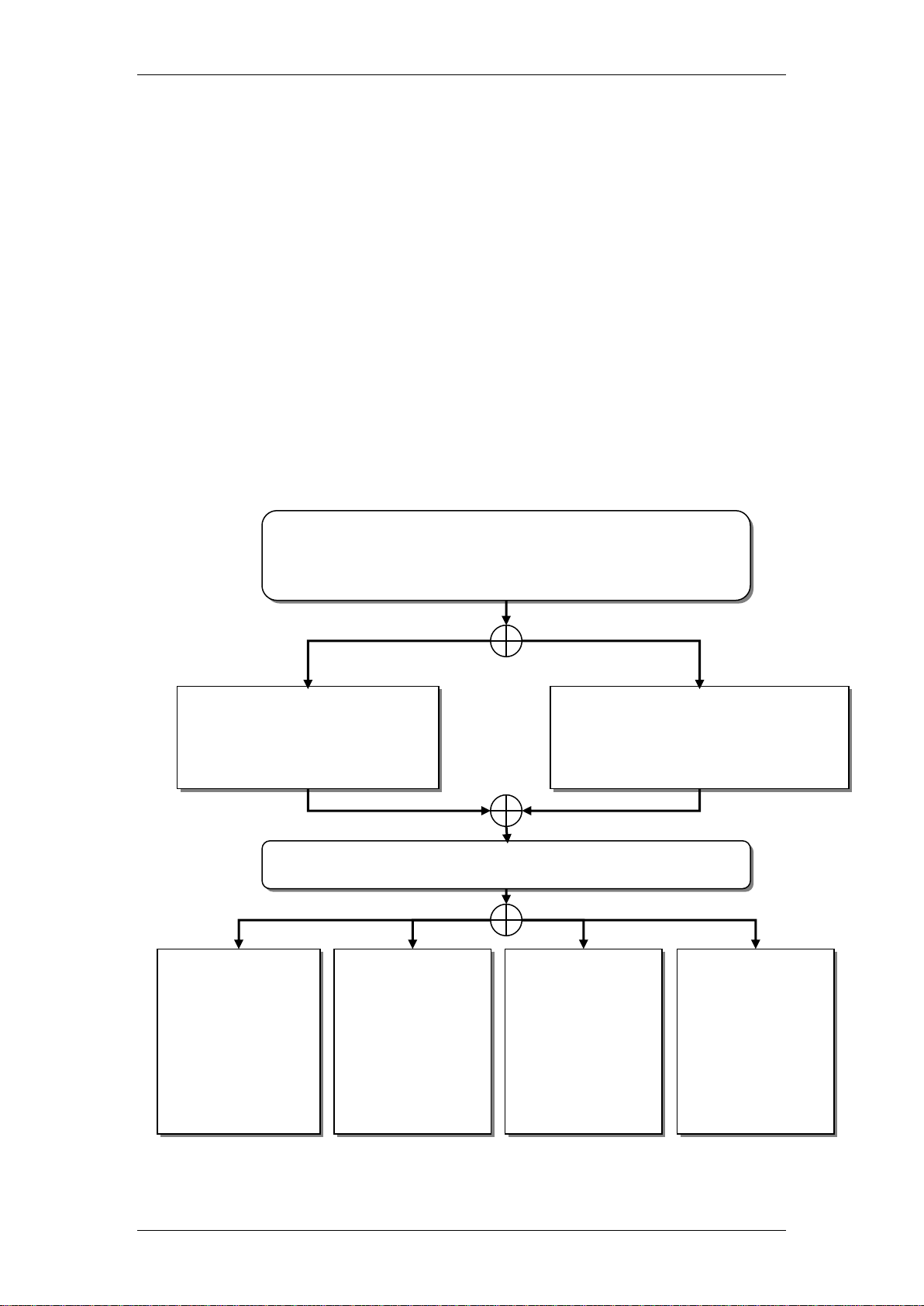
Do you want to enable/disable each alarm, or use a Profile to
determine which alarms are sent to the various
destinations/displays?
Refer to the Enabling or
Disabling Selected Alarms for
Each Destination/Display
section of this guide.
Refer to the Setting Alarm Profiles
for Destinations/Displays section
of this guide.
Which destinations/displays do you want to view alarms on?
Alarms can be
viewed in Element
Manager under the
Administration
tab, General
folder, and Alarms
link.
Refer to the
Setting the EMail Destination
section of this
guide. Alarms will
be sent to an email address.
Refer to the
Configuring
SNMP Trap
Destinations
section of this
guide. Alarms will
be sent to SNMP
software.
Refer to the
Specifying the
Alarm Set section
of this guide.
Alarms will be
displayed on a
telephone.
Individual Alarms
Use a Profile
EM GUI
E-Mail
SNMP
Alarm Set (DN)
Required Information
Before configuring the Alarm Service and Alarm Manager, the following
information is required:
Which alarms should do you want to be alerted to
How should an Administrator be notified of Alarms?
Flow Chart
The flow chart below shows a recommended order for configuring and viewing
system alarms.
6 NN40011-031 Issue 1.2 BCM Rls 6.0
Page 7
Alarm Manager
Configuration
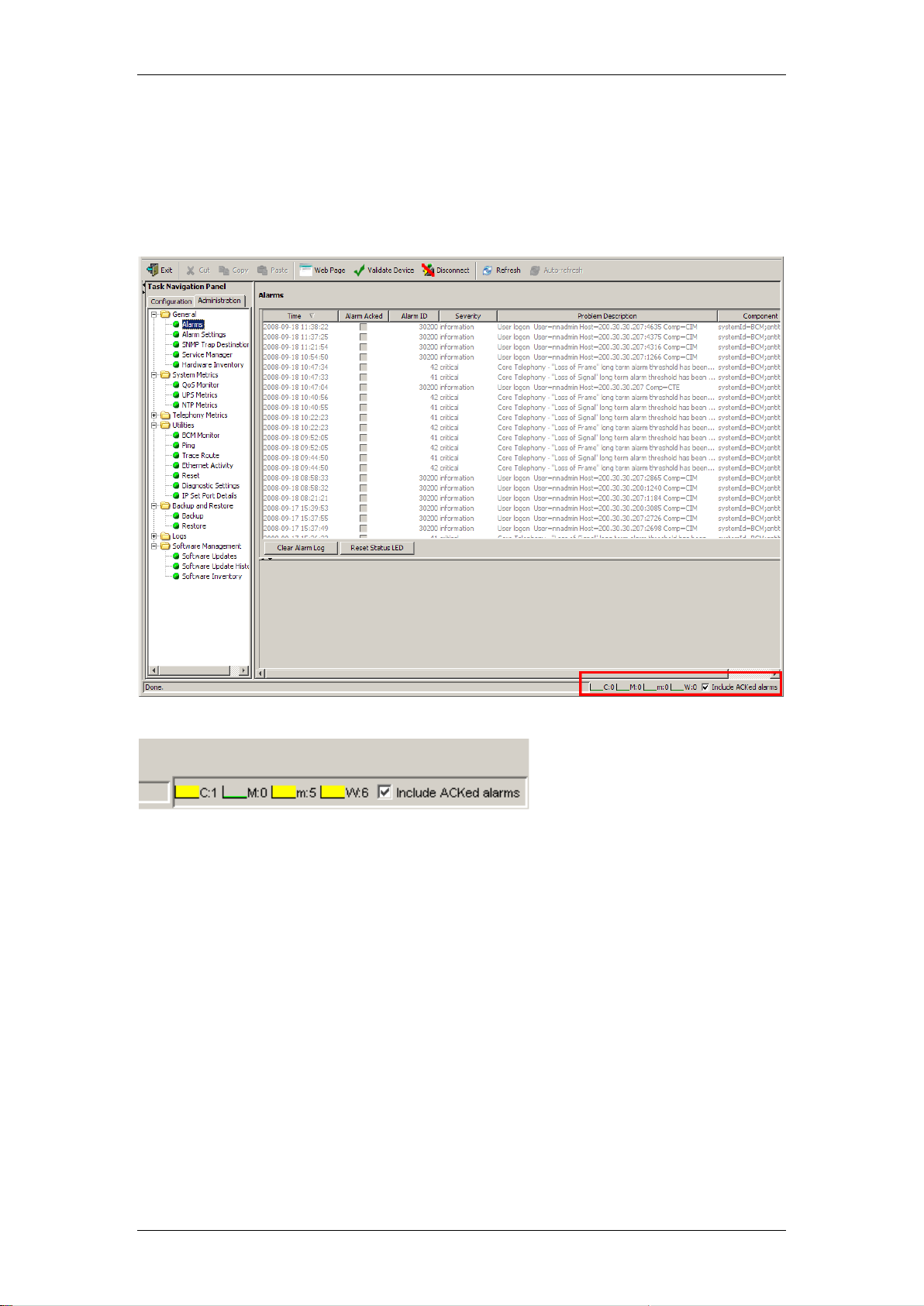
Alarm banner
The Alarm Banner is situated on the bottom task bar of the Element Manager
interface.
The Alarm Banner is visible at all times, so you do not have to navigate to the
Alarms panel to view alarms. If you notice a change in alarm conditions in the
Alarm Banner, for example a red mark in the Critical category, you can
navigate to the Alarms Panel to view the actual alarm.
The Alarm Banner provides counts of Critical, Major, Minor, and Warning
alarms; Information alarms are not included. You can specify whether to
include acknowledged alarms in the Alarm Banner.
Each alarm severity counter has a graph, which represents a sample of the
last 20 polling intervals. The graph has a colour to indicate a data change.
NN40011-031 Issue 1.2 BCM Rls 6.0 7
Page 8

Alarm Manager
The colours are as follows:
Green: There are no alarms of this severity, or there are alarms of this
severity but the count has decreased since the last polling interval.
Yellow: There are alarms of this severity, but they are older than at
least 1 polling interval.
Red: A new alarm has occurred since the last polling interval.
The BCM will scan for alarms every 30 seconds.
BCM Alarm Identification Numbers
You can view real-time alarm information using the Alarms screen in the BCM
Element Manager interface.
Alarms are generated by software components that are running on the BCM
system, and cover BCM services and applications.
Each component has a range of alarm IDs, so that each BCM alarm has a
unique alarm ID.
The Alarms can be viewed by selecting the Administration tab, opening the
General folder and clicking on the Alarms link.
Alarm Headings
Time - the date and time of the alarm
Alarm Acked tick box - indicates whether the alarm has been acknowledged
in the BCM Element Manager
Alarm ID - the unique alarm ID associated with the alarm
Severity - the severity of the alarm (Critical, Major, Minor, Warning, and
Information)
8 NN40011-031 Issue 1.2 BCM Rls 6.0
Page 9

Alarm Manager
BCM Component
Alarm ID Range
Core Telephony
0-999
Operating System
1000-1999
Software Updates
2000-2999
Persistent Data Repository
5000-5999
Date and Time
6000-6999
Modem Call Control
8000-8999
Service Manager
10000-10999
Platform Status Monitor
11000-11999
Backup and Restore
12000-12999
UPS
13000-13999
Configuration Change
16000-16999
System Set Based Admin
17000-17999
Startup Profile
19000-19999
System Authentication
30000-30999
Keycodes
31000-31999
Media Services Manager
40000-40999
CTE
41000-41999
Call Detail Recording
42000-42999
Voice CTI
43000-43999
IVR
46000-46999
Unistim Terminal Proxy Server
50000-50999
PVQM
50501-50999
VoIP Gateway
51000-51999
Media Path Server
52000-52999
Media Gateway Server
53000-53999
IP Telephony Provider
56000-56999
Survivable Remote Gateway
57000-57999
LAN Driver
60000-60999
ALG
64000-64999
Problem Description - a description of the alarm condition
Component ID - the process that has generated the alarm, in a 3-part format.
The component ID always identifies the system as a BCM, includes the name
of the system that generated the alarm, and identifies the component that
generated the alarm. In this way, remote monitoring stations can easily
identify what type of system generated an SNMP trap and which system
generated the trap.
Alarms are, sorted by date and time by default, with the newest at the top of
the table. The Alarms table displays from 100 to 1000 alarms.
The BCM’s LED’s
When an alarm condition occurs on the system, the Status LED on the front of
the BCM main unit changes to reflect the alarm condition. In normal operation,
both LEDs are green. All alarms with a severity of Major and Critical change
the Status LED to solid red on the BCM front panel, except in the event of a
Failed Startup Profile, which is indicated by a flashing red LED.
Using the BCM Element Manager, you can reset the Status LEDs on the front
panel of the BCM to a normal state.
Once the Status LED has changed to red in response to a Critical or Major
alarm condition, it remains in the alarmed state until you reset it using the
NN40011-031 Issue 1.2 BCM Rls 6.0 9
Page 10

Alarm Manager
BCM Element Manager. You would acknowledge the Alarm and then select
the Reset LED’s button the LED will then return to a Green state.
Alarm Settings
You may want to alter alarms from the default alarm status so that you can
reduce the number of alarms that are displayed in the Alarms table, sent via
SNMP traps, displayed on the Alarm set, or sent to e-mail destinations. You
can specify how alarms are handled, according to your needs.
You can specify the following settings for alarms:
The maximum number of alarms to display in the Alarms Panel (from
100 to 1000)
Whether to enable or disable SNMP traps for certain alarms; by default,
all Critical and Major alarms are sent as SNMP traps if you have
specified one or more trap destinations
Whether to display certain alarms in the Alarms table; by default all
Critical, Major, Minor, and Warning alarms are displayed in the Alarms
table
Whether to display certain alarms on the alarm set; by default, only
core telephony Critical and Major alarms are sent to this set
Whether to send certain alarms to an e-mail destination.
10 NN40011-031 Issue 1.2 BCM Rls 6.0
Page 11

Alarm Manager
Profiles can be set against the various alarm destination types, along the
following criteria:
Critical
Critical/Major
Critical/Major/Minor
All
None
The application of this facility would allow only Critical alarms to be sent to email destinations for example, or to stop sending alarms to the Alarm Set.
You can also test a selected alarm. This allows you to test whether the LED or
alarm displays/destinations are functioning as expected. Testing an alarm
generates an alarm in the system. Alarms generated using the Test Alarm
feature are identified in the Alarms table by the words "Test Event" in the
alarm Problem Description field.
Enabling or Disabling Selected Alarms for Each
Destination/Display
Use the following procedure to determine which alarms are sent to the various
destinations or displays, on a per alarm basis.
1. From the Administration tab open the General folder, and then click
the Alarm Settings link.
NN40011-031 Issue 1.2 BCM Rls 6.0 11
Page 12

Alarm Manager
2. In the Alarms table, select an alarm.
3. For each destination/display, i.e. GUI, e-mail, SNMP, or Alarm Set,
clear or tick the check box as appropriate. This will determine if the
selected alarm is sent to that destination/display.
4. A description of the alarm can also be viewed at the bottom of the
alarms panel.
12 NN40011-031 Issue 1.2 BCM Rls 6.0
Page 13

Alarm Manager
Setting Alarm Profiles for Destinations/Displays
As an alternative option to enabling or disabling alarms on a per
destination/display basis, it is possible to choose which type of alarm (Critical,
Major, Minor etc.) are sent to each destination/displays. It is also possible to
disable sending all alarms to selected destinations/displays, the Alarm Set
(telset display) for example.
1. From the Administration tab open the General folder, and then click
the Alarm Settings link.
2. From the Notification Type field, select the destination/display you
want to apply the Profile to.
NN40011-031 Issue 1.2 BCM Rls 6.0 13
Page 14

Alarm Manager
3. From the Profile selection field, select which types of alarms are to be
sent the selected destination/display.
4. Now click on the Set Filters button.
5. In this example, only Critical alarms will be sent to an e-mail
destination.
14 NN40011-031 Issue 1.2 BCM Rls 6.0
Page 15

Alarm Manager
Testing an Alarm
If you want to determine if alarms are being sent to the appropriate
destinations/displays, you can test the alarm using the following procedure.
Alarms generated using the Test Alarm feature are identified in the Alarms
table by the words "Test Event" in the alarm Problem Description field.
1. In the Alarms table, select an alarm.
2. Click the Test Alarm button.
3. In the Alarms table, "Test Event" is displayed in the alarm Problem
Description field.
NN40011-031 Issue 1.2 BCM Rls 6.0 15
Page 16

Alarm Manager
Setting the Destinations/Displays
In order for the alarms to be notified to the intended recipients, the various
destinations/displays should be set correctly.
Setting the E-Mail Destination
Use the following procedure to configure which e-mail address receives the
selected alarms.
1. In Element Manager, click on the Configuration tab. Open the
Administrator Access folder, and click on the E-Mail Settings link.
2. In the E-Mail settings area, click on the Add button.
16 NN40011-031 Issue 1.2 BCM Rls 6.0
Page 17

Alarm Manager
3. Enter the details of the e-mail server (SMTP server) and destination address.
Click OK when complete.
4. The account will be added to the list, and will be the destination for sending
the specified alarms to.
NN40011-031 Issue 1.2 BCM Rls 6.0 17
Page 18

Alarm Manager
Configuring SNMP Trap Destinations
Use the following procedure to configure which SNMP trap destinations will
receive the selected alarms. SNMP software is required at the destination to
view the alarm information.
1. In Element Manager, click on the Administration tab. Open the
General folder, and select the SNMP Trap Destinations link.
2. Click on the Add button at the bottom of the Trap Destinations
window.
18 NN40011-031 Issue 1.2 BCM Rls 6.0
Page 19
Alarm Manager
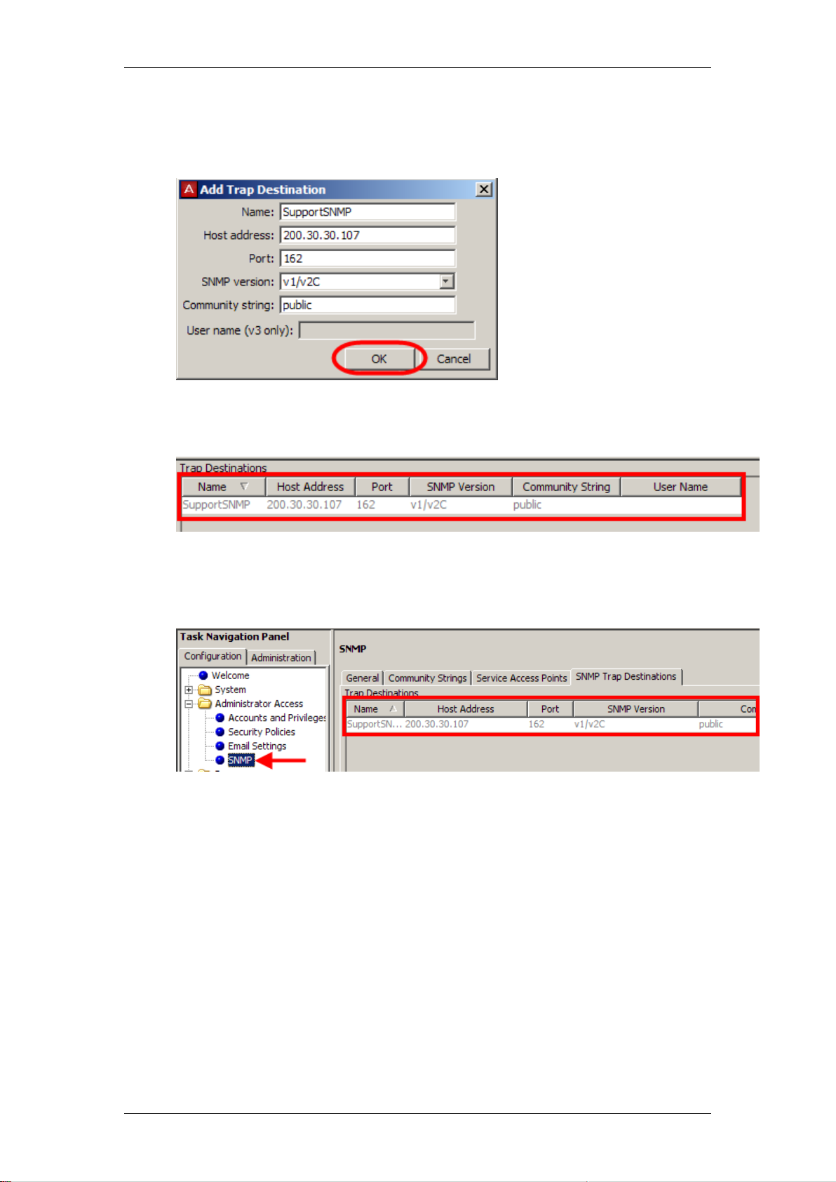
3. Enter the details of the SNMP destination (such as SNMP Host
address, SNMP version, and Community string), and click OK. The
Port number is entered as 162 by default.
4. The Trap Destination will be added to the list, and will be used as the
destination to send the selected alarms to.
5. This account will also be created in the main SNMP configuration area
under the Configuration tab, Administrator Access folder, SNMP
link, SNMP trap Destinations tab.
NN40011-031 Issue 1.2 BCM Rls 6.0 19
Page 20

Alarm Manager
Specifying the Alarm Set
Use the following procedure to specify which telset (DN) receives the selected
alarm information.
1. In Element Manager, click on the Configuration tab. Open the
Telephony folder, and select the Feature Settings link.
2. In the Feature Settings area, enter the required DN to receive the
selected alarms in the Alarm Set field.
3. The specified DN will now receive the selected alarms.
20 NN40011-031 Issue 1.2 BCM Rls 6.0
Page 21

Avaya Documentation Links
Fault and Performance Management
Alarm Manager
NN40011-031 Issue 1.2 BCM Rls 6.0 21
Page 22

Alarm Manager
22 NN40011-031 Issue 1.2 BCM Rls 6.0
 Loading...