

Avaya Advanced Gateway 2330, AG2330 Installation Manual

Installation — Hardware Components
Avaya Advanced Gateway 2330
NN47264-301, 01.01
August 2010
AG10.2.2

©
2010 Avaya Inc.
All Rights Reserved.
Notice
While reasonable efforts have been made to ensure that the
information in this document is complete and accurate at the time of
printing, Avaya assumes no liability for any errors. Avaya reserves the
right to make changes and corrections to the information in this
document without the obligation to notify any person or organization of
such changes.
Documentation disclaimer
Avaya shall not be responsible for any modifications, additions, or
deletions to the original published version of this documentation unless
such modifications, additions, or deletions were performed by Avaya.
End User agree to indemnify and hold harmless Avaya, Avaya's agents,
servants and employees against all claims, lawsuits, demands and
judgments arising out of, or in connection with, subsequent
modifications, additions or deletions to this documentation, to the
extent made by End User.
Link disclaimer
Avaya is not responsible for the contents or reliability of any linked Web
sites referenced within this site or documentation(s) provided by Avaya.
Avaya is not responsible for the accuracy of any information, statement
or content provided on these sites and does not necessarily endorse
the products, services, or information described or offered within them.
Avaya does not guarantee that these links will work all the time and has
no control over the availability of the linked pages.
Warranty
Avaya provides a limited warranty on this product. Refer to your sales
agreement to establish the terms of the limited warranty. In addition,
Avaya’s standard warranty language, as well as information regarding
support for this product, while under warranty, is available to Avaya
customers and other parties through the Avaya Support Web site:
http://www.avaya.com/support. Please note that if you acquired the
product from an authorized Avaya reseller outside of the United States
and Canada, the warranty is provided to you by said Avaya reseller and
not by Avaya.
Licenses
THE SOFTWARE LICENSE TERMS AVAILABLE ON THE AVAYA
WEBSITE,
APPLICABLE TO ANYONE WHO DOWNLOADS, USES AND/OR
INSTALLS AVAYA SOFTWARE, PURCHASED FROM AVAYA INC.,
ANY AVAYA AFFILIATE, OR AN AUTHORIZED AVAYA RESELLER
(AS APPLICABLE) UNDER A COMMERCIAL AGREEMENT WITH
AVAYA OR AN AUTHORIZED AVAYA RESELLER. UNLESS
OTHERWISE AGREED TO BY AVAYA IN WRITING, AVAYA DOES
NOT EXTEND THIS LICENSE IF THE SOFTWARE WAS OBTAINED
FROM ANYONE OTHER THAN AVAYA, AN AVAYA AFFILIATE OR AN
AVAYA AUTHORIZED RESELLER, AND AVAYA RESERVES THE
RIGHT TO TAKE LEGAL ACTION AGAINST YOU AND ANYONE
ELSE USING OR SELLING THE SOFTWARE WITHOUT A LICENSE.
BY INSTALLING, DOWNLOADING OR USING THE SOFTWARE, OR
AUTHORIZING OTHERS TO DO SO, YOU, ON BEHALF OF
YOURSELF AND THE ENTITY FOR WHOM YOU ARE INSTALLING,
DOWNLOADING OR USING THE SOFTWARE (HEREINAFTER
REFERRED TO INTERCHANGEABLY AS “YOU” AND “END USER”),
AGREE TO THESE TERMS AND CONDITIONS AND CREATE A
BINDING CONTRACT BETWEEN YOU AND AVAYA INC. OR THE
APPLICABLE AVAYA AFFILIATE (“AVAYA”).
Copyright
Except where expressly stated otherwise, no use should be made of
materials on this site, the Documentation(s) and Product(s) provided
by Avaya. All content on this site, the documentation(s) and the
product(s) provided by Avaya including the selection, arrangement and
design of the content is owned either by Avaya or its licensors and is
HTTP://SUPPORT.AVAYA.COM/LICENSEINFO/ ARE
protected
sui generis rights relating to the protection of databases. You may not
modify, copy, reproduce, republish, upload, post, transmit or distribute
in any way any content, in whole or in part, including any code and
software. Unauthorized reproduction, transmission, dissemination,
storage, and or use without the express written consent of Avaya can
be a criminal, as well as a civil, offense under the applicable law.
Third-party components
Certain software programs or portions thereof included in the Product
may contain software distributed under third party agreements (“Third
Party Components”), which may contain terms that expand or limit
rights to use certain portions of the Product (“Third Party Terms”).
Information regarding distributed Linux OS source code (for those
Products that have distributed the Linux OS source code), and
identifying the copyright holders of the Third Party Components and the
Third Party Terms that apply to them is available on the Avaya Support
Web site:
Trademarks
The trademarks, logos and service marks (“Marks”) displayed in this
site, the documentation(s) and product(s) provided by Avaya are the
registered or unregistered Marks of Avaya, its affiliates, or other third
parties. Users are not permitted to use such Marks without prior written
consent from Avaya or such third party which may own the Mark.
Nothing contained in this site, the documentation(s) and product(s)
should be construed as granting, by implication, estoppel, or otherwise,
any license or right in and to the Marks without the express written
permission of Avaya or the applicable third party.
Avaya is a registered trademark of Avaya Inc.
All other trademarks are the property of their respective owners.
Downloading documents
For the most current versions of documentation, see the Avaya Support
Web site:
Contact Avaya Support
Avaya provides a telephone number for you to use to report problems
or to ask questions about your product. The support telephone number
is 1-800-242-2121 in the United States. For additional support
telephone numbers, see the Avaya Web site:
support
by copyright and other intellectual property laws including the
http://www.avaya.com/support/Copyright/.
http://www.avaya.com/support
http://www.avaya.com/
2 Installation — Hardware Components August 2010

Contents
Chapter 1: Avaya Advanced Gateway 2330 safety precautions............................................5
Safety requirement for handling and installing modules...................................................................................5
Types of notices........................................................................................................................................5
Cautions and warnings for the Advanced Gateway 2330.........................................................................6
Foreign Exchange Station/Direct Inward Dial (FXS/DID) Interface Modules............................................7
Foreign Exchange Office/Centralized Automatic Message Accounting (FXO/CAMA) Interface Modules
..................................................................................................................................................................8
Personal safety and equipment protection........................................................................................................8
Module protection.....................................................................................................................................8
Cables and connectors protection............................................................................................................9
Electrostatic discharge.............................................................................................................................9
Antistatic material.....................................................................................................................................9
Chapter 2: New in this release................................................................................................11
Chapter 3: Introduction...........................................................................................................13
Prerequisites...................................................................................................................................................13
Navigation.......................................................................................................................................................13
Chapter 4: Avaya Advanced Gateway 2330 hardware components fundamentals...........15
Navigation.......................................................................................................................................................15
Interface modules for the AG2330..................................................................................................................15
T1/E1 Small Module...............................................................................................................................16
ISDN BRI S/T and ISDN BRI U Small Modules......................................................................................17
FXS/DID Small Module...........................................................................................................................19
FXO/CAMA Small Module......................................................................................................................21
Compatible internal modules for Avaya Advanced Gateway 2330.................................................................23
Replaceable parts for Avaya Advanced Gateway 2330..................................................................................24
Chapter 5: Installing Avaya Advanced Gateway 2330 hardware components..................27
Navigation.......................................................................................................................................................27
Installing the interface modules.......................................................................................................................27
Prerequisites...........................................................................................................................................28
Installing a Small Module........................................................................................................................28
Hot swapping interface modules.....................................................................................................................28
Connecting the optional external power supply..............................................................................................30
Connecting Avaya Advanced Gateway 2330 power cables............................................................................31
Connecting AC power cables.................................................................................................................31
Connecting the console port cable..................................................................................................................32
Removing the AG2330 top cover....................................................................................................................33
Replacing the internal PVIM module...............................................................................................................34
Replacing the AG2330 DDR2 SO-DIMM........................................................................................................35
Replacing the AG2330 internal Compact Flash..............................................................................................37
Installation — Hardware Components August 2010 3

Chapter 6: Environmental requirements...............................................................................39
Chapter 7: Interface connector pin assignments.................................................................41
Chapter 8: Hardware reliability...............................................................................................45
Chapter 9: Translations of safety messages........................................................................47
Class A device caution statement translations................................................................................................47
Qualified service personnel warning statement..............................................................................................48
Overcurrent warning statement.......................................................................................................................48
Cover plate warning statement.......................................................................................................................49
Power cord warning statement........................................................................................................................50
Index.........................................................................................................................................53
4 Installation — Hardware Components August 2010
Chapter 1: Avaya Advanced Gateway 2330
safety precautions
Safety requirement for handling and installing modules
This section provides the information necessary for the proper and safe handling of hardware
components for the Avaya Advanced Gateway 2330 (AG2330). Please read and apply this
information to all aspects of the instructions in this manual.
Types of notices
Notice paragraphs alert you about issues that require your attention. The following paragraphs
describe the types of notices used in this guide. For translations of safety messages, see
Translations of safety messages on page 47.
Important:
An attention notice provides important information regarding the installation and operation
of Avaya products.
Electrostatic alert:
ESD
ESD notices provide information about how to avoid discharge of static electricity and
subsequent damage to Avaya products.
Caution:
Caution notices provide information about how to avoid possible service disruption or
damage to Avaya products.
Warning:
Warning notices provide information about how to avoid personal injury when working with
Avaya products.
Installation — Hardware Components August 2010 5
Avaya Advanced Gateway 2330 safety precautions
Voltage:
Danger—High Voltage notices provide information about how to avoid a situation or
condition that can cause serious personal injury or death from high voltage or electric shock.
Danger:
Danger notices provide information about how to avoid a situation or condition that can
cause serious personal injury or death.
Cautions and warnings for the Advanced Gateway 2330
The following precautionary messages apply to the Advanced Gateway 2330. For your safety,
read these precautions carefully before proceeding with installation of the product.
Warning:
Only qualified service personnel must perform the installation. Read and follow all warning
notices and instructions marked on the product or included in the documentation.
Warning:
This product relies on the building installation for overcurrent protection. Ensure that a fuse
or circuit breaker no larger than 120 V AC, 15 A U.S. (240 V AC, 10 A international) is used on
the phase conductors.
Caution:
To reduce the risk of fire, use only number 26 AWG or larger UL Listed or CSA Certified
Telecommunication Line Cord for all network connections.
Caution:
Risk of explosion if battery is replaced by an incorrect type. Dispose of used batteries
according to the instructions.
Hardware Notice
The Lithium battery in this product is part of a non-volatile memory device and will retain data for
10 years in the absence of power. Avaya does not consider the lithium battery in this unit a
field replaceable or serviceable part and should not be accessed by the customer.
Voltage:
Risk of injury by electric shock
Before working on this equipment, be aware of good safety practices and the hazards
involved with electrical circuits. Use only power cords that have a grounding path. Ensure
the switch is properly grounded before powering on the unit.
6 Installation — Hardware Components August 2010
Safety requirement for handling and installing modules
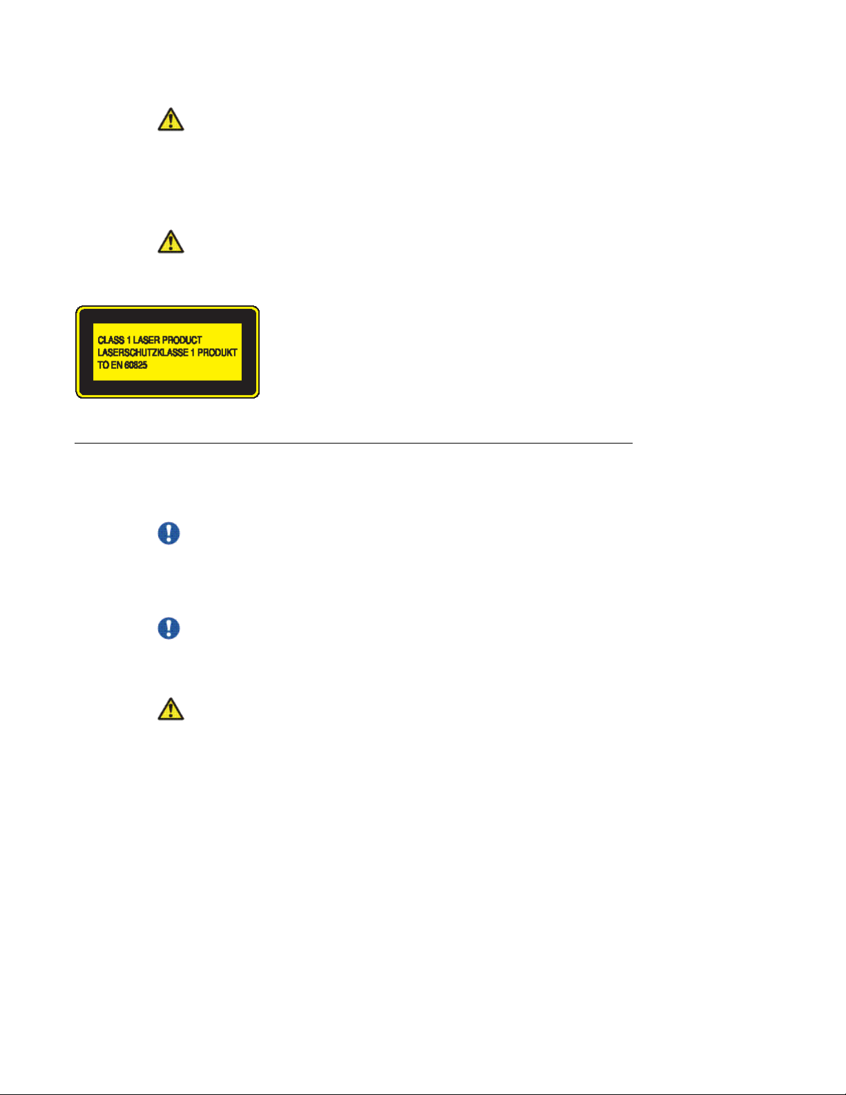
Warning:
Risk of eye injury by laser
Fiber optic equipment can emit laser or infrared light that can injure your eyes. Never look
into an optical fiber or connector port. Always assume that fiber optic cables are connected to
a light source.
Caution:
If you do not install interface modules in slots, keep the metal cover plates in place over the
slots. Removing the cover plates impedes airflow and proper cooling of the unit.
Foreign Exchange Station/Direct Inward Dial (FXS/DID) Interface Modules
Important:
Ensure you use standard straight-through RJ11 modular telephone cables with FXS/DID
interface modules. TIP must connect to TIP and RING must connect to RING. FXS/DID
ground start does not work if polarity is reversed.
Important:
Avaya does not support FXS/DID port connections leaving the building. Use FXS/DID
connections for intra-building purposes only.
Warning:
The 2- and 4-port FXS/DID interface modules have a ring signal generator that is a source of
hazardous voltage. Do not touch the RJ11 port conductors, the conductors of a cable (that
is, the exposed metal ends of a cable connector) connected to the RJ11 port, or the circuit
board when the ringer is active (an incoming call activates the ringer).
Installation — Hardware Components August 2010 7
Avaya Advanced Gateway 2330 safety precautions
Foreign Exchange Office/Centralized Automatic Message Accounting (FXO/CAMA) Interface Modules
Important:
Ensure you use standard straight-through RJ11 modular telephone cables with FXO/
CAMA interface modules. TIP must connect to TIP and RING must connect to RING.
Warning:
The 2-port and 4-port FXO/CAMA interface modules can receive a ring signal that is a source
of hazardous voltage. Do not touch the RJ11 port conductors or the conductors of a cable
(the exposed metal ends of a cable connector) connected to the RJ11 port.
Personal safety and equipment protection
Read this section to prevent injury and equipment damage.
Module protection
The following practices prevent equipment damage when you work on the AG2330:
• Always wear a grounded antistatic wrist strap when you handle modules.
• Always set modules on appropriate antistatic material.
• Handle modules by the faceplate and handles. Do not touch pins or electrical connections.
• Do not leave interface module or power supply module slots empty. You must fill all slots
with modules or slot covers to maintain safety compliance, proper cooling, and
electromagnetic interference (EMI) containment in the shelf.
• Ensure that your environment meets the requirements for temperature, humidity, and
cleanliness. See
• Do not overtighten thumb screws or lug nuts. Tighten screws and nuts until they are snug,
plus a quarter turn. If you use a power tool to tighten screws, use a low torque setting
of 2 to 3 in–lb (0.226 to 0.339 N-m).
Environmental requirements on page 39.
8 Installation — Hardware Components August 2010

Cables and connectors protection
The following practices prevent damage to cables and connectors:
• Use caution when connecting cables. Take care to ensure you insert each cable connector
in the correct port for the purpose you intend. For example, ensure you connect LAN
cables and connectors to LAN ports on the AG2330.
• Support cables to prevent stress on the connectors. If you have a high-density cable
configuration, use an appropriate cable management system to relieve stress on the
cables. Also ensure that cables are threaded neatly, and that you employ cable ties as
required.
• Do not exceed the bend radius recommended for the type of cable installed.
• Fiber-optic cables and connectors require special care:
- Cover connectors with rubber safety plugs when they are not connected.
- Before you install or replace fiber-optic cables, clean the connectors.
Personal safety and equipment protection
- Do not exceed the bend radius that is recommended for fiber-optic cable. The
acceptable bend radius for fiber-optic cable is ten times its diameter, or 2.5 to 5 cm (1
to 2 in.). If you use a radius of less than the recommended bend radius, a loss of
signal integrity can result. Loss of signal integrity caused by incorrect bend radius is
difficult to diagnose.
Electrostatic discharge
Electrostatic discharge (ESD) is the transfer of charge between objects at different electrical
potentials. ESD can change the electrical characteristics of a semiconductor device, and
degrade or destroy it. ESD can cause equipment to malfunction or fail.
To dissipate or neutralize electrostatic charges, use proper grounding and use conductive or
dissipative materials.
Use a grounded ESD wrist strap. When you use a wrist strap, any charge in your body can
go to ground rather than damage a hardware module.
When shipping the product, proper antistatic packaging shields the product from charge
caused by movement of the product within the shipping container.
Antistatic material
Antistatic material prevents electrical damage to equipment and therefore prevents the
interruption of normal operations in an electronic system.
Installation — Hardware Components August 2010 9

Avaya Advanced Gateway 2330 safety precautions
Place modules on an appropriate antistatic material when you replace hardware.
Use an ESD pad or antistatic packaging.
Important:
Some antistatic packaging is effective only on the inside of the package.
10 Installation — Hardware Components August 2010

Chapter 2: New in this release
Avaya Advanced Gateway 2330 Installation — Hardware Components is a new document for Release
10.2.2.
Installation — Hardware Components August 2010 11

New in this release
12 Installation — Hardware Components August 2010

Chapter 3: Introduction
This installation guide provides basic instruction on how to install and replace the hardware components
for the Avaya Advanced Gateway 2330 (AG2330).
Prerequisites
The installation of the AG2330 in the equipment rack is complete.
Navigation
• Avaya Advanced Gateway 2330 hardware components fundamentals on page 15
• Installing Avaya Advanced Gateway 2330 hardware components on page 27
• Environmental requirements on page 39
•
Interface connector pin assignments on page 41
• Translations of safety messages on page 47
Installation — Hardware Components August 2010 13

Introduction
14 Installation — Hardware Components August 2010

Chapter 4: Avaya Advanced Gateway 2330
hardware components
fundamentals
This section provides an overview of the Avaya Advanced Gateway 2330 hardware components.
For information about installing the AG2330 chassis, see Avaya Advanced Gateway 2330 Installation —
Chassis (NN47264-304).
For information about initial configuration of the AG2330, see Avaya Advanced Gateway 2330
Commissioning (NN47264-302).
Navigation
Interface modules for the AG2330 on page 15
•
•
Compatible internal modules for Avaya Advanced Gateway 2330 on page 23
• Replaceable parts for Avaya Advanced Gateway 2330 on page 24
Interface modules for the AG2330
For detailed information about the AG2330 interface modules, the supported features and
functions of each module, and instructions for configuring features, see the following books:
• Avaya Advanced Gateway 2330 Configuration — SIP Media Gateway (NN47264-508)
• Avaya Advanced Gateway 2330 Configuration — Ethernet (NN47264-501)
Avaya provides the following optional interface modules for the AG2330:
• 1-port T1/E1 Small Module
• 2-port T1/E1 Small Module
• 2-port ISDN BRI ST Small Module
• 2-port ISDN BRI U Small Module
• 2-port Foreign Exchange Station/Direct Inward Dialing (FXS/DID) Small Module
• 4-port FXS/DID Small Module
Installation — Hardware Components August 2010 15
Avaya Advanced Gateway 2330 hardware components fundamentals
• 2-port Foreign Exchange Office/Centralized Automatic Message Accounting (FXO/
CAMA) Small Module
• 4-port FXO/CAMA Small Module
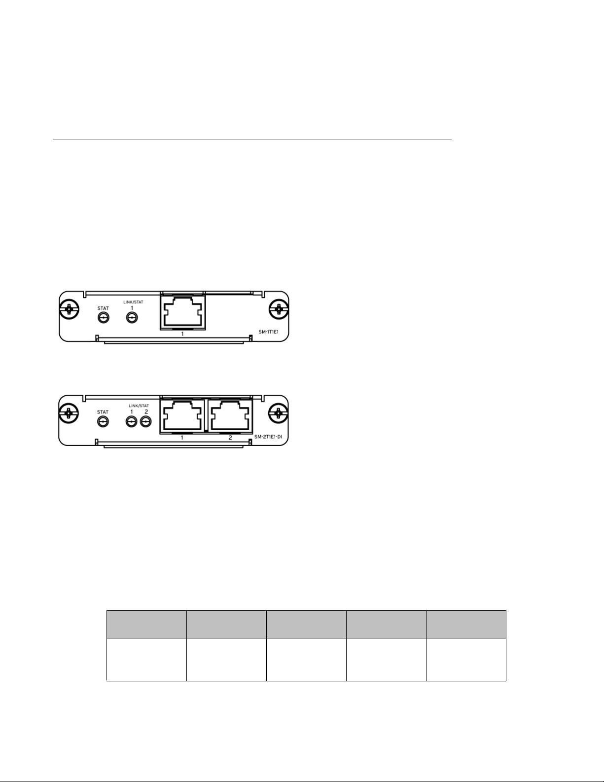
T1/E1 Small Module
Avaya offers the T1/E1 Small Module with one or two ports.
You can install the 1- and 2-port T1/E1 Small Modules in any of the Small Module slots on the
AG2330 chassis.
You can use the T1/E1 Small Modules for voice connections. You can configure each port on
the 2-port T1/E1 Small Module in voice mode.
The following figures show the two types of T1/E1 Small Modules.
Figure 1: 1-port T1/E1 Small Module
Figure 2: 2-port T1/E1 Small Module
In voice mode, the T1/E1 Small Module supports Channel Associated Signaling (CAS) to
provide the AG2330 with connections to the Public Switched Telephone Network (PSTN).
You can also configure the 1- and 2-port T1/E1 Small Modules to operate as Integrated
Services Digital Network (ISDN) primary rate interface (PRI) connections, providing 23 (T1) or
30 (E1) bearer channels (B-channel) for data and 1 D-channel for signaling.
The 2-port T1/E1 Small Module provides either two T1 ports or two E1 ports.
Table 1: Cable and connectors
Port Connector Recommended
T1/E1 RJ45 T1: Dual
cable type
shielded twisted
pair, 100 ohm,
Minimum cable
length
None T1: DSX1
Maximum cable
length
(interior) from 0
to 655 ft. DS1
16 Installation — Hardware Components August 2010
 Loading...