

Page 1

Administering Avaya Aura® Session
Manager
November 2010
Issue 1.1
03-603324
Release 6.1
Page 2

©
2010 Avaya Inc.
All Rights Reserved.
Notice
While reasonable efforts have been made to ensure that the
information in this document is complete and accurate at the time of
printing, Avaya assumes no liability for any errors. Avaya reserves the
right to make changes and corrections to the information in this
document without the obligation to notify any person or organization of
such changes.
Documentation disclaimer
“Documentation” means information published by Avaya in varying
mediums which may include product information, operating instructions
and performance specifications that Avaya generally makes available
to users of its products. Documentation does not include marketing
materials. Avaya shall not be responsible for any modifications,
additions, or deletions to the original published version of
documentation unless such modifications, additions, or deletions were
performed by Avaya. End User agrees to indemnify and hold harmless
Avaya, Avaya's agents, servants and employees against all claims,
lawsuits, demands and judgments arising out of, or in connection with,
subsequent modifications, additions or deletions to this documentation,
to the extent made by End User.
Link disclaimer
Avaya is not responsible for the contents or reliability of any linked Web
sites referenced within this site or documentation provided by Avaya.
Avaya is not responsible for the accuracy of any information, statement
or content provided on these sites and does not necessarily endorse
the products, services, or information described or offered within them.
Avaya does not guarantee that these links will work all the time and has
no control over the availability of the linked pages.
Warranty
Avaya provides a limited warranty on its Hardware and Software
(“Product(s)”). Refer to your sales agreement to establish the terms of
the limited warranty. In addition, Avaya’s standard warranty language,
as well as information regarding support for this Product while under
warranty is available to Avaya customers and other parties through the
Avaya Support Web site:
you acquired the Product(s) from an authorized Avaya reseller outside
of the United States and Canada, the warranty is provided to you by
said Avaya reseller and not by Avaya.
Licenses
THE SOFTWARE LICENSE TERMS AVAILABLE ON THE AVAYA
WEBSITE,
APPLICABLE TO ANYONE WHO DOWNLOADS, USES AND/OR
INSTALLS AVAYA SOFTWARE, PURCHASED FROM AVAYA INC.,
ANY AVAYA AFFILIATE, OR AN AUTHORIZED AVAYA RESELLER
(AS APPLICABLE) UNDER A COMMERCIAL AGREEMENT WITH
AVAYA OR AN AUTHORIZED AVAYA RESELLER. UNLESS
OTHERWISE AGREED TO BY AVAYA IN WRITING, AVAYA DOES
NOT EXTEND THIS LICENSE IF THE SOFTWARE WAS OBTAINED
FROM ANYONE OTHER THAN A V A Y A, AN A V A Y A AFFILIA TE OR AN
AVAYA AUTHORIZED RESELLER; AVAYA RESERVES THE RIGHT
TO TAKE LEGAL ACTION AGAINST YOU AND ANYONE ELSE
USING OR SELLING THE SOFTWARE WITHOUT A LICENSE. BY
INSTALLING, DOWNLOADING OR USING THE SOFTWARE, OR
AUTHORIZING OTHERS TO DO SO, YOU, ON BEHALF OF
YOURSELF AND THE ENTITY FOR WHOM YOU ARE INSTALLING,
DOWNLOADING OR USING THE SOFTWARE (HEREINAFTER
REFERRED TO INTERCHANGEABL Y AS “YOU” AND “END USER”),
AGREE TO THESE TERMS AND CONDITIONS AND CREATE A
BINDING CONTRACT BETWEEN YOU AND AVAYA INC. OR THE
APPLICABLE AVAYA AFFILIATE (“AVAYA”).
Avaya grants End User a license within the scope of the license types
described below. The applicable number of licenses and units of
capacity for which the license is granted will be one (1), unless a
HTTP://SUPPORT.AVAYA.COM/LICENSEINFO/ ARE
http://support.avaya.com. Please note that if
different number of licenses or units of capacity is specified in the
Documentation or other materials available to End User. “Designated
Processor” means a single stand-alone computing device. “Server”
means a Designated Processor that hosts a software application to be
accessed by multiple users. “Software” means the computer programs
in object code, originally licensed by Avaya and ultimately utilized by
End User, whether as stand-alone Products or pre-installed on
Hardware. “Hardware” means the standard hardware originally sold by
Avaya and ultimately utilized by End User.
Concurrent User License
Concurrent User License (CU). End User may install and use the
Software on multiple Designated Processors or one or more Servers,
so long as only the licensed number of Units are accessing and using
the Software at any given time. A “Unit” means the unit on which Avaya,
at its sole discretion, bases the pricing of its licenses and can be,
without limitation, an agent, port or user, an e-mail or voice mail account
in the name of a person or corporate function (e.g., webmaster or
helpdesk), or a directory entry in the administrative database utilized
by the Software that permits one user to interface with the Software.
Units may be linked to a specific, identified Server.
Copyright
Except where expressly stated otherwise, no use should be made of
materials on this site, the Documentation, Software, or Hardware
provided by Avaya. All content on this site, the documentation and the
Product provided by Avaya including the selection, arrangement and
design of the content is owned either by Avaya or its licensors and is
protected by copyright and other intellectual property laws including the
sui generis rights relating to the protection of databases. You may not
modify, copy, reproduce, republish, upload, post, transmit or distribute
in any way any content, in whole or in part, including any code and
software unless expressly authorized by Avaya. Unauthorized
reproduction, transmission, dissemination, storage, and or use without
the express written consent of Avaya can be a criminal, as well as a
civil offense under the applicable law.
Third-party components
Certain software programs or portions thereof included in the Product
may contain software distributed under third party agreements (“Third
Party Components”), which may contain terms that expand or limit
rights to use certain portions of the Product (“Third Party Terms”).
Information regarding distributed Linux OS source code (for those
Products that have distributed the Linux OS source code), and
identifying the copyright holders of the Third Party Components and the
Third Party Terms that apply to them is available on the A vaya Support
Web site:
Preventing Toll Fraud
“T oll fraud” is the unauthorized use of your telecommunications system
by an unauthorized party (for example, a person who is not a corporate
employee, agent, subcontractor, or is not working on your company's
behalf). Be aware that there can be a risk of Toll Fraud associated with
your system and that, if Toll Fraud occurs, it can result in substantial
additional charges for your telecommunications services.
Avaya Toll Fraud Intervention
If you suspect that you are being victimized by T oll Fraud and you need
technical assistance or support, call Technical Service Center Toll
Fraud Intervention Hotline at +1-800-643-2353 for the United States
and Canada. For additional support telephone numbers, see the Avaya
Support Web site:
vulnerabilities with Avaya products should be reported to Avaya by
sending mail to: securityalerts@avaya.com.
Trademarks
Avaya® and Avaya Aura® are registered trademarks of Avaya Inc. in
the United States of America and/or other jurisdictions.
All non-Avaya trademarks are the property of their respective owners,
and “Linux” is a registered trademark of Linus Torvalds.
http://support.avaya.com/Copyright.
http://support.avaya.com. Suspected security
2 Administering Avaya Aura® Session Manager November 2010
Comments? infodev@avaya.com
Page 3

Downloading Documentation
For the most current versions of Documentation, see the Avaya
Support Web site: http://support.avaya.com.
Contact Avaya Support
Avaya provides a telephone number for you to use to report problems
or to ask questions about your Product. The support telephone number
is 1-800-242-2121 in the United States. For additional support
telephone numbers, see the Avaya W eb site:
http://support.avaya.com.
Administering Avaya Aura® Session Manager November 2010 3
Page 4

4 Administering Avaya Aura® Session Manager November 2010
Comments? infodev@avaya.com
Page 5

Contents
Chapter 1: Getting started..................................................................................................
Introduction...............................................................................................................................................
Overview of System Manager...................................................................................................................
Log on to System Manager.......................................................................................................................
Logging on to System Manager Web interface................................................................................
Login information for users with user name admin...........................................................................
Password and security policies for users with username admin...............................................................
Password aging policy enforcement.................................................................................................
Password strength policy enforcement............................................................................................
Password history policy enforcement...............................................................................................
Password lockout policy enforcement..............................................................................................
Inactive session termination policy...................................................................................................
Logon warning banner......................................................................................................................
Editing password policies.................................................................................................................
Editing Session Properties...............................................................................................................
Security settings...............................................................................................................................
Editing the login warning banner......................................................................................................
Password policies field descriptions.................................................................................................
Session Properties field descriptions...............................................................................................
SIP Application Server..............................................................................................................................
Overview of SIP Application Server.................................................................................................
Starting the SIP Application Server management console...............................................................
SIP A/S Connection Details field descriptions..................................................................................
About SIP Application Server Management Console.......................................................................
Viewing Service Director Statistics...................................................................................................
Statistics: Service Directors field descriptions..................................................................................
Service Director Statistics field descriptions.....................................................................................
Viewing Service Host Instance Statistics..........................................................................................
Statistics: Service Hosts field descriptions.......................................................................................
Service Host Statistics field descriptions..........................................................................................
Chapter 2: Synchronizing Communication Manager and messaging data with System
Manager...............................................................................................................................
Introduction...............................................................................................................................................
Creating a Communication Manager instance..........................................................................................
Creating a messaging instance.................................................................................................................
Initializing Synchronization........................................................................................................................
Synchronizing Messaging Data................................................................................................................
Manage Elements field descriptions.........................................................................................................
Application Details field descriptions.........................................................................................................
Chapter 3: Managing Security...........................................................................................
Introduction...............................................................................................................................................
Setting SCEP enrollment password..........................................................................................................
Adding a Session Manager application.....................................................................................................
Viewing trusted certificates.......................................................................................................................
13
13
13
15
15
16
17
17
17
18
18
18
18
19
19
20
20
20
22
23
23
23
24
24
25
25
26
27
27
29
31
31
31
32
33
33
33
35
43
43
43
44
44
Administering Avaya Aura® Session Manager November 2010 5
Page 6

Adding trusted certificates.........................................................................................................................
Exporting the Session Manager Certificate...............................................................................................
Removing trusted certificates....................................................................................................................
Refreshing CA Certificate List...................................................................................................................
Viewing identity certificates.......................................................................................................................
Enrollment Password field descriptions....................................................................................................
Manage Elements field descriptions.........................................................................................................
Application Details field descriptions.........................................................................................................
Trusted Certificates field descriptions.......................................................................................................
Add Trusted Certificate field descriptions..................................................................................................
View Trust Certificate field descriptions....................................................................................................
Delete Trusted Certificate Confirmation field descriptions........................................................................
Identity Certificates field descriptions........................................................................................................
Chapter 4: Managing Users................................................................................................
Introduction...............................................................................................................................................
Adding users.............................................................................................................................................
Managing communication profiles............................................................................................................
Creating a new communication profile.............................................................................................
Deleting a communication profile.....................................................................................................
Creating a new communication address for a communication profile..............................................
Modifying a communication address of a communication profile.....................................................
Deleting a communication address from a communication profile...................................................
Session Manager Communication profile administration.................................................................
Station and Messaging profiles of a user.........................................................................................
Adding a messaging profile for a user..............................................................................................
Modifying a messaging profile of a user...........................................................................................
Removing association between a subscriber mailbox and a user....................................................
Deleting a subscriber mailbox..........................................................................................................
Adding an endpoint profile for a user...............................................................................................
Modifying a endpoint profile of a user..............................................................................................
Removing association between an endpoint and a user..................................................................
Deleting an endpoint profile of a user...............................................................................................
Modifying user accounts...........................................................................................................................
Viewing details of a user...........................................................................................................................
Removing user accounts...........................................................................................................................
Creating duplicate users...........................................................................................................................
Filtering users............................................................................................................................................
Searching for users...................................................................................................................................
Viewing deleted users...............................................................................................................................
Restoring a deleted user...........................................................................................................................
New User Profile field descriptions...........................................................................................................
User Profile Edit field descriptions............................................................................................................
User Profile View field descriptions...........................................................................................................
User Delete Confirmation field descriptions..............................................................................................
Managing bulk importing and exporting....................................................................................................
Bulk importing users.........................................................................................................................
Scheduling a user import job............................................................................................................
45
46
47
47
48
48
49
50
56
57
59
60
60
63
63
64
67
67
67
68
69
69
70
70
71
72
73
73
74
75
76
76
77
78
78
79
79
80
81
81
82
92
103
111
111
111
113
6 Administering Avaya Aura® Session Manager November 2010
Page 7

Aborting a user import job on first error............................................................................................
Canceling a user import job..............................................................................................................
Deleting an importing job..................................................................................................................
Viewing a user importing job in Scheduler.......................................................................................
Viewing details of a user importing job.............................................................................................
List of XML Schema Definitions and sample XMLs for bulk import..................................................
Attribute details defined in Import user XSD....................................................................................
Attribute details defined in Delete User XSD....................................................................................
Attribute details defined in the Endpoint profile XSD........................................................................
Attribute details defined in the Messaging communication profile XSD...........................................
Attribute details defined in the Session Manager communication profile XSD.................................
Import Users field descriptions.........................................................................................................
Import Users – Job Details field descriptions...................................................................................
Job Details field descriptions............................................................................................................
Quick start to importing users...........................................................................................................
Chapter 5: Managing Session Manager routing...............................................................
Overview of Session Manager routing......................................................................................................
Prerequisites for Routing Setup................................................................................................................
Routing......................................................................................................................................................
Routing.............................................................................................................................................
Routing of a call using routing policy data........................................................................................
Administering initial setup of the Session Manager..........................................................................
Routing import and export Overview................................................................................................
Saving, Committing, and Synchronizing configuration changes......................................................
Duplicating Routing entity data.........................................................................................................
Domains....................................................................................................................................................
About Domains.................................................................................................................................
Creating domains.............................................................................................................................
Modifying domains...........................................................................................................................
Deleting domains..............................................................................................................................
Delete Confirmation field descriptions..............................................................................................
Domain Management field descriptions...........................................................................................
Domain Details field descriptions.....................................................................................................
Bulk import for Domains...................................................................................................................
Locations...................................................................................................................................................
About Locations................................................................................................................................
Creating Locations...........................................................................................................................
Modifying Locations..........................................................................................................................
Deleting Locations............................................................................................................................
Delete Confirmation field descriptions..............................................................................................
CAC Overview..................................................................................................................................
Location field descriptions................................................................................................................
Location Details field descriptions....................................................................................................
Bulk import for Locations..................................................................................................................
Adaptations...............................................................................................................................................
About Adaptations............................................................................................................................
Adaptation module administration....................................................................................................
114
114
115
115
115
116
172
181
183
210
219
221
225
226
227
235
235
236
236
236
237
237
238
242
242
242
242
243
243
244
244
244
245
246
246
246
247
248
248
249
249
253
254
257
258
258
259
Administering Avaya Aura® Session Manager November 2010 7
Page 8

Creating Adaptations........................................................................................................................
Adaptation example..........................................................................................................................
Modifying Adaptations......................................................................................................................
Deleting Adaptations........................................................................................................................
Delete Confirmation field descriptions..............................................................................................
Installed vendor adapters.................................................................................................................
Adaptations field descriptions...........................................................................................................
Adaptation Details field descriptions................................................................................................
Bulk import for Adaptations..............................................................................................................
SIP Entities................................................................................................................................................
About SIP Entities............................................................................................................................
Authentication of trusted SIP entities...............................................................................................
IP and transport layer validation.......................................................................................................
TLS layer validation..........................................................................................................................
Creating SIP Entities........................................................................................................................
Modifying SIP entities.......................................................................................................................
Deleting SIP Entities.........................................................................................................................
Delete Confirmation field descriptions..............................................................................................
SIP Entities field descriptions...........................................................................................................
SIP Entity Details field descriptions..................................................................................................
SIP Entity List field descriptions.......................................................................................................
Bulk import for SIP Entities...............................................................................................................
SIP Entity References...............................................................................................................................
About SIP Entity References............................................................................................................
Displaying SIP Entity References.....................................................................................................
Overview of References to SIP Entities field descriptions................................................................
Entity Links................................................................................................................................................
About Entity Links.............................................................................................................................
Creating Entity Links........................................................................................................................
Modifying entity links........................................................................................................................
Deleting Entity Links.........................................................................................................................
Delete Confirmation field descriptions..............................................................................................
Entity Links field descriptions...........................................................................................................
Bulk import for Entity Links...............................................................................................................
Time Ranges.............................................................................................................................................
About the Time Ranges....................................................................................................................
Creating Time Ranges......................................................................................................................
Modifying Time Ranges....................................................................................................................
Deleting Time Ranges......................................................................................................................
Delete Confirmation field descriptions..............................................................................................
Time Ranges field descriptions........................................................................................................
Time Range List field descriptions....................................................................................................
Bulk import for Time Ranges............................................................................................................
Routing Policies........................................................................................................................................
About Routing Policies.....................................................................................................................
Creating Routing Policies.................................................................................................................
Modifying Routing Policies...............................................................................................................
261
263
265
267
267
268
271
272
275
276
276
277
277
277
278
280
282
282
282
284
286
286
289
289
289
289
290
290
291
291
292
292
292
294
294
294
295
295
296
296
296
297
298
299
299
300
301
8 Administering Avaya Aura® Session Manager November 2010
Page 9

Deleting Routing Policies.................................................................................................................
Delete Confirmation field descriptions..............................................................................................
Routing Policies field descriptions....................................................................................................
Routing Policy Details field descriptions...........................................................................................
Routing Policy List field descriptions................................................................................................
Bulk import for Routing Policies.......................................................................................................
Dial Patterns..............................................................................................................................................
About Dial Patterns..........................................................................................................................
Creating Dial Patterns......................................................................................................................
Modifying Dial Patterns....................................................................................................................
Deleting Dial Patterns.......................................................................................................................
Delete Confirmation field descriptions..............................................................................................
Dial Patterns field descriptions.........................................................................................................
Dial Pattern Details field descriptions...............................................................................................
Pattern List field descriptions...........................................................................................................
Denied Location field descriptions....................................................................................................
Bulk Import for Dial Patterns............................................................................................................
Regular Expressions.................................................................................................................................
About Regular Expressions..............................................................................................................
Creating Regular Expressions..........................................................................................................
Modifying Regular Expressions........................................................................................................
Deleting Regular Expressions..........................................................................................................
Delete Confirmation field descriptions..............................................................................................
Regular Expressions field descriptions............................................................................................
Regular Expression Details field descriptions..................................................................................
Regular Expression List field descriptions........................................................................................
Bulk import for Regular Expressions................................................................................................
Defaults.....................................................................................................................................................
Modifying the default settings...........................................................................................................
Default Settings field descriptions....................................................................................................
Chapter 6: Configuring and monitoring Session Manager instances............................
Dashboard.................................................................................................................................................
About Session Manager Dashboard................................................................................................
Session Manager Dashboard page field descriptions......................................................................
Confirm Accept New Service Confirmation for Session Managers page field descriptions.............
Confirm Deny New Service for Session Managers page field descriptions.....................................
Confirm Shutdown for Session Managers page field descriptions...................................................
Confirm Reboot for Session Managers page field descriptions.......................................................
Session Manager Administration..............................................................................................................
About Session Manager Administration...........................................................................................
About E911 Services........................................................................................................................
About NIC Bonding...........................................................................................................................
Adding a SIP entity as a Session Manager instance........................................................................
Viewing the Session Manager administration settings.....................................................................
Modifying the Session Manager administration settings..................................................................
Deleting a Session Manager instance..............................................................................................
Administering ELIN Server...............................................................................................................
302
302
302
303
306
307
307
307
309
310
311
311
311
313
314
315
316
317
317
317
318
319
319
320
321
322
322
323
323
324
327
327
327
327
329
330
331
331
332
332
333
333
334
336
336
340
340
Administering Avaya Aura® Session Manager November 2010 9
Page 10

Delete Confirmation page field descriptions.....................................................................................
Session Manager Administration page field descriptions.................................................................
Session Manager page field descriptions.........................................................................................
Saving Global Session Manager Settings........................................................................................
Branch Session Manager Administration..................................................................................................
About Branch Session Manager.......................................................................................................
Administering Branch Session Manager..........................................................................................
Adding a SIP entity as a Branch Session Manager instance...........................................................
Viewing the Branch Session Manager administration settings.........................................................
Modifying the Branch Session Manager administration settings......................................................
Deleting a Branch Session Manager instance.................................................................................
Delete Confirmation page field descriptions.....................................................................................
Branch Session Manager page field descriptions............................................................................
Communication Profile Editor....................................................................................................................
About Communication Profile Editor................................................................................................
Viewing Communication Profiles......................................................................................................
Modifying Communication Profiles...................................................................................................
Viewing background edit job status..................................................................................................
Viewing Communication Profile edit failures....................................................................................
Communication Profile Editor field descriptions...............................................................................
Communication Profile Edit Confirmation page field descriptions....................................................
Network Configuration...............................................................................................................................
Local Host Name Resolution............................................................................................................
SIP Firewall......................................................................................................................................
Device and Location Configuration...........................................................................................................
Device Settings Groups....................................................................................................................
Location Settings..............................................................................................................................
Application Configuration..........................................................................................................................
Applications......................................................................................................................................
Application Sequences.....................................................................................................................
Implicit Users....................................................................................................................................
Session Manager Network Connect Service....................................................................................
System Status...........................................................................................................................................
SIP Entity Monitoring........................................................................................................................
Managed Bandwidth Usage.............................................................................................................
Security Module Status....................................................................................................................
Registration Summary......................................................................................................................
User Registrations............................................................................................................................
System Tools.............................................................................................................................................
Maintenance Tests...........................................................................................................................
SIP Tracer Configuration..................................................................................................................
SIP Trace Viewer..............................................................................................................................
Call Routing Test..............................................................................................................................
Chapter 7: Managing events..............................................................................................
Managing alarms.......................................................................................................................................
Alarming...........................................................................................................................................
Viewing alarms.................................................................................................................................
341
341
344
348
349
349
350
351
354
354
357
357
358
361
361
362
362
363
363
364
366
368
368
374
390
390
403
404
404
408
413
416
421
421
426
428
434
438
445
445
449
452
455
459
459
459
459
10 Administering Avaya Aura® Session Manager November 2010
Page 11

Changing status of an alarm............................................................................................................
Exporting alarms..............................................................................................................................
Filtering alarms.................................................................................................................................
Searching for alarms........................................................................................................................
Alarming field descriptions...............................................................................................................
Alarming field descriptions...............................................................................................................
Managing logs...........................................................................................................................................
Logging.............................................................................................................................................
Log Types.........................................................................................................................................
Viewing log details............................................................................................................................
Searching for logs............................................................................................................................
Filtering logs.....................................................................................................................................
Logging field descriptions.................................................................................................................
Logging field descriptions.................................................................................................................
Chapter 8: Managing system data.....................................................................................
Administering backup and restore............................................................................................................
Backup and Restore.........................................................................................................................
Creating a data backup on a local server.........................................................................................
Scheduling a data backup on a local server.....................................................................................
Restoring a data backup from a local server....................................................................................
Viewing data retention rules.............................................................................................................
Modifying data retention rules..........................................................................................................
Accessing the Data Retention Rules service...................................................................................
Viewing loggers for a log file.............................................................................................................
Assigning an appender to a logger...................................................................................................
Editing a logger in a log file..............................................................................................................
Modifying an appender.....................................................................................................................
Removing an appender from a logger..............................................................................................
Backup and Restore field descriptions.............................................................................................
Backup field descriptions..................................................................................................................
Schedule Backup field descriptions..................................................................................................
Restore field descriptions.................................................................................................................
Data Retention field descriptions......................................................................................................
Logging Settings field descriptions...................................................................................................
Edit Logger field descriptions...........................................................................................................
Edit Appender field descriptions.......................................................................................................
Attach Appender field descriptions...................................................................................................
Data Replication Service...........................................................................................................................
Data Replication Service..................................................................................................................
Viewing replica groups.....................................................................................................................
Viewing replica nodes in a replica group..........................................................................................
Repairing a replica node..................................................................................................................
Repairing all replica nodes in a replica group..................................................................................
Viewing replication details for a replica node...................................................................................
Removing a replica node..................................................................................................................
Removing a replica node from queue..............................................................................................
Replica Groups field descriptions.....................................................................................................
460
460
460
461
462
462
466
466
466
467
467
468
469
472
475
475
475
475
476
476
476
477
477
477
478
478
479
479
479
480
481
482
483
484
485
486
487
488
488
488
489
489
490
490
491
491
491
Administering Avaya Aura® Session Manager November 2010 11
Page 12

Replica Nodes field descriptions......................................................................................................
Data Replication field descriptions...................................................................................................
Managing scheduled jobs.........................................................................................................................
Scheduler.........................................................................................................................................
Accessing scheduler........................................................................................................................
Viewing pending jobs........................................................................................................................
Viewing completed jobs....................................................................................................................
Viewing details of a pending job.......................................................................................................
Viewing details of a completed job...................................................................................................
Viewing details of a pending job.......................................................................................................
Viewing logs for a job.......................................................................................................................
Viewing completed jobs....................................................................................................................
Filtering Jobs....................................................................................................................................
Editing a job......................................................................................................................................
Deleting a job...................................................................................................................................
Disabling a job..................................................................................................................................
Enabling a job...................................................................................................................................
Stopping a Job.................................................................................................................................
Pending Jobs field descriptions........................................................................................................
Completed Jobs field descriptions....................................................................................................
Job Scheduling-View Job field descriptions.....................................................................................
Job Scheduling-Edit Job field descriptions.......................................................................................
Job Scheduling-On Demand Job field descriptions..........................................................................
Disable Confirmation field descriptions............................................................................................
Stop Confirmation field descriptions.................................................................................................
Delete Confirmation field descriptions..............................................................................................
Appendix A: Default certificates used for SIP-TLS..........................................................
Appendix B: Regular Expression constructs...................................................................
Index.....................................................................................................................................
492
494
495
495
495
496
496
496
497
497
497
498
498
499
500
501
501
502
502
505
507
509
511
511
513
514
517
523
525
12 Administering Avaya Aura® Session Manager November 2010
Page 13
Chapter 1: Getting started
Introduction
This book provides information on administration, ongoing management of Avaya Aura
Session Manager and includes procedures for
• Using System Manager Common Console
• Creating user accounts
• Administering routing for Session Manager and various SIP entities
• Configuring, and monitoring Session Manager instances
™
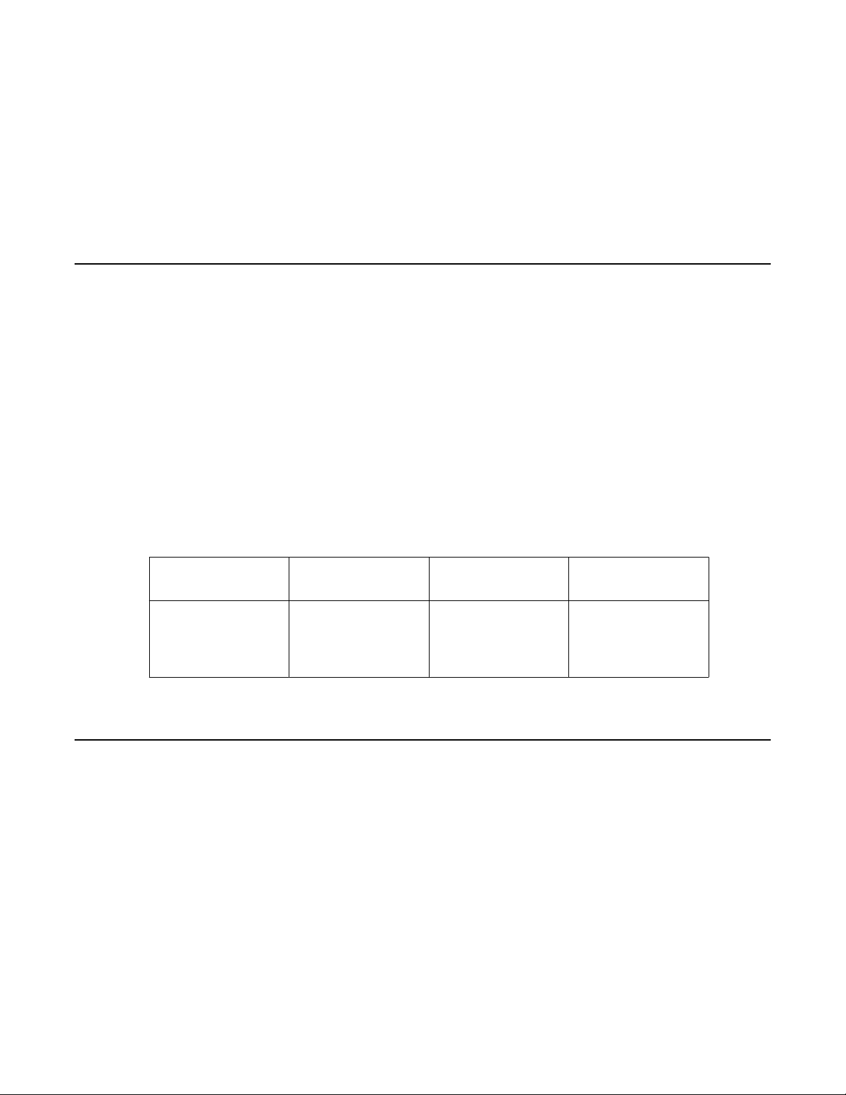
Required skills and knowledge
The audience is expected to have some experience installing Avaya products and be able to
perform administration procedures. They must also have a basic understanding and working
knowledge of the following areas:
Operating systems in
general
Graphical and
command line
interfaces such as
Windows and Linux
TCP/IP SSH SIP
FTP and SFTP LAN/WAN Hostname/DNS
Overview of System Manager
System Manager is a central management system that delivers a set of shared management
services and a common console across multiple products. System Manager includes the
following shared management services categorized as follows:
• Under Users
- Administrators
Manage administrative users within Avaya Unified Communications Management.
- Groups & Roles
Administering Avaya Aura® Session Manager November 2010 13
Page 14

Getting started
Manage groups, roles and assign roles to users.
- Synchronize and Import
Synchronize users with the enterprise directory, import users from file.
- User Management
Manage users, public contact lists, shared user resources, system level presence
access control lists.
• Under Elements
- Application Management
Manage application instances and application certificates
- Communication Manager
Manage Communication Manager objects such as Call Center, Call Coverage,
Endpoints and others.
- Conferencing
Manage Conferencing Application Services.
- Inventory
Manage, discover, and navigate to elements, update element software.
- Messaging
Manage Messaging System objects.
- Presence
Manage Presence based configuration properties, classes and access levels.
- Routing
Configure network configuration using Network Routing Policy.
- SIP AS 8.1
SIP AS Management Console
- Session Manager
Session Manager Management Console.
• Under Services
- Backup and Restore
Backup and restore System Manager database.
- Configurations
Manage system wide configurations.
14 Administering Avaya Aura® Session Manager November 2010
Comments? infodev@avaya.com
Page 15

Log on to System Manager
- Events
Manage alarms, view and harvest logs generated by System Manager and other
components of System Manager.
- Licenses
View and configure licenses for individual components of Avaya Aura Unified
Communication System.
- Replication
Track data replication nodes, repair replication nodes.
- Scheduler
Schedule, track, cancel, update and delete jobs.
- Security
Manage Security Certificates.
- Templates
Manage Templates for Communication Manager and Messaging System objects.
System Manager Common Console is the management interface for Session Manager. You
must log on to the System Manager Common Console to perform any administration or
configuration.
Log on to System Manager
Logging on to System Manager Web interface
The System Manager Web interface is the main interface of Avaya Aura System Manager . You
must log on to the System Manager Web console before you can perform any tasks.
Before you begin
A user account to log on to the System Manager Web interface. If you do not have a user
account, contact your system administrator to create your account.
Procedure
1. On the browser, open the System Manager URL (https://<SERVER_NAME>/
SMGR).
2. In the User ID field, enter the user name.
Administering Avaya Aura® Session Manager November 2010 15
Page 16

Getting started
3. In the Password field, enter the password.
4. Click Log On.
If your user name and password:
• Match an authorized System Manager user account, the System Manager
home page appears with the System Manager version_number. The System
Manager home page displays a navigation menu. This menu provides access
to shared services with which you can perform various operations supported
by System Manager. The tasks you can perform depends on your user role.
• If you enter incorrect login credentials on the System Manager login page,
System Manager displays an error message and prompts you to re-enter the
user name and password so that you can log in again.
Login information for users with user name admin
This login information applies only to users with log-on name admin.
• When you log on to System Manager for the first time after a fresh installation or an
upgrade, enter admin123 as the default password.
• After you log on, the system displays the Forced Change Password page. There is no
Cancel button on this page. You must change your password when you log on using the
default password.
• If you access System Manager through IP address, and you log on as “admin” for the first
time, you must use the Change Password link to change the password manually.
Y our password should contain a combination of alphanumeric and special characters. To know
more about the password strength policy, see
page 17.
Note:
In System Manager 6.1, you require two separate administrator user IDs for managing
System Manager and UCM. Users with the log-on name admin can manage both using the
same ID.
Password strength policy enforcement on
16 Administering Avaya Aura® Session Manager November 2010
Comments? infodev@avaya.com
Page 17
Password and security policies for users with username admin
Password and security policies for users with username
admin
Password aging policy enforcement
Note:
All password policies are applicable ONLY for users with the log-on name “admin”.
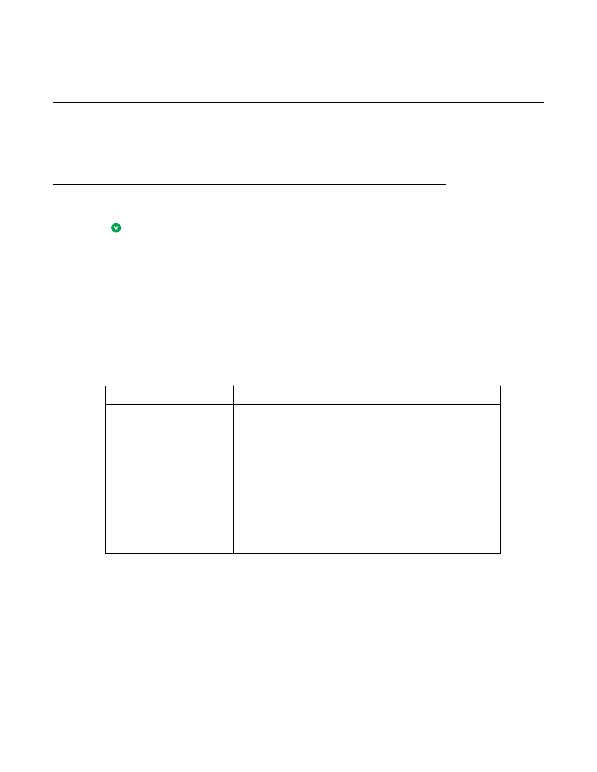
The password aging policy has the following time-based password thresholds that the network
administrator can configure as the number of days:
• Minimum password age
• Password expiration warning
• Password expiration
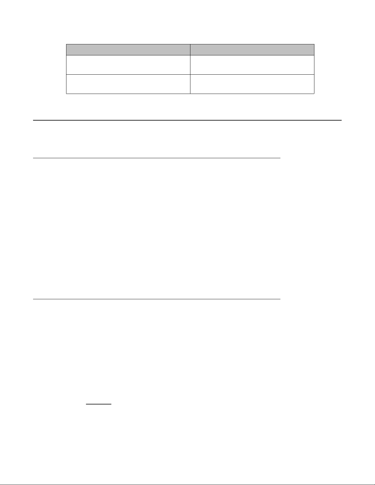
The following table describes what occurs when a user logs on to System Manager when the
password aging policy thresholds expire.
Password threshold What occurs when the threshold expires
Minimum password age You cannot change the password until the minimum
password age has been reached. For example, you cannot
change the password for three days after the last change was
made.
Password expiration
warning
Password expiration period You are forced to change the password after the threshold for
You receive a password expiration warning when the
password is about to expire and before the password
expires.
the password expires and before the threshold to disable the
account. The password is locked until it is reset by the
network administrator.
Password strength policy enforcement
Passwords must contain a combination of alphanumeric and special characters as defined by
the network administrator. The password strength policy enforces the following constraints:
Administering Avaya Aura® Session Manager November 2010 17
Page 18

Getting started
• Passwords must have a total character length from 6 to 25. Default is eight.
• Passwords are not required to have a minimum character type; however, the default is
one lower- and upper case character, one numeric character, and one special character,
such as exclamation mark (!). The sum cannot exceed the minimum total length.
After you enable the password strength policy, ensure that the following standards are met:
• Password must not have a character repeated more than twice consecutively.
• Passwords must not be your user ID, in forward or reverse order.
If a password does not contain the required parameters for password requirements, the system
rejects the password.
Note:
You can disable the password strength policy.
Password history policy enforcement
The password history policy verifies that a password is new. The previous blocked passwords
can range from 1 to 99. The default is six.
Password lockout policy enforcement
The lockout policy provides a limit for the number of attempts to access System Manager. The
user is locked out of System Manager when the specified number of logon attempts is reached.
By default, the user is locked out for two minutes after five failed attempts if the consecutive
attempts occur within a ten-minute period.
Inactive session termination policy
By default, the system suspends a user session after 30 minutes of inactivity . A user must log
on to System Manager again when this occurs.
Logon warning banner
System Manager provides the text for the logon warning banner that a network administrator
can change.
18 Administering Avaya Aura® Session Manager November 2010
Comments? infodev@avaya.com
Page 19

Editing password policies
About this task
Administrators can edit the password settings through this procedure.
Procedure
1. On the System Manager console, under Services, click UCM Services.
2. Click Security > Policies in the left navigation pane.
3. In the Password Policy section, click Edit.
4. Edit the required fields on the Password Policy page.
5. Click Save.
Click Cancel to undo your changes and return to the previous page.
Important:
An invalid logon message appears for the following scenarios:
Password and security policies for users with username admin
• A logon attempt is made on a disabled account
• The password is invalid.
• The maximum number of logon attempts is reached.
• The password is expired.
For each scenario, the system responds with a message that invalid logon
credentials were used. You must contact the network administrator for additional
information.
Related topics:
Password policies field descriptions on page 20
Editing Session Properties
Procedure
1. On the System Manager console, under Services, click UCM Services.
2. Click Security > Policies in the left navigation pane.
3. On the Policies page, in the Session Properties section, click Edit.
4. On the Session Properties page, edit the required fields.
Administering Avaya Aura® Session Manager November 2010 19
Page 20

Getting started
5. Click Save.
Related topics:
Session Properties field descriptions on page 22
Security settings
System Manager provides a customizable logon banner that appears when a user logs on to
the system. The customizable banner is intended for use by customers with security policies
that require network equipment to display a specific message to users when they log on.
Editing the login warning banner
Procedure
1. On the System Manager console, under Services, click UCM Services.
2. Click Security > Policies in the left navigation pane.
3. Click Security > Policies in the left navigation pane.
4. On the Policies page, in the Security Settings section, click Edit.
5. On the Security Settings page, edit the text as required in the Login Warning Banner
text area.
Note:
The maximum number of characters allowed is 2500.
6. Click Save.
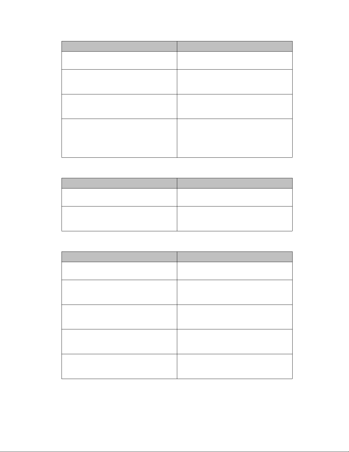
Password policies field descriptions
This page is applicable only for users with the user name “admin”.
Aging section
Name
Enforce password aging policies Select this check box if you want to enforce
20 Administering Avaya Aura® Session Manager November 2010
Comments? infodev@avaya.com
Description
the aging policies.
Page 21
Password and security policies for users with username admin
Name Description
Enable expired password change Select this check box if you want to allow
users to change password after it expires.
Expiration period Specifies the maximum allowable days to
maintain the password. Default value is 90.
You can enter values from 1 to 365.
Expiration warning Sends a warning to the user if the password
is about to expire. You can type in any value
from 1 to 15. The default value is 7.
Minimum age Minimum allowable days for password age.
You can type in a number from 0 to 7. The
default value is 3. Ensure that the number for
the expiration period is greater than the
minimum password age number.
History section
Name Description
History Select this check box to enforce policies
against previously used passwords.
Previous passwords blocked The number of passwords maintained in the
history. You cannot reset your password to
these values. The default value is 6.
Strength section
Name
Strength Select this check box to enforce password
Minimum Total Length Minimum number of characters required for
Minimum by character Type: Lower case Minimum number of lower case characters
Minimum by character Type: Upper case Minimum number of upper case characters
Description
content standards.
the password. The default value is 8. Y ou can
set the value from 6 to 25.
required in the password. Default value is
1.
required in the password. Default value is
1.
Minimum by character Type: Numeric
case
Administering Avaya Aura® Session Manager November 2010 21
Minimum number of numeric characters
required in the password. Default value is
1.
Page 22
Getting started
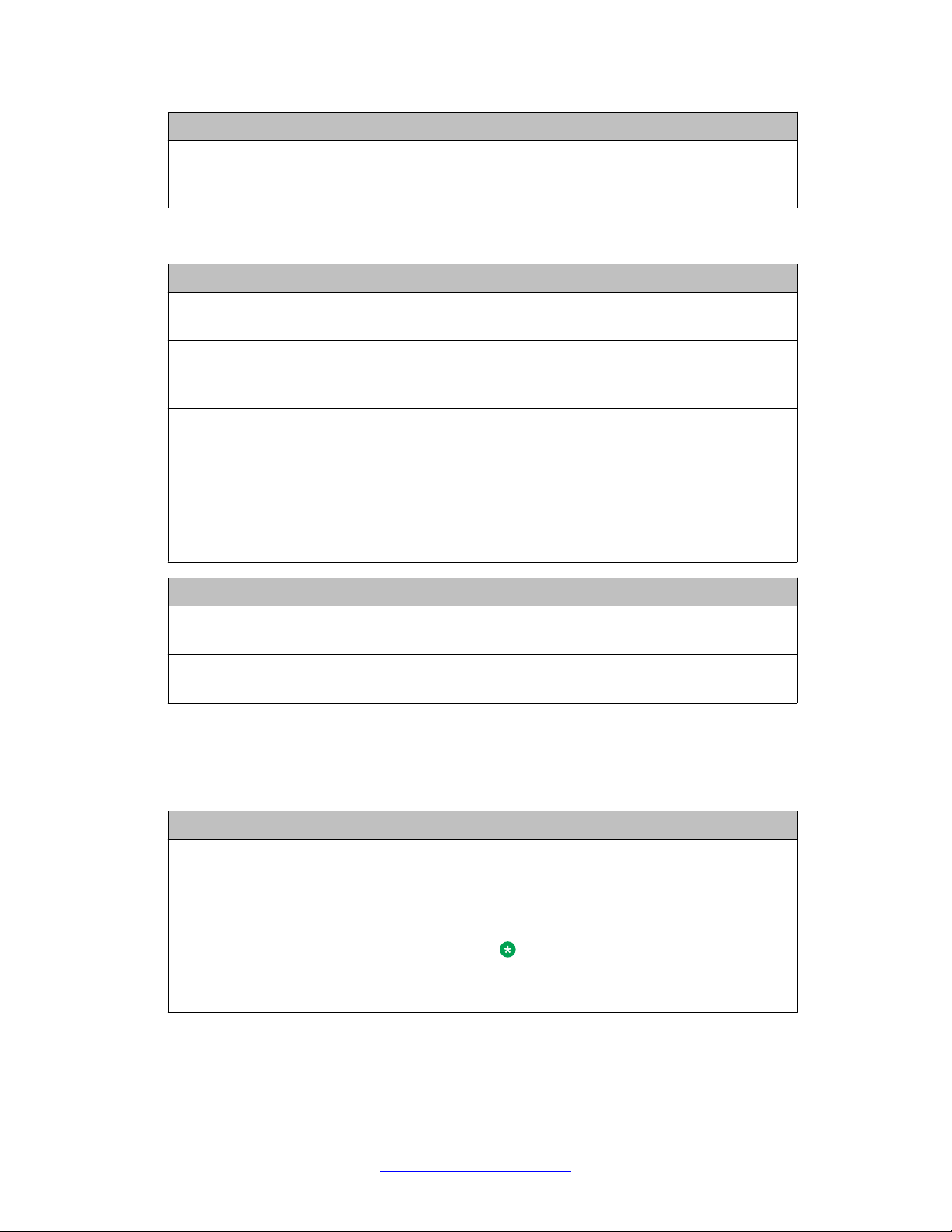
Lockout section
Name Description
Minimum by character T ype: Special case Minimum number of special characters
required in the password. Default value is
1.
Name Description
Lockout Select this check box if you want to enforce
lockout after failed login attempts.
Consecutive Invalid Login Attempts Number of failed attempts before lockout.
You can set values from 1 to 20 attempts.
Default value is 3.
Interval for Consecutive Invalid Login
Attempts
Lockout Time Number of minutes the account is locked
Button Description
Save Saves all your entries in the Edit Password
Cancel Cancels your changes and takes you back to
Time interval in minutes between invalid
login attempts. You can set values from 0 to
120 minutes. Default value is 10 minutes.
after invalid login attempts. You can set
values from 0 to 120 minutes. Default value
is 2 minutes.
Policies page.
the previous page.
Session Properties field descriptions
Name
Maximum Session Time Maximum time a session can remain active.
Description
Type any value from 0 to 1440.
Maximum Idle Time Maximum time a session can remain idle.
Type any value between 0 to 1440.
Note:
This value cannot exceed Maximum
Session Time.
22 Administering Avaya Aura® Session Manager November 2010
Comments? infodev@avaya.com
Page 23
Button Description
Save Saves your entries in the Session Properties
Cancel Cancels your entries and takes you to the
SIP Application Server
Overview of SIP Application Server
The SIP Application Server (SIP A/S) is a scalable, highly available and high-performance
server for the development and deployment of real-time, multimedia, presence-enabled IP
communications applications. The SIP Application Server is composed of the following
components:
SIP Application Server
page.
previous page.
• Service Director — This performs decision-based routing of incoming SIP messages to
the Service Host for processing.
• Service Host — This hosts applications and interacting with external entities. It processes
SIP messages received from Service Directors and other SIP end points.
• Management Server — This hosts the SIP Application Server management console for
monitoring component statistics.
Session Manager software is an application that runs on the SIP A/S.
Starting the SIP Application Server management console
Procedure
1. On the System Manager console, under Elements, click SIP AS 8.1.
2. On the SIP A/S Connection Details page, enter the host name and administration
port of the Management Access Point Hostname / IP of the Session Manager.
The default port as 5759 is filled in. This should not be changed.
3. Click Connect.
For more information, see the Avaya Aura® System Manager online Help system.
Administering Avaya Aura® Session Manager November 2010 23
Page 24
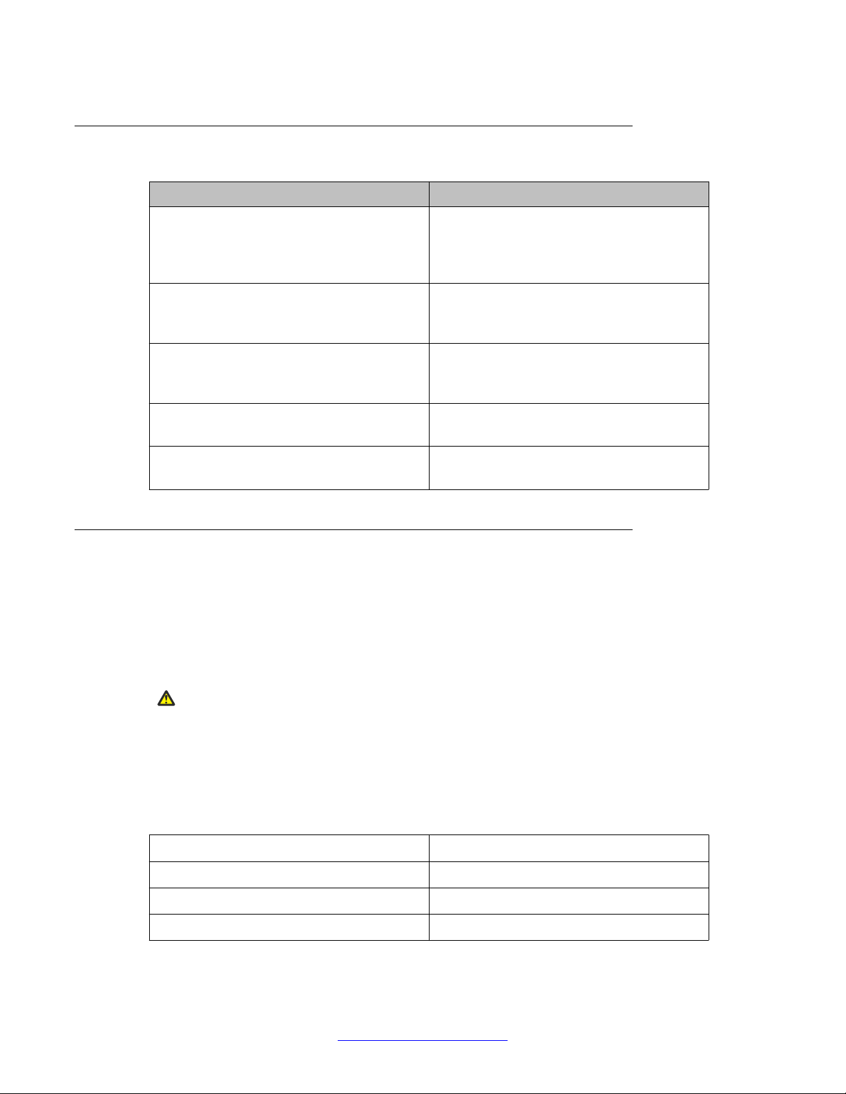
Getting started
SIP A/S Connection Details field descriptions
Name Description
Primary Hostname The name of the machine hosting the primary
Management Server of the SIP Application
Server cluster to which you are connecting.
This is mandatory.
Primary Port The administration port of the primary
Management Server.
This is mandatory.
Backup Hostname The name of the machine hosting the backup
Management Server of the SIP Application
Server cluster to which you are connecting.
Backup Port The administration port of the backup
Management Server.
Connect Connect to the SIP Application Server
cluster.
About SIP Application Server Management Console
The SIP Application Server Management Console enables viewing of the following details:
• System Status
• Service Director statistics
• Service Host statistics
Warning:
Changing the existing configurations using the SIP Application Server Management Console
voids your product warranty.
The System Status page of the SIP Application Server Management Console shows a graphic
representation of the SIP Application Server cluster . A status icon next to each cluster element
node specifies the operational status of that element, as defined in the following table.
Status Icon Cluster element status
Green check symbol The cluster element is running.
Red cross mark symbol The cluster element is in an error state.
Yellow triangle symbol Other configuration error.
24 Administering Avaya Aura® Session Manager November 2010
Comments? infodev@avaya.com
Page 25
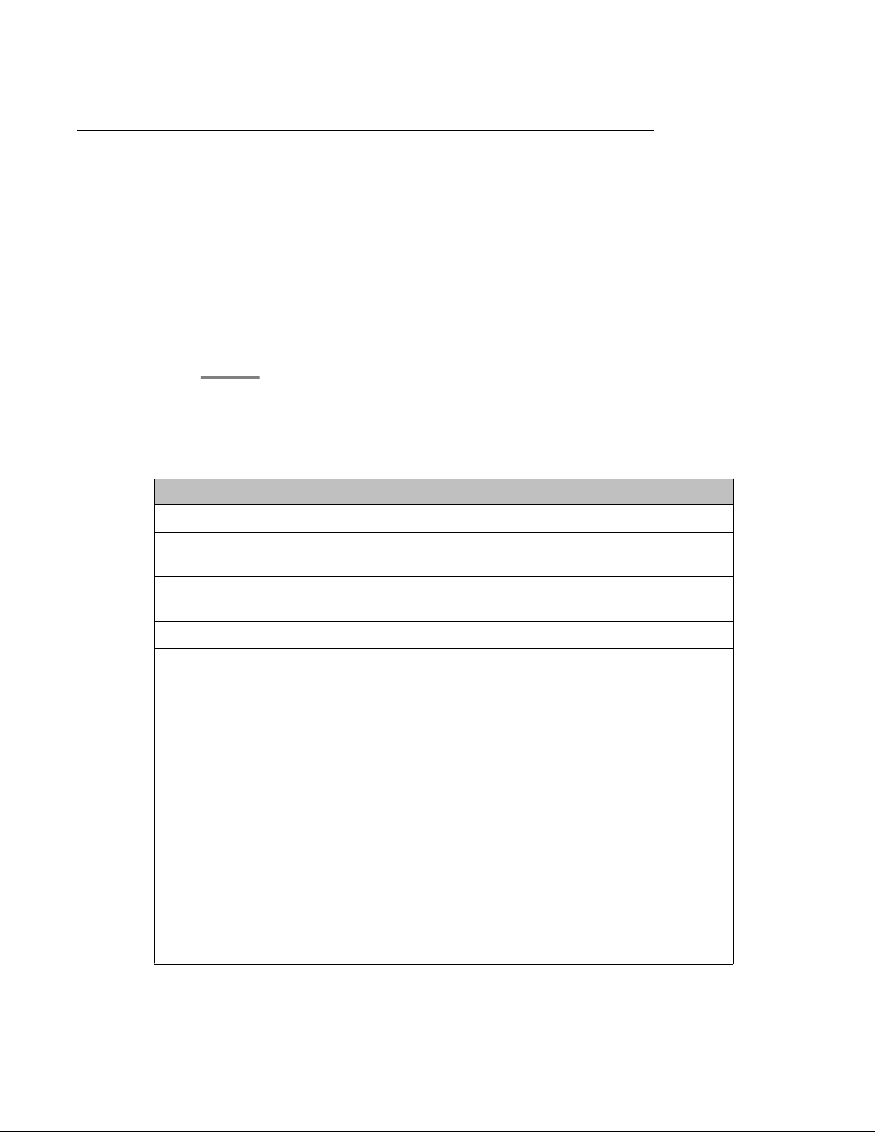
Viewing Service Director Statistics
Procedure
1. On the SIP Application Server Management Console, click Monitoring > Statistics
> Service Directors.
The Statistics: Service Directors page opens showing details of the listed Service
Director.
2. Select the Service Director instance and click View.
The Service Director Statistics page opens where you can view statistics for the
selected Service Director instance.
Statistics: Service Directors field descriptions
SIP Application Server
Name Description
Id A number assigned to the Service Director.
Host Name The host name or IP address of the Service
Director.
Administrator Port The administration port number of the
Service Director.
Version The version of SIP Application Server.
Status The operational state of each the Service
Director.
Options include:
• RUNNING: The Service Director has been
started and is operating normally.
• DOWN: The Service Director is
unavailable.
• UNKNOWN: The operational status of the
Service Director cannot be determined.
• RESTARTING: The Service Director is
rebooting from a previously up state and
will soon become available.
• STARTING: The Service Director is
starting up from a down state and will soon
become available.
Administering Avaya Aura® Session Manager November 2010 25
Page 26
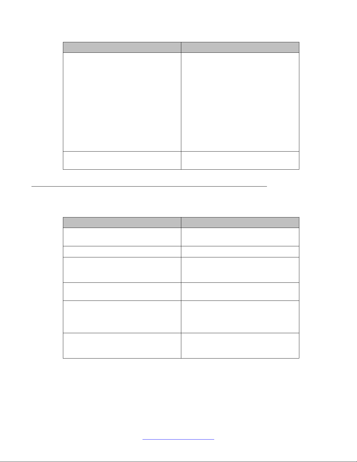
Getting started
Name Description
• TESTING: The Service Director is in
testing mode.
• HALTED: The Service Director is
stopped.
• HALTING: The Service Director is
stopping.
• DISABLED: The Service Director is
disabled but can still receive
configuration.
• BOOTERROR: The Service Director has
encountered an error during start-up.
Restart Req? Indicates whether the Service Director
requires a restart.
Service Director Statistics field descriptions
Some of the important fields are listed below:
Name
Status The operational state of the Service
Up Time The time since Service Director start-up.
Received Request Count The number of SIP request messages
Sent Response Count The number of SIP response messages sent
Dropped Requests Count The number of requests not forwarded to a
Bounced Requests Count The number of 503 responses sent as a
Description
Director.
received by the Service Director since startup.
by the Service Director since start-up.
Service Host as a result of traffic throttling
initiated by Self A wareness and Preservation
rules.
result of traffic throttling initiated by Self
Awareness and Preservation rules.
26 Administering Avaya Aura® Session Manager November 2010
Comments? infodev@avaya.com
Page 27
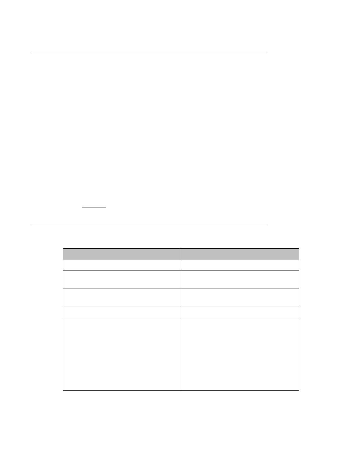
Viewing Service Host Instance Statistics
Procedure
1. On the SIP Application Server Management Console, click Monitoring > Statistics
> Service Hosts.
The Statistics: Service Hosts page opens showing the list of Service Hosts.
2. In the section Service Host Instance Statistics, select a Service Host instance and
click View.
The Service Host Statistics page opens where you can view statistics for the
selected Service Host instance.
3. In the section View Statistics from Last 24 Hours, select a statistic record to view
and click View Data.
The Statistics Detail View page opens where you can view the 24 hour details for
the selected statistics.
4. On the Statistics Detail View page, click Export CSV to export the data into commaseparated value format for display in a spreadsheet application.
SIP Application Server
Statistics: Service Hosts field descriptions
Name
Id A number assigned to each Service Host.
Host Name The host name or IP address of the Service
Administrator Port The administration port number of the
Version The version of SIP Application Server.
Status The operational state of each Service Host.
Description
Host.
Service Host.
Options include:
• RUNNING: The Service Host has been
started and is operating normally.
• DOWN: The Service Host is unavailable.
• UNKNOWN: The operational status of the
Service Host cannot be determined for
some reason.
Administering Avaya Aura® Session Manager November 2010 27
Page 28
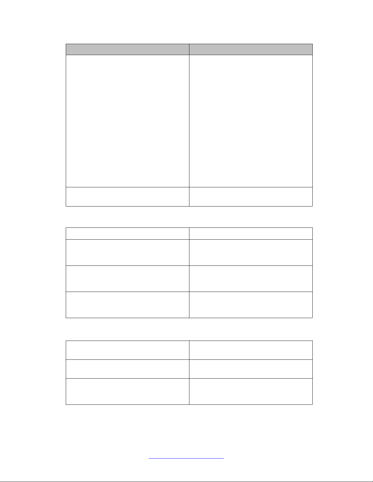
Getting started
Name Description
• RESTARTING: The Service Host is
rebooting from a previously up state and
will soon become available.
• ST ARTING: The Service Host is starting up
from a down state and will soon become
available.
• TESTING: The Service Host is in testing
mode.
• HALTED: The Service Host is stopped.
• HALTING: The Service Host is stopping.
• DISABLED: The Service Host is disabled
but can still receive configuration.
• BOOTERROR: The Service Host has
encountered an error during start-up.
Restart Req? Indicates whether the Service Host requires
a restart.
View Statistics from Last 24 Hours
Statistic The statistic being monitored.
Peak (Cross-Cluster Total) The highest value observed for this attribute
from totalling the attribute values across all
Service Hosts.
Peak (Individual) The highest individual value observed for this
attribute over the last 24 hours, amongst all
individual Service Hosts.
Average The current average of the attribute's values
totalled across all Service Hosts over the last
24 hours.
Some of the important fields are listed below:
CPU Usage Percentage The percentage CPU usage on the Service
Host installation platform.
Total number of requests received Total number of SIP message requests
received by the Service Host.
Active SIP Transactions The number of new active transactions
currently being processed by the Service
Host.
28 Administering Avaya Aura® Session Manager November 2010
Comments? infodev@avaya.com
Page 29
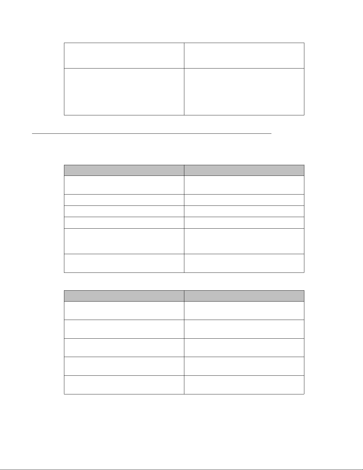
Free Physical Memory (Mb) The amount of free physical memory
available on the Service Host hardware
platform.
Container Sip Application Sessions The number of SIP application sessions
currently being processed by the Service
Host. This equals the sum of the number of
sessions which represent subscriptions from
endpoints and the number of currently active
calls handled by the Session Manager.
Service Host Statistics field descriptions
Some of the important fields are listed below:
Name Description
SIP Protocol Version The SIP protocol version used by the Service
Host.
SIP Application Server
Status The operational state of the Service Host.
Up Time The time since Service Host initialization.
Running The running state of the Service Host.
SIP Application Sessions The number of SIP Application Sessions
currently being processed by the Service
Host.
Active SIP Application Sessions The number of SIP transactions currently
being processed by the Service Host.
Summary Statistics
Name
SIP Initial Requests Per Second In SIP initial requests per second received by
SIP Initial Requests Per Second Out SIP initial requests per second sent from the
Unsupported URI Count The total number of unsupported URIs that
Total Requests In The total number of SIP requests received by
Description
the Service Host since last reported.
Service Host since last reported.
have sent SIP requests to the Service Host.
the Service Host.
Total Requests Out The total number of SIP requests sent by the
Service Host.
Administering Avaya Aura® Session Manager November 2010 29
Page 30
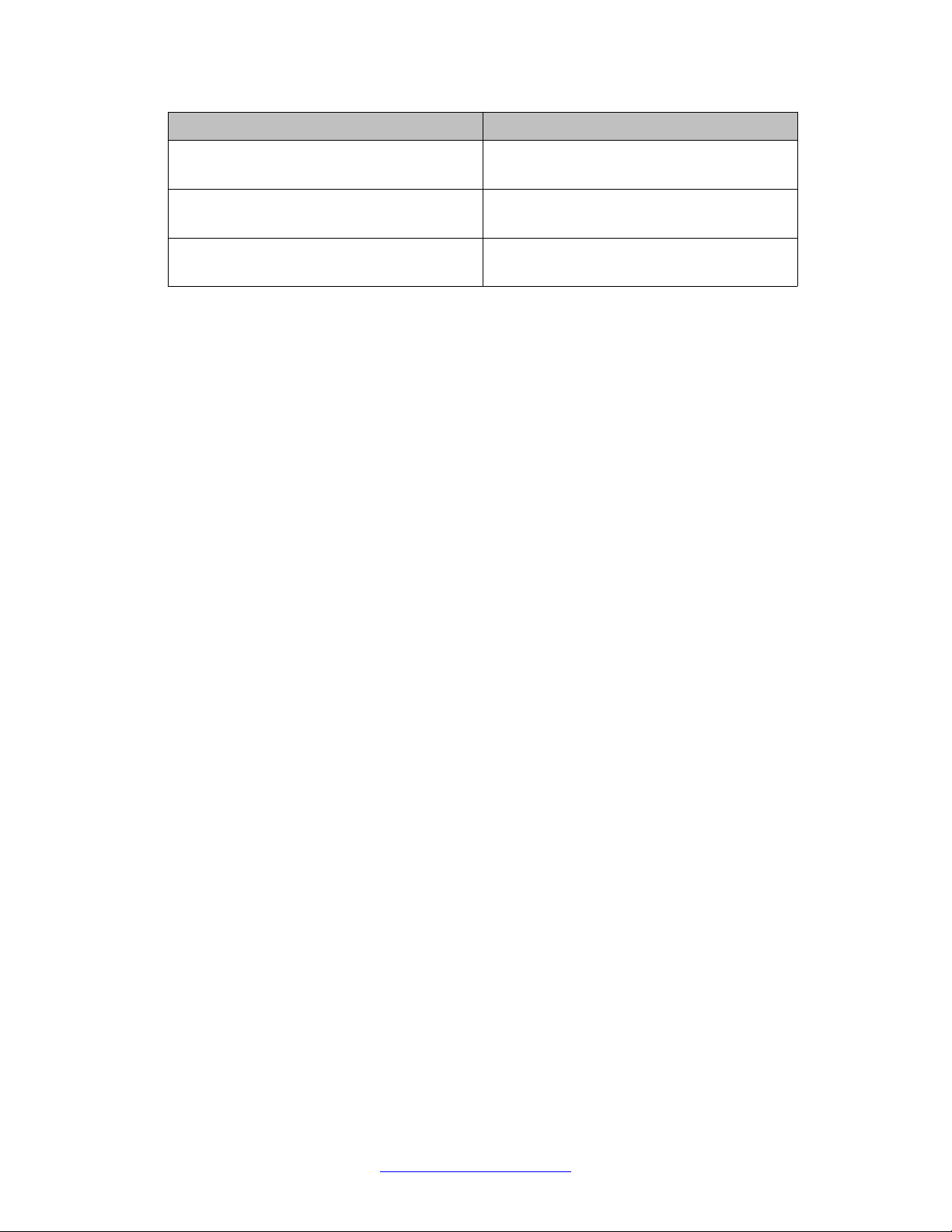
Getting started
Name Description
Total Responses In The total number of SIP responses received
by the Service Host.
Total Responses Out The total number of SIP responses sent by
the Service Host.
Transaction Quantity The total number of transactions that have
taken place through the Service Host.
30 Administering Avaya Aura® Session Manager November 2010
Comments? infodev@avaya.com
Page 31

Chapter 2: Synchronizing Communication
Manager and messaging data
with System Manager
Introduction
This chapter explains how to use Communication System Manager feature to synchronize
Communication Manager station data to the System Manager database. The system
automatically connects to System Manager and Communication Manager in the core and
synchronizes provisioning data in the System Manager database with each managed
Communication Manager system. You can synchronize the endpoint data in a scheduled and
incremental basis as follows:
1. Administration of each Communication Manager as an entity or application
instance.
2. Initialization of the synchronization of Communication Manager and messaging
data with System Manager.
Creating a Communication Manager instance
Procedure
1. On the System Manager console, under Elements, click Inventory.
2. Click Inventory > Manage Elements in the left navigation pane.
3. On the Manage Elements page, click New and select a “CM” entity instance.
4. On the New CM Instance page, enter the appropriate details:
a. In the Node field, specify the management IP address for the Communication
Manager (this is the address used for SSH SAT login).
b. Select “default (none)” for the SNMP Attributes section
c. Under Attributes section, enter the SSH SAT login for the Login field and the
associated password in the Password field.
Administering Avaya Aura® Session Manager November 2010 31
Page 32

Synchronizing Communication Manager and messaging data with System Manager
5. Click Commit .
When you add an application entity through RTS (Runtime Topology Service), it in
turn starts a synchronization job in the background to bring all the relevant data from
the application instances to the Communication System Management database.
You can check the status of this synchronization job on the System Manager
console by accessing System Manager Data > Scheduler or in the log files on the
Communication System Management server.
Creating a messaging instance
Procedure
1. On the System Manager console, under Elements, click Inventory.
2. Click Inventory > Manage Elements in the left navigation pane.
3. On the Manage Elements page, click New and select a “Messaging” entity
instance.
4. On the New Messaging Instance page, enter the details as described below:
• The details (FQDN or IP address) in the Node field for a messaging instance
should correspond to that of MSS (Messaging Storage Server) and not MAS
(Messaging Application Server).
• Y ou have to add the System Manager or Communication System Management
server details in the Trusted Server list on the Messaging box (in Messaging
Administration / Trusted Servers screen), before adding the Messaging box in
the System Manager applications.
• The login credentials between the Messaging box trusted servers screen and
the Session Manager application, entity, or attributes for a Messaging type of
application have to match.
• The Trusted Server Name field on the Trusted Server page is mapped to the
Login field in the Attributes section. Similarly the Password field on the Trusted
Server page is mapped to the Password field in the Attributes section.
• You should set the LDAP Access Allowed field on the trusted server page to
yes, to allow LDAP access to this Messaging box from the trusted server that
you add.
5. Click Commit .
When you add an application entity through RTS (Runtime Topology Service), it in
turn starts a synchronization job in the background to bring all the relevant data from
the application instances to the Communication System Management database.
You can check the status of this synchronization job on the System Manager
32 Administering Avaya Aura® Session Manager November 2010
Comments? infodev@avaya.com
Page 33

console by accessing Scheduler under Services in the System Manager console
or the log files on the Communication System Management server.
Initializing Synchronization
Procedure
1. On the System Manager console, under Elements, click Inventory.
2. Click Synchronization > Communication System in the left navigation pane.
3. Select the Communication Managers you want to synchronize.
4. Select Initialize data for selected devices.
5. Click Now to perform the initializing synchronization or do one of the following:
• Click Schedule to perform the synchronization at a specified time.
Initializing Synchronization
• Click Cancel to cancel the synchronization.
Synchronizing Messaging Data
Procedure
1. On the System Manager console, under Elements, click Inventory.
2. Click Synchronization > Messaging Data in the left navigation pane.
3. Select the messaging systems you want to synchronize.
4. Click Now to perform the synchronization or do one of the following:
• Click Schedule to perform the synchronization at a specified time.
• Click Cancel to cancel the synchronization.
Manage Elements field descriptions
Use this page to view the create, edit, view, and delete instances of the application.
Administering Avaya Aura® Session Manager November 2010 33
Page 34

Synchronizing Communication Manager and messaging data with System Manager
Name Description
Name Displays the name of the application
instance.
Node Displays the node on which the application
runs.
Type Displays the type of the application to which
the instance belongs. You can view this field
only if you access the Manage Elements
page through the Inventory menu.
Version Displays the version of the application
instance. You can view this field only if you
access the Manage Elements page through
the Inventory menu .
Description Displays a brief description about the
application instance.
Button Description
View Opens the View Other Applications Instance
page. Use this page to view the details of the
selected application instance.
Edit Opens the Edit Other Applications Instance
page. Use this page to modify the information
of the instance.
New Opens the New Other Applications Instance
page. Use this page to create a new
application instance.
Delete Opens the Delete Other Applications
Instance Confirmation page. Use this page
to delete a selected application instance.
More Actions > Configure Trusted
Certificates
Opens the Trusted Certificates page. Use
this page to view, add and delete the trusted
certificates for the application instance.
More Actions > Configure Identity
Certificates
Opens the Identity Certificates page. Use
this page to view and replace the identity
certificates for the application instance.
More Actions > Import Opens the Import Applications page. Use
this page to bulk import application data from
a valid xml file.
Filter: Enable Displays fields under select columns that you
can use to set filter criteria. This is a toggle
button.
34 Administering Avaya Aura® Session Manager November 2010
Comments? infodev@avaya.com
Page 35

Button Description
Filter: Disable Hides the column filter fields. This is a toggle
button.
Filter: Apply Filters application instances based on the
filter criteria.
Select: All Selects all the application instances in the
table.
Select: None Clears the selection for the users that you
have selected.
Refresh Refreshes the application instance
information in the table.
Application Details field descriptions
Application Details field descriptions
Use this page to add and edit an application instance.
Application
Name
Name Displays the name of the application
Type Displays the type of the application to which
Description Displays a brief description about the
Node Displays the node on which you want to run
Description
instance.
the application instance belongs.
application instance.
the application instance.
Note:
The system displays this field when you
select Other from the Node field.
Port
Name
Description
Name Displays the name of the port.
Port Displays the port on which the application
instance is running.
Administering Avaya Aura® Session Manager November 2010 35
Page 36

Synchronizing Communication Manager and messaging data with System Manager
Name Description
Protocol Displays the protocol associated with the
corresponding port.
Description Displays a brief description about the port.
Button Description
New Displays fields in the Port section that you
can use to add a port.
Edit Displays fields in the Port section with port
information. You can modify the port details
in the port mode.
Delete Deletes the selected configured port.
Save Saves the port details.
Note:
The section displays this button only when
you click Add or Edit in the Port section.
Cancel Cancels the operation of creating or editing
an access point and hides the fields that you
use to enter or modify the port information.
Note:
The section displays this button only when
you click Add or Edit in the Port section.
Access Point
Name
Name Displays the name of the access point.
Access Point Type Displays the type of the access point.
Description
The options are:
• EMURL: Use this option to create a URL
type access point .
• WS: Use this option to create a Webservice
access point.
• GUI: Use this option to create any GUI
access point.
• Other
Protocol Displays the protocol that the application
instance supports to communicate with other
communication devices.
36 Administering Avaya Aura® Session Manager November 2010
Comments? infodev@avaya.com
Page 37

Application Details field descriptions
Name Description
Host Displays the name of the host on which the
application instance is running.
Port Displays the port on which the application
instance is running.
Order Displays the order in which the access points
are accessed.
Button Description
New Displays fields in the Access Point section
that you can use to add port details.
Edit Displays fields in the Access Point section
that allows you to modify the selected port
details.
Delete Deletes the selected access point.
These fields appear when you click Add or Edit in the Access Point section.
Name Description
Name Displays the name of the access point.
Access Point Type Displays the type of the access point.
The options are:
• EMURL: Use this option to create a URL
type access point .
• WS: Use this option to create a Webservice
access point.
• GUI: Use this option to create any GUI
access point.
• Other
Protocol Displays the protocol for communicating with
the application instance.
Host Displays the name of the host on which the
application instance is running.
Port Displays the port on which the application
instance is running.
Order Displays the order in which the access points
are accessed.
Button Description
Save Saves the access point details.
Administering Avaya Aura® Session Manager November 2010 37
Page 38

Synchronizing Communication Manager and messaging data with System Manager
Button Description
Note:
This button is visible only when you click
Add and Edit in the Access Point
section.
Cancel Cancels the operation of creating or editing
an access point and hides the fields that you
use to enter or modify the access point
information.
Note:
This button is available only when you
click Add and Edit in the Access Point
section.
Attributes
This section provides information about attributes fields that you can configure for the selected
application. This section appears only if the ApplicationType is defined to have Attributes
through EP metadata.
Name Description
Login Login name to be used for connecting to the
application instance.
Note:
craft, craft2, dadmin, inads, init,
rasaccess, sroot, and tsc are the
restricted logins when you configure a
Communication Manager system.
Note:
Do not use this login to connect to
Communication Manager from any other
application or to connect to the
Communication Manager SAT terminal
using CLI.
Password Password which authenticates the SSH/
Telnet login name on the application
instance. This field is not required for ASG
login.
Is SSH Connection Use this check box to specify whether the
SSH connection should be used to connect
to the application instance. By default this is
selected. If you clear the check box, the
connection with the application instance is
made using Telnet.
38 Administering Avaya Aura® Session Manager November 2010
Comments? infodev@avaya.com
Page 39

Application Details field descriptions
Name Description
Port The port on which the service provided by the
application instance is running. The default
SSH port is 5022.
Alternate IP Address Alternate IP address of the application
instance. This is the IP address of the
standby server in case of duplex servers.
RSA SSH Fingerprint (Primary IP) The RSA SSH key of the Communication
Manager Server. In case of Duplex servers,
RSA SSH Key is the key of the Active
server.
RSA SSH Fingerprint (Alternate IP) The DSA SSH Key of the CM Server used
only in case of Duplex servers. This is the key
of the Standby server.
Is ASG Enabled Use this check box to enable ASG. If you
select the Is ASG enabled check box, then
you should enter the ASG key. Password is
not required.
ASG Key The ASG key used to authenticate the ASG
login. You do not have to enter any value in
this field if non-ASG login is used.
Location Displays the location of the application
instance.
The following fields provides information about attributes related to messaging.
Name
Login Displays the name as given in the Trusted
Password Password for the login name as given in the
Confirm Password You should retype the password for
Messaging Type Displays the type of the Messaging box. The
Description
Server Name field of the Trusted Servers
page on the Messaging Box for this server.
Password field of the Trusted Servers page
on the Messaging Box for this server.
confirmation.
following are the types of messaging:
• MM: for Modular Messaging systems
• CMM: for Communication Manager
Embedded Messaging systems
Version Displays the version of the Messaging Box.
Supported versions are 5.0 and above.
Administering Avaya Aura® Session Manager November 2010 39
Page 40

Synchronizing Communication Manager and messaging data with System Manager
Name Description
Secured LDAP Connection Use this check box to specify whether
Secure LDAP connection is to be used.
Select this check box to use secure LDAP
connection, else LDAP will be used.
Port Displays the port on which the LDAP or
secure LDAP service provided by the
application instance is running. For LDAP the
port is 389 and for secure LDAP the port is
636.
Location Displays the location of the application
instance.
SNMP Attributes
You set some basic parameters for specific devices or a range of devices in the SNMP
Attributes section. You can choose either SNMP protocol V1 or V3. Based on your selection
of SNMP protocol, you can then set certain basic SNMP parameters.
Name Description
Version Specifies the SNMP protocol type.
Read Community Displays the read community of the device.
Only applicable for SNMP protocol V1.
Write Community Displays the write community of the device.
Only applicable for SNMP protocol V1.
Retries Displays the number of times an application
polls a device without receiving a response
before timing out.
Timeout Displays the number of milliseconds an
application polls a device without receiving a
response before timing out.
Device Type Specifies the type of the device
Assign Applications
Name
Name Displays the name of the application
Type Displays the type of application.
Description
instance.
Description Displays a brief description about the
application instance.
40 Administering Avaya Aura® Session Manager November 2010
Comments? infodev@avaya.com
Page 41

Application Details field descriptions
Button Description
Assign Applications Opens the Assign Applications page. Use
the page to assign an application instance to
another application instance.
Unassign Applications Removes an assigned application.
Button Description
Commit Creates or modifies an instance by saving
the instance information to the database.
Note:
This button is visible only when you click
New and Edit on the Application
Management page.
Cancel Closes the page without saving the
information and takes you back to the
Application Management page.
Administering Avaya Aura® Session Manager November 2010 41
Page 42

Synchronizing Communication Manager and messaging data with System Manager
42 Administering Avaya Aura® Session Manager November 2010
Comments? infodev@avaya.com
Page 43

Chapter 3: Managing Security
Introduction
Trust Management provisions certificates to applications enabling them to have a secure interelement communication. It provides Identity and Trusted (root) certificates with which mutually
authenticated TLS sessions can be established.
For administering third-party trusted certificates for Session Manager, a "Session Manager"
application needs to be added for a specific Session Manager or Branch Session Manager
instance. This application is administered with the “Management Access Point” IP address of
the Session Manager instance. Using the Trust Management service, you can perform the
following operations for the application instance:
• View trusted and identity certificates currently installed on the Session Manager server.
• Add and remove trusted certificates installed on the Session Manager server.
Note:
Adding, removing and replacing of certificates is not currently supported for either Identity
Certificates or for non-third party certificates that is the default certificates provided by A vaya
cannot be changed.
Setting SCEP enrollment password
About this task
You can use this functionality to generate the simple certificate enrollment password (SCEP)
for adopting products. The adopting products require the SCEP password to request
certificates from Trust Management.
Procedure
1. On the System Manager console, under Services, click Security.
2. Click Certificates > Enrollment Password in the left navigation pane.
3. On the Enrollment Password page, select the expiration of password in hours in the
Password expires in field.
Administering Avaya Aura® Session Manager November 2010 43
Page 44

Managing Security
4. Click Generate.
The password field displays the generated password.
5. Click Commit.
Note:
When you click Commit, the time displayed next to the Time remaining label is
updated by the value selected in the Password expires in field.
Adding a Session Manager application
Procedure
1. On the System Manager console, under Elements, click Inventory.
2. Click Inventory > Manage Elements in the left navigation pane.
3. On the Manage Elements page, click New and select a “Session Manager” entity
instance.
4. On the New Session Manager Instance page, enter the following details:
a. Under Application section, enter a name in the Name field for this Session
Manager.
b. Enter the Management Access Point IP address of this Session Manager in the
Node field, which is same as the value entered for Session Manager instance
during Session Manager administration.
c. Under Access Point section, select the pre-populated Access Point in the table
and click Edit. Enter name in the Name field, Management Access Point IP
address in the Host field and any text in the URI field. The default values for
the Protocol field is “jnp” and Port field is 1299.
Y ou need not change other default values and specifically for protocol and port,
the default values should not be changed.
d. Click Save.
5. Click Commit .
Viewing trusted certificates
Before you begin
You must have permission to view certificates of an application instance.
44 Administering Avaya Aura® Session Manager November 2010
Comments? infodev@avaya.com
Page 45

Procedure
1. On the System Manager console, under Elements, click Inventory.
2. Click Inventory > Manage Elements in the left navigation pane.
3. On the Manage Elements page , select a Session Manager instance and click More
Actions > Configure Trusted Certificates.
4. On the Trusted Certificates page, click View.
Result
The View Trust Certificate page displays the details of the selected certificate.
Adding trusted certificates
About this task
Adding trusted certificates
You need to import the certificates that you want to add as trusted certificate in the trust store
of the application. The following are the four methods of importing a trusted certificate in the
trust store for an application instance:
1. Import from existing
2. Import from file
3. Import as PEM Certificate
4. Import using TLS
You can add a trusted certificate from a list of an existing certificates, a file, a remote location
using TLS connection and by copying the content from a PEM file.
Procedure
1. On the System Manager console, under Elements, click Inventory.
2. Click Inventory > Manage Elements in the left navigation pane.
3. On the Manage Elements page , select a Session Manager instance and click More
Actions > Configure Trusted Certificates.
4. On the Trusted Certificates page, click Add.
5. On the Add Trusted Certificate page, select store type from the Store Type field
as SM_SECURITY_MODULE and perform one of the following steps:
• To import certificates from existing certificates:
i. Click Import from existing .
ii. Select the certificate from the Global Trusted Certificate section.
Administering Avaya Aura® Session Manager November 2010 45
Page 46

Managing Security
iii. Click Commit.
• To import certificates from a file (in .cer format):
i. Click Import from file .
ii. Enter the name of the file. You can also click Browse to select a
file.
iii. Click Retrieve Certificate.
iv. Click Commit.
• To import certificates in the PEM format:
i. Locate the PEM certificate.
ii. Open the certificate in the Notepad application.
iii. Select all the contents in the file.
iv. Perform a copy operation.
v. Click Import as PEM Certificate .
vi. Perform a paste operation in the box provided at the bottom of the
page.
Note:
You may include the start and end tags: -----BEGIN
CERTIFICATE-----" and "-----END CERTIFICATE----.
vii. Click Commit.
• To import using TLS:
i. Click Import using TLS .
ii. Enter the IP Address of the computer in the IP Address field.
iii. Enter the port of the computer in the Port field.
iv. Click Retrieve Certificate.
v. Click Commit.
Exporting the Session Manager Certificate
Procedure
1. On the System Manager console, under Elements, click Inventory.
2. Click Inventory > Manage Elements in the left navigation pane.
46 Administering Avaya Aura® Session Manager November 2010
Comments? infodev@avaya.com
Page 47

3. On the Manage Elements page , select a Session Manager instance and click More
Actions > Configure Trusted Certificates.
4. Select SM_SECURITY_MODULE and click Export to save it.
Removing trusted certificates
Procedure
1. On the System Manager console, under Elements, click Inventory.
2. Click Inventory > Manage Elements in the left navigation pane.
3. On the Manage Elements page , select a Session Manager instance and click More
Actions > Configure Trusted Certificates.
4. On the Trusted Certificates page, select the certificates and click Remove.
Removing trusted certificates
Result
Trust Management removes the certificates from the list of trusted certificates for the Session
Manager instance instance.
Refreshing CA Certificate List
About this task
T o enable the security module to refresh the list of CA certificates and include the newly added
ones, do the following steps:
Procedure
1. On the System Manager console, under Elements, click Session Manager.
2. Click System Status > Security Module Status.
3. Select the Session Manager instance and click Update Installed Certificates.
4. Click Confirm.
Administering Avaya Aura® Session Manager November 2010 47
Page 48

Managing Security
Viewing identity certificates
Procedure
1. On the System Manager console, under Elements, click Inventory.
2. Click Inventory > Manage Elements in the left navigation pane.
3. On the Manage Elements page , select a Session Manager instance and click More
Actions > Configure Identity Certificates.
4. On the Identity Certificates page, click View.
Result
The Identity Certificate page displays the identity certificates.
Enrollment Password field descriptions
Use this page to generate a simple certificate enrollment password (SCEP).
Name
Existing Password The current simple certificate enrollment
Time Remaining Specifies the time in hours and minutes
Password expires in Specifies the duration in hours for which the
Password The password that the external SCEP clients
Button Description
Generate Generates a random password.
Commit Updates the Existing Password and Time
Description
password (SCEP) that the external SCEP
clients use to request certificates.
remaining for expiration of the current
password.
existing password is valid.
use to request a certificate. Trust Manager
generates this password when you click
Generate.
Remaining fields.
48 Administering Avaya Aura® Session Manager November 2010
Comments? infodev@avaya.com
Page 49

Manage Elements field descriptions
Use this page to view the create, edit, view, and delete instances of the application.
Name Description
Name Displays the name of the application
instance.
Node Displays the node on which the application
runs.
Type Displays the type of the application to which
the instance belongs. You can view this field
only if you access the Manage Elements
page through the Inventory menu.
Version Displays the version of the application
instance. You can view this field only if you
access the Manage Elements page through
the Inventory menu .
Manage Elements field descriptions
Description Displays a brief description about the
application instance.
Button Description
View Opens the View Other Applications Instance
page. Use this page to view the details of the
selected application instance.
Edit Opens the Edit Other Applications Instance
page. Use this page to modify the information
of the instance.
New Opens the New Other Applications Instance
page. Use this page to create a new
application instance.
Delete Opens the Delete Other Applications
Instance Confirmation page. Use this page
to delete a selected application instance.
More Actions > Configure Trusted
Certificates
More Actions > Configure Identity
Certificates
Opens the Trusted Certificates page. Use
this page to view, add and delete the trusted
certificates for the application instance.
Opens the Identity Certificates page. Use
this page to view and replace the identity
certificates for the application instance.
Administering Avaya Aura® Session Manager November 2010 49
Page 50

Managing Security
Button Description
More Actions > Import Opens the Import Applications page. Use
Filter: Enable Displays fields under select columns that you
Filter: Disable Hides the column filter fields. This is a toggle
Filter: Apply Filters application instances based on the
Select: All Selects all the application instances in the
Select: None Clears the selection for the users that you
Refresh Refreshes the application instance
this page to bulk import application data from
a valid xml file.
can use to set filter criteria. This is a toggle
button.
button.
filter criteria.
table.
have selected.
information in the table.
Application Details field descriptions
Use this page to add and edit an application instance.
Application
Name
Name Displays the name of the application
Type Displays the type of the application to which
Description Displays a brief description about the
Node Displays the node on which you want to run
Description
instance.
the application instance belongs.
application instance.
the application instance.
Note:
The system displays this field when you
select Other from the Node field.
50 Administering Avaya Aura® Session Manager November 2010
Comments? infodev@avaya.com
Page 51

Application Details field descriptions
Port
Name Description
Name Displays the name of the port.
Port Displays the port on which the application
instance is running.
Protocol Displays the protocol associated with the
corresponding port.
Description Displays a brief description about the port.
Button Description
New Displays fields in the Port section that you
can use to add a port.
Edit Displays fields in the Port section with port
information. You can modify the port details
in the port mode.
Delete Deletes the selected configured port.
Save Saves the port details.
Note:
The section displays this button only when
you click Add or Edit in the Port section.
Cancel Cancels the operation of creating or editing
an access point and hides the fields that you
use to enter or modify the port information.
Note:
The section displays this button only when
you click Add or Edit in the Port section.
Access Point
Name
Name Displays the name of the access point.
Access Point Type Displays the type of the access point.
Description
The options are:
• EMURL: Use this option to create a URL
type access point .
• WS: Use this option to create a Webservice
access point.
Administering Avaya Aura® Session Manager November 2010 51
Page 52

Managing Security
Name Description
Protocol Displays the protocol that the application
Host Displays the name of the host on which the
Port Displays the port on which the application
Order Displays the order in which the access points
Button Description
New Displays fields in the Access Point section
• GUI: Use this option to create any GUI
access point.
• Other
instance supports to communicate with other
communication devices.
application instance is running.
instance is running.
are accessed.
that you can use to add port details.
Edit Displays fields in the Access Point section
that allows you to modify the selected port
details.
Delete Deletes the selected access point.
These fields appear when you click Add or Edit in the Access Point section.
Name
Name Displays the name of the access point.
Access Point Type Displays the type of the access point.
Protocol Displays the protocol for communicating with
Description
The options are:
• EMURL: Use this option to create a URL
type access point .
• WS: Use this option to create a Webservice
access point.
• GUI: Use this option to create any GUI
access point.
• Other
the application instance.
Host Displays the name of the host on which the
application instance is running.
52 Administering Avaya Aura® Session Manager November 2010
Comments? infodev@avaya.com
Page 53

Application Details field descriptions
Name Description
Port Displays the port on which the application
instance is running.
Order Displays the order in which the access points
are accessed.
Button Description
Save Saves the access point details.
Note:
This button is visible only when you click
Add and Edit in the Access Point
section.
Cancel Cancels the operation of creating or editing
an access point and hides the fields that you
use to enter or modify the access point
information.
Note:
This button is available only when you
click Add and Edit in the Access Point
section.
Attributes
This section provides information about attributes fields that you can configure for the selected
application. This section appears only if the ApplicationType is defined to have Attributes
through EP metadata.
Name
Login Login name to be used for connecting to the
Password Password which authenticates the SSH/
Description
application instance.
Note:
craft, craft2, dadmin, inads, init,
rasaccess, sroot, and tsc are the
restricted logins when you configure a
Communication Manager system.
Note:
Do not use this login to connect to
Communication Manager from any other
application or to connect to the
Communication Manager SAT terminal
using CLI.
Telnet login name on the application
Administering Avaya Aura® Session Manager November 2010 53
Page 54

Managing Security
Name Description
Is SSH Connection Use this check box to specify whether the
Port The port on which the service provided by the
Alternate IP Address Alternate IP address of the application
RSA SSH Fingerprint (Primary IP) The RSA SSH key of the Communication
instance. This field is not required for ASG
login.
SSH connection should be used to connect
to the application instance. By default this is
selected. If you clear the check box, the
connection with the application instance is
made using Telnet.
application instance is running. The default
SSH port is 5022.
instance. This is the IP address of the
standby server in case of duplex servers.
Manager Server. In case of Duplex servers,
RSA SSH Key is the key of the Active
server.
RSA SSH Fingerprint (Alternate IP) The DSA SSH Key of the CM Server used
only in case of Duplex servers. This is the key
of the Standby server.
Is ASG Enabled Use this check box to enable ASG. If you
select the Is ASG enabled check box, then
you should enter the ASG key. Password is
not required.
ASG Key The ASG key used to authenticate the ASG
login. You do not have to enter any value in
this field if non-ASG login is used.
Location Displays the location of the application
instance.
The following fields provides information about attributes related to messaging.
Name
Login Displays the name as given in the Trusted
Password Password for the login name as given in the
Description
Server Name field of the Trusted Servers
page on the Messaging Box for this server.
Password field of the Trusted Servers page
on the Messaging Box for this server.
Confirm Password You should retype the password for
confirmation.
54 Administering Avaya Aura® Session Manager November 2010
Comments? infodev@avaya.com
Page 55

Application Details field descriptions
Name Description
Messaging Type Displays the type of the Messaging box. The
following are the types of messaging:
• MM: for Modular Messaging systems
• CMM: for Communication Manager
Embedded Messaging systems
Version Displays the version of the Messaging Box.
Supported versions are 5.0 and above.
Secured LDAP Connection Use this check box to specify whether
Secure LDAP connection is to be used.
Select this check box to use secure LDAP
connection, else LDAP will be used.
Port Displays the port on which the LDAP or
secure LDAP service provided by the
application instance is running. For LDAP the
port is 389 and for secure LDAP the port is
636.
Location Displays the location of the application
instance.
SNMP Attributes
You set some basic parameters for specific devices or a range of devices in the SNMP
Attributes section. You can choose either SNMP protocol V1 or V3. Based on your selection
of SNMP protocol, you can then set certain basic SNMP parameters.
Name
Version Specifies the SNMP protocol type.
Read Community Displays the read community of the device.
Write Community Displays the write community of the device.
Retries Displays the number of times an application
Timeout Displays the number of milliseconds an
Description
Only applicable for SNMP protocol V1.
Only applicable for SNMP protocol V1.
polls a device without receiving a response
before timing out.
application polls a device without receiving a
response before timing out.
Device Type Specifies the type of the device
Administering Avaya Aura® Session Manager November 2010 55
Page 56

Managing Security
Assign Applications
Name Description
Name Displays the name of the application
Type Displays the type of application.
Description Displays a brief description about the
Button Description
Assign Applications Opens the Assign Applications page. Use
Unassign Applications Removes an assigned application.
Button Description
instance.
application instance.
the page to assign an application instance to
another application instance.
Commit Creates or modifies an instance by saving
the instance information to the database.
Note:
This button is visible only when you click
New and Edit on the Application
Management page.
Cancel Closes the page without saving the
information and takes you back to the
Application Management page.
Trusted Certificates field descriptions
Use this page to view and delete the trusted certificates listed on the page. You can also use
this page to add more certificates in the existing list of trusted certificates
Name
Certificate Name Specifies the name of the trusted
Description
certificate.
Store Type Specifies the type of the store associated
with the certificate.
Subject Name Specifies the name of the certificate holder.
56 Administering Avaya Aura® Session Manager November 2010
Comments? infodev@avaya.com
Page 57

Add Trusted Certificate field descriptions
Button Description
View Opens the View Trust Certificate page. Use
this page to view the certificate details.
Add Opens the Adds Trusted Certificate page.
use this page to import certificates from the
selected resource.
Remove Removes the selected certificate from the list
of trusted certificates.
Exports Exports the selected certificate from the list
of trusted certificates.
Related topics:
Removing trusted certificates
Viewing trusted certificates
Adding trusted certificates
Add Trusted Certificate field descriptions
Use this page to add a trusted certificate.
Name
Store Type Specifies the type of store based on inbound
Import from existing Use this option to import a certificate from
Import from file Use this option to import a certificate from a
Import as PEM Certificate Use this option to import a certificate in .pem
Import using TLS Use this option to import a certificate if the
Description
and outbound connection. The options are:
• All
• TM_INBOUND_TLS
• TM_OUTBOUND_TLS
• TM_INBOUND_TLS_PEM
your local machine.
file. The file format is .cer.
format.
application instance requires to contact the
certificate provider to obtain the certificate.
Global Trusted Certificate:
Administering Avaya Aura® Session Manager November 2010 57
Page 58

Managing Security
The page displays the following fields when you select the Import from existing option.
Name Description
Certificate Name Specifies the fully qualified domain name of
Subject Name Specifies the fully qualified domain name of
Valid To Specifies the date until which the certificate
Filter: Enable Displays fields under select columns that you
Filter: Disable Hides the column filter fields without
Filter: Clear Clears the filter criteria.
Filter: Apply Filters certificates based on the filter
the certificate.
the certificate holder.
is valid.
can use to set filter criteria. This is a toggle
button.
resetting the filter criteria. This is a toggle
button.
criteria.
Select: All Select all the certificates in the table.
Select: None Clears all the check box selections.
Refresh Refreshes the certificates information .
The page displays these fields when you select the Import from file option.
Name/Button
Please select a file The file that contains the certificates.
Browse Opens the choose file dialog box. Use this
Retrieve Certificate Retrieves the certificate from the file and
Description
dialog box to choose the file from which you
want to import the certificates.
displays the details of the certificate in the
Certificate Details section.
Certificate Details:
The page displays these fields when you click Retrieve.
Name
Subject Details Specifies the details of the certificate
Description
holder.
Valid From Specifies the date and time from which the
certificate is valid.
58 Administering Avaya Aura® Session Manager November 2010
Comments? infodev@avaya.com
Page 59

View Trust Certificate field descriptions
Name Description
Valid To Specifies the date and time until which the
certificate is valid.
Key Size Specifies the size of the key in bits for
encryption.
Issuer Name Specifies the name of the issuer of the
certificate.
Finger Print Specifies the finger print that authenticates
the certificate.
The page displays these fields when you select the Import using TLS option.
Field/Button Description
IP Address Specifies the IP address of the certificate
provider that is to be contacted for retrieving
the certificate.
Port Specifies the port of the server to be used for
obtaining the certificate.
Retrieve Certificate Retrieves the certificate and displays the
details of the certificate in the Certificate
Details section.
Related topics:
Adding trusted certificates
View Trust Certificate field descriptions
Use this page to view details of a selected certificate.
Name
Subject Details Specifies the details of the certificate
Valid From Specifies the date and time from which the
Valid To Specifies the date and time until which the
Description
holder.
certificate is valid.
certificate is valid.
Key Size Specifies the size of the key in bits for
encryption.
Administering Avaya Aura® Session Manager November 2010 59
Page 60

Managing Security
Name Description
Issuer Name Specifies the name of the issuer of the
certificate.
Finger Print Specifies the finger print that authenticates
the certificate.
Button Description
Done Closes the page and takes you back to the
Trusted Certificates page.
Related topics:
Viewing trusted certificates
Delete Trusted Certificate Confirmation field descriptions
Use this page to delete a trusted certificate from the list of trusted certificate maintained by the
application instance.
Name
Store Description Describes the store associated with the
Store Type Specifies the type of the store associated
Subject Name Specifies the name of the certificate holder.
Button Description
Delete Deletes the trusted certificate from the
Cancel Cancels the delete operation and takes you
Description
certificate.
with the certificate.
corresponding store.
back to the Add Trusted Certificate page.
Related topics:
Removing trusted certificates
Identity Certificates field descriptions
Use this page to view the identity certificates for the application instance.
60 Administering Avaya Aura® Session Manager November 2010
Comments? infodev@avaya.com
Page 61

Identity Certificates field descriptions
Name Description
Service Name Specifies the name of the service that uses
the identity certificate.
Common Name Specifies the common name to identify the
service.
Valid To Specifies the date until which the certificate
is valid.
Service Description A brief description about the service.
Button Description
Replace Opens the Replace Identity Certificate page.
Use this page to replace a selected identity
certificate with a new certificate.
Cancel Closes the Identity Certificates page and
takes you back to the Application
Management page.
Administering Avaya Aura® Session Manager November 2010 61
Page 62

Managing Security
62 Administering Avaya Aura® Session Manager November 2010
Comments? infodev@avaya.com
Page 63

Chapter 4: Managing Users
Introduction
This chapter explains adding a user profile for accessing enhanced enterprise call handling
facilities using:
• application sequencing (with Communication Manager Feature Server and other
applications)
• modular messaging mailbox
• telephone set
Following are the pre-administration steps required for adding the Session Manager Profile of
a user:
1. Administer Primary Session Manager by adding a SIP entity of type “Session
Manager” and Session Manager instance (with listen ports). See the topics
SIP Entities on page 278 and Adding a SIP entity as a Session Manager
instance on page 334 for details.
Creating
2. Administer Secondary Session Manager by adding a SIP entity of type “Session
Manager” and Session Manager instance (with listen ports). See the topics Creating
SIP Entities on page 278 and Adding a SIP entity as a Session Manager
instance on page 334 for details.
Note:
This is an optional step required only for redundancy purposes.
3. Add SIP Domains — Administer the SIP domain using the Routing application. See
the topic
4. Add applications to be added in the Origination and Termination Application
Sequences.
Creating domains on page 243 .
a. Add Communication Manager Feature Server as an Application
• Add the Communication Manager Feature Server SIP entity. See
the topics
• Administer the Communication Manager Feature Server as an
application instance for associating the CM System for SIP entity.
Creating SIP Entities on page 278.
Administering Avaya Aura® Session Manager November 2010 63
Page 64

Managing Users
See the topic Creating a Communication Manager instance on
page 31 for details.
• Add the Communication Manager Feature Server as an
Application. See the topic
details.
b. Similarly add other Applications to be added in the Application
Sequence.
5. Create Application Sequence from existing Applications for specifying “Origination
Application Sequence” and “Termination Application Sequence”. See the topic
Creating an Application Sequence on page 408 for details.
6. T o use a Branch Session Manager as a Survivability Server , add a SIP entity of type
“Session Manager” and Branch Session Manager instance (with listen ports). See
the topics
Session Manager instance on page 351 for details.
7. For Home Location which is a mandatory selection, the valid values are those of
the configured “Locations”. For adding a new value, add a “Location”. See the topic
Creating Locations on page 247 for details.
Creating SIP Entities on page 278 and Adding a SIP entity as a Branch
Creating an application on page 405 for
Note:
Session Manager Profiles should be defined only for SIP endpoints. Avaya also
recommends the assignment of a SIP handle for all Communication Manager (CM)
endpoints.
Before adding user, you need to synchronize Communication Manager station data and
messaging data to the System Manager as follows:
1. Administer each Communication Manager and messaging application as an
application instance. See the topics
instance on page 31 and Creating a messaging instance on page 32 for details.
2. Synchronize Communication Manager and messaging data with System Manager.
See the topics Initializing Synchronization on page 33 and Synchronizing
Messaging Data on page 33 for details.
Add a User Profile (SIP end-point). See the topics Adding users on page 64 for details.
Adding users
About this task
Creating a Communication Manager
The following are the steps for adding users. Any input fields not mentioned in the steps can
be ignored. There are a number of input fields which are not necessary for Session Manager
user administration.
64 Administering Avaya Aura® Session Manager November 2010
Comments? infodev@avaya.com
Page 65

Adding users
A user may have more than one Communication Profile. For more information regarding the
fields, see the on-line help.
Procedure
1. On the System Manager console, under Users, click User Management.
2. In the User Management page, click New.
3. Under Identity tab, enter the user's last name and first name.
4. Enter a description in the Description field. This field is optional.
5. Enter a Login Name name.
This is the unique system login name given to the user. It takes the form of
username@domain (enterprise canonical number).
6. The Authentication Type should be Basic
7. Enter the Localized Display Name of the user. This is the name that is displayed
as the calling party.
8. Enter the full text name of the user for Endpoint Display Name.
9. Under Communication Profile tab, the Communication Profile Password must
be administered. This is the password that is used when logging in to the phone.
10. Click on the show/hide button for Communication Profile.
11. Click on the show/hide button for Communication Address.
Note:
When adding a non-sip user, for example H.323, DCP etc., always enter a
communication address of type Avaya E.164 for the user.
12. For each SIP handle:
a. Click New.
b. Select Avaya SIP from the drop-down menu for Type if it is not set already.
c. In the Fully Qualified Address field, enter the extension number.
d. Click Add.
13. Assign the user to a Communication Manager station:
Note:
This step cannot be done until synchronization of the data has completed. To
view the synchronization status, navigate to Communication System
Management > Telephony on the System Manager console. The status is
displayed in the Sync Status column.
a. Check the box to the left of Endpoint Profile
b. Select the Communication Manager from the System drop-down menu.
c. Check Use Existing Endpoints if the station already exists on the
Communication Manager that is associated with this user.
Administering Avaya Aura® Session Manager November 2010 65
Page 66

Managing Users
The box must be checked in order to associate the user with the selected
Communication Manager station settings. Otherwise, leave the box unchecked
to create a station automatically .
d. Enter the extension that is administered on Communication Manager for the
existing or new station in the Extension field. Click Endpoint Editor to modify
the CM station data.
e. Select a phone template for the use's phone in the Template field. This selection
is required only in case when existing station is not used.
f. Enter a port in the Port field.
g. Select the Delete Endpoint on Unassign of Endpoint from User or on Delete
User box. This optional step applies only if the station is required to be deleted
when the user is deleted.
14. In the Session Manager Profile section:
a. Make sure the Session Manager Profile check box is checked.
b. Select the appropriate Primary Session Manager instance from the drop-down
menu in the Primary Session Manager field.
c. Select the appropriate Secondary Session Manager instance from the drop-
down menu in the Secondary Session Manager field. This is an optional step
required only for redundancy purposes.
d. Select the origination application sequencing from the drop-down menu in the
Origination Application Sequence field.
e. Select the termination application sequencing from the drop-down menu in the
Termination Application Sequence field.
f. Specifying a survivability server (e.g. Branch Session Manager) in the
Survivability Server field. This is optional and is required only for
survivability.
g. Home Location is a mandatory input field to support mobile users. You can
administer locations using Routing > Locations.
15. Select Commit.
Note:
For details on other sections of the User Management page, refer to the System
Manager online help.
Related topics:
New User Profile field descriptions on page 82
66 Administering Avaya Aura® Session Manager November 2010
Comments? infodev@avaya.com
Page 67

Managing communication profiles
Creating a new communication profile
Procedure
1. On the System Manager console, under Users, click User Management.
2. Click Manage Users in the left navigation pane.
3. On the User Management page, perform one of the following steps:
• If you are creating a new user account, click New.
• If you want to add a communication profile to an existing user, select a user
and click Edit.
Managing communication profiles
4. On the New User Profile or the User Profile Edit page, click the Communication
Profile tab.
5. In the communication profile section, click New.
6. In the Name field, enter the name of the new communication profile.
7. If you want to mark the profile as default, select the Default check box.
8. Click Done.
9. Click Commit.
Related topics:
New User Profile field descriptions on page 82
Deleting a communication profile
About this task
You cannot delete default communication profiles.
Procedure
1. On the System Manager console, under Users, click User Management.
2. Click Manage Users in the left navigation pane.
3. Perform one of the following steps:
Administering Avaya Aura® Session Manager November 2010 67
Page 68

Managing Users
• On the User Management page, select a user and click Edit.
• On the User Management page, select a user and click View > Edit.
4. On the User Profile Edit page, click the Communication Profile tab.
5. In the Communication Profile section, click a profile.
6. Click Delete.
7. Click Commit.
Result
When you delete a communication profile, System Manager deletes all the communication
addresses associated with the communication profile.
Creating a new communication address for a communication profile
Procedure
1. On the System Manager console, under Users, click User Management.
2. Click Manage Users in the left navigation pane.
3. On the User Management page, perform one of the following steps:
4. On the New User Profile or the User Profile Edit page, click the Communication
5. In the Communication Profile section, click a communication profile.
6. In the Communication Address section, click New.
7. In the Type field, enter a communication protocol.
8. In the Fully Qualified Address field, enter a contact address in the format
9. Enter the domain name from the field next to Fully Qualified Address field.
• If you are creating a new user account, click New.
• If you want to add a communication profile address to an existing user, select
the user and click Edit.
Profile tab.
supported by the value that you selected in the Type field. A contact address can
be an e-mail ID, instant messenger ID, SIP address of a SIP-enabled device, and
so on.
10. Click Add.
11. Click Commit.
68 Administering Avaya Aura® Session Manager November 2010
Comments? infodev@avaya.com
Page 69

Managing communication profiles
Related topics:
New User Profile field descriptions on page 82
User Profile Edit field descriptions on page 92
Modifying a communication address of a communication profile
Procedure
1. On the System Manager console, under Users, click User Management.
2. Click Manage Users in the left navigation pane.
3. Perform one of the following steps:
• On the User Management page, select a user and click Edit.
• On the User Management page, select a user and click View > Edit.
4. On the User Profile Edit page, click the Communication Profile tab.
5. In the Communication Profile section, select a profile.
6. In the Communication Address section, select a communication address.
7. Click Edit.
8. Modify the information in the respective fields.
9. Click Add.
10. Click Commit.
Related topics:
New User Profile field descriptions on page 82
User Profile Edit field descriptions on page 92
Deleting a communication address from a communication profile
Procedure
1. On the System Manager console, under Users, click User Management.
2. Click Manage Users in the left navigation pane.
3. On the User Management page, perform one of the following:
• Select a user and click Edit.
• Select a user and click View > Edit.
Administering Avaya Aura® Session Manager November 2010 69
Page 70

Managing Users
4. On the User Profile Edit page, click the Communication Profile tab.
5. In the Communication Profile section, click a communication profile.
6. In the Communication Address section, select a communication address from the
table.
7. Click Delete.
8. Click Commit.
Related topics:
New User Profile field descriptions on page 82
User Profile Edit field descriptions on page 92
Session Manager Communication profile administration
The Session Manager Profile sub-section of the Communication Profile section enables
associating a primary Session Manager instance as a home server for the currently displayed
Communication Profile. As a home server , the selected primary Session Manager instance will
be used as the default access point for connecting devices associated with the Communication
Profile to the Aura network.
All Communication Addresses (handles) of type SIP for the Communication Profile will be
associated with the Aura network. If a secondary Session Manager instance has been
selected, it will provide continued service to SIP devices associated with this Communication
Profile in the event that the primary Session Manager is not available.
Application Sequences may be specified to be invoked when routing calls from (origination
application sequence) or to (termination application sequence) the currently displayed user.
For local survivability, a Survivability Server can be specified to provide survivability
communication services for devices associated with a Communication Profile in the event that
local connectivity to Session Manager instances in the Aura Core is lost. If a Branch Session
Manager is selected, and the termination and origination application sequences contain a
Communication Manager application, sequencing to this application will continue locally to the
Communication Manager LSP resident with the Branch Session Manager.
A home location can be specified to support mobility for the currently displayed user. When
this user calls numbers that are not associated with an administered user, dial-plan rules will
be applied to complete the call based on this home location regardless of the physical location
of the SIP device used to make the call.
Station and Messaging profiles of a user
With User Profile Management, you can create the following two types of communication
profiles for a user:
70 Administering Avaya Aura® Session Manager November 2010
Comments? infodev@avaya.com
Page 71

Managing communication profiles
• Station Profile: to create an association between a station and a user
• Messaging Profile: to create an association between a subscriber mailbox and a user
You can add, view, modify, and delete station and messaging profiles. You can go to Station
or Subscriber Management to modify any of the station or subscriber fields that are not
available through User Profile Management.
Login name of station or messaging profile
The login name in the Identity section on the New User Profile and Edit User Profile pages is
the user name that is associated with the communication profile (station and messaging). This
user name appears in the User column in the Station List or Subscriber List.
For stations, the Localized Display Name and Endpoint Display Name fields in the Identity
section of the User Profile Management user profile map to the Name and Native Name fields
of Station. The Localized Display Name and Endpoint Display Name fields are optional.
They default to the Last Name and First Name as given in the General section of the User
Profile Management user profile. You can also fill in any other name of your choice.
For Subscribers, the Last Name and First Name fields in the General section of User Profile
Management user profile directly map to the Last Name and First Name fields in Subscriber .
The Localized Display Name and Endpoint Display Name fields are not applicable for
Subscribers.
Creating stations and messaging profiles
Y ou can create one default or primary Communication Profile for a user. T o this default profile,
you can add one station and one messaging profile. In addition, you can add two more station
profiles. You can add a maximum of three station profiles and one messaging profile per
user.
Adding a messaging profile for a user
Procedure
1. On the System Manager console, under Users, click User Management.
2. Click Manage Users in the left navigation pane.
3. On the User Management page, perform one of the following steps:
• If you are creating a messaging profile for a new user profile, click New.
• If you are creating a messaging profile for an existing user, select the user and
click Edit.
4. Click the Communication Profile tab.
5. In the Messaging Profile section, select the check box next to the Messaging
Profile label.
6. In the Messaging Profile section, complete the relevant fields.
Administering Avaya Aura® Session Manager November 2010 71
Page 72

Managing Users
Note:
Select the Delete Messaging on Unassign of Subscriber from User or Delete
User check box if you want to delete the subscriber mailbox from the
communication management device after removing the association between the
subscriber and the user.
7. Click Commit to add the messaging profile or, click Cancel to return to return to the
previous page.
The field names that are marked with an asterisk (*) are mandatory fields. Y ou must
enter valid information in these fields for the successful creation of the station
profile.
Note:
Y ou should add the messaging devices through Runtime Topology System (RTS)
before you add a messaging profile for a user. Once you create the usersubscriber association, the user name appears in the User column in the
Subscriber list.
Related topics:
New User Profile field descriptions on page 82
Modifying a messaging profile of a user
Procedure
1. On the System Manager console, under Users, click User Management.
2. Click Manage Users in the left navigation pane.
3. On the User Management page, select a user and perform one of the following
steps:
• Click Edit.
• Click View > Edit.
4. On the User Profile Edit page, click the Communication Profile tab.
5. In the Messaging Profile section, modify the relevant information in the fields.
6. Click Commit to save the changes to the database.
If you want to cancel the action and return to the previous page, click Cancel.
Related topics:
New User Profile field descriptions on page 82
72 Administering Avaya Aura® Session Manager November 2010
Comments? infodev@avaya.com
Page 73

Managing communication profiles
Removing association between a subscriber mailbox and a user
Before you begin
The Delete Subscriber on Unassign of Subscriber from User or Delete User check box is
clear while associating a mailbox with a user.
Procedure
1. On the System Manager console, under Users, click User Management.
2. Click Manage Users in the left navigation pane.
3. On the User Management page, select a user and perform one of the following
steps:
• Click Edit.
• Click View > Edit.
4. On the User Profile Edit page, click the Communication Profile tab.
5. In the Messaging Profile tab, clear the check box next to the Messaging Profile
label.
6. Click Commit.
Result
The system removes the association between the subscriber mailbox and the user. The
subscriber mailbox is still provisioned on the communication management device.
Related topics:
New User Profile field descriptions on page 82
Deleting a subscriber mailbox
Before you begin
You have selected the Delete Subscriber on Unassign of Subscriber from User or on
Delete User check box while associating a subscriber mailbox to a user.
About this task
This functionality deletes the subscriber mailbox from the messaging device after removing
the association between the subscriber mailbox and the user.
Procedure
1. On the System Manager console, under Users, click User Management.
Administering Avaya Aura® Session Manager November 2010 73
Page 74

Managing Users
Related topics:
New User Profile field descriptions on page 82
2. Click Manage Users in the left navigation pane.
3. On the User Management page, select a user and perform one of the following
steps:
• Click Edit.
• Click View > Edit.
4. On the User Profile Edit page, click the Communication Profile tab.
5. In the Messaging Profile tab, clear the check box next to the Messaging Profile
label.
6. Click Commit .
Note:
You can delete only those subscribers that are associated with a user through
User Management. You can delete non-user associated subscriber mailboxes
only through Subscriber Management.
Adding an endpoint profile for a user
Procedure
1. On the System Manager console, under Users, click User Management.
2. Click Manage Users in the left navigation pane.
3. On the User Management page, perform one of the following steps:
• If you are creating a endpoint profile for a new user profile, click New.
• If you are creating a endpoint profile for an existing user, select the user and
click Edit.
4. Click the Communication Profile tab.
5. In the Endpoint Profile section, select the check box next to the Endpoint Profile
label.
6. Enter the relevant information in the Endpoint Profile section.
Note:
You must select the Delete Endpoint on Unassign of Endpoint from User or
on Delete User check box if you want to delete the endpoint from the
communication management device after removing the association between the
endpoint and the user.
74 Administering Avaya Aura® Session Manager November 2010
Comments? infodev@avaya.com
Page 75

7. Click Commit to add the endpoint profile.
The field names that are marked with asterisk (*) are mandatory fields. You must
enter valid information in these fields for the successful creation of the endpoint
profile. If you want to cancel the action and return to the previous page, click
Cancel.
Through User Management, you can create or add endpoint. After you select the
Communication Manager in which you want add a endpoint, the system allows you
to complete the fields for creating a new endpoint.
Note:
You should add Communication Manager through Runtime Topology System
before you add the endpoint profile for the users. Once you create the userendpoint association, the user name appears in the User column in the Endpoint
list.
Related topics:
New User Profile field descriptions on page 82
Managing communication profiles
Modifying a endpoint profile of a user
Procedure
1. On the System Manager console, under Users, click User Management.
2. Click Manage Users in the left navigation pane.
3. On the User Management page, select a user and perform one of the following
steps:
• Click Edit.
• Click View > Edit.
4. On the User Profile Edit page, click the Communication Profile tab.
5. In the Endpoint Profile section, modify the relevant information in the fields.
6. Click Commit to save the changes to the database.
If you want to cancel the action and return to the previous page, click Cancel.
Related topics:
New User Profile field descriptions on page 82
Administering Avaya Aura® Session Manager November 2010 75
Page 76

Managing Users
Removing association between an endpoint and a user
Before you begin
Ensure that you have not selected the Delete Endpoint on Unassign of Endpoint from User
or Delete User check box while associating a station with a user.
Procedure
1. On the System Manager console, under Users, click User Management.
2. Click Manage Users in the left navigation pane.
3. On the User Management page, select a user and perform one of the following
steps:
• Click Edit.
• Click View > Edit.
4. On the User Profile Edit page, click the Communication Profile tab.
5. In the Endpoint Profile section, clear the check box next to the Endpoint Profile
label.
6. Click Commit.
Result
The system removes the association between the endpoint and the user. The endpoint is still
provisioned on the communication management device.
Deleting an endpoint profile of a user
Before you begin
Y ou have selected the Delete Endpoint on Unassign of Endpoint from User or Delete User
check box while associating a endpoint to a user.
About this task
This functionality deletes the endpoint from the communication management device after
removing the association between the endpoint and the user.
Procedure
1. On the System Manager console, under Users, click User Management.
2. Click Manage Users in the left navigation pane.
3. On the User Management page, select a user and perform one of the following
steps:
76 Administering Avaya Aura® Session Manager November 2010
Comments? infodev@avaya.com
Page 77

• Click Edit.
• Click View > Edit.
4. On the User Profile Edit page, click the Communication Profile tab.
5. In the Endpoint Profile , clear the check box next to the Endpoint Profile label.
6. Click Commit .
Note:
Y ou can delete only those endpoints that are associated with a user through User
Management. You can delete non-user associated endpoints through endpoint
management.
Related topics:
New User Profile field descriptions on page 82
Modifying user accounts
Modifying user accounts
You must have permission to modify the user. The Edit button for modifying a user details is
not available if you select a user for which you do not have the permission to modify the
details.
Before you begin
Permission to modify the user.
Procedure
1. On the System Manager console, under Users, click User Management.
2. Click Manage Users in the left navigation pane.
3. On the User Management page, select a user.
You can edit only one user account at one time.
4. To edit a user account, perform one of the following steps:
• Click Edit.
• Click View > Edit.
5. On the User Profile Edit page, modify the required information.
6. Click Commit to save the changes to the database.
Administering Avaya Aura® Session Manager November 2010 77
Page 78

Managing Users
Related topics:
User Profile Edit field descriptions on page 92
Viewing details of a user
Before you begin
The permission to view the details of the selected user.
Procedure
1. On the System Manager console, under Users, click User Management.
2. Click Manage Users in the left navigation pane.
3. On the User Management page, select a user.
4. Click View to view details of the selected user account.
You can view details of only one user account at a time.
Related topics:
User Profile View field descriptions on page 103
Removing user accounts
About this task
When you remove a user, the system marks the user as deleted and stores them in a list of
deleted users. Removing a user removes the roles associated with the user but retains the
contacts, addresses, and communication profiles of the user.
Procedure
1. On the System Manager console, under Users, click User Management.
2. Click Manage Users in the left navigation pane.
3. On the User Management page, select one or more users from the table, and click
Delete.
4. On the User Delete Confirmation page, click Delete.
78 Administering Avaya Aura® Session Manager November 2010
Comments? infodev@avaya.com
Page 79

Note:
This operation marks the deleted users as deleted and stores them in the
database in a list of deleted users. However, the deleted users can be
permanently deleted.
You cannot delete users with the login name “admin” through user
management.
Creating duplicate users
Use this capability to create a new user account by copying information from an existing user
account. This capability does not copy confidential information, such as addresses, private
contacts, contact members in the contact list, password, and log-in name of the source user.
Before you begin
Creating duplicate users
Permission to create duplicate users.
Procedure
1. On the System Manager console, under Users, click User Management.
2. Click Manage Users in the left navigation pane.
3. On the User Management page, select the user account that you want to
duplicate.
4. Click Duplicate.
5. On the User Profile Duplicate page, enter the appropriate information, and click
Commit.
Filtering users
About this task
You can apply filter to:
• Status of the user
• Name of the user
• Login Name of the user
• E164 Handle
Administering Avaya Aura® Session Manager November 2010 79
Page 80

Managing Users
You may apply one or more filters to view users that match the filter criteria.
Procedure
1. On the System Manager console, under Users, click User Management.
2. Click Manage Users in the left navigation pane.
3. On the User Management page, click Filter: Enable.
You can find the button at the upper-right corner of the table displaying users.
4. Enter information for one or more of the following filter criteria:
• To filter users by status, select a status from the drop-down under the Status
column suggesting the presence-related status.
• To filter users by name, enter the name of the user in the field under the Name
column.
To filter names that start with a particular letter, enter the letter in the field. You
can enter a string of letters to filter names that start with that string.
• To filter users by login name, enter the login name in the field under the Login
Name column.
T o filter login names that start with a particular letter , enter the letter in the field.
You can enter a string of letters to filter login names that start with that string.
• To filter users by the E164 handle, enter the E164 handle of the user in the
field under the E164 Handle column.
5. Click Apply.
To hide the column filters, click Disable. This action does not clear any filter criteria
that you have set.
To clear the filter criteria, click Clear.
Result
The table displays only those users that match the filter criteria.
Searching for users
Procedure
1. On the System Manager console, under Users, click User Management.
2. Click Manage Users in the left navigation pane.
3. On the User Management page, click Advanced Search at the upper-right corner
of the page.
80 Administering Avaya Aura® Session Manager November 2010
Comments? infodev@avaya.com
Page 81

4. In the Criteria section, do the following:
a. Select the search criterion from the first field.
b. Select the operator from the second field.
c. Enter the search value in the third field.
If you want to add another search condition, click + and repeat substeps a through
c listed in Step 3.
If you want to delete a search condition, click - next to the search condition. This
button is available only if there is more than one search condition.
5. Click Search.
Result
The Users table lists the users that match the search criteria.
Viewing deleted users
Viewing deleted users
When you remove a user from the User Management page using the Delete functionality, the
system removes the user temporarily and stores this user in the Deleted Users table. Y ou can
use the Show Deleted Users functionality to view the temporarily deleted users.
Procedure
1. On the System Manager console, under Users, click User Management.
2. Click Manage Users in the left navigation pane.
3. On the User Management page, click More Actions > Show Deleted Users.
The Deleted Users table displays the temporarily deleted users on the Deleted
Users page.
Restoring a deleted user
You can use this functionality to restore a user that you deleted using Delete on the User
Management page.
Before you begin
Permission to restore the selected deleted user.
Administering Avaya Aura® Session Manager November 2010 81
Page 82

Managing Users
Procedure
1. On the System Manager console, under Users, click User Management.
2. Click Manage Users in the left navigation pane.
3. On the User Management page, click More Actions > Show Deleted Users.
4. On the Deleted Users page, select the user you want to restore, and click
Restore.
5. On the User Restore Confirmation page, click Restore.
6. On the User Profile Edit page, enter a new password in the Password field.
7. In the Confirm Password field, enter the same password that you entered in Step
5.
8. Click Commit.
New User Profile field descriptions
Use this page to create a new user. This page has four tabs:
• Identity
• Communication Profile
• Membership
• Contacts
Note:
The fields that are marked with an asterisk are mandatory and you must enter appropriate
information in these fields.
Identity tab — Identity section
Name
Last Name Displays the last name of the user.
First Name Displays the first name of the user.
Middle Name Displays the middle name of the user, if
Description
any.
Description Displays a brief description about the user.
Login Name A unique system login name for users that
includes the users marked as deleted. It
82 Administering Avaya Aura® Session Manager November 2010
Comments? infodev@avaya.com
Page 83

New User Profile field descriptions
Name Description
takes the form of username@domain. It is
used to create the user's primary handle.
You cannot edit this field for users with the
login name “admin”.
Authentication Type Displays the authentication type that defines
how the system performs user's
authentication. The options are:
• Enterprise: User's login is authenticated
by the enterprise.
• Basic: User's login is authenticated by an
Avaya Authentication Service.
Password The password you want to use.
Confirm Password Retype the password for confirmation.
Localized Display Name Displays the localized display name of a
user. It is typically the localized full name.
Endpoint Display Name Displays the full text name of the user
represented in ASCII. It supports displays
that cannot handle localized text, for
example, some endpoints.
Honorific Displays the personal title for address a user.
This is typically a social title and not the work
title.
Language Preference Displays the user's preferred written or
spoken language.
Time Zone Displays the preferred time zone of the
user.
Identity tab — Address section
Name
Select check box Use this check box to select a address in the
Name The name of the addressee.
Address Type Displays the type of address. The values are:
Street Displays the name of the street.
Locality Name Displays the name of the city or town.
Description
table.
• Office
• Home
Administering Avaya Aura® Session Manager November 2010 83
Page 84

Managing Users
Name Description
Postal Code Displays the postal code used by postal
Province Displays the full name of the province.
Country Displays the name of the country.
Button Description
New Opens the Add Address page. Use the page
Edit Allows you to modify the address.
Delete Deletes the selected address.
Choose Shared Address Opens the Choose Address page that you
services to route mail to a destination. In
United States this is Zip code.
to add the address details.
can use to choose a shared or common
address.
Communication Profile tab — Communication profile section
Use this section to create, modify and delete a communication profile for the user. Each
communication profile may contain one or more communication addresses for a user.
Name
Communication Profile Password Type your Communication profile password
Confirm Password Reenter the Communication profile
Option button Use this button to view the details of the
Name Name of the communication profile.
Button Description
New Creates a new communication profile for the
Delete Deletes the selected communication profile.
Done Saves the communication profile information
Description
in this field.
password for confirmation.
selected communication profile.
user.
that you updated or added for a profile.
Cancel Cancels the operation for adding a
communication profile.
The system enables the following fields when you click the New button in the Communication
Profile section.
84 Administering Avaya Aura® Session Manager November 2010
Comments? infodev@avaya.com
Page 85

New User Profile field descriptions
Name Description
Name Displays the name of the communication
profile for the user.
Default Displays the profile that is made default is the
active profile. There can be only one active
profile at a time.
Communication Profile tab — Communication Address section
Use this section to create, modify and delete one or more communication addresses for the
user.
Name Description
Type Displays the type of the handle.
Handle A unique communication address of the
user.
Domain Displays the name of the domain with which
the handle is registered.
Button Description
New Displays the fields for adding a new
communication address.
Edit Use this button to edit the information of a
selected communication address.
Delete Deletes the selected communication
address.
The page displays the following fields when you click New and Edit in the Communication
Address section. The following fields define the communication address for the user.
Name
Type Displays the type of the handle. The different
Description
types of handles are:
• Avaya SIP: Indicates that the handle
supports Avaya SIP-based
communication.
• Avaya E.164: Indicates that the handle
refers to an E.164 formatted address.
E.164 numbers can have a maximum of
fifteen digits and are usually written with a
+ prefix.
• Microsoft OCS SIP: Indicates that the
handle supports OCS SIP-based
communication.
Administering Avaya Aura® Session Manager November 2010 85
Page 86

Managing Users
Name Description
• Microsoft Exchange: Signifies that the
handle is an e-mail address and supports
communication with Microsoft SMTP
server.
• Lotus Notes: Indicates that the handle is
for Lotus Notes and domino calender.
• IBM Sametime: Indicates that the handle
is for IBM Sametime.
• Jabber: Indicates that the handle supports
Extensible Messaging and Presence
Protocol (XMPP)-based communication
with the Jabber service.
• GoogleTalk: Indicates that the handle
supports XMPP-based communication
with the Google Talk service.
• Other Email: Indicates that the handle is
an e-mail address other than MS
Exchange e-mail addresses.
• Other SIP: Indicates that the handle
supports other SIP-based communication
than the ones mentioned above.
• Other XMPP: Indicates that the handle
supports other XMPP-based
communication than the ones mentioned
above.
Fully Qualified Address
Button Description
Add Saves the new communication address or
Cancel Cancels the adding a communication
The fully qualified domain name or uniform
resource identifier. The address can be an email address, IM user or an address of an
communication device using which user can
send or receive messages.
modified communication address
information in the database.
address operation.
Communication Profile tab — Session Manager
Note:
Y ou may see these fields only if a communication profile for the user can be configured using
the product.
86 Administering Avaya Aura® Session Manager November 2010
Comments? infodev@avaya.com
Page 87

New User Profile field descriptions
Name Description
Primary Session Manager Select the Session Manager instance that
should be used as the home server for the
currently displayed Communication Profile.
As a home server, the selected primary
Session Manager instance will be used as
the default access point for connecting
devices associated with the Communication
Profile to the Aura network. A selection is
required.
Secondary Session Manager If a secondary Session Manager instance is
selected, this Session Manager will provide
continued service to SIP devices associated
with this Communication Profile in the event
that the primary Session Manager is not
available. A selection is optional.
Origination Application Sequence Select an Application Sequence that will be
invoked when calls are routed from this user.
A selection is optional. Note: if both an
origination and a termination application
sequence are specified and each contains a
CM application, the CM should be the same
in both sequences.
Termination Application Sequence Select an Application Sequence that will be
invoked when calls are routed to this user. A
selection is optional.
Note:
If both an origination and a termination
application sequence are specified and
each contains a CM application, the CM
should be the same in both sequences.
Survivability Server For local survivability, a Survivability Server
can be specified to provide survivability
communication services for devices
associated with a Communication Profile in
the event that local connectivity to Session
Manager instances in the Aura Core is lost.
If a Branch Session Manager is selected, and
the termination and origination application
sequences contain a CM application,
sequencing to this application will continue,
locally, to the CM LSP resident with the
Branch Session Manager. A selection is
optional. Note: if a termination or origination
application sequence contains a CM
application, the CM associated with the
application must be the main CM for the CM
Administering Avaya Aura® Session Manager November 2010 87
Page 88

Managing Users
Name Description
Home Location A Home Location can be specified to support
Communication Profile tab — Endpoint Profile
Name/Button Description
System The Communication Manager on which you
LSP that is resident with the Branch Session
Manager.
mobility for the currently displayed user. This
is used by Session Manager specially in
cases when the ip-address of the calling
phone does not match any IP Address
Pattern of any of the location.
Note:
You may see these fields only if an endpoint profile can be configured for the user .
need to add the endpoint.
Profile Type The type of the endpoint profile you want to
create.
Use Existing Endpoints Use the check box if you want to use an
existing endpoint extension to associate with
this profile. If you do not select this check
box, the available extensions are used.
Extension The extension of the endpoint you want to
associate.
The field lists the endpoints (existing or
available) based on check box status of the
Use Existing Endpoints field.
Template The template (system defined or user
defined) you want to associate with the
endpoint. Select the template based on the
set type you want to add.
Set Type The set type of the endpoint you want to
associate. When you select a template, the
system populates the corresponding set
types.
Security Code The security code for authorized access to
the endpoint.
Port The relevant port for the set type you
select.
The field lists the possible ports based on the
selected set type.
88 Administering Avaya Aura® Session Manager November 2010
Comments? infodev@avaya.com
Page 89

New User Profile field descriptions
Name/Button Description
Voice Mail Number The voice mail number of the endpoint you
want to associate.
Delete Endpoint on Unassign of Endpoint
from User or Delete User
Use this check box to specify whether you
want to delete the endpoint from the
Communication Manager device when you
remove the association between the
endpoint and the user or when you delete the
user.
Communication Profile tab — Messaging Profile
Note:
You may see these fields only if a messaging profile can be configured for the user.
Name Description
System The Messaging System on which you need
to add the subscriber.
Use Existing Subscriber on System Use this check box to specify whether to use
an existing subscriber mailbox number to
associate with this profile.
Mailbox Number The mailbox number of the subscriber.
The field takes existing mailbox number that
you want to associate with this profile. This
value in the field is valid only if you select the
Use Existing Subscriber on System check
box.
Template The template (system defined and user
defined) you want to associate with the
subscriber.
Password The password for logging into the mailbox.
Delete Subscriber on Unassign of
Subscriber from User or Delete User
Use this check box to specify whether you
want to delete the subscriber mailbox from
the Messaging Device or Communication
System Management when you remove this
messaging profile or when you delete the
user.
Membership tab — Roles section
Name
check box Use this check box to select a role. Use the
Description
check box displayed in the first column of the
Administering Avaya Aura® Session Manager November 2010 89
Page 90

Managing Users
Name Description
Name The name of the role.
Description A brief description about the role.
Button Description
Assign Roles Opens the Assign Role page that you can
Unassign Roles Removes the selected role from the list of
Membership tab — Group Membership section
Name Description
check box Use this check box to select the group.
header row to select all the roles assigned to
the user account.
use to assign the roles to the user account.
roles associated with the user account.
Name Name of the group.
Type Group type based on the resources.
Hierarchy Position of the group in the hierarchy.
Description A brief description about the group.
Button Description
Add To group Opens the Assign Groups page that you can
use to add the user to a group.
Remove From Group Removes the user from the selected group.
Contacts tab — Default Contact List
Name
Description A brief description of the contact list.
Description
Contacts tab — Associated Contacts
Name
Last Name Last name of the contact.
Description
First Name First name of the contact.
Scope Categorization of the contact based on
whether the contact is a public or private
contact.
90 Administering Avaya Aura® Session Manager November 2010
Comments? infodev@avaya.com
Page 91

New User Profile field descriptions
Name Description
Speed Dial The value specifies whether the speed dial is
set for the contact or not.
Speed Dial Entry The reduced number that represents the
speed dial number.
Presence Buddy The value specifies whether you can monitor
the presence information of the contact or
not. A false value indicates that you can not
track the presence of the contact.
Button Description
Edit Opens the Edit Contact List Member page.
Use this page to modify the information of the
selected contact.
Add Opens the Attach Contacts page. Use this
page to select one or more contacts from the
list of contacts.
Remove Removes one or more selected contacts
from the list of the associated contacts.
Filter: Disable Hides the column filter fields without
resetting the filter criteria. This is a toggle
button.
Filter: Enable Displays text fields under the columns that
you can use to set the filter criteria. This is a
toggle button.
Filter: Apply Filters contacts based on the filter criteria.
Contacts tab — Private Contacts
Use this section to add new private contacts, modify and deletes existing contacts.
Name
Last Name Last name of the private contact.
First Name First name of the private contact.
Display Name Display name of the private contact.
Contact Address Address of the private contact.
Description A brief description about the contact.
Description
Button Description
Edit Opens the Edit Private Contact page. Use
this page to modify the information of the
contact you selected.
Administering Avaya Aura® Session Manager November 2010 91
Page 92

Managing Users
Button Description
New Opens the New Private Contact page. Use
Delete Deletes the selected contacts.
Filter: Disable Hides the column filter fields without
Filter: Enable Displays text fields under the columns that
Filter: Apply Filters contacts based on the filter criteria.
Common buttons
Button Description
Commit Creates the user account.
Cancel Cancels the user creation operation.
this page to add a new private contact.
resetting the filter criteria. This is a toggle
button.
you can use to set the filter criteria. This is a
toggle button.
Related topics:
Adding users on page 64
Creating a new communication profile on page 67
Creating a new communication address for a communication profile on page 68
Modifying a communication address of a communication profile on page 69
Deleting a communication address from a communication profile on page 69
Adding a messaging profile for a user on page 71
Modifying a messaging profile of a user on page 72
Removing association between a subscriber mailbox and a user on page 73
Deleting a subscriber mailbox on page 73
Adding an endpoint profile for a user on page 74
Modifying a endpoint profile of a user on page 75
Deleting an endpoint profile of a user on page 76
User Profile Edit field descriptions
Use this page to modify the details of a user account.
92 Administering Avaya Aura® Session Manager November 2010
Comments? infodev@avaya.com
Page 93

User Profile Edit field descriptions
The User Profile Edit page has the following four tabs:
• Identity
• Communication Profile
• Membership
• Contacts
Identity tab — Identity section
Name Description
Last Name Displays the last name of the user.
First Name Displays the first name of the user.
Middle Name Displays the middle name of the user, if
any.
Description Displays a brief description about the user.
Status Displays the login status of the user
Update Time Displays the time when the user details were
last modified.
Login Name Displays the unique system login name given
to the user. It takes the form of
username@domain. It is used to create the
user's primary handle.
You cannot edit this field for users with the
login name “admin”.
Authentication Type Authentication type defines how the system
performs user authentication. The options
are:
• Enterprise: User's login is authenticated
by the enterprise.
• Basic: User's login is authenticated by an
Avaya Authentication Service.
Change Password Displays the type in the new password which
you want to change.
Source Specifies the entity that created this user
record. The possible values for this field is
either an IP Address/Port, or a name
representing an enterprise LDAP, or Avaya.
Localized Display Name Displays the localized display name of a
user. It is typically the localized full name.
Endpoint Display Name Displays the full text name of the user
represented in ASCII. It supports displays
Administering Avaya Aura® Session Manager November 2010 93
Page 94

Managing Users
Name Description
Honorific Displays the personal title for address a user.
Language Preference Displays the user's preferred written or
Time Zone Displays the preferred time zone of the
Identity tab — Address section
Name Description
Select check box Use this check box to select the address.
Name Displays the unique label that identifies the
that cannot handle localized text, for
example, some endpoints.
This is typically a social title and not the work
title.
spoken language.
user.
name of the address.
Address Type Displays the type of address. The values are:
• Office
• Home
Street Displays the name of the street.
Locality Name Displays the name of the city or town.
Postal Code Displays the postal code used by postal
services to route mail to a destination. In
United States, this is Zip code.
Province Displays the full name of the province.
Country Displays the name of the country.
Button Description
New Opens the Add Address page that you can
use to add the address details.
Edit Opens the Edit Address page that you can
use to modify the address details.
Delete Deletes the selected address.
Choose Shared Address Opens the Choose Address page that you
can use to choose a common address.
94 Administering Avaya Aura® Session Manager November 2010
Comments? infodev@avaya.com
Page 95

User Profile Edit field descriptions
Communication Profile tab — Communication Profile section
Use this section to create, modify and delete a communication profile for the user. Each
communication profile may contain one or more communication addresses for a user.
Name Description
Communication Profile Password Specifies the password for the
communication profile.
Option button Use this button to view the details of the
selected communication profile.
Name Displays the name of the communication
profile.
Button Description
New Creates a new communication profile for the
user.
Delete Deletes the selected communication profile.
Done Saves the communication profile information
that you updated or added for a profile.
Cancel Cancels the operation for adding a
communication profile.
The system enables the following fields when you click the New button in the Communication
Profile section.
Name
Name Displays the name of the communication
Default Displays the profile that is made default as
Description
profile for the user.
the active profile. There can be only one
active profile at a time.
Communication Profile tab — Communication Address section
Use this section to create, modify and delete one or more communication addresses for the
user.
Name
Type Displays the type of the handle.
Handle Displays the unique communication address
Description
for the user.
Domain Displays the name of the domain with which
the handle is registered.
Administering Avaya Aura® Session Manager November 2010 95
Page 96

Managing Users
Button Description
New Displays the fields for adding a new
Edit Use this button to edit the information of a
Delete Deletes the selected communication
The page displays the following fields when you click New or Edit in the Communication
Address section.
Name Description
Type Displays the type of the handle. The different
communication address.
selected communication address.
address.
types of handles are:
• Avaya SIP: Indicates that the handle
supports SIP-based communication.
• Avaya E.164: Indicates that the handle
refers to an E.164 formatted address.
E.164 numbers can have a maximum of
fifteen digits and are usually written with a
+ prefix.
• Microsoft Exchange: Indicates that the
handle is an e-mail address and supports
communication with Microsoft SMTP
server.
• Microsoft OCS SIP: Indicates that the
handle supports OCS SIP-based
communication.
• Lotus Notes: Indicates that the handle is
for Lotus Notes and domino calender.
• IBM Sametime: Indicates that the handle
is for IBM Sametime.
• Jabber: Indicates that the handle supports
Extensible Messaging and Presence
Protocol (XMPP)-based communication
with the Jabber service.
• Google Talk: Indicates that the handle
supports XMPP-based communication
with the Google Talk service.
• Other Email: Indicates that the handle is
an e-mail address other than MS
Exchange e-mail addresses.
96 Administering Avaya Aura® Session Manager November 2010
Comments? infodev@avaya.com
Page 97

User Profile Edit field descriptions
Name Description
• Other SIP: Indicates that the handle
supports other SIP-based communication
than the ones mentioned above.
• Other XMPP: Indicates that the handle
supports other XMPP-based
communication than the ones mentioned
above.
Fully Qualified Address Displays the fully qualified domain name or
uniform resource identifier. The address can
be an e-mail address, IM user, or of a
communication device using which user can
send or receive messages.
Button Description
Add Saves the new communication address or
modified communication address
information to the database.
Cancel Cancels the adding a communication
address operation.
Communication Profile tab — Session Manager
Note:
The page displays the following fields if a communication profile of the user exists for the
product.
Name
Primary Session Manager Select the Session Manager instance that
Secondary Session Manager If a secondary Session Manager instance is
Description
should be used as the home server for the
currently displayed Communication Profile.
As a home server, the selected primary
Session Manager instance will be used as
the default access point for connecting
devices associated with the Communication
Profile to the Avaya Aura network. A
selection is required.
selected, this Session Manager will provide
continued service to SIP devices associated
with this Communication Profile in the event
that the primary Session Manager is not
available. A selection is optional.
Administering Avaya Aura® Session Manager November 2010 97
Page 98

Managing Users
Name Description
Origination Application Sequence Select an Application Sequence that will be
Termination Application Sequence Select an Application Sequence that will be
invoked when calls are routed from this user.
A selection is optional.
Note:
If both an origination and a termination
application sequence are specified and
each contains a Communication Manager
application, the Communication Manager
should be the same in both sequences.
invoked when calls are routed to this user. A
selection is optional.
Note:
If both an origination and a termination
application sequence are specified and
each contains a Communication Manager
application, the Communication Manager
should be the same in both sequences.
Survivability Server For local survivability, a Survivability Server
can be specified to provide survivability
communication services for devices
associated with a Communication Profile in
the event that local connectivity to Session
Manager instances in the Aura Core is lost.
If a Branch Session Manager is selected, and
the termination and origination application
sequences contain a Communication
Manager application, sequencing to this
application will continue, locally, to the
Communication Manager LSP resident with
the Branch Session Manager. A selection is
optional.
Note:
If a termination or origination application
sequence contains a CM application, the
CM associated with the application must
be the main CM for the CM LSP that is
resident with the Branch Session
Manager.
Home Location A Home Location can be specified to support
mobility for the currently displayed user. This
is used by Session Manager specially in
cases when the IP address of the calling
98 Administering Avaya Aura® Session Manager November 2010
Comments? infodev@avaya.com
Page 99

User Profile Edit field descriptions
Name Description
phone does not match any IP Address
Pattern of any of the location.
Communication Profile tab — Endpoint Profile
Note:
The page displays the following fields if an endpoint profile exists for the user.
Name/Button Description
System Displays the Communication Manager on
which you need to add the endpoint.
Use Existing Endpoints Select this check box if you want to use an
existing endpoint extension to associate with
this profile. If you do not select this check
box, the available extensions are used.
Extension Displays the extension of the endpoint you
want to associate.
The field lists the existing or available
endpoints based on check box status of the
Use Existing Endpoints field.
Template Displays the system-defined or user-defined
template you want to associate with the
endpoint. Select the template based on the
set type you want to add.
Set Type Displays the set type of the endpoint you
want to associate. When you select a
template, the system populates the
corresponding set types.
Security Code Displays the security code for authorized
access to the endpoint.
Port Displays the relevant port for the set type you
select.
The field lists the possible ports based on the
selected set type.
Voice Mail Number Displays the voice mail number of the
endpoint you want to associate.
Delete Endpoint on Unassign of Endpoint
from User or on Delete User
Select this check box to specify whether you
want to delete the endpoint from the
Communication Manager device when you
remove the association between the
endpoint and the user or when you delete the
user.
Administering Avaya Aura® Session Manager November 2010 99
Page 100

Managing Users
Communication Profile tab — Messaging Profile section
Name Description
System Displays the Messaging System on which
Template Displays the system-defined or user-defined
Use Existing Subscriber on System Select this check box to specify whether to
Mailbox Number Displays the mailbox number of the
Note:
The page displays the following fields if a messaging profile exists for the user.
you need to add the subscriber.
template you want to associate with the
subscriber.
use an existing subscriber mailbox number
to associate with this profile.
subscriber.
The field lists the existing subscriber if you
select the Use Existing Subscriber on
System check box.
Password This the password for logging into the
mailbox.
Delete Subscriber on Unassign of
Subscriber from User or on Delete User
Select this check box to specify whether you
want to delete the subscriber mailbox from
the Messaging device or Communication
System Management when you remove this
messaging profile or when you delete the
user.
Membership tab — Roles section
Name
Select check box Use this check box to select a role. Use the
Name Displays the name of the role.
Description Displays a brief description about the role.
Button Description
Description
check box displayed in the first column of the
header row to select all the roles assigned to
the user account.
Assign Roles Opens the Assign Role page that you can
use to assign roles to the user account.
UnAssign Roles Removes the selected role from the list of
roles associated with the user account.
100 Administering Avaya Aura® Session Manager November 2010
Comments? infodev@avaya.com
 Loading...