

Page 1

Congratulations on your purchase of the RF-700 vehicle security system.
AutoPage, Inc. Is one of the companies with the longest history and experience in vehicle security in the
United States and a wholly owned subsidiary of Iwata Electric Co Ltd., Tokyo, Japan. Iwata has been
an industry leader for 45 years, establishing a reputation for ingenuity in its engineering capability and
innovative communication products.
We sincerely hope the purchase of the RF-700 vehicle security system provides peace of mind to you.
Please take the time to read over this operation manual to thoroughly familiarize yourself with the many
features and options of the RF-700.
THIS PRODUCT IS DESIGNED FOR PROFESSIONAL
INSTALLATION ONLY !
!!NOTICE!!
THIS DEVICE COMPLIES WITH PART 15 OF THE FCC RULES. OPERATION
IS SUBJECT TO THE FOLLOWING TWO CONDITIONS:
(1) THIS DEVICE MAY NOT CAUSE HARMFUL INTERFERENCE , AND
(2) THIS DEVICE MUST ACCEPT ANY INTERFERENCE RECEIVED,
INCLUDING INTERFERENCE THAT MAY CAUSE UNDESIRED OPERATION.
FEDERAL COMMUNICATION COMMISSION RULES AND REGULATIONS
PROHIBIT THE ADJUSTMENT OF THE TRANSMITTER PORTION OF THIS
1
Page 2

SYSTEM BY UNLICENSE D PERSONNEL.
RF-700 OPERATION INSTRUCTIONS
A. REMOTE CONTROL TRANSMITTER OPERATION
The remote control transmitters (XT-64) included with the RF-700 offer the code rolling feature which
will prevent illegal use of a code-grabber with an attempt to record the code of your transmitter. In
addition, these unique transmitters feature LCD (Liquid Crystal Display) readouts, and various function
icons to allow custom setting of your RF-700 alarm system. The following icons will appear in the top
half of the transmitter window.
SENSOR, BYPASS, TEMP = TEMPORARY, PASSIVE, PREWARN, ALARM , and VALET.
The following icons appear in the right corner of the bottom half of the transmitter window.
ON and OFF
The following LCD (Liquid Crystal Display) readouts will appear in the bottom half of the transmitter
window when a particular command or function is selected.
LCD Readout Meaning Function
ARM Arm Arm the RF-700
DSARM Disarm Disarm the RF-700
TRUNK Trunk Remote trunk release
PANIC Panic Activate the panic feature
PRGRM Program Enter the RF-700 program mode
REARM Rearm Enable or disable automatic rearm feature
3RDCH Third Channel Third channel has been selected
CHIRP Chirp Enable or disable arm/disarm chirp
(Above also used for temporary chirp delete)
CAR 1 Car #1 Transmitter set for car #1
CAR 2 Car #2 Transmitter set for car #2 (*)
CAR 3 Car #3 Transmitter set for car #3 (*)
LOCK Lock Enable or disable passive door locking
IGNLK Ignition door lock Enable or disable ignition door locking
UNLK Unlock Priority door unlock
LIGHT Light Enable or disable transmitter backlight
RESET Reset Return RF-700 to factory default settings
TEST Test Tests door, trunk, and shock sensor
connections
EXIT Exit Exit program commands
2
Page 3

In addition, when in the sensor adjustment modes, numbers from 1 to 16 will appear as LCD readouts.
The higher the number, the more sensitive the sensor becomes. The factory default setting for the SIS-5
shock sensor is 8.
A signal beam icon will appear and flash on and off as a confirmation that the RF-700 transmitter has sent
its signal.
(*) One, two, or three vehicles may be controlled with one RF-700 transmitter. All vehicles must have
RF-700 alarm systems installed.
IMPORTANT NOTE REGARDING USE OF TRANSMITTERS
In addition to normal arm, disarm, trunk, panic, and temporary valet commands, the RF-700 transmitter
uses MODE commands for additional functions. Refer to the following MODE COMMANDS flow
chart for details.
3
Page 4
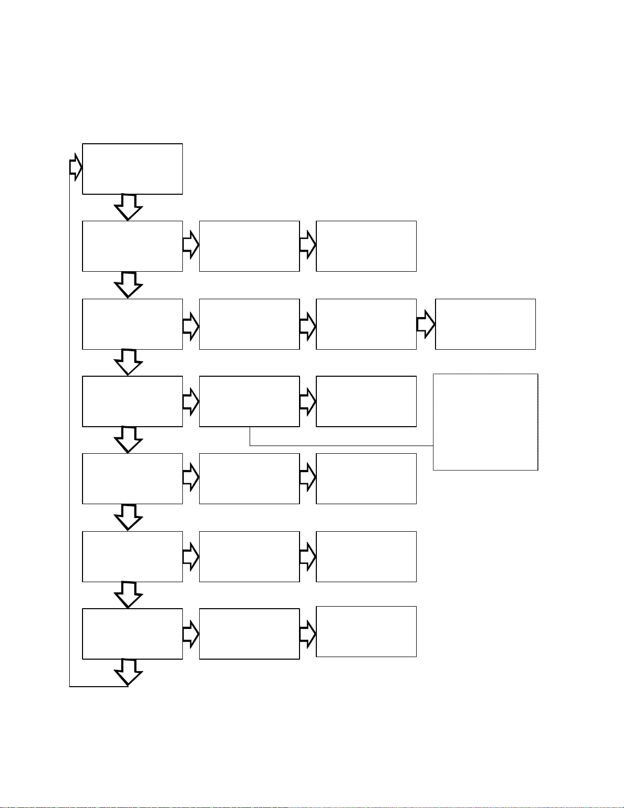
MODE COMMANDS
PRESS
MODE
TEMPORARY MODE COMMANDS WILL
RETURN TO NORMAL OPERATION UPON
EACH ARM OR DISARM SIGNAL.
PRESS MODE
1 TIME
2 TIMES
3 TIMES
4 TIMES
3RD
CHANNEL
TEMPORARY
CHIRP OFF
TEMPORARY
PREWARN OFF
CAR 1
PRESS
TRUNK
PRESS
TRUNK
PRESS
TRUNK
PRESS
TRUNK
ARM
DISARM
NOTE: TEMPORARY
PREWARN OFF CAN
ONLY BE MADE WITH
THE RF-700 DISARMED.
WHEN DELETED, THE
SIREN OR HORN WILL
CHIRP 3 TIMES.
5 TIMES
CAR 2
6 TIMES CAR 3
4
PRESS
TRUNK
PRESS
TRUNK
Page 5
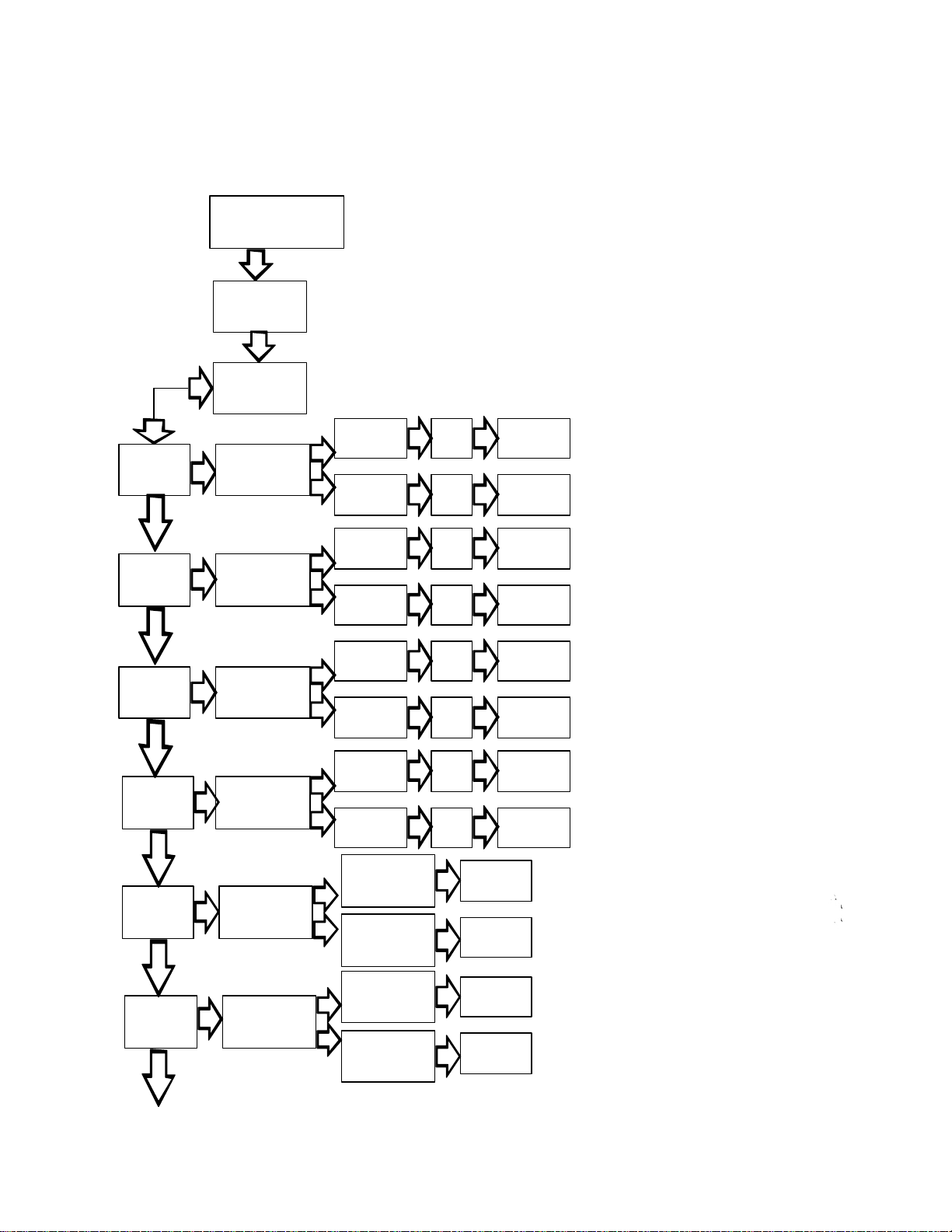
Many features of the RF-700 such as shock sensor adjustment, manual or passive arming, etc. are
programmed through the PROGRAM COMMANDS mode of the transmitter.
1
TIME
2
TIMES
3
TIMES
PRESS MODE
FOR 3 SECONDS
PROGRAM
PRESS
MODE
SENSOR
BYPASS
PASSIVE
ARMING
AUTOMATIC
REARM
PRESS
ARM
PRESS
DISARM
PRESS
ARM
PRESS
DISARM
PRESS
ARM
PRESS
DISARM
PROGRAM COMMANDS
THE RF-700 MUST BE DISARMED TO
ENTER ANY PROGRAM COMMANDS.
NOTE: IF A SINGLE RF-700
TRANSMITTER IS USED TO CONTROL
SECOND OR THIRD VEHICLES, THESE
PROGRAM COMMANDS ARE ONLY
AVAILABLE TO THE PRIMARY VEHICLE.
ON
OFF
ON
OFF
ON
OFF
PRESS
TRUNK
PRESS
TRUNK
PRESS
TRUNK
PRESS
TRUNK
PRESS
TRUNK
PRESS
TRUNK
CONFIRMED WITH 3 CHIRPS
CONFIRMED WITH 3 CHIRPS
CONFIRMED WITH 3 CHIRPS
CONFIRMED WITH 3 CHIRPS
CONFIRMED WITH 3 CHIRPS
CONFIRMED WITH 3 CHIRPS
PRESS
ARM
ON
4
TIMES
5
TIMES
6
TIMES
CONTINUED ON FOLLOWING PAGE
PREWARN
PREWARN
ADJUST (*)
SENSOR
ADJUST
PRESS
DISARM
SENSITIVITY
INCREASE
PRESS ARM
SENSITIVITY
DECREASE
PRESS DISARM
SENSITIVITY
INCREASE
PRESS ARM
SENSITIVITY
DECREASE
PRESS DISARM
OFF
PRESS
TRUNK
PRESS
TRUNK
PRESS
TRUNK
PRESS
TRUNK
NOTE: FACTORY SENSOR SETTINGS ARE SET
AT 8. RESETTING THE TRANSMITTER RETURNS
THE SENSOR SETTINGS TO 8.
5
PRESS
TRUNK
PRESS
TRUNK
CONFIRMED WITH 3 CHIRPS
CONFIRMED WITH 3 CHIRPS
CONFIRMED WITH 4 CHIRPS
(*) IMPORTANT: After prewarn adjustment is made
press TRUNK, siren will chirp, then press MODE,
then press TRUNK one more time. Siren will chirp.
CONFIRMED WITH 4 CHIRPS
CONFIRMED WITH 4 CHIRPS
CONFIRMED WITH 4 CHIRPS
Page 6
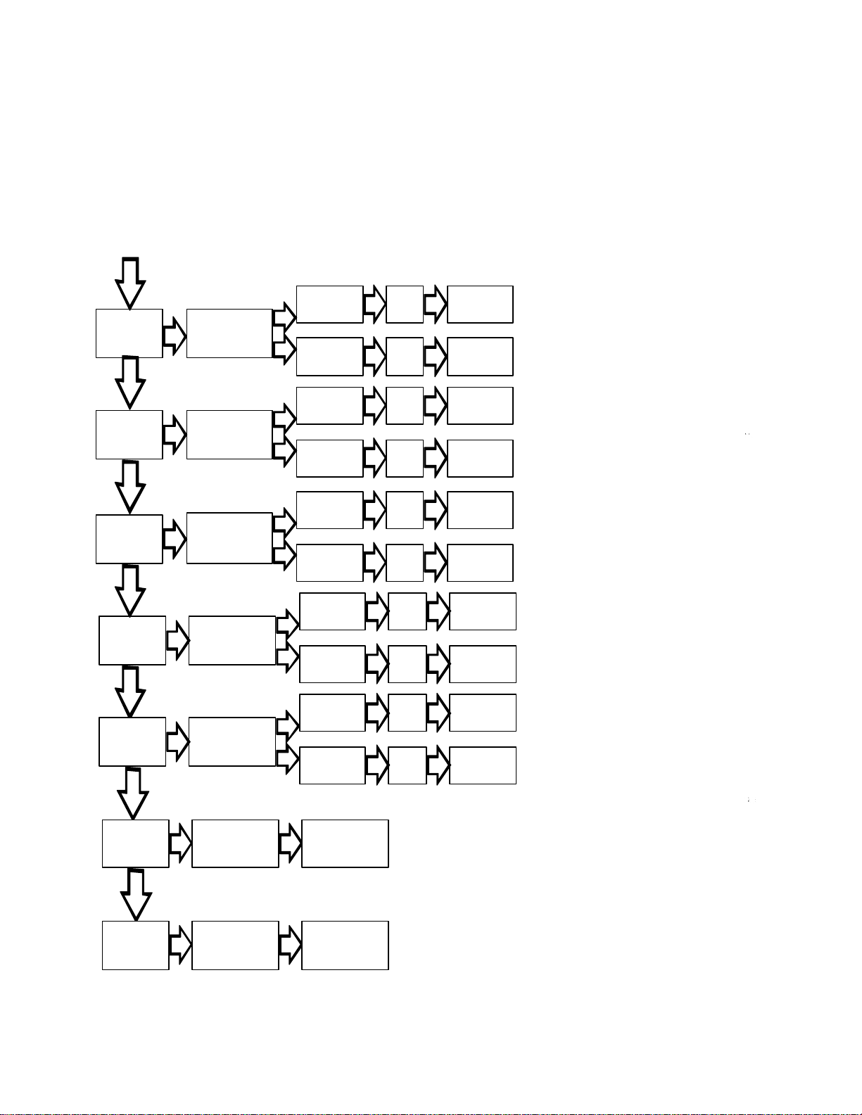
PROGRAM COMMANDS (CONTINUED)
THE RF-700 MUST BE DISARMED TO
ENTER ANY PROGRAM COMMANDS.
7
TIMES
8
TIMES
9
TIMES
10
TIMES
PASSIVE
LOCK
IGNITION
CONTROL
LOCK/UNLOCK
CHIRP
(SIREN ONLY)*
* REFER TO
INSTALL MANUAL
FOR HORN CHIRP
BACK
LIGHT
PRESS
ARM
PRESS
DISARM
PRESS
ARM
PRESS
DISARM
PRESS
ARM
PRESS
DISARM
PRESS
ARM
PRESS
DISARM
ON
OFF
ON
OFF
ON
OFF
ON
OFF
PRESS
TRUNK
PRESS
TRUNK
PRESS
TRUNK
PRESS
TRUNK
PRESS
TRUNK
PRESS
TRUNK
PRESS
TRUNK
PRESS
TRUNK
CONFIRMED WITH 3 CHIRPS
CONFIRMED WITH 3 CHIRPS
CONFIRMED WITH 3 CHIRPS
CONFIRMED WITH 3 CHIRPS
CONFIRMED WITH 3 CHIRPS
CONFIRMED WITH 3 CHIRPS
NO CHIRP SIGNAL
NO CHIRP SIGNAL
11
TIMES
12
TIMES
13
TIMES
TEST
RESET TO
FACTORY
DEFAULTS
EXIT
PRESS
ARM
PRESS
DISARM
PRESS
TRUNK
PRESS
TRUNK
ON
OFF
CONFIRMED WITH 3 CHIRPS
NO CHIRP CONFIRMATION UNLESS
A SENSOR ADJUSTMENT HAS BEEN MADE
6
PRESS
TRUNK
PRESS
TRUNK
CONFIRMED WITH 4 CHIRPS
CONFIRMED WITH 3 CHIRPS
Page 7

DISARM - ALARM MODE
The default (factory) settings for the program commands are as follows.
Sensor Bypass OFF
Passive Arming OFF
Automatic Rearm OFF
Prewarn Circuit OFF
Prewarn Sensor Adjustment 8
Main Shock Sensor Adjustment 8
Passive Door Lock OFF
Ignition Control Lock/Unlock OFF
Siren Chirp ON
Transmitter Backlight OFF
Reset (Return to Defaults) N/A
Exit (Exit Program Mode) N/A
A bracketed (M) or (P) will appear throughout this manual after any feature, function, or option heading
indicating settings or adjustments are made through the RF-700 transmitter. Consult the flow chart for
instructions.
ICONS APPEAR HERE
LCD READOUTS
APPEAR HERE
ARM - ALARM MODE
ON - PROGRAM MODE
SENSOR ADJUST - UP
TRUNK RELEASE
ENTER - COMMAND MODE
ENTER - PROGRAM MODE
TEMPORARY VALET
PUSH BOTH ARM & DISARM BUTTONS
AT THE SAME TIME. SIREN OR HORN
WILL CHIRP 3 TIMES TO CONFIRM.
7
OFF - PROGRAM MODE
SENSOR ADJUST - DOWN
MODE SELECT
Page 8

1. ARM
Press the ARM button once to arm. The vehicle horn, or siren (*) will chirp one (1) time, the parking
lights will flash one (1) time, and all doors will lock (**).
NOTE: To accommodate vehicles with slow-dim, or delayed interior lighting, the pin switch trigger circuit
of the RF-700 will wait 45 seconds after arming before becoming active. The trunk trigger circuit, and
shock sensor circuit will be immediately active upon arming. The starter interrupt circuit becomes active
on alarm trigger. Additionally, the RF-700 will trigger if any attempt is made to turn on the ignition when
armed.
2. LED STATUS INDICATOR OPERATION
1. LED OFF = DISARMED OR IN VALET MODE
2. LED FAST FLASHING = PASSIVE ARMING OR AUTOMATIC REARMING
3. LED FLASHING = ARMED
4. LED FLASHING 1 TIME QUICKLY = DOOR BREACH (DISARM)
5. LED FLASHING 2 TIMES QUICKLY = TRUNK BREACH (DISARM)
6. LED FLASHING 3 TIMES QUICKLY = SENSOR BREACH (DISARM)
NOTE: If the automatic rearm feature has been chosen through the transmitter, a door must be opened
after disarming. If a door is not opened, the RF-700 will automatically rearm in 60 seconds, and the LED
will continue to flash. See section (D) AUTOMATIC REARM for details.
3. TO DISARM THE RF-700
Press the DISARM button once to disarm. The vehicle horn, or siren (*) will chirp two (2) times, the
parking lights will flash two (2) times, and the doors will unlock (**).
NOTE: If optional PRIORITY DOOR UNLOCK was installed, only the driver’s door will unlock upon
disarm. To unlock all remaining doors, push the disarm button one more time within five (5) seconds.
NOTE (*): The RF-700 is capable of three methods for audible alarm trigger. You may choose at the
time of installation to honk the vehicle’s horn, you may choose the standard electronic siren, or both.
NOTE (**): Your vehicle must be equipped with power door locks. Optional relays may be required.
Please read the manual for other door lock functions and/or options that may be controlled by the RF-
700.
NOTE: If domelight supervision has been installed, the vehicle’s dome light(s) will illuminate with the
disarm signal. The domelight will remain on for 60 seconds, or turn off immediately after switching on the
ignition.
8
Page 9

4. AUDIBLE BREACH WARNING
In addition to the LED status indicator, the RF-700 is equipped with an audible breach warning to inform
you that the alarm has been triggered in your absence. Upon disarming, the siren or horn will chirp four
times, and the parking lights will flash four times.
5. ARM/DISARM CHIRP DELETE FROM REMOTE (M) or (P)
(Vehicle horn or siren)
The arm/disarm chirp sound may be deleted temporarily or permanently if desired. If deleted temporarily,
the chirp sound will return upon the next arm or disarm signal. If deleted permanently, arm/disarm
confirmation may be made via the flashing parking lights.
6. PANIC FUNCTION
The RF-700 remote control may be used as a remote control panic switch to trigger the horn or siren in
cases of emergency. To activate the PANIC FUNCTION press and hold the ARM or DISARM button
on the remote transmitter for a minimum of three (3) seconds. The vehicle horn or siren will sound. To
stop the PANIC FUNCTION press the DISARM button on the transmitter one more time.
NOTE: If the DISARM button is used to start the panic function be sure the alarm is rearmed before
leaving the vehicle.
7. TRANSMITTER BACKLIGHT (P)
The XT-64 transmitter is equipped with an internal backlight to aid in its use at night, or in dark areas
such as parking structures.
The internal backlight will light each time a transmitter button is pushed. It will stay lit from two to five
seconds depending on the function chosen.
NOTE: Extended use of the transmitter backlight when not necessary will diminish battery life more
quickly.
8. EXIT TRANSMITTER SETTING MODE (P)
The PROGRAM COMMANDS setting mode must be closed before any alarm protection is possible.
9
Page 10

9. CHANGING THE REMOTE
TRANSMITTER BATTERY
The RF-700 remote transmitter uses one (1) 12
volt miniature battery, #EL12, #VR22, or
Radio Shack #23-144. It will provide
approximately six months of operation before
replacement is necessary.
To replace the battery, carefully remove the
case screw located at the end of the remote
transmitter where the key ring attaches to its
case. Use a small blade Phillips screwdriver.
Before removing the battery note the direction
of its terminals. Install the new battery exactly
the same, using caution so as not to bend, or
otherwise damage the battery contacts.
Replace the case cover and carefully tighten the
screw. Do not over-tighten the screw. Test the
transmitter to be sure it arms and disarms the
alarm.
NOTE: Should any
difficulity be experienced
after changing the battery.
reopen the transmitter
and push the reset switch
located above negative
battery terminal.
Reset switch
+
-
B. VALET/OVERRIDE SWITCH
NOTE: Both VALET and OVERRIDE functions are performed from the same switch.
1. OVERRIDE FUNCTION
The OVERRIDE FUNCTION may be used if the RF-700 remote is lost or inoperative. To operate
the OVERRIDE FUNCTION, enter the vehicle (alarm will sound). Switch the ignition to ON. Push
the momentary VALET/OVERRIDE switch. The alarm will stop. The RF-700 will be disarmed.
Quickly replace or service the remote transmitter to insure continued vehicle protection.
2. VALET FUNCTION (TEMPORARY)
To engage temporary valet alarm must be disarmed and the ignition off. Press both arm and disarm
buttons on the transmitter at the same time. The RF-700 will respond with three confirming chirps.
The RF-700 may be placed into temporary valet mode when valet parking the vehicle. Temporary
valet mode will allow the vehicle to be driven without giving the valet operator the RF-700 transmitter.
10
Page 11

In addition, the temporary valet mode will protect the trunk or hatch and trigger the RF-700 either is
opened, without the remote control, while in the care of the valet.
NOTE: The dedicated trunk trigger wire must be utilized for this function.
3. VALET FUNCTION WITH PASSIVE ARMING
If PASSIVE (Automatic) arming is selected, the RF-700 may be placed into the VALET (stand-by)
mode to allow for vehicle service, washing, or attendant parking without self-arming after the ignition has
been switch off, and without leaving the RF-700 remote control with unauthorized individuals.
To operate the VALET FUNCTION, push the momentary VALET/OVERRIDE switch to ON for 3
seconds. The siren or horn will chirp 3 times.
To return to normal operation, push the momentary VALET/OVERRIDE switch to ON for 3 seconds.
The siren or horn will chirp 2 times.
4. KEYLESS ENTRY MODE
In the valet mode, the vehicle doors can be locked and unlocked, and the trunk or hatch can be
released using the remote, if remote door lock/unlock and trunk/hatch release (*) has been installed.
However, there will be no chirp or LED confirmation. It is strongly recommended that the driver
visually confirm that the doors are locked or unlocked.
NOTE (*): Your vehicle must be equipped with power door locks, and electronic trunk/hatch release.
Optional relays may be required.
C. PASSIVE OPERATION (P)
The RF-700 provides a choice of arming capabilities. The alarm can be set to automatically arm each
time the vehicle is parked, or it may be armed manually. Refer to manual arming at the beginning of this
manual. The selection for PASSIVE (Automatic) or MANUAL (Active) arming is done with the
remote transmitter.
NOTE: The factory default setting is MANUAL arming.
1. PASSIVE ARMING
Switch off the vehicle ignition and exit the vehicle. Insure all protected openings are closed. The RF700 will count down for 30 seconds. After 30 seconds, the vehicle horn or siren will chirp one time,
and the parking lights will flash one time indicating the RF-700 has armed.
NOTE: If the optional power door lock feature is installed, and the PASSIVE (Automatic) door lock
feature has been selected during installation, the doors will automatically lock 15 seconds after the
PASSIVE arming cycle is completed.
11
Page 12

2. DISARMING WITH PASSIVE (AUTOMATIC) ARMING
Disarming is accomplished in the same manner as with MANUAL arming. Refer to Section A of this
manual.
NOTE: If domelight supervision has been installed, the vehicle’s domelight(s) will illuminate with the
disarm signal. The domelight will remain on for 60 seconds, or immediately turn off when the ignition is
switched on.
D. AUTOMATIC REARMING (P)
The RF-700 is equipped with an automatic rearming circuit that will return the alarm to a fully armed
state if a door is not opened within 60 seconds after disarming, regardless of which method was used to
arm. The automatic rearm circuit can be eliminated at the time of installation.
E. IGNITION CONTROL POWER DOOR LOCK SYSTEM (P)
When installed with remote power door lock/unlock, the vehicle’s doors will automatically lock 15
seconds after the engine has been started. (*) The doors will automatically unlock when the ignition is
switched off. To avoid any undesirable lockout, the doors will not lock if any door is left open.
This feature is selectable at the time of installation. If the ignition control door lock system is not chosen,
the doors will not lock automatically in the passive arming mode. However, the doors will lock in the
manual arming mode, and with the automatic rearming mode.
(*) The ignition control door lock system will be cancelled if a door is opened before the 15-second
time limit has lapsed. To relock the doors, push the vehicle’s power door lock button.
NOTE: Use of the ignition control door lock system will not interfere with any factory installed child
door lock safety system.
F. TRIGGER TEST AND TRIGGER CONNECTION TEST (P)
The RF-700 is equipped with a trigger connection test mode that will allow you to check each
protected opening, as well as the shock sensor to insure that they have been connected to the RF-700.
In this mode, opening each door, the trunk or hood (if connected to the alarm), or sharply kicking one
of the vehicles tires will chirp the siren or horn one time indicating the connection. The RF-700 must be
disarmed for this test.
12
Page 13

IMPORTANT NOTE: PROGRAM COMMANDS must be reentered and TEST MODE turned off
before any alarm function is possible.
You may also test the RF-700 actively (when armed) by opening any protected opening, or sharply
kicking one of the vehicle’s tires.
If triggered in the armed condition, the RF-700 will sound the vehicle horn or siren, and flash the
parking lights for 30 or 60 seconds depending upon which alarm run time was chosen at the time of
installation. It will then stop and automatically reset and rearm. If the violation continues, the alarm will
sound and the lights will flash for two (2) 30 or 60 seconds cycles.
G. REMOTE CONTROL TRUNK/HATCH RELEASE FEATURE (Optional)
The RF-700 remote transmitter may be used to release your vehicle’s trunk or hatch release. (*)
To remotely release the vehicle trunk or hatch, if the alarm is armed, press the DISARM button on the
remote transmitter, then press the TRUNK button for one second. The trunk or hatch will automatically
release. If the alarm is disarmed, press only the TRUNK button for one second. (**)
(*) Your vehicle must be equipped with an electronic trunk or hatch release.
(**) If the alarm was armed and you do not intend to drive the vehicle, you must rearm the RF-700.
H. SHOCK SENSOR (P)
The standard SIS-5 shock sensor will trigger the RF-700 when, for example, a window is broken, or
when the body of the vehicle is subjected to a shock, such as being struck by another vehicle when
parked.
Because vehicles vary greatly, the amount of sensitivity needed to trigger the SIS-5 will also vary. The
SIS-5 is adjustable through the remote transmitter to allow precise adjustment to accommodate the
needs of your vehicle. Consult the program commands flow chart for shock sensor adjustment.
NOTE: As a rule of thumb, over-adjustment will result in frequent false triggers, under-adjustment will
result in poor response should a violation occur.
NOTE: Adjusting the SIS-5 will also affect adjustment of its own prewarning circuit. However, any
other added sensors, either trigger or prewarning, will not be affected. Those sensors must be adjusted
separately.
13
Page 14

I. SHOCK SENSOR BYPASS FEATURE (P)
Under certain conditions where the vehicle will be subject to heavy traffic, or environmental effects, you
may wish to bypass the SIS-5 shock sensor ,optional sensor for that particular arming cycle.
J. PREWARNING SENSOR CIRCUIT (Standard & Optional) (M) or (P)
The RF-700 offers the dual stage SIS-5 impact sensor to prewarn a light impact on the vehicle with two
siren or horn chirps, and two light flashes each time the prewarn detects the light impact. The prewarn
portion of the SIS-5 sensor will not trigger the alarm. Additionally, a separate prewarn input is
provided to connect other sensors to further enhance the prewarn feature.
NOTE: Utilizing the prewarn delete feature from PROGRAM COMMANDS will delete both the
standard shock sensor prewarn circuit, as well as any optional sensors connected to the separate
prewarn input.
NOTE: Temporarily deleted sensor(s) from MODE COMMANDS will return to normal operation
upon disarming the RF-700. The temporary prewarn delete procedure must be followed each time the
RF-700 is armed.
NOTE: The prewarn feature is set inactive by the factory, and must be activated through the transmitter
if this feature is desired.
K. THIRD CHANNEL OUTPUT FEATURE (M)
AutoPage provides a third output channel accessed from the remote transmitter to allow control over
optional features such as, power window roll-up modules, remote engine starters, etc. Consult with
your AutoPage dealer for specifics on which optional equipment may be connected to this output.
NOTE: Due to the wide range of modules and accessories available, AutoPage cannot guarantee that
the third channel output feature will function with all types of optional modules and accessories.
L. PROGRAMMING THE REMOTE TRANSMITTERS (PRIMARY VEHICLE)
NOTE: The factory default setting of the transmitters is CAR #1. It is not necessary to enter a mode
command to program the transmitters to the primary vehicle.
14
Page 15

The RF-700 includes two, 4 button mini remote control transmitters with LCD (Liquid Crystal Display)
readouts which must be programmed to the alarm before any alarm function is possible. This action is
normally done at the time of installation, however there may be occurrences when you wish to enter the
programming mode.
NOTE: Each time the programming mode is entered, all previously programmed transmitter codes will
be automatically deleted and must be reprogrammed. This is an important security feature. If any
transmitter is lost or stolen, enter the programming mode and reprogram existing transmitters.
Transmitters can only be programmed by entering the programming mode.
NOTE: Any transmitters programmed to the RF-700 will remain in memory during times when certain
vehicle service procedures make it necessary to disconnect the battery.
To program the RF-700 transmitters, follow the directions as written below, in their exact order!
To enter the programming mode switch the ignition ON, then push the momentary valet/override switch
five times. The siren or horn will chirp three times. Push the ARM button on one of the transmitters.
The siren or horn will chirp one time to confirm the RF-700 has accepted the code. Push the ARM
button on the remaining transmitter. The siren or horn will chirp one time to confirm the RF-700 has
accepted the code. To close the programming mode, switch off the ignition.
NOTE: The RF-700 will accept up to four transmitters. Consult your AutoPage dealer for the
purchase of additional transmitters.
1. TWO AND THREE VEHICLE OPERATION (M)
Press the MODE button on the transmitter to select CAR #2 or CAR #3. Consult the MODE
COMMANDS flow chart for details.
VEHICLE #2 (*)
Enter the programming mode on vehicle #2 and push the ARM button on the transmitter. The vehicle
horn or siren will respond with a confirming chirp.
VEHICLE #3 (*)
Enter the programming mode on vehicle #3 and push the ARM button on the transmitter.
The vehicle horn or siren will respond with a confirming chirp.
(*) All vehicles must be equipped with RF-700 alarm systems.
NOTE: If the transmitter for the primary vehicle has been programmed to operate one or two other
vehicles, it will not be possible to set PROGRAM COMMANDS on CAR #2 or CAR #3 with the
15
Page 16

primary transmitter from CAR #1. You must program CAR #2 and CAR #3 with their respective
primary transmitters.
NOTE: Program each vehicle separately.
AUTOPAGE ALARM ACCESSORIES
AP4000EX
AutoPage originated vehicle security paging over 18 years ago. The AP4000EX is our latest version
providing a full four watts of output, and a unique digital format. One AP4000EX pager is capable of
monitoring up to three vehicles. (*) The pager will notify you with a choice of audible, visual, or
vibration alerts. Its memory will also store the last trigger.
(*) Second and third vehicles must be equipped with an optional AP4000EX transmitter.
AP4000DX
The AP4000DX is a full four-watt paging system. The signal is received by a handsome belt-clippaging receiver indicating your RF-700 has been triggered, even if you cannot hear the siren.
RS-32 Dual Stage Perimeter Protection Sensor.
The RS-32 utilizes microwave technology that emits dual protective fields. The easy and separate
adjustment of the exterior and interior fields allows the RF-700 to be armed and provide maximum
protection in convertible vehicles parked with the top down, and equally good protection in enclosed
vehicles.
SIS-10 Air Movement Sensor
The SIS-10 super low frequency vibration sensor has successfully integrated an electret electrostatic
transducer and a low pass filter, creating a new and cost effective air movement sensor. If installed in a
closed vehicle, any movement of air inside the vehicle, for example, opening a door will trigger the
sensor. Applications of the SIS-10 are limitless. It will be ideal to monitor a vehicle’s doors, trunk or
hatch, an RV, a closed cabin on a vessel, and so on. The SIS-10 can also replace glass breakage
sensors. The advantage is that a single SIS-10 can cover all doors, rear hatch, windows, and sunroof,
even if there is no pin switch.
AC-68 Power Window Module
The AC-68 power window control module can control the up or down motion of two windows, or one
window and a sunroof. (*)
16
Page 17

(*) Vehicle must be equipped with power windows, and/or power operated sunroof.
RK-1 Relay Kit
A pre-wired relay and socket for starter interrupt, and other optional functions of the RF-700 requiring
a relay for operation.
XT-64
Additional/Replacement remote control transmitter.
LIMITITED LIFETIME WARRANTY PROVISIONS
(U.S. and Continental U.S. Only)
1.AutoPage, Inc. WARRANTS that this new unit has been thoroughly inspected and
tested at the factory prior to delivery. Your AutoPage equipment is guaranteed for
"life" to the original purchaser/user of the equipment under the following conditions: If
the product proves defective (according to AutoPage's testing) within the first year,
the defective unit may be exchanged or repaired free of charge. "Proof of Purchase"
(dated sales receipt) must accompany all warranty returns; otherwise, your returns
will be rejected and sent back. After one (1) year, the purchaser should ship the
unit pre-paid to AutoPage with a money order in the amount of $20.00 to cover
handling and shipping charges. Note: The WARRANTY CARD on the back of this
page may be required to receive warranty services.
2. This WARRANTY will be considered VOID if the equipment has been misused,
neglected, improperly serviced, altered, dropped or damaged by water, contrary to
the AutoPage INSTRUCTION MANUAL. Or, if used with accessories not
approved by AutoPage, which may have contributed to the defect.
3. The purchaser's remedies under this WARRANTY shall be limited to the repair or replacement
of electronic components only. THE FOLLOWING IS NOT COVERED: Damages or
deterioration to cases, batteries, covers and cabinets; the cost of repairs, replacement and labor of
which shall be borne by the purchaser even if occurring during the WARRANTY period.
4. Any equipment or parts which are claimed to be defective under this WARRANTY must be sent
to the AutoPage Service center with "proof of purchase" at purchaser's expense prior to such return,
a Return Authorization Number should be obtained. AutoPage will return the equipment, charges
prepaid. Warranty Service can be provided through the dealer where the equipment is originally
purchased.
5. Any unexpired WARRANTY shall be applicable to equipment and parts in the
possession of the original purchaser only.
17
Page 18

6. THIS WARRANTY IS IN LIEU OF ANY AND ALL OTHER WARRANTIES,
EXPRESSED OR IMPLIED, INCLUDING BUT NOT LIMITED TO ANY WARRANTY OF
MERCHANTABILITY OR FITNESS FOR A PARTICULAR PURPOSE.
7 AutoPage shall not be liable, under the foregoing WARRANTIES or otherwise, for: Any personal
injury of any kind to the purchaser, its employees or agents or anyone else whomsoever resulting
directly or indirectly from the use or presence of the equipment or parts; Consequential damages of
any kind; Any inability of the purchaser to use the equipment.
This WARRANTY CARD is for your record. However, AutoPage reserves the right to request you to
submit this WARRANTY CARD which must have complete information to receive warranty service.
Please keep this card in a secured place.
AUTOPAGE WARRANTY SERVICE CARD
Model RF-700
Serial #
CUSTOMER TO COMPLETE DEALER TO COMPLETE
Mr/Mrs/Ms
Your Name (Piease print)
Address
City , State , Zip
Telephon Number
Year / Make / Model of Vehicle
Company Name
Dealer’s Address
City , State , Zip
Dealer’s Telephon Number
Date of Installation / Purches
Dealer Signature
18
Page 19

“Proof of purchase" which includes the store name and date of purchase must
accompany all warrantyd returns.
It is your responsibility to keep this card for any future warranty service.
-------------------------------- For You Records --------------------------------
DATE SERVICE COMPLETED
19
Page 20

20
 Loading...