

DRW160535AE
Autonics
WiFi to RS485.USB
Communication Converter
SCM-WF48
I N S T R U C T I O N M A U A L
Please read the following safety considerations before use.
I!.]
Safety Considerations
Please observe all safety considerations for safe and proper product operation to avoid hazards.
※
※
symbol represents caution due to special circumstances in which hazards may occur.
Warning Failure to follow these instructions may result in serious injury or death.
Caution
Warning
1. Fail-safe device must be installed when using the unit with machinery that may
cause serious injury or substantial economic loss. (e.g. nuclear power control,
medical equipment, ships, vehicles, railways, aircraft, combustion apparatus, safety
equipment, crime/disaster prevention devices, etc.)
Failure to follow this instruction may result in re, personal injury, or economic loss.
2. Do not disassemble or modify the unit.
Failure to follow this instruction may result in re.
3. Do not connect, repair
Failure to follow this instruction may result in re.
4. Check 'Connections' before wiring.
Failure to follow this instruction may result in malfunction and damage on the product or PC.
Caution
1. Use the unit within the rated specications.
Failure to follow this instruction may result in re or product damage.
2. Use dry cloth to clean the unit, and do not use water or organic solvent.
Failure to follow this instruction may result in re.
3. Do not use the unit in the place where ammable/explosive/corrosive gas, humidity,
direct sunlight, radiant heat, vibration, impact, or salinity may be present.
Failure to follow this instruction may result in re or explosion.
4. Keep metal chip, dust, and wire residue from owing into the unit.
Failure to follow this instruction may result in re or product damage.
5. Do not disconnect connector or power, when the product is operating.
Failure to follow this instruction may result in re or malfunction.
I!.]
Unit Description
Thank you for choosing our Autonics product.
Failure to follow these instructions may result in personal injury or product damage.
, or inspect the unit while connected to a power source.
1
2
I!.]
Specications
●Standard specifications
Power supply 24VDC
Allowable voltage range 12-28VDC
Power consumption Approx. 3W
Communication type RS485, USB, WiFi
Isolation resistance
Protection circuit Reverse polarity protection circuit, surge protection circuit
Dielectric strength 1,000VAC 50/60Hz for 1 min (between external terminal and case)
Noise immunity
Vibration
Shock 500m/s
Ambient temp. -10 to 55℃, storage: -20 to 60
Environ
I
-ment
Ambient humi. 35 to 80%RH, storage: 35 to 80%RH
I
Protection P20 ( EC standards)
Mounting DIN rail or panel mounting
Accessories
Approval
※
1
Weight
※1: The weight includes packaging. The weight in parenthesis is for unit only.
※
Environment resistance is rated at no freezing or condensation.
●RS-485 communication specifications
Connection RS-485
Standard EIA RS-485
Communication method 2-wire half duplex
Synchronous method Asynchronous
Effective com. distance Max. 800m
Communication speed
※
1
Data bit
※
1
Stop bit
※
1
Parity bit
Multi-drop Max. 31 multi-drop
Connection type 4-wire screw terminal (2-wire communication method)
1: You can set communication speed and stop bit, parity bit by DAQMaster.
※
●WiFi communication specifications
Protocol TCP/ P ( Pv4)
Standard 802.11b/g/n ( EEE 802.11b) compatible
Communication speed Max. 11Mbps
Frequency range 2.4 to 2.497GHz
Security WEP, WPA, WPA2-PSK, Enterprise
Antenna 2dBi external antenna
Communication distance Max. 100m
●USB communication specifications
Power 5V, 500mA
Standard USB 2.0 (compatible sub-transmission)
Communication method 2-wire half duplex
Connections USB 2.0 Mini B type (male)
Communication distance Max. 1m ± 30%
I!.]
Dimensions
Over 200MΩ (at 500VDC megger between external terminal and case)
±500V the square wave noise (pulse width: 1㎲) by the noise simulator
1 5mm amplitude at frequency of 10 to 55Hz (for 1 min) in each X, Y,
Z direction for 2 hours
2
(approx. 50G) in each X, Y, Z direction for 3 times
USB 2.0 Mini B type cable (length: 1m): 1
Connector for RS-485 (4-pin, male type): 1
Approx. 160g (Approx. 57g)
※
1
4800, 9600 (default), 19200, 38400, 57600, 115200bps
5-bit, 6-bit, 7-bit, 8-bit(default)
1-bit (default), 2-bit
None (default), Even, Odd
108.5
76 3
41.52-Ø3.5
℃
(unit: mm)
● Panel cut-out
2-M3 TAP
39
45
39
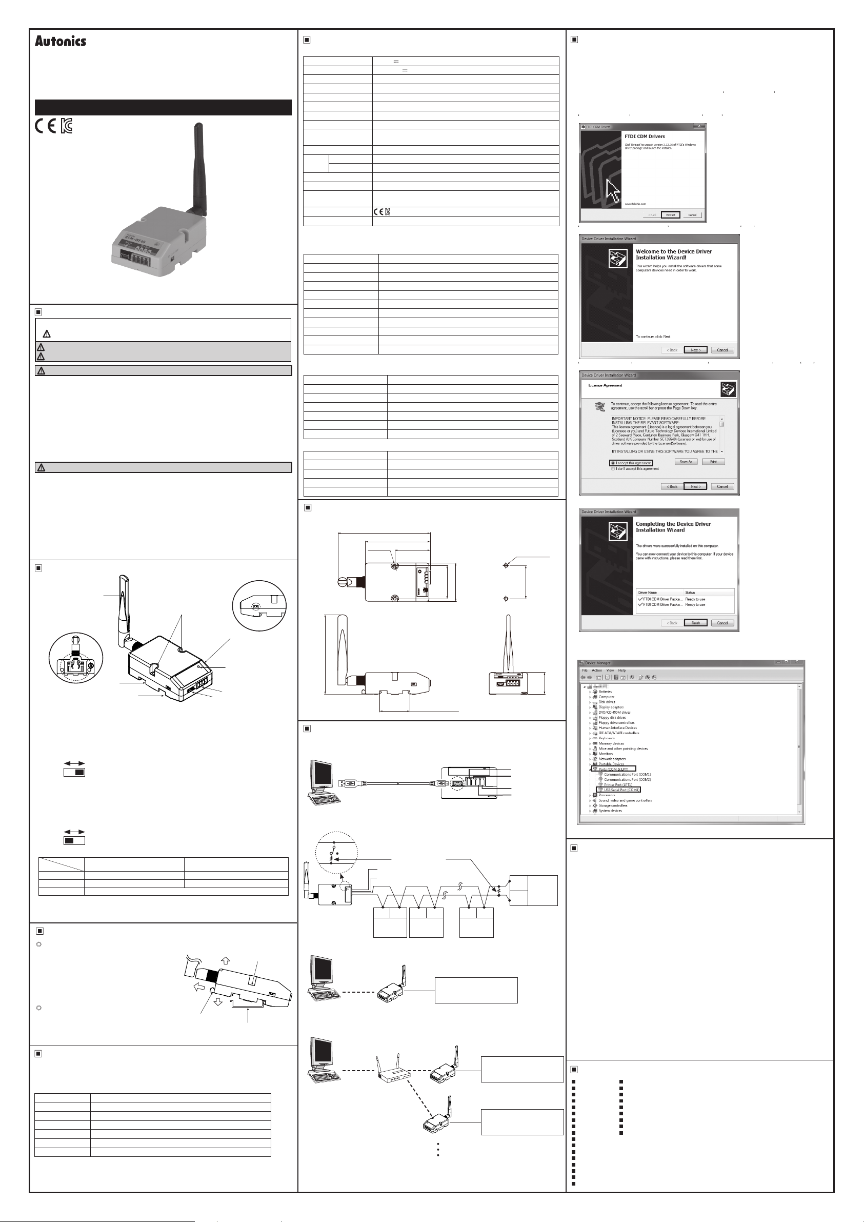
USB Driver Installation
It describes based on Windows 7 operating system.
※
Installation method may be different by operating system of PC.
When PC is connected NTERNET and the unit is connected with PC via USB port, PC
searches and installs the driver automatically.
If auto driver installation is fail, follow the below order to install the driver.
1) Visit our web site and download SCM-WF48 Driver .
2) Unzip the downloaded file at the desired directory.
3) Connect the unit at USB port of the PC and run CDM21216_Setup exe at the directory.
4) FTDI CDM Drivers dialog box appears. Click Extract . Files are extracted.
FTDI
COM
Drivers
Od.blradto~==2.12.!6off1Df,
oifflrpod<agearidlu'dllhe
< B
5) Device Driver Installation Wizard dialog box appears. Click Next.
Welcome
I
nst
allation
lh1wizardheip1youils.althesdtwan,
CDTµJersdevk:esneedinorda" loffllril
Tocortrue,clid<Neld
6) License Agreement dialog box appears. Select I accept this agreement and click Next.
D~c"'
Dri=
r l
mlallation Wizard
"""""'-
Tococtrue.lKX:eptthefolmwlgkense~.To~;,dtheertre
~ .usethescrolbarorpteS$the P
l~PORTANT
NOTICE:
~T
(\..ic
d2Seaward Place.Certooon
Scotland
ciiv«sdlw.,reprovidedbythel..icenSOl(Soflw.n)
BY l~STALUNG
jce) I
0
1don1acce,;,tlhis~
7) Driver installation is completed.
PLEASE
~=-~t!~R;~~w
M- oryru)
iVld
Fu:t.e
(UK~ti..-ber SC1JGG40){lhnsororwe)foruse d
OR USI
NG THIS
3e
cepttri
1
~
I
Completing
Installation Wizard
Thech.-MWffl!~~onNICXlftlll.ls
YouC¥1rwl#COl'W'l6dyo,sdeodoeto~ccwro.Aer.f'fOA.ldeYioe
csnewlhnllrudlonl.
--
v'
FTDI
COM
VFTDICOMDlttt.-Packb .. Reactftou,e
Wndo
t.ller
~
Wizard!
~Downkey
CAREFULLY BEFORE
Devices Hem
P
MK.GasgowG411HH
SOFTWARE
YOU
the
Device Driver
pisaerudthemfnt
....
Pacb
...
~10
•
PG
.-.
r:::;:r,
to the Device Driver
READ
Technology
~Sl!
ClnYer-
driver.sthat some
.
eoo
yru
atioM l.mted
REE
TO
THE
.
u,e
tE
•
[]
-
.
5
6
3
4
1. WiFi antenna
: Antenna for transmitting and receiving WiFi communication data.
t may be broken when excessive pressure is applied.
2. Fixing screw hole: Used for mounting the unit on a panel.
3. Rail Lock: Used for fixing this unit at DIN rail mounting.
4. Communication method switch
: Switch for select communication method.
USB RS485
For setting SCM-WF48 via DAQMaster, set USB.
※
5. Terminating resistance switch
: Switch for whether using terminating resistance (120 Ω, 1% (F) grade chip resistance,
1/4 W). (only when selecting RS485 communication method.)
RT: Uses terminating resistances.
OFF: Not use terminating resistance.
RT
6. Indicator: Indicator for statue of AP mode and Station mode.
Mode
State
Green ON Power ON Power ON
Red ON AP ready AP connection is complete
OFF No power
7. RS485 connector: Used for connecting RS485 communication cable.
8. USB connector: Used for connecting a PC, etc. with an USB cable.
I!.]
Installation
Mounting to and removing from DIN rail
(QJ
●
Mounting
1) Hang up the backside holder on a DIN rail.
2) Press the unit toward ① direction until it snaps.
●
Removing
1) Pull rail locks of the backside of this unit to
direction.
2) Pull the unit to ③ direction.
Mounting to panel
1) This unit is able to mount on a panel with two
fixing screws at center of both sides.
2) For mounting the unit, use M3 screws.
Tighten screws with 0.4 N m torque.
I!.]
Integrated Device Management Program [DAQMaster]
DAQMaster is the integrated device management program. Set the communication method
switch of SCM-WF48 as USB, and connect this unit and a PC with USB cable.
You can set the communication setting for SCM-WF48 by DAQMaster.
Visit our website and download DAQMaster.
Item Min. specications
System BM PC compatible computer with Intel Pentium Ⅲ or above
Operating system Microsoft Windows 98/NT/XP/Vista/Window 7/8/10
Memory 256MB +
Hard disk 1GB+ of available hard disk space
VGA Resolution: 1024×768 or higher
Others RS232 serial port (9-pin), USB port
※
The above specications are subject to change and some models may be discontinued
without notice.
※
Be sure to follow cautions written in the instruction manual and the technical
descriptions (catalog, homepage).
(default)
.......
OFF
(default)
~
AP mode Station mode
②
②
Rail Lock
7
8
Fixing
③
screw hole
①
DIN rail
93.4
35mm DIN rail
I!.]
Connections
When wiring the RS485 connector, use AWG 24 cable and tighten the connector screw with
※
a tightening torque of 0 22 to 0.4N.m with the screwdriver for M2 screw.
●
Cable connections
USB 2 0
A type (male)
Computer
●
Connection of SCM-WF48 and Multi-drop
B (-)
ON OFF
A (+)
SCM-WF48
●
AP mode
WiFi or
USB connection
l-------
Computer
●
Station mode
One wireless router can connect max. up to 254 units of SCM-WF48.
※
WiFi or
LAN connection
Computer
Before using this unit, set the communication method switch of SCM-WF48 as USB,
※
and connect this unit and a PC with USB cable. You can set the communication setting for
SCM-WF48 by DAQMaster.
USB 2.0 Mini
B type (male)
Terminating
resistance (120Ω)
GND
V (24VDC)
A (+) B (-) A (+) B (-) A (+) B (-)
RS485
DEVICE
J
SCM-WF48
Wireless
router
RS485
DEVICE
#1
#2
RS485
Autonics products which support
----c=J
WiFi
SCM-WF48
WiFi
SCM-WF48
A B V G
SCM-WF48
RS485
DEVICE
...
#30
Connectable max. 31 units of
communication
RS485
RS485
+RS485
-RS485
Ground
24VDC
B (-)
RS485
DEVICE
#31
A (+)
Connectable max. 31 units of
Autonics products which support
communication
Connectable max. 31 units of
Autonics products which support
communication
After installing the driver, you can check the driver installation at Device Manager.
※
Enter [Start]-[Control Panel]-[Device Manager] and extend Ports (COM & LPT) and USB
Serial Port (COM4) to check SCM-WF48 connection.
25.6
~
0 Di<~drivH
~
_,. Displaylldapt~n;
~
-,.0 DVD/CD-
ROM
~
~
~
~
~
~
~
~
~
~
~I§ Port~
If USB port is changed, reinstall the USB driver.
※
I!.]
Caution during Use
1. Follow instructions in 'Cautions during Use'. Otherwise, it may cause unexpected accidents.
2. 24VDC power supply should be insulated and limited voltage/current or Class 2, SELV power
supply device.
3. Use only designated connector and do not apply excessive power when connecting or
disconnecting the connectors.
4. Keep away from high voltage lines or power lines to prevent inductive noise.
In case installing power line and input signal line closely, use line filter or varistor at power
line and shielded wire at input signal line.
Do not use near the equipment which generates strong magnetic force or high frequency
noise.
5. Do not connect or disconnect the USB cable or RS485 cable quickly and repeatedly while
communicating.
It may cause damage or malfunction of the product and PC.
6. After supplying power, connect with the communication output product. When disconnect,
communication output product first and power last.
7. When connecting multiple SCM-WF48 units to a PC, number of COM port goes up in
sequential order and it takes some time to identify and assign number of COM port.
8. When connecting the RS485 communication output product, connect the terminating
resistance (120Ω) at each end of the communication cable.
9. Use twist pair wire for RS485 communication. If not, use A(+) and B(-) cables in the same
length.
10. Use USB cable of designated standard, and do not use extension cable.
11. This unit may be used in the following environments.
Indoors (in the environment condition rated in 'Specifications')
①
Altitude max. 2,000m
②
Pollution degree 2
③
Installation category I
④
I!.]
Major Products
Photoelectric Sensors Temperature Controllers
Fiber Optic Sensors Temperature/Humidity Transducers
Door Sensors SSRs/Power Contro lers
Door Side Sensors Counters
Area Sensors Timers
Proximity Sensors Panel Meters
Pressure Sensors Tachometers/Pulse (Rate)Meters
Rotary Encoders Display Units
Connector/Sockets Sensor Controllers
Switching Mode Power Supplies
Control Switches/Lamps/Buzzers
I/O Terminal Blocks & Cables
Stepper Motors/Drivers/Motion Controllers
Graphic/Logic Panels
Field Network Devices
Laser Marking System (Fiber, Co₂, Nd:YAG)
Laser Welding/Cutting System
dr~
,d
Floppy
dO<k
drivH
-1-i
Floppydrive<ontroll
.O;j;
Human lnt
..
hc"'
D~icH
IDEATA/ATAP!controll"'"
-=
Keyboar ds
.M.,mo,ydNKH
t!,
Mi{e llnd
olhff
pointing
Monitor<
-
N_,,rl<u!•pl~r<
-ii
Port~
bl~
Devic~
(COM & LP
]
~"'f°
Communication1 Port (COMl)
f-'J Communication, Port (
Print~, Port
LPTI
■
■
■
■
■
■
■
■
■
e~
devic~
COM.2}
DRW160535AE
 Loading...