

DRW160897AC
Autonics
Serial Converter Module
SCM SERIES
I N S T R U C T I O N M A N U A L
SCM-US
(USB/Serial Converter)
Thank you for choosing our Autonics product.
Please read the following safety considerations before use.
Safety Considerations
Please observe all safety considerations for safe and proper product operation to avoid hazards.
※
※
symbol represents caution due to special circumstances in which hazards may occur.
Warning Failure to follow these instructions may result in serious injury or death.
Caution
Failure to follow these instructions may result in personal injury or product damage.
Warning
1. Fail-safe device must be installed when using the unit with machinery that may cause
serious injury or substantial economic loss. (e.g. nuclear power control, medical equipment,
ships, vehicles, railways, aircraft, combustion apparatus, safety equipment, crime/disaster
prevention devices, etc.)
Failure to follow this instruction may result in re, personal injury, or economic loss.
2. Do not disassemble or modify the unit.
Failure to follow this instruction may result in re.
3. Do not connect, repair, or inspect the unit while connected to a power source.
Failure to follow this instruction may result in re.
4. Check 'Connections' before wiring.
Failure to follow this instruction may result in malfunction and damage on the product or PC.
Caution
1. Use the unit within the rated specications.
Failure to follow this instruction may result in re or product damage.
2. Use dry cloth to clean the unit, and do not use water or organic solvent.
Failure to follow this instruction may result in re.
3. Do not use the unit in the place where ammable/explosive/corrosive gas, humidity, direct
sunlight, radiant heat, vibration, impact, or salinity may be present.
Failure to follow this instruction may result in re or explosion.
4. Keep metal chip, dust, and wire residue from owing into the unit.
Failure to follow this instruction may result in re or product damage.
5. Do not disconnect connector or power, when the product is operating.
Failure to follow this instruction may result in re or malfunction.
Proper Usage
●TX Enable signal(RTS signal)
In case of SCM-38I and SCM-US48I, Tx_ Enable signal (RTS signal) is automatically generated
according to protocol (Do not need to generate signal on your own)
●Auto-loop Back
SCM-38I has Auto-look Back function. When using Auto-loop back function, please use as 'RS232C'
cable connections.
●Termination Resistor
RS485 Communication has many advantages such as fast transmission rate, long distance
communication and etc. But if the impedance of transmission line does not match to RS485 network
terminations, the reected wave will be generated.
In case of increasing the length of transmission line or using 1 N multi-drops, the reected wave may
cause transmission error.
Therefore in this case, please use termination resistor(100 to 120Ω) at both terminations.
Features
SCM-US SCM-38I SCM-US48I
●USB ↔ Serial
●Communication cable is
specifically designed to connect
to Autonics products.
●Non-isolation type
●Applicable OS: Windows
98/98SE/ME/2000/Server
2003/XP/Vista/7
●Built- in ferrite core cable for
noise reduction
●Both USB1.1, USB 2 0
compatible
●Data transmission/power supply
indicating LED
●Easy to connect with PC
●Built-in protection circuit
1: Some products requires the dedicated converter cable(EXT-US, sold separately).
※
1
※
Specications
Model SCM-US SCM-38I SCM-US48I
Power supply 5VDC USB bus power
Power consumption Approx. 1W Approx. 1.7W Approx. 1W
Max. com. speed
Communication type Half duplex type
Available com.
distance
Multi-drop
Protocol
Connection type
Isolation type Non-isolation Isolation
Dielectric strength
Isolation resistance
Noise immunity
Vibration
Shock
Environment
Approval
Accessory
Weight
1: USB bus Power is supplied from PC or USB host controller.
※
2: Protocol and Communication speed are set by Hyper terminal. DAQMaster, ParaSet, Modbus
※
Poll. When communicating with Autonics products, set communication speed to 9,600bps.
3: Some products requires the EXT-US(converter cable, sold separately).
※
4: The weight includes packaging. The weight in parenthesis is for unit only.
※
There might be some differences in the specication above depending on PC environment.
※
Environment resistance is rated at no freezing or condensation.
※
Installations
00
SCM-38I & SCM-US48I
Multi-layer
※
'B'(length of screw)
The above specifications are subject to change and some models may be discontinued
※
without notice.
Be sure to follow cautions written in the instruction manual and the technical descriptions
※
(catalog, homepage).
2
※
1,200 to 115,200bps (recommended: 9,600bps)
1.5m (not extension) Max. 1.2km
Data bit
Stop bit
Parity bit
-
-
-
USB: USB 2.0 A type (male)
Earphone jack
(4 pole stereo phone plug)
-
-
-
Mechanical
Malfunction
Mechanical 300m/s²(approx. 30G) in each X, Y, Z direction for 3 times
Malfunction 100m/s²(approx. 10G) in each X, Y, Z direction for 3 times
Ambient
temperature
Ambient
humidity
0.75mm amplitude at frequency of 10 to 55Hz (for 1 min) in each X, Y, Z direction
for 1 hour
0.5mm amplitude at frequency of 10 to 55Hz (for 1 min) in each X, Y, Z direction
for 10 min
-10 to 55℃, storage: -20 to 60
35 to 85%RH, storage: 35 to 85%RH
CE~
-
※
Approx. 80g
(approx. 41g)
There is no Serial Port in SCM-US48I.
SCM-38I
(RS232C/RS485 Converter)
●RS232C ↔ RS485
●Isolating RS485 Transceiver
(2500VRMS)
●Built-in protection circuit
●Tx-Enable signal (RTS signal)
is automatically generated
1
※
12-24VDCᜡ ±10% 5VDC USB bus power
Max. 31 multi-drop
5-bit, 6-bit, 7-bit, 8-bit
1-bit, 2-bit
None, Odd, Even
RS232C: D-sub 9-pin
3
※
RS485: 4-wire screw terminal
(2-wire communication type)
Between whole terminals
and case: 2000VAC
50/60Hz for 1 min
Between RS232C
and RS485: 2500VAC
50/60Hz for 1 min
100MΩ (at 500VDC megger)
±500V the squre wave noise(pulse width: 1㎲) by
the noise simulator
℃
Approx. 106g
(approx. 46g)
M3 screw bolt
Number of
layers (N)
1 23.5mm 20mm
'A'(height of layer)
2 46.5mm 43mm
Panel
3 69.5mm 66mm
4 92.5mm 89mm
SCM-US48I
(USB/RS485 Converter)
●USB ↔ RS485
●Isolating RS485
Transceiver(2500VRMS)
●Applicable OS: Windows
98/98SE/ME/2000/Server
2003/XP/Vista/7
●Built- in ferrite core USB 2 0 AB
cable for noise reduction
●Both USB1.1, USB 2 0
compatible
●Power supply ON/OFF
indicating LED
●Easy to connect with PC
●Built-in protection circuit
USB: Max. 1m±30%
RS485: Max. 1 2km
USB: USB 2.0 B type (male)
Between whole terminals
and case: 2500VAC
50/60Hz for 1 min
Between USB and
RS485: 2500VAC
50/60Hz for 1 min
USB 2.0 AB type cable
(length: 1m)
Approx. 197g
(approx. 34.5g)
"A" size
(23N+0.5)
"B" size
(23N-3)
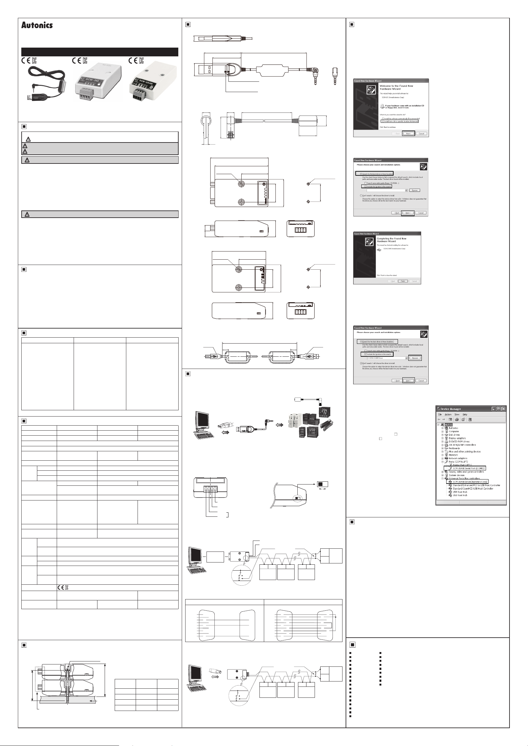
Dimensions
1. SCM-US
8
4 5
52
40.3
□
12
18
□
A.C.C (green LED)
: Rx/Tx Data Transmission
O P.R (red LED)
: Power
●
EXT-US (converter cable, sold separately)
8 8
8
23 5
4 9
2. SCM-38I
81.7
75.5
2-Ø3.3
7 88.6
'------------"E(
_;J-------"'-----m
3. SCM-US48I
75.5
2-Ø3 3
●
USB 2.0 AB type cable (accessory)
USB 2 0 AB type cable is enclosed and also sold separately.(Model: USB AB CABLE)
※
USB B
Type
Connection and Installation
00
±5
20
38
1. SCM-US
USB 2.0
A Type (male)
1
※
USB
SCM-US
Computer
※Use only for Autonics/Konics products that support SCM-US.
1: Some products requires the dedicated converter cable(EXT-US, sold separately) to connect SCM-
※
US. Do not apply excessive force to the converter cable. t may cause damage to the unit. Do not
bend cable and connector part. t may cause damage to the unit.
2. SCM-38I
A B V G
G: GROUND
V: 12-24VDC input
B(-)
RS485 signal line
J
When wiring the RS485 connector, use AWG 24 cable and tighten the connector screw with a
※
tightening torque of 0.22 to 0.4N.m with the screwdriver for M2 screw.
A(+)
● Multi-drop connection method with PC
RS232C RS485
R×D-R×D
T×D-T×D
GND-GND
RS232C Cable
Computer
B(-)
ON OFF
A(+)
● RS232C cable connection
Standard connection Using Auto-loop Back
Computer
DCD
① ①
DSR
⑥
RXD
② ②
RTS
⑦ ⑦
TXD
③ ③
CTS
⑧ ⑧
DTR
④
⑨ ⑨
RI
GND
⑤
When the software of the communication driver uses Auto-loop Back, please connect as the above.
※
SCM-38I
⑥
④
⑤
3. SCM-US48I
USB 2.0
B Type (male)
Computer
When wiring the RS485 connector, use AWG 24 cable and tighten the connector screw with a
※
tightening torque of 0.22 to 0.4N.m with the screwdriver for M2 screw.
USB RS485
B(-)
ON OFF
A(+)
1500
200
38
38.8
25.6
23.2
I
~
25.6
38.8
23.2
±30
1,000
20
Serial
Autonics and KONICS products
which support the PC loader port
● Terminating resistance selection
ON: Using terminating resistance
OFF: Not using terminating resistance
GND
VCC
Terminating
(12-24VDC)
resistance
(100 to 120Ω)
A(+) B(-) A(+) B(-)
A(+) B(-)
RS485
#1
RS485
#1
DCD
DSR
RXD
TXD
CTS
DTR
GND
RTS
RI
RS485
DEVICE
#2
Computer
①
⑥
②
⑦
③
⑧
④
⑨
⑤
Terminating
resistance
(100 to 120Ω)
RS485
DEVICE
#2
DEVICE
A(+) B(-) A(+) B(-) A(+) B(-)
DEVICE
19.7
TI
● Panel cut-out
● Panel cut-out
±5
EXT-US
(converter cable,
sold separately)
RS485
...
DEVICE
#30
RS485
DEVICE
#30
(unit: mm)
Ø11.5
2-M3 TAP
25.6
2-M3 TAP
25.6
USB A
Type
1
※
ON OFF
Terminating resistance
selection switch
B(-)
RS485
DEVICE
#31
A(+)
SCM-38I
①
⑥
②
⑦
③
⑧
④
⑨
⑤
B(-)
RS485
DEVICE
#31
A(+)
Driver Installation (SCM-US, SCM-US48I)
This Driver Installation shows the procedure for Windows XP. There might be some differences in the
※
specication above depending on OS.
1. USB Driver Installation
1) Visit our website to download 'SCM-US USB Driver' or 'SCM-US48I USB
2) Unzip download 'SCM-US.zip' or 'SCM-US48I.zip' at any directory.
3) When connecting product with USB port, 'Found New Hardware Wizard" will appear automatically.
'Do you want to search software by connecting 'Window Update'?. Click 'No' button and the following
window will be displayed to proceed Driver installation. Select 'Install from a list or specic location
(Advanced)' and click 'Next'.
Welcome
to
the
Found
New
Wizard
Hardware
Tf., ...,.,..d.-...,,)'00,
rl<lal:oflworelor
whotdoJ,'OU w«li
tho..,..dtodo?
O imt
althedlwa1eoctanot
option,.
be,t,i"""lw,d
-ROM
l
Ye1lroma§t
l
<aod:.JJ~ j~
the
Found New
5"!:::fRecommended )
o,.-,
;.;Q<ot,on
deldoearch,
whdinwdo,bcal
wlbomtaled
I
w...,,,,,,, doe,0011J,01or!oetMI:
V,.dvo,,cod
)j
~
j 0 t.,toll«rno ~
4) Select 'Search for best driver in these locations' and 'include this location in the search' continuously.
Click the 'Browse' button.
5) When 'Browse Folder' window is displayed, select 'SCM-US\Driver' and click 'Finish'. Click 'Next' to
proceed with the USB Driver installation.
Plc
ue
clloo1e y
o~, o«oc
t,
ond in, tollOlion
©
§e,,chlor
thebe>ldn,,«in the,eOCa!ioo, I
U
..
thochod..,,,,..,bobwiolirrtor_,.lho
palti,..-.:j rem;,,.t,lome<ia
i 0
Q
l)_on
O>o<,:etn,ow,nu,..+oe
llledov«youcCOO,o M be theOMmaol:chlorycuha<O...,e
6) Hardware installation message will appear while Found New Hardware Wizard is running.
Click 'Continue Anyway' to proceed with installation.
7) The following window will be displayed if the USB Driver is installed properly. Click the 'Finish' button.
If USB port is changed, reinstall the USB driver.
※
0 Seorch,..,.,,..able
1,
d..de,ri,~OOintoe,..,,m
he.,,rch.l
wlchoo,
Completing
Hardware Wiza rd
The
mMa(l'opl)y,CTl
o thedrrttftoOOol
1thedo11<edu
Driver'.
2. Serial Port Driver Installation
1) After installing USB Driver, Serial Port (COM port), 'Found New Hardware Wizard' will appear (Serial
Port Driver installation follows the same procedures described in installing USB Driver).
2) After selecting 'Install from a list or specic location(advance)', click 'Next' button.
The following window will be displayed for 'Search and installation options'
3) Because a driver location was selected when installing USB driver, click 'Next' button.
Pleasochoo
sel"""••aochandin<tallOlion
0
5eooch
r,mcrv-rriecle(lom,.CORO!il
I 0 1
....,dolno~OOin
~j
{)'.IS_C>
_'°'-'°-""
Q l)_rnlsea<cltl wilct-.,o,
Chcme trll'opllonlo ,electthe
tO<<lrMe<l")'JchoooeMbethebectm>lchfor!<)'ihorct..ore
the
....
---~l
ethedfr,.
« to
do¥>0edrM!<~omoi>1
clr I
01"""-
opion,
.. J
v"II
BJC#fff
. W
indow,doe,no1!1""arteelhat
11
4) Hardware installation message will appear while Found New Hardware Wizard is running.
Click 'Continue Anyway' to proceed with installation.
5) 'Completing the Found New Hardware wizard' will be displayed if the Serial Port Driver is installed
properly. Click the 'Finish' button.
Verify that drivers were installed properly with the
※
windows Device Manager after nishing USB Driver
and Serial Port Driver installation.
Open the folder [My computer], open the system
folder (click right), click the hardware tab, and click
the device manager button. Then, make sure that
'SCM-US Serial Port (COM
Serial Port (COM )' is found in 'Port (COM and
LPT)' and 'SCM-US Driver(Autonics Corp)' or 'SCMUS48I Driver(Autonics Corp)' is found in 'Common
Serial Bus Controller' category.
□
) ' or 'SCM-US48I
□
S Device Manager
Ei
le
B_ction
'i_ie
l/<i
t!elP
ttl Computer
!E
._,
Di!.kdrives
~---
i Display adapters
tt
h,!
~ 0\/0/CD-ROM drives
~ § IOEAT
A/A
TAP
(ti
IP
Keyboards
~. -
'('.)
Mice_
and
other
tt1
§
Monitor~
$ • Net"'10rk~dapters
El
;!J
Pgrts
(CO
M &
LPT
"'
"'
13
~PJl""'l!.:Wl""'-"lOW!!l"'-
USB
Root Hub
GJ[g)IK!
I controllers
pointir,. devices
)
--,
Caution during Use
1. Follow instructions in 'Cautions during Use'. Otherwise, it may cause unexpected accidents.
2. 12-24VDC power supply should be insulated and limited voltage/current or Class 2, SELV power
supply device.
3. Use only designated connector and do not apply excessive power when connecting or disconnecting
the connectors.
4. Keep away from high voltage lines or power lines to prevent inductive noise.
In case installing power line and input signal line closely, use line lter or varistor at power line and
shielded wire at input signal line.
Do not use near the equipment which generates strong magnetic force or high frequency noise.
5. Do not connect or disconnect the USB cable, earphone jack, or RS485 cable quickly and repeatedly
while communicating.
t may cause damage or malfunction of the product and PC.
6. After supplying power, connect with the communication output product. When disconnect,
communication output product rst and power last.
7. When connecting multiple SCM-US or SCM-US48I units to a PC, number of COM port goes up in
sequential order and it takes some time to identify and assign number of COM port.
8. When connecting the RS485 communication output product, connect the terminating resistance (100
to 120Ω) at each end of the communication cable.
9. Use twist pair wire for RS485 communication. If not, use A(+) and B(-) cables in the same length.
10. Use USB cable of designated standard, and do not use extension cable.
11. This unit may be used in the following environments.
Indoors (in the environment condition rated in 'Specications')
①
Altitude max. 2,000m
②
Pollution degree 2
③
Installation category I
④
Major Products
00
Photoelectric Sensors Temperature Controllers
Fiber Optic Sensors Temperature/Humidity Transducers
Door Sensors SSRs/Power Contro lers
Door Side Sensors Counters
Area Sensors Timers
Proximity Sensors Panel Meters
Pressure Sensors Tachometers/Pulse(Rate)Meters
Rotary Encoders Display Units
Connectors/Sockets Sensor Controllers
Switching Mode Power Supplies
Control Switches/Lamps/Buzzers
I/O Terminal Blocks & Cables
Stepper Motors/Drivers/Motion Controllers
Graphic/Logic Panels
Field Network Devices
Laser Marking System(Fiber, CO₂, Nd:YAG)
Laser Welding/Cutting System
■
■
■
■
■
■
■
■
■
DRW160897AC
 Loading...