

Autonics ROTARY ACTUATOR TYPE 5-PHASE STEPPER MOTOR Instruction Manual
DRW170419AB
Autonics
ROTARY ACTUATOR TYPE
5-PHASE STEPPER MOTOR
I N S T R U C T I O N M A N U A L
CE
Rotary actuator type Rotary actuator+
Thank you for choosing our Autonics product.
Please read the following safety considerations before use.
Safety Considerations
Please observe all safety considerations for safe and proper product operation to avoid
※
hazards.
symbol represents caution due to special circumstances in which hazards may occur.
※
Failure to follow these instructions may result in serious injury or death.
Warning
Caution
Warning
1. Fail-safe device must be installed when using the unit with machinery that may
cause serious injury or substantial economic loss. (e.g. nuclear power control,
medical equipment, ships, vehicles, railways, aircraft, combustion apparatus, safety
equipment, crime/disaster prevention devices, etc.)
Failure to follow this instruction may result in re, personal injury, or economic loss.
2. Do not use the brake for safety.
Failure to follow this instruction may result in personal injury, or product and ambient
equipment damage.
3. Fix the unit on the metal plate.
Failure to follow this instruction may result in personal injury, or product and ambient
equipment damage.
4. Do not connect, repair, or inspect the unit while connected to a power source.
Failure to follow this instruction may result in re.
5. Install the unit after considering counter plan against power failure.
Failure to follow this instruction may result in personal injury, or economic loss.
6. Check 'Connections' before wiring.
Failure to follow this instruction may result in re.
7. Do not disassemble or modify the unit.
Failure to follow this instruction may result in electric shock or re.
8. Install the motor in the housing or ground it.
Failure to follow this instruction may result in electronic shock, re, or personal injury.
9. Make sure to install covers on motor rotating components.
Failure to follow this instruction may result in personal injury.
10. Do not touch the unit during or after operation for a while.
Failure to follow this instruction may result in burn due to high temperature of the surface.
11. Turn OFF the power directly when error occurs.
Failure to follow this instruction may result in electric shock, re, or personal injury.
Caution
1. Use the unit within the rated specications.
Failure to follow this instruction may result in re or product damage.
2. Use dry cloth to clean the unit, and do not use water or organic solvent.
Failure to follow this instruction may result in re.
3. Do not use the unit in the place where ammable/explosive/corrosive gas, humidity,
direct sunlight, radiant heat, vibration, impact, or salinity may be present.
Failure to follow this instruction may result in re or explosion.
4. The motor may overheat depending on the environment.
Install the unit at the well-ventilated environment and forced cooling with a cooling fan.
Failure to follow this instruction may result in product damage and degrada ion.
The above specications are subject to change and some models may be discontinued
※
without notice.
Be sure to follow cautions written in the instruction manual and the technical descriptions
※
(catalog, homepage).
Failure to follow these instructions may result in personal injury or product damage.
built-in brake type
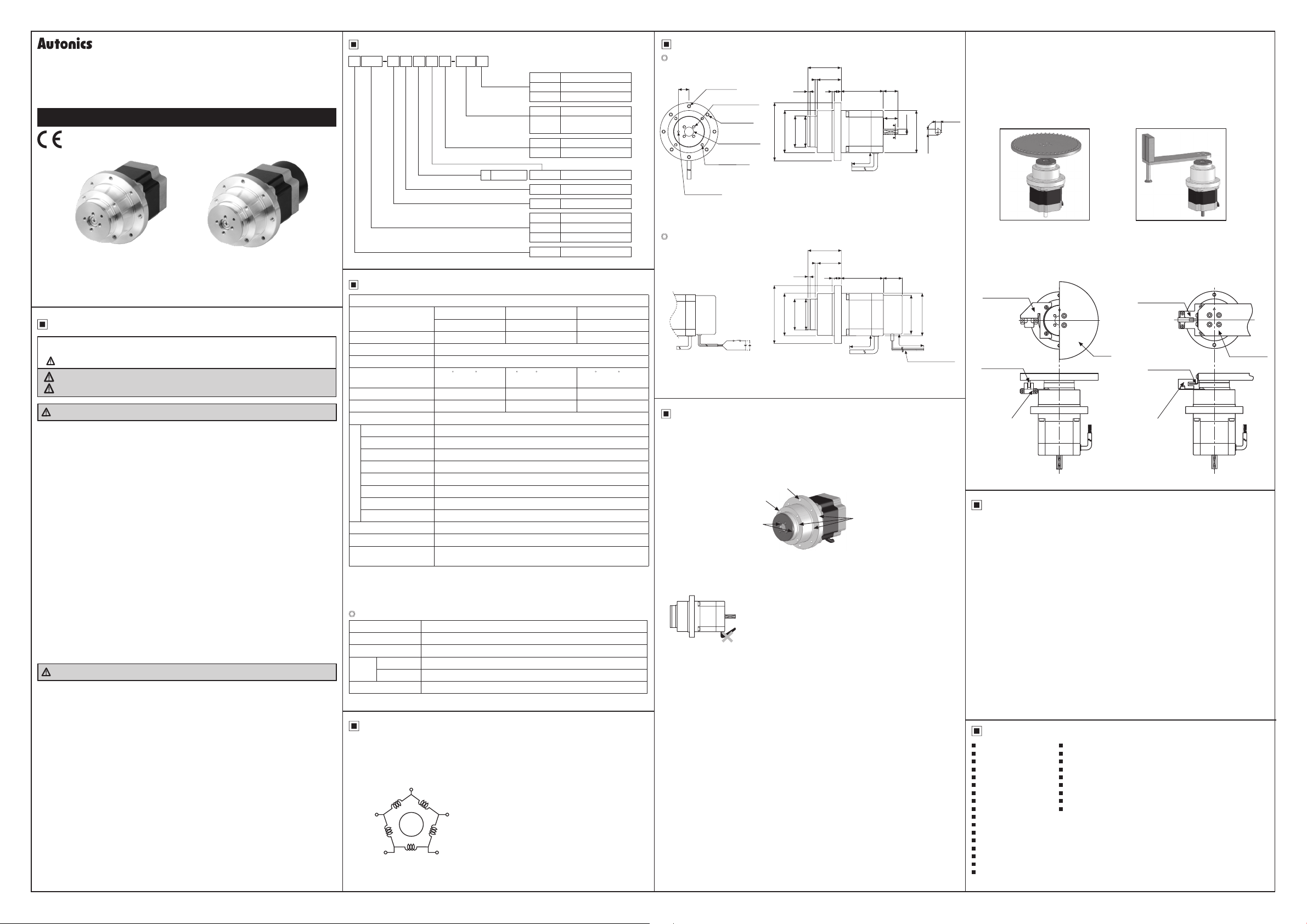
Ordering Information
Shaft type
5
Gear ratio
Motor type
6 60×60mm
5 1:5
7.2 1:7.2
10 1:10
R Rotary actuator type
Rotary actuator+
※
1
RB
built-in brake type
No mark Single shaft
W Dual shaft
6 59.5mm
5 5-phase
M 1.4A/Phase
35K 35kgf.cm
40K 40kgf.cm
50K 50kgf.cm
A Autonics motor
A
35K
MRB6
Rated current
Max. holding torque
tem
※
1: Built-in brake type provides single shaft type only.
5
Motor frame size
Motor phase
6
W
Motor length
Specications
Frame size 60mm
Model
Max. holding torque
Rotor moment of inertia
Rated current 1.4 A/Phase
Basic step angle
Gear ratio 1:5 1:7 2 1:10
Allowable speed range 0 to 360rpm 0 to 250rpm 0 to 180rpm
Backlash [min] ±20' (0.33 )
Rated excitation voltage 24VDCᜡ ±10%
Rated excitation current 0.33A
Static friction torque 8kgf.cm
Rotation part inertia 29×10
Insulation class B type (130℃)
B type brake Power on: brake is released, power off: brake is operating
Operating time Max. 20ms
Electro-Magnetic Brake
Releasing time Max. 25ms
Absolute position error ±20' (0.33 )
Lost motion ±25' (0.33 )
※
3
Weight
※
1: Max. holding torque is maintenance torque in stopping the motor when supply the rated current
and is standard method for comparing the performance of motors.
※
2: Moment of rotor inertia indicates a part, except Gear Head part.
※
3:
The weight includes packaging. The weight in parenthesis is for unit only.
g
Common specications
Insulation class B type (130℃)
Insulation resistance Over 100MΩ (at 500VDC megger) between motor coil-case
Dielectric strength 1 kVAC 50/60Hz for 1 min between motor coil-case
Ambient temp.
Environ-
I
ment
Ambient humi.
I
Protection structure IP30 (IEC34-5 standard)
※
Environment resistance is rated at no freezing or condensation.
A35K-M566(W)-R5 A40K-M566(W)-R7.2 A50K-M566(W)-R10
A35K-M566-RB5 A40K-M566-RB7.2 A50K-M566-RB10
※
1
35 kgf.cm (3.4 N.m) 40 kgf cm (3.9 N.m) 50 kgf cm (4.9 N.m)
2
※
280 g.cm2 (280x10-7 kg.m2)
0.144
/ 0 072
(Full/Half step)
-7
kg.cm
·Rotary actuator type: approx. 1.4kg (approx. 1 3kg)
·Rotary actuator+built-in brake type: approx. 1.7kg (approx. 1.6kg)
-10 to 50℃, storage: -25 to 85℃
35 to 85%RH, storage: 35 to 85%RH
2
0.1 / 0.05
(Full/Half step)
0 072 / 0 036
(Full/Half step)
Connection Diagram
Autonics 5-phase stepper motors use pentagon wiring methods.
Therefore, it is a proper product for the 5-phase stepper motor driver which is working as a bipolar
pentagon driving method.
The connections of each phase and each color of the lead-wire are as follows:
Blue
E Phase
Black
D Phase B Phase
Green
C Phase
A Phase
Orange
or Yellow
Red
Dimensions
AK-M566(W)-R
±0.01
R15
Ø3
DP 3
※
These dimensions are for dual shaft models.
Single shaft models do not include shafts indicated in the dotted lines.
g
AK-M566-RB
※
Built-in brake type provides single shaft type only.
□
4-M5 Hole
P.C.D. 72
4-M4 Tap DP 6
P.C D. 19
4-M4 Hole
P.C.D. 70
Ø13 Hole
DP 3.5
4-M4 Tap DP 8
P.C.D. 53
+0.01
Hole
0
□
0
-0.018
SW1
47.5
34
3
10
3
3.2
0
0
0
0
-0 035
-0.025
-0.025
+0.018
Ø82
Ø60
Ø43
Ø44
Ø5 0.6m
<Rotary actuator type>
47.5
3
34
3 2
0
0
0
+0.018
-0.025
-0 025
-0 035
Ø60
Ø82
Ø44
<Rotary actuator+built-in brake type>
10
3
0
Ø43
Ø5, 0 6m
59 5
59.5
±1
±1
21
±0.25
20
B
B'
±1
26.5
(unit: mm)
0
-0 015
Ø8
SectionedB-B'
Ø1.5, 0.6m
7 5
90°
60
□
±0.15
7.5
60
□
Ø55
Brake lea d wire
±0.15
Installation
1. Motor installation method
①Installtherotaryactuatoragainstthemetalpanelwhichhashighthermalconductivitysuchasironor
aluminumbecauseofvibrationandhearra
Mounting plates is required to have over 8mm of thickness.
As shown in the gure below
②
actuator. In case of using M4, screw tightening torque needs to be 2N.m, and in case of M5, 4.4N m.
Output flange
Do not apply excessive force on motor cable when installing rotary actuators. Do not forcibly pull or
③
insert the cable. Do not move the motor cable repeatedly with excessive force, or It may cause poor
connection or disconnection of the cable.
In case when frequent cable movement or excessive force is required, proper safety
countermeasures
2. Installation condition
Install the motor in a place that meets certain conditions specified below.
It may cause product damage if instructions are not following.
①
The inner housing installed indoor
(This unit is manufactured and designed for attaching to equipment. Install a ventilation device.)
②
Within -10 to 50
③
Within 35 to 85%RH (at non-dew status) of ambient humidity
④
The place without explosive, flammable and corrosive gas
⑤
The place without direct ray of light
⑥
The place where dust or metal scrap does not enter into the unit
⑦
The place without contact with water
⑧
The place without contact with strong alkali or acid material
⑨
The place where easy heat dissipation could be made
⑩
The place where no continuous vibration or severe shock
⑪
The place with less salt content
⑫
The place with less electronic noise occurs by welding machine, motor
⑬
The place where radioactive substances and magnetic fields does not exist and is not in the
vacuum status
must be ensured.
, total 4 mounting TAP holes on F1 and F2 are used to x rotary
F1 (M4)
in-low part
℃ (at non-freezing status) of ambient temperature
3. Installation of accessories (index table, arm, etc.)
Mount the accessory (index table or arm) on output axis ange using M4 screw.
①
Note that Ø13 in-low part is processed with C0.3. It is necessary to process the accessory under
2 to mount. Place a positioning pin on ange's positioning hole and push it in.
C0
Make sure not to place the pin on output ange.
Do not use a hammer to mount the accessory (table or arm). It may cause product damage.
②
Mount the accessory with hands in a gentle manner.
Make sure that accessory mounted on output axis to be xed as tight as possible.
③
It may cause an accident if an actuator is detached from the motor while driving.
diation of the motor.
F2 (M5)
Body in-low part
, oil, or other liquid
, etc.
4. Motor operation
Observe the rated product specication.
Do not apply rotational load on the motor while it stops.
①
Do not apply excessive load on the motor while driving. It may cause motors to miss a step.
②
Use a sensor for home searching or division completed position detecting.
③
5. Application
● Index Table
● Moving Arm
6. Sensor attachment
● Index Table
Sensor bracket
Detection Pin
Photo micro sensor
Autonics
BS5 - L2M
Table
● Moving Arm
Sensor bracket
Detection Pin
Photo micro sensor
Autonics
BS5 - T2M
Moving Arm
Cautions during Use
1. Follow instructions in 'Cautions during Use'.
O herwise, It may cause unexpected accidents.
2. Using motors at low temperature may cause reducing ball bearing's grease consistency and
friction torque is increased.
Start the motor in a steady manner since motor's torque is not to be influenced.
3. When power is supplied or not to the brake, the unit may occur clack sound.
4. When drive the motor
, supply power to electro-magnetic brake for releasing the brake.
When the brake pad is worn out, the product life cycle is shorten, the rated static friction
torque is reduced.
5. For using motor, it is recommended to maintenance and inspection regularly.
Unwinding bolts and connection parts for the unit installa
①
Strange sound from ball bearing of he unit
②
Damage and stress of lead cable of the unit
③
Connection error with driver
④
Inconsistency between he axis of motor output and the center, concentric (eccentric,
⑤
ion and load connec ion
declination) of the load, etc.
6. This unit may be used in the following environments.
Indoors (in
①
Altitude max. 2,000m
②
Pollution degree 2
③
Installa ion category II
④
he environment condi ion rated in 'Specifications')
Major Products
Photoelectric Sensors Temperature Controllers
Fiber Optic Sensors Temperature/Humidity Transducers
Door Sensors SSRs/Power Controllers
Door Side Sensors Counters
Area Sensors Timers
Proximity Sensors Panel Meters
Pressure Sensors Tachometer/Pulse (Rate) Meters
Rotary Encoders Display Units
Connector/Sockets Sensor Controllers
Switching Mode Power Supplies
Control Switches/Lamps/Buzzers
I/O Terminal Blocks & Cables
Stepper Motors/Drivers/Motion Controllers
Graphic/Logic Panels
Field Network Devices
Laser Marking System (Fiber, CO₂, Nd: YAG)
Laser Welding/Cutting System
■
■
■
■
■
■
■
■
■
DR W170 419AB
 Loading...