

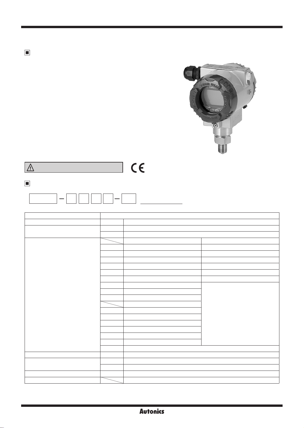
Display Type Pressure Transmitters
Features
•
Minimized disturbance eect by improving noise
resistance
•
Excellent corrosion resistance with stainless steel
housing
•
High accuracy ±0.3% F.S.
•
Various functions
- User input range, display scale, output scale, digital
lter, multi display selection, abnormal operation
display, TUF (Two Unit Function), etc.
•
Explosion-proof specication: Ex D IIC T6
•
Protection structure: IP67 (IEC standard)
•
Applications
- Indoor heating, water supply and sewage, and
incinerator and small and medium sized projects
Please read “Safety Considerations”
in the instruction manual before using.
.___l&
____
Ordering Information
~I
CE:
PTF30 Series
~I-DD
① ② ③ ④
①Item
②Measurement pressure
③Rated pressure range
G 7 N N F8PTF30
□□-□
⑤
Description
PTF30 Display Type Pressure Transmitters
G Gauge pressure, sealed gauge pressure
A Absolute pressure
---.........___
1 0 to 35kPa 0 to 35kPa
2 0 to 0.1MPa 0 to 0.1MPa
3 0 to 0.2MPa 0 to 0.2MPa
4 0 to 0.7MPa 0 to 0.7MPa
5 0 to 2MPa 0 to 2MPa
6 0 to 3.5MPa 0 to 3.5MPa
7 0 to 7MPa
8 0 to 21MPa
9 0 to 35MPa
--.............
A -35 to 0kPa
C -0.1 to 0MPa
F -0.1 to 0.2MPa
H -0.1 to 0.7MPa
M -0.1 to 2MPa
O -0.1 to 3.5MPa
Z Others
communication output
④HART
⑤Mounting bracket
⑥Pressure port
⑦User pressure range
※
1: The pressure is sealed gauge pressure. The unit is sealed structure. It is based on atmospheric pressure 101.3kPa (1.013bar).
※
2: Write the desired pressure range and it is the default of user pressure range.(select "Z" at ③Rated pressure range)
N None
N Without bracket
B With bracket
F8 G3/8 (PF)
----------
(-0.1 to 35MPa)
__
⑥ ⑦
※1
Gauge pressure Absolute pressure
Sealed gauge pressure
User pressure range
※1
-
※2
Autonics
G-75
PTF30 Series
Specifications
Series PTF30
Measured materials Vapor, liquid, uid (except corrosive environment of stainless steel 316)
Power supply 15-35VDCᜡ
Display method 12-segment 4-digit LCD Display
Character size W6.24×H10.73mm (12-segment) / W1.45×H2.5mm (unit)
Output DC4-20mA 2-wire Low-limit: 3.6mA (-2.5%), high-limit: 21.6mA (+10%)
Accuracy
Temperature characteristics At 20℃, ± (0.075% × URL + 0.15% × Span)
Setting method Setting by front push keys
Sampling cycle 300ms
Dielectric resistance 1,000VAC for 1 min (between external terminal and case)
Vibration 0.75mm amplitude at frequency of 5 to 55Hz (for 1 min) in each X, Y, Z direction for 2 hours
Insulation resistance Over 100MΩ (at 500VDC megger)
Noise immunity Square shaped noise by noise simulator (pulse width 1μs) ±240V
Memory protection Approx. 10 years (non-volatile semiconductor memory type)
Environ-
ment
Material
Explosion class
Protection structure IP67 (IEC standard)
Approval
Unit weight Approx. 1.2kg
※
※
※
※
1
Ambient temperature -20 to 70℃, storage: -20 to 80℃
I
Ambient humidity 0 to 85%RH
I
※
2
1:
F.S.: Rated pressure range.
2: This Explosion class is acquired and managed by Konics Co., Ltd.
Environment resistance is rated at no freezing or condensation.
±0.3% of F.S.
Body: aluminum (AlDc.8S), cover O-Ring: buna N,
diaphragm: stainless steel 316, connections: stainless steel 316
Ex d IIC T6
ᜢ
Pressure Conversion Chart
2
gf/cm
2
1gf/cm
---------------
1kgf/cm
1Pa 0.010197 0.0000102 1 0 001000 0.000001 0.01 0.000010 0.101972 0.000145 0.007501
1kPa 10.19716 0.010197 1000.000 1 0.001000 10 0.010000 101.9716 0.145038 7.500617
1MPa 10197.16 10.19716 1000000 1000.000 1 10000 10.00000 101971.6 145.0378 7500.617
1mbar 1.019716 0.0010197 100.0000 0.100000 0.000100 1 0.001000 10.19716 0.014504 0.750062
1bar 1019.716 1.019716 100000.0 100.0000 0.100000 1000 1 10197.16 14.50377 750.0617
1mmH2O 0.100000 0.000100 9.80665 0 009807 0.0000098 0.0980665 0.000098 1 0.001422 0.073556
1psi 70.30699 0.070307 6894.757 6 894757 0.006895 68.94757 0.068948 703.0696 1 51.71493
1mmHg 1.359510 0.001360 133.3224 0.133322 0.0001333 1.333224 0.001333 13.59510 0.019337 1
1 0.001000 98.0665 0 0980665 0.000098 0.980665 0.000981 10.00000 0.014223 0.735559
2
1000.000 1 98066.50 98.06650 0.098067 980.665 0.980665 10000.00 14.22334 735.5592
kgf/cm2Pa kPa MPa mbar bar mmH2O psi mmHg
G-76
Autonics
Display Type Pressure Transmitters
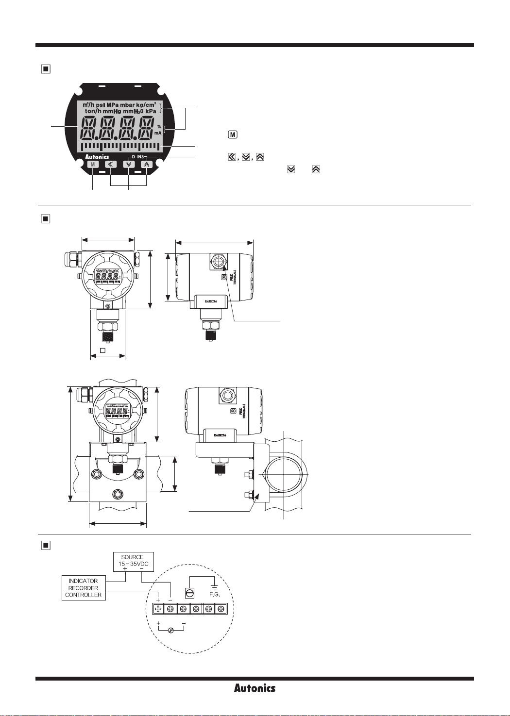
Unit Descriptions
①
④ ⑤
Dimensions
~
83
g H
h
a
55
□
►
1
①
Display part
: Displays detected pressure value, several setting value and errors.
②
Unit display part: Displays the currently set input unit.
②
③
Output scale bar graph
: Displays output DC4-20mA as scale bar graph by 5% unit.
④
key: Used to enter parameter mode, move parameters and save
③
⑥
96
Ø83
SV.
⑤
⑥
D.IN3: Press the
function (display HOLD, zero-point adjustment) at
parameter.
128
key: Used to enter parameter set mode, move digits.
and keys at the same time for 3 sec, the set
2-1/2-14(NPT)
DI K
(unit: mm)
in
● Mounting bracket
m
200
Connections
ci{i:~~~R
f------+/~//
94
a
96
DN50
J
.I
,'
+ - 1
i
IH1•ll@ll@ll©ll@ll@II;
I J
1 2 3 4 5 6
I J
\ + - I
Ampere
\,~
meter
........
a
~
11
(2B Pipe)
Mounting bracket
n-_,\',
,,-'/
.,,,""
※
You can check DC4-20mA output by connecting an
ampere meter. (impedance: max. 30Ω)
Autonics
G-77

PTF30 Series
Functions
Input unit [ ]
You can select input unit.
(bar, mbar, Pa, kPa, MPa, gf/cm
mmHg, %, OFF)
User input range [
■
Even though each unit has the range, you can set user
input range within the pressure range when input range
is limited for actual usage.
Decimal point setting [ ]
■
This function is to change decimal point digit for input
display value.
When input unit is set as % [
the display position of decimal point is moved.
• Setting range: 0 / 0.0 / 0.00 / 0.000
※
Setting range is dierent by the pressure range.
Display scale [ , ]
■
This function is to set (-1999 to 9999) for particular high/
low limit value in order to display high/low limit value of
measurement input. If measurement inputs are ‘a’ and ‘b’
and particular values are ‘A’ and ‘B’, it will display a=A,
b=B as below graphs.
Display
Input
2
, kgf/cm2, mmH2O, psi,
,
]
] or OFF [
?/O
Display
B
A
---------
a i
---
OFF
'
b
], only
Input
~
Display
'
Input
b
※
This function is available only when input unit is
% [
] or OFF [
?/O
Zero-point correction [
■
It corrects the error of display value for 0% input.
• Setting range: -999 to 999
Output
0.00kgf/cm
Slope correction [
It corrects the error of display value for 100% input.
• Setting range: 0.900 to 1.100
Output
OFF
2
].
E
10.00kgf/cm
]
]
Input
2
Output scale [
■
, ]
For DC4-20mA current output, this function is set to
display value for current output.
Set the display value for DC4mA [
value for DC20mA [
Output
21.6 mA
t-------
20
mA
t-----,r
4 mA
---
3.6
mA
w:~i~-~'-'-•
lOUT hOUT
Digital filter [
■
hOUT
].
]
Output
21.6 mA ,
20mA
3.6 mA
Input
] and the display
lOUT
-1--,
4 mA
_J __
,_I
___
-j--,-i
--~·_,,__
lOUT hOUT
.,,.
Input
Digital lter is able to display stably and output the noise
from input line and irregular signals. This unit applies
moving average digital lter and display cycle is same.
• Setting range: 01 to 16
※
When setting as 01, digital lter function does not run.
Digital input [
■
]
By front keys operation (D.IN3: + for 3 sec), one of two
functions executes as the below table.
Function Operation
Display
HOLD
Hold
Zero-point
Z-TM
adjustment
Multi-display selection [
■
Select one for display 1 and display 2 among PV,
lPEK, hPEK
displays two dierent values in turn for 2 sec.
selecting
lPEK
Temporarily indicated value is
stopped in order to conrm indicated
value in unstable input.
It is same function as [
executing this function, you can
check and change correction value at
.
ZERO
and
. Set
DSP1
(
hPEK), the left (or the right) of output
DSP2
ZERO
, ]
dierently and it
]. When
OUT
When
,
scale bar graph ashes for 0.5 sec.
High/Low peak monitoring [
■
, ]
This function is to save high/low peak to check the
invisible abnormal condition of system. Select this
function display selection [
dSP1, dSP2
] parameter.
When the high/low peak is out of the temperature range,
it displays
To initialize high/low peak, press the
same time for 3 sec at [
HHHH
or
LLLL
.
hPEK
] or [
+ keys at the
].
lPEK
In this case, peak value is the present input value.
G-78
0.00kgf/cm
2
Input
10.00kgf/cm
2
Autonics

Display Type Pressure Transmitters
Functions
Two unit function [
For compound pressure model, this function displays the
input pressure which is below atmospheric pressure by
mmHg unit. It displays the input pressure atmospheric
pressure or over atmospheric pressure by the set
pressure unit.
Display
2
(kgf/cm
6.00
4.00 ----· kg/cm
-1.03!
mmHg!
UNIT
Lock [
It limits to check parameter set value and to change it.
Parameter
: Enable to check/set, : Enable to check, disable to set,
•
: Disable to check
0
In LOc 2, only the LOCK parameter displays.
]
OFF LO c1 LOc 2
0
]
)
---------------------
u
4.00 6.00 (kgf/cm
-760mmHg
2
Input
2
)
Parameter initialization [
■
To initialize all parameter as factory default, supply the
power to the product with pressing the
at the same time and it enters initialization parameter.
Supply the power with pressing the
[Ml
+ keys at the same time.
,
]
1-
[Ml
key and
1
key
CLR
[Ml
NO
[al
M
YES
i[Ml
Completes ini ialization.
Error
■
Display Descriptions Troubleshooting
Flashes when measured
pressure is higher than the
HHHH
'pressure range'.
Flashes when measured
pressure is lower than the
LLLL
'pressure range’.
Flashes when there is error to
ERR
SV
Adjust measured
pressure within
the 'pressure
range'.
Re-set it after
checking
the setting
conditions
Factory Default
Parameter Default Parameter Default Parameter Default Parameter Default
※
UNIT BAR L-SC 00)0 lOUT )000 DSP1 PV
※
L-RG )000 H-SC 10)0 hOUT )350 DSP2 PV
H-RG )350 ZERO 000 MAvF 04 TUF OFF
dP )350 SPAN !000 DI-K HOLD LOCK OFF
※
Defaults are dierent by the pressure range by each model.
1:
1
※
1
※
1
1
※
1
Autonics
G-79

PTF30 Series
Parameters
~
※
1. S: Press any key among the .
※
I{<]
2.
: Moves digits /
-
※
3. Press the
The value ashes twice and is saved. It moves to next parameter.
※
4. Defaults are dierent by the pressure range by each model.
※
After entering setting group, press the
※
: This parameter may or may not appear, depending on the other parameter set.
~-
-
--
□
.
RUN mode
~~
M
key after checking/changing SV in each parameter.
,
: changes SV.
[{<],~.~
M
key for 3 sec or there is no additional key operation in 30 sec, it returns to RUN mode.
□
ioo
Input unit
UNIT BAR
r
Low-limit input value
※
4
L-RG ----
S
•
+
S
•
loo
High-limit input value
※
4
H-RG ----
S
•
ioo
Decimal point
posi ion
※
4
Low-limit scale value
dP ----
L-SC 00)0
High-limit scale value
.......................
. .
H-SC 10)0
i
.........
ioo
..
...:
S
S
S
-
※
1
►
►
►
►
I
I
I
I
※
2
100
BAR PA
※
3
• Setting range: Within the pressure range of input type
• Setting range: Within the pressure range of input type
Select the decimal point position of display scale value.
※
Setting range is dierent by the pressure range.
)0 )000)00 0
• Setting range: -1999 to 9999
※
Displayed only when selecting input unit [
• Setting range: -1999 to 9999
※
Displayed only when selecting input unit [
mBAR KPA MPA gCM
UNIT
UNIT
] as % [
] as % [
mmH2PSImmHG?/OOFF
?/O
?/O
] or OFF [
] or OFF [
KgCM
OFF
OFF
].
].
G-80
Zero-point correction
ZERO 000
S
-
loo
Slope correction
SPAN !000
S
-
loo
Low-limit output
scale value
※
4
lOUT ----
S
-
ioo
High-limit output
scale value
※
4
hOUT ----
ioo
S
-
►
I
►
I
►
I
►
I
Corrects occurring error at 0% input.
• Setting range: -999 to 999
Corrects occurring error at 100% input.
• Setting range: 0.900 to 1.100
• Setting range: Within temperature range when input unit is standard pressure unit.
Setting range: Within temperature range when input unit is standard pressure unit.
•
Within display scale range when input unit is % or OFF.
Within display scale range when input unit is % or OFF.

Moving average
digital lters
MAvF 04
S
•
►
I
Joo
Digital input
DI-K HOLD
S
•
►
I
Display Type Pressure Transmitters
Set the number of moving average digital lters.
• Setting range: 01 to 16
Select digital input function by front keys.
※
Press the
executes the selected function.
keys for 3 sec at the same time and it
4, 3
Z-TMHOLD
~
~ ~
1.-..1
OUTPV hPEKlPEK
~ ~
1.-..1
~
1.-..1
~
r
Display 1 selection
DSP1 PV
S
•
►
~I
I
ioo
Display 2 selection
DSP2 PV
I I •
S
►
I
I 1
..
:
►
OUTPV hPEKlPEK
I 1
..
:
►
I 1
..
:
►
~I-~
100
,--------•-------------------------------------------------------------------------------------------------,
Two Unit Function
'
r---~
i I I •
:
i--------i-------------------------------------------------------------------------------------------------i
TUF OFF
100
Lock
LOCK OFF
00
S
S
-
~-~
•I
I I I
..
~•
ONOFF
I I i
~
LOc1OFF LOc2
Proper Usage
Follow instructions in 'Cautions during Use'. Otherwise, It may cause unexpected accidents.
•
15-35VDC power supply should be insulated and limited voltage/current or Class 2, SELV power supply device.
•
The connection of this unit should be separated from the power line and high voltage line in order to prevent inductive noise.
•
Do not use this unit near the high frequency instruments
•
Switch or circuit breaker for suppling or cutting o the power should be installed nearby users for convenient control.
•
Use veried explosion-proof cable gland or sealing tting.
•
(explosion proof standard: over Ex d IIC T6, IP rating: over IP67 protection structure).
Use dedicated external terminal for earth. For connecting earth, use a spring washer and earth cable which is over 4mm².
•
This unit may be used in the following environments.
•
① Indoor / Outdoor (in the environment condition rated in 'Specications')
② Altitude max. 2,000 m
③ Pollution Degree 2
④ Installation Category II
※ The explosion-proof unit is certied and the same specications which is reported to Korea Gas Safety Corporation.
(This unit is manufactured following by the announcement 2013-54 of Ministry of Employment and Labor of Korea.)
※
Displayed only for compound pressure model
'
:
G-81
 Loading...