

Autonics PTF30 SERIES Instruction Manual
DRW171431AC
Specications
Autonics
Display Pressure Transmitter
PTF30 SERIES
I N S T R U C T I O N M A N U A L
Please read the following safety considerations before use.
Safety Considerations
00
Please observe all safety considerations for safe and proper product operation to avoid
※
hazards.
symbol represents caution due to special circumstances in which hazards may occur.
※
Warning
~1
*
~&.~===========================;1
Warning
1.Fail-safe device must be installed when using the unit with machinery that may
cause serious injury or substantial economic loss. (e.g. nuclear power control,
medical equipment, ships, vehicles, railways, aircraft, combustion apparatus, safety
equipment, crime/disaster prevention devices, etc.)
Failure to follow this instruction may result in personal injury, re or economic loss.
2.Do not use the unit in the place where ammable/explosive/corrosive gas, high
humidity, direct sunlight, radiant heat, vibration, impact, or salinity may be present.
Failure to follow this instruction may result in explosion or re.
3.The explosion-proof standard of this unit is Ex d IIC T6, protection structure of this
unit is IP67 and the range of max. surface temperature is below 85℃.
4.Do not disassemble or modify the unit.
Failure to follow this instruction may result in re or electric shock.
Caution
~&.L_
1.Do not apply beyond the rated pressure.
Failure to follow this instruction may result in product damage.
2.Use the unit within the rated specifications.
Failure to follow this instruction may result in fire or product damage.
3.Keep metal chip, dust, and wire residue from flowing into the unit.
Failure to follow this instruction may result in fire or product damage.
4.Check the polarity of the contact before wiring the unit.
Failure to follow this instruction may result in product damage by a fire.
5.This product is designed to detect the pressure of noncorrosive fluid. Do not use for
corrosive fluid.
Failure to follow this instruction may result in product damage.
6.Use a dry cloth to clean the unit, and do not use water or organic solvent.
Failure to follow this instruction may result in fire.
Ordering Information
00
PTF30
CJ-
① ② ③ ④ ⑤ ⑥ ⑦
①Item
~----f-f-
②Measurement
pressure
③Rated pressure range
④HART
communication output
⑤Mounting bracket
⑥Pressure port
⑦User pressure range
※
1: The pressure is sealed gauge pressure. The unit is sealed structure.
It is based on atmospheric pressure 101.3kPa (1.013bar).
※
2: Write he desired pressure range and it is the default of user pressure range.
(select "Z" at ③Rated pressure range)
Unit Descriptions
00
J
1
I
Dimensions
00
96
● Mounting bracket
Failure to follow these instructions may result in personal injury or product damage.
Caution
_____________
G
□□□□-□--
rrt/h
i,si
11Pa
mbar
ton/hmm
Hg mmH20
Iii/
Iii/
Iii/
/lil./lil./lil./lil
1111111111
p
11111
__.
M
•<
-v
I
------,--
4 5
~
Thank you for choosing Autonics product.
Failure to follow these instructions may result in serious injury or death.
---------ii
7 N N F8
kgfcm'
}
kP
■
0
Iii/
•
·•
Ill
I
,__
•
A...a,
83
h
a
55
g a
(-0.1 to 35MPa)
Description
PTF30 Pressure Transmitter
_-
--+-+_-_-_-
G Gauge pressure, sealed gauge pressure
A Absolute pressure
1 0 to 35kPa 0 to 35kPa
--------------
2 0 to 0.1MPa 0 to 0.1MPa
3 0 to 0. 2MPa 0 to 0.2MPa
4 0 to 0.7MPa 0 to 0.7MPa
5 0 to 2MPa 0 to 2MPa
6 0 to 3.5MPa 0 to 3.5MPa
7 0 to 7MPa
8 0 to 21MPa
9 0 to 35MPa
A -35 to 0kPa
---------
C -0.1 to 0MPa
F -0.1 to 0 2MPa
H -0.1 to 0.7MPa
M -0.1 to 2MPa
O -0.1 to 3 5MPa
Z Others
N None
N Without bracket
B With bracket
F8 G3/8 (PF)
---..________
1. Display part Displays detected pressure value,
2. Unit display part Displays the currently set input unit.
2
3. Output scale bar graph Displays output DC4-20 mA
4. key Used to enter parameter mode, move parameters
3
6
5. 1, 4, 3 key
6. D.IN3 Press the 4and 3keys at the same time for 3 sec,
_-_-_-_-_-_-_-_-_-_-_-_-_-_-
Gauge pressure Absolute pressure
sealed gauge pressure
User pressure range
several setting value and errors.
IMl
and save SV.
Used to enter parameter set mode, move digits.
the set function (display HOLD, zero-point adjustment)
at
DI K
-
Ø83
※1
-
※2
as scale bar graph by 5% unit.
in parameter.
128
~
j
Iii
II"""°''
~
11
~c--
2-1/2-14 (NPT)
※1
1i
~
li!J
96
.ii
(unit: mm)
~~1
200
~
)I~~]
\-
※
The above specications are subject to change and some models may be
discontinued without notice.
※
Be sure to follow cautions written in the instruction manual and the technical
descriptions (catalog, homepage).
I
..
~
0
94
------,
J
DN50
--HI
(2B Pipe)
...,..
•
Mounting bracket
-cl~~
Ire-:=:~
cl
r~~
00
;=_--------,-------------
Series PTF30
Measured materials Vapor, Liquid, Fluid (except corrosive environment of stainless steel 316)
Power supply 15-35VDCᜡ
Display method 12-segment 4-digit LCD Display
Character size W6 24×H10.73 mm (12-segment) / W1.45×H2.5 mm (unit)
Output
Accuracy
Temperature
characteristics
Setting method Setting by front push keys
Sampling cycle 300 ms
Dielectric resistance 1000 VAC for 1 min (between external terminal and case)
Vibration
Insulation resistance Over 100 MΩ (at 500VDC megger)
Noise immunity Square shaped noise by noise simulator (pulse width 1 ㎲) ±240 V
Memory protection Approx. 10 years (non-volatile semiconductor memory type)
~I-+----~
Environment
f-------_lJ
Material
Explosion class
Protection structure P67 ( EC standard)
Approval
Unit weight 1.2 kg
※
1:
F.S.: Rated pressure range.
※
2: The explosion class specification is acquired and managed by KONICS.
※
Environment resistance is rated at no freezing or condensation.
Functions
00
@
Input unit [
You can select input unit.
~I
(bar, mbar, Pa, kPa, MPa, gf/cm2, kgf/cm2, mmH2O, psi, mmHg, %, OFF)
@
User input range [
Even though each unit has the range, you can set user input range within the pressure range
when input range is limited for actual usage.
@
Decimal point setting [
This function is to change decimal point digit for input display value.
When input unit is set as % [
moved.
• Setting range: 0 / 0 0 / 0.00 / 0 000
※
Setting range is dierent by the pressure range.
@
Display scale [
This function is to set (-1999 to 9999) for particular high/low limit value in order to display
high/low limit value of measurement input. If measurement inputs are "a" and "b" and
particular values are "A" and "B", it will display a=A, b=B as below graphs.
Display Display Display
※
This function is available only when input unit is % [
@
Zero-point correction [
_1
It corrects the error of display value for 0%
input.
• Setting range: -999 to 999
Output
0 00kgf/cm
@
Output scale [
For DC4-20 mA current output, this function is set to display value for current output.
Set the display value for DC4 mA [
21 6mA 21.6mA
@
Digital lter [
Digital lter is able to display stably and output the noise from input line and irregular signals.
This unit applies moving average digital lter and display cycle is same.
• Setting range: 01 to 16
※
When setting as 01, digital lter function does not run.
@
Digital input [
By front keys operation (D.IN3: 4 + 3 3sec), one of two functions executes as the below
table.
Function Operation
HOLD
TM
I I
@
Multi-display selection [
Select one for display 1 and display 2 among
Set
DSP1
When selecting
sec.
@
High/Low peak monitoring [
This function is to save high/low peak to check the invisible abnormal condition of system.
Select this function display selection [
When the high/low peak is out of the temperature range, it displays
To initialize high/low peak, press the 4, 3 keys at the same time for 3 sec at [
[
lPEK
@
Two Unit Function [
For compound pressure model, this
function displays the input pressure
which is below atmospheric pressure by
mmHg unit. t displays the input pressure
atmospheric pressure or over atmospheric
pressure by the set pressure unit.
Display
(kgf/cm
-1.03
mmHg~
UNIT
Lock [
@ l o[ K
It limits to check parameter set value and to change it.
f-l==--===-=,I=-.
Parameter
In
LOc2
Error
Display Descriptions Troubleshooting
·r:==+=============i====
HHHH
f-------+-----1
LLLL
ERR
DC4-20mA 2-wire
※1
Ambient temp
Ambient humi
__
Low-limit: 3.6 mA (-2.5%), High-limit: 21.6 mA (+10%)
±0.3% of F.S.
At 20 ℃, ± (0.075% × URL + 0.15% × Span)
0.75 mm amplitude at frequency of 5 to 55 Hz (for 1 min) in each X, Y, Z
direction for 2 hours
-20 to 70 ℃, storage: -20 to 80 ℃
0 to 85%RH
+------------
Body: Aluminum (AlDc.8S), Cover O-Ring: Buna N,
Diaphragm, connections: Stainless steel 316
※2
Ex d IIC T6
(€
]
, ]
L - ll' G H-
L- 5[ H-5[
B
A
Output Output
20mA 20mA
4mA 4mA
3 6mA 3.6mA
Display Hold
Zero-point
adjustment
and
]. In this case, peak value is the present input value.
2
6 00
4 00
2 00
, only the
Flashes when measured pressure is higher than the
'pressure range'.
Flashes when measured pressure is lower than the
'pressure range’.
Flashes when there is error to SV
Input Input Input
2
10.00kgf/cm
l oU
I:
lzJ1
lOUT hOUT lOUT hOUT
MAl
'f
di
-K
-+----~
dierently and it displays two dierent values in turn for 2 sec.
DSP2
lPEK (hPEK
)
2 00 4.00 6 00
-760mmHg
]
OFF L O c1 LOc 2
-~----rr;---,
LOCK
---------j
ll'G
]
dP
] or OFF [
? O
, ]
]
I
ER'o
Input
2
, ]
H.oU
I:
lOUT
Input
]
]
Temporarily indicated value is stopped in order to conrm indicated
value in unstable input.
It is same function as [
When executing this function, you can check and change correction
value at ERO.
dS
P I d5Pi:'
), the left (or the right) of output scale bar graph ashes for 0.5
LPEK HPEK
]
Input
(kgf/cm
lu
parameter displays.
lo
], only the display position of decimal point is
OFF
B
a
A
ba b
? O
@
Slope correction [
It corrects the error of display value for
100% input.
• Setting range: 0.900 to 1.100
Output
] and the display value for DC20 mA [
].
ERO
, ]
,
PV
OUT, lPEK, hPEK
, ]
dSP1, dSP2
] parameter.
@ I
Parameter initialization [
To initialize all parameter as factory default,
supply the power to the product with
pressing the
time and it enters initialization parameter.
Supply the power with pressing the
+ keys at the same time.
2
)
: Enable to check/set
: Enable to check, disable to set
I~
: Disable to check
A
B
a b
] or OFF [
0 00kgf/cm210.00kgf/cm
].
OFF
]
SPA
ii
Input
hOUT
Input
.
or
LLLL
HHHH
hPEK
key and 1 key at the same
CLR
NO
Adjust measured pressure
within the 'pressure range'.
Re-set it after checking the
setting conditions
YES
Completes
initialization.
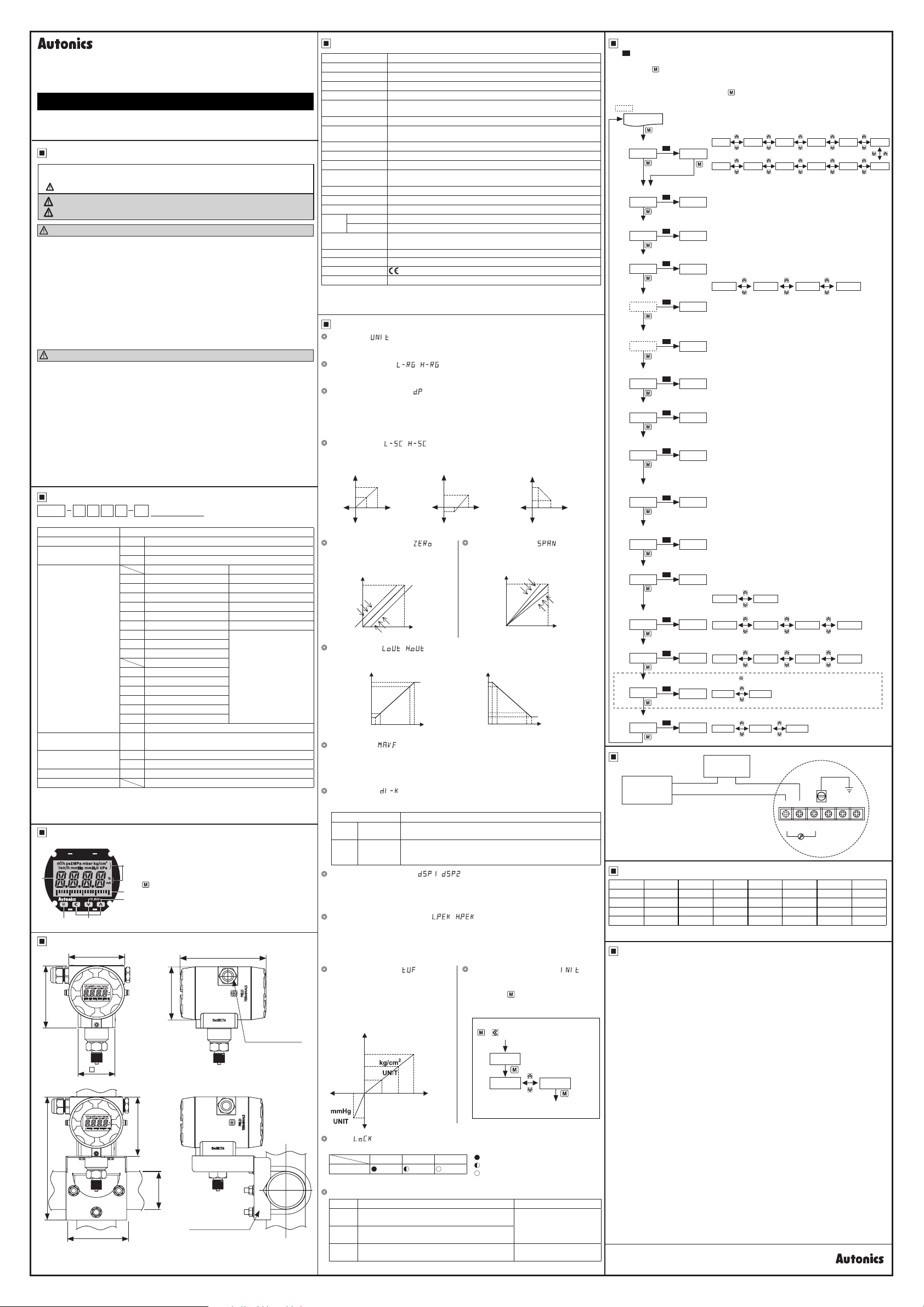
Parameters
00
S
※
1.
: Press any key among the 1, 4, 3 .
-
※
2. 1: Moves digits / 4, 3: Changes SV.
※
3. Press the key after checking/changing SV in each parameter.
The value ashes twice and is saved. t moves to next parameter.
※
4. Defaults are dierent by the pressure range by each model.
※
After entering setting group, press the
in 30 sec, it returns to RUN mode.
※
:This parameter may or may not appear, depending on the other parameter set.
RUN mode
Input unit
UNIT BAR
Low-limit input value
※
4
L RG
High-limit input value
※
4
H RG
Decimal point position
※
4
dP
Low-limit scale value
:···········~
L SC 00)0
'····i[MJ
High-limit scale value
:···········~
H SC 10)0
'····ir0··'
Zero-point correction
ZERO 000
~
Slope correction
SPAN !000
~
Low-limit output
scale value
※
4
lOUT
High-limit output
scale value
※
4
hOUT
Moving average
digital lters
MAvF 04
Digital input
DI K HOLD
Display 1 selection
2
].
DSP1 PV
Display 2 selection
DSP2 PV
Two Unit Function
TUF
Lock
LOCK OFF
Connections
00
~I
------,1_1
INDICATOR
RECORDER
CONTROLLER
.
~-~
※
You can check DC4-20 mA output by connecting
an ampere meter. (impedance: max. 30Ω)
I-----\-\,~-------~//
※
1
S
S
S
S
S
.'
S
S
S
S
S
S
S
S
S
S
S
f-.
※
2
OFF
----------i1--i1
(Ml
key for 3 sec or there is no additional key operation
BAR PA
mBAR KPA MPA gCM
※
3
• Setting range: within the pressure range of input type
• Setting range: within the pressure range of input type
Select the decimal point position of display scale value.
※
Setting range is dierent by the pressure range.
)0 )000)00 0
• Setting range: -1999 to 9999
※
Displayed only when selecting input unit [
% [
] or OFF [
? O
• Setting range: -1999 to 9999
※
Displayed only when selecting input unit [
% [
] or OFF [
? O
Corrects occurring error at 0% input.
• Setting range: -999 to 999
Corrects occurring error at 100% input.
• Setting range: 0.900 to 1.100
• Setting range:
Within temperature range when input unit is standard
pressure unit.
Within display scale range when input unit is % or OFF.
• Setting range:
Within temperature range when input unit is standard
pressure unit.
Within display scale range when input unit is % or OFF.
Set the number of moving average digital lters.
• Setting range: 01 to 16
Select digital input function by front keys.
※
Press the 4, 3 keys for 3 sec at the same time and it
executes the selected function.
Displayed only for compound pressure model.
SOURCE
15-35VDC
+
-
I
'-----I
I
].
OFF
].
OFF
TMHOLD
OUTPV hPEKlPEK
OUTPV hPEKlPEK
ONOFF
LOc1OFF LOc2
~/
/,,,---1
+
-
~H\
~
\11@ll@ll@ll@li@ll@11!
1 2 3 4 5 6
-
+
Ampere
meter
mmH2PSImmHG? OOFF
UNIT
UNIT
~
F.G.
KgCM
] as
] as
\
Factory Default
Parameter Default Parameter Default Parameter Default Parameter Default
UNIT BAR L SC 00)0 lOUT )000 DSP1 PV
L RG )000
H RG )350
dP )350
※
1: Defaults are dierent by the pressure range by each model.
.
]or
r1
1
!:
]
Cautions during Use
00
Follow instructions in 'Cautions during Use'. Otherwise, It may cause unexpected accidents.
1.
15-35VDC power supply should be insulated and limited voltage/current or Class 2, SELV
2.
power supply device.
The connection of this unit should be separated from the power line and high voltage line in
3.
order to prevent inductive noise.
Do not use this unit near the high frequency instruments
4.
Switch or circuit breaker for suppling or cutting o the power should be installed nearby
5.
users for convenient control.
Use veried explosion-proof cable gland or sealing tting.
6.
(explosion proof standard: over Ex d IIC T6, P rating: over IP67 protection structure).
Use dedicated external terminal for earth. For connecting earth, use a spring washer and
7.
earth cable which is over 4mm².
This unit may be used in the following environments.
8.
① Indoor / Outdoor (in the environment condition rated in 'Specications')
② Altitude max. 2,000 m
③Pollution Degree 2
④Installation Category II
※The explosion-proof unit is certied and the same specications which is reported
to Korea Gas Safety Corporation. (This unit is manufactured following by the
announcement 2013-54 of Ministry of Employment and Labor of Korea.)
I
※1
H SC 10)0 hOUT )350 DSP2 PV
※1
ERO 000 MAvF 04※1TUF OFF
※1
SPAN !000 DI K HOLD※1LOCK OFF
Autonics
 Loading...