

Autonics PSQ Series Catalog Page
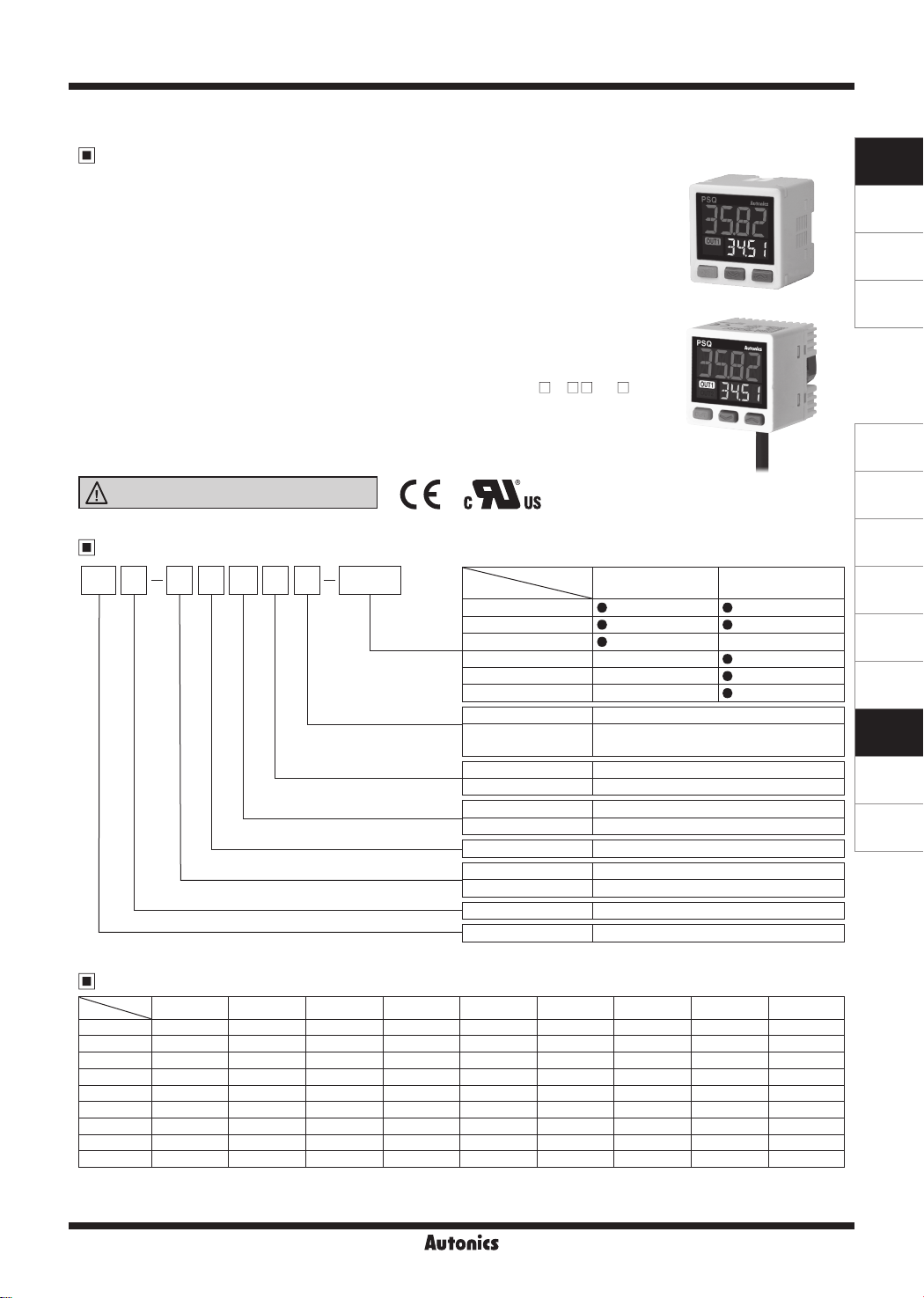
Compact, Dual LCD Display Digital Pressure Sensor
Features
● Pressure measurement of any gas, liquid or oil [Fluid type]
(※except substances which may corrode stainless steel 316L)
● Simultaneous display of present value (PV) and set value (SV)
※Selectable SV, pressure unit, or none display for SV display part
● Selectable NPN, PNP open collector output by parameter setting
● 3 colors for PV display part (run mode: red or green / setting mode: orange)
● 12-segment LCD display for easier value reading
● Measurement range: -100.0 to 100.0kPa, -100 to 1,000kPa
(pneumatic type: compound pressure, uid type: sealed gauge pressure)
● Analog output: voltage (1-5VDC), current (DC4-20mA)
● Parameter copy function
● Option input/output: auto shift, remote zero, hold (only for PSQ-
● Forced output control mode for device testing and maintenance
● Min. display unit: 0.1kPa, 1kPa (variable by model)
● One-touch connector type for easy wiring and maintenance
● Password setting for SV
Please read “Safety Considerations”
in the instruction manual before using.
Ordering Information
PS CQ 01 C
Pressure range
Applicable fluid
Applicable fluid
Appearance
Item
Rc1/8
Pressure port
Option Input/Output
Cable
Pressure port
Rc1/8
R1/8
NPT1/8
R1/4
NPT1/4
9/16-18UNF
No mark
U
No mark
C
01
1
C
No mark
B
Q
PS
C U -
Applied uid
)
Pneumatic type Fluid type
-
-
-
NPN or PNP open collector output
NPN or PNP open collector output +
analog output or external input type
Cable type
Connector type
100kPa
1,000kPa
Compound pressure
Pneumatic type (air, non-corrosive gas)
Fluid type (gas, liquid, oil)
Regular square type (30×30mm), dual display
Pressure Sensor
PSQ Series
Pneumatic type
Fluid type
-
SENSORS
CONTROLLERS
MOTION DEVICES
SOFTWARE
(A)
Photoelectric
Sensors
(B)
Fiber Optic
Sensors
(C)
LiDAR
(D)
Door/Area
Sensors
(E)
Vision
Sensors
(F)
Proximity
Sensors
(G)
Pressure
Sensors
(H)
Rotary
Encoders
(I)
Connectors/
Connector Cables/
Sensor Distribution
Boxes/ Sockets
Pressure Conversion Chart
to
from
Pa kPa MPa kgf/cm
1Pa 1 0.001 0.000001 0.000010197 0.007501 0.101972 0.000145038 0.00001 0.0002953
1kPa 1000.000 1 0.001 0.010197 7.500617 101.971626 0.145038 0.01 0.2953
1MPa 1000000 1000 1 10.197162 7500.61683 101971.626 145.038243 10 295.299875
1kgf/cm298066.5 98.0665 0.098067 1 735.55924 10000.0005 14.223393 0.980665 28.959025
1mmHg 133.322368 0.133322 0.000133 0.001359 1 13.595099 0.019337 0.001333 0.039370
1mmH2O 9.80665 0.009807
-
1psi 6894.733 6.89473 0.006895 0.070307 51.714752 703.016716 1 0.068947 2.036014
1bar 100000.0 100.0000 0.100000 1.019716 750.062 10197.1626 14.503824 1 29.529988
1inHg 3386.388 3.386388 0.003386 0.034532 25.40022 345.315507 0.491156 0.033864 1
E.g.) For calculating 760mmHg to kPa : According to above chart, 1mmHg is 0.133322kPa,
therefore 760mmHg will be 760×0.133322kPa=101.32472kPa.
2
mmHg mmH2O psi bar inHg
0.000099 0.073556 1 0.00142 0.000098 0.002896
G-9
PSQ Series
Pressure and Max. Pressure Display Range
Type MPa kPa kgf/cm² bar psi mmHg inHg mmH2O
Compound
pressure
※
( ) is Max. pressure display range.
-100.0 to 100.0
-
(-101.3 to 110.0)
-100 to 1000
-
(-101 to 1100)
-1.020 to 1.020
(-1.033 to 1.122)
-1.020 to 10.20
(-1.030 to 11.22)
-1.000 to 1.000
(-1.013 to 1.100)
-1.000 to 10.00
(-1.01 to 11.00)
※
For using mmH2O unit, multiply display value by 100.
-14.50 to 14.50
(-14.70 to 15.95)
-14.50 to 145.0
(-14.65 to 159.5)
-750 to 750
(-760.0 to 825.1)
-750 to 7500
(-757.6 to 8251)
-29.5 to 29.5
(-29.91 to 32.48)
-29.5 to 295
(-29.83 to 324.8)
-102.0 to 102.0
(-103.3 to112.2)
-102.0 to 1020
(-103.0 to 1122)
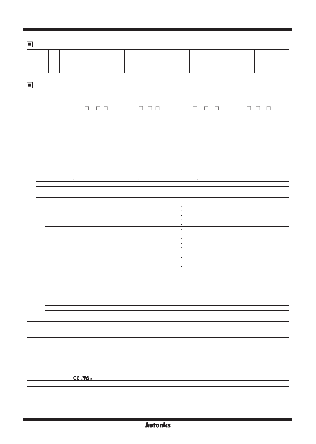
Specifications
※
Pressure type Gauge pressure (In case of uid type, standard
Type NPN or PNP open collector output type
Model
PSQ- C01 - PSQ- C1 - PSQ- C01 U- PSQ- C1 U-
pressure are sealed gauge pressure
NPN or PNP open collector output+
analog output or external input type
Rated pressure range -100.0 to 100.0kPa -100 to 1,000kPa -100.0 to 100.0kPa -100 to 1,000kPa
Display&Setting
pressure range
-101.3 to 110.0kPa -101 to 1,100kPa -101.3 to 110.0kPa -101 to 1,100kPa
Min. display unit 0.1kPa 1kPa 0.1kPa 1kPa
Max.
Pneumatic type
pressure
Fluid type 3 times of rated pressure
range
Applied uid
2 times of rated pressure 1.5 times of rated pressure 2 times of rated pressure 1.5 times of rated pressure
• Pneumatic type:
• Fluid type: air, non-corrosive gas and fluid that do not corrode stainless steel 316L
air, non-corrosive gas
Power supply 12-24VDCᜡ (ripple P-P: max. 10%)
Allowable voltage range 90 to 110% of rated voltage
Current consumption Max. 50mA Max. 50mA (analog output: max. 70mA)
Control output
Hysteresis
NPN or PNP open collector output
Load voltage: max. 30VDCᜡ Load current: max. 100mA Residual voltage: max. 2VDC
※
2
Min. display interval
Repeat error ±0.2% F.S. ± min. display interval
Response time Select one; 2.5ms, 5ms, 10ms, 25ms, 50ms, 100ms, 250ms, 500ms, 1,000ms, 5,000ms
Protection circuit Output short over current protection circuit
Output voltage: 1-5VDCᜡ ±2.5% F.S.
Voltage
output
Analog
※
3
output
Current
output
※
External input
(Auto shift/
Remote zero/Hold)
3
-
-
-
Linear: max. ±1% F.S.
Resolution: 1/2,000
Output impedance: approx. 240Ω
Response time: 50ms
Output current: DC4-20mA ±2.5% F.S.
Linear: max. ±1% F.S.
Resolution: 1/2,000
Output impedance: approx. 100kΩ
Response time: 50ms
ON voltage: max. 0.4VDCᜡ
OFF voltage: 5-Vin or open
Resolution: 1/2,000
Output impedance: approx. 100kΩ
Display digits Present value (PV) display part, setting value (SV) display part: 4-digit
Display method 12-segment LCD method
MPa 0.001 0.001 0.001 0.001
kPa 0.1 1 0.1 1
2
kgf/cm
Min.
bar 0.001 0.01 0.001 0.01
display
psi 0.02 0.2 0.02 0.2
interval
mmHg 1
inHg 0.1
mmH2O 0.1
0.001 0.01 0.001 0.01
-
-
-
1
0.1
0.1
Display accuracy 0 to 50℃: max. ±0.5% F.S., -10 to 0℃: max. ±1% F.S.
Insulation resistance Over 50MΩ (at 500VDC megger)
Dielectric strength 1,000VAC 50/60Hz for 1min
Vibration 1.5mm amplitude at frequency of 10 to 55Hz (for 1min) in each X, Y, Z direction for 2 hours
Environment
Ambient temp.
Ambient humi.
-10 to 50℃, storage: -20 to 60
℃
30 to 80%RH, storage: 30 to 80%RH
Cable (fluid type) Ø4mm, 5-wire, 3m (AWG24, core diameter: 0.08mm, number of cores: 40, insulator out diameter: Ø1mm)
Protection structure
Material
Approval ,
※
4
Weight
※
1: The unit is sealed structure. It is based on atmospheric pressure 101.3kPa.
※
2: In hysteresis output mode, it is variable.
※
3: Select one between analog output (voltage or current) and external input.
※
4: The weight includes packaging. The weight in parenthesis is for unit only.
※
For using mmH2O unit, multiply display value by 100.
※
Environment resistance is rated at no freezing or condensation.
• Pneumatic type:
• Pneumatic type -
• Fluid type -
Front case: polycarbonate, rear case: polyamide 6, pressure port: stainless steel 316L
• Pneumatic type:
IP40 (IEC standard)
Front case: polycarbonate, rear case: polycarbonate, pressure port: brass-nickel plated
approx. 165g (approx. 80g)
• Fluid type:
• Fluid type:
IP65 (IEC standard)
approx. 210g (approx. 125g)
1
)
ᜡ
-
-
-
G-10
Compact, Dual LCD Display Digital Pressure Sensor
Unit Description
3
4 5
Dimensions
Pneumatic type
30
Fluid type
30
30
33.5
1. Present value (PV) display part (green, red, orange by setting/status)
RUN mode: Displays PV.
Setting mode: Displays parameter.
2. Setting value (SV) display part (green)
1
RUN mode: Displays setting value, unit, etc.
Setting mode: Displays SV.
2
3. Output indicator (OUT1, OUT2) (orange): Turns ON while the control output turns ON.
4. M key
RUN mode: Press the M key for over 2 sec to enter parameter 1 group.
Press the M key for over 4 sec to enter parameter 2 group.
Setting mode: Press the M key to select the setting items.
Press the
key
,
5.
M
key for over 2 sec to return RUN mode.
RUN mode: Press the , key to set preset value of output operation mode.
Press the M+ keys to set key lock/unlock.
Press the + keys to adjust zero point.
Press the
M
+ keys to set peak hold.
Preset value setting mode: Press the , key to increase/decrease setting value.
Setting mode: Changes the parameter.
32.7
24.8 7.9
Rc(PT)1/8"
20
2-M3
12
20
32.7
24.8 7.9
※
R1/8 model
NPT1/8 model
30
12.3
A
20
2-M3
※
A
R1/8 model (standard)
Rc1/8 model
R1/4 model
20
Inside
M5 Tap
17
NPT1/4 model
9/16-18UNF model
(metal gasket sealing method)
SENSORS
CONTROLLERS
MOTION DEVICES
SOFTWARE
(A)
Photoelectric
Sensors
(unit: mm)
A
Inside M5 Tab
A
8mm
8mm
0mm
11.5mm
(B)
Fiber Optic
Sensors
(C)
LiDAR
(D)
Door/Area
Sensors
(E)
Vision
Sensors
(F)
Proximity
Sensors
(G)
Pressure
Sensors
(H)
Rotary
Encoders
(I)
Connectors/
Connector Cables/
Sensor Distribution
Boxes/ Sockets
15.4mm
Ø4, 3m
Accessory
Connector cable (PSO-C01, Pneumatic/Fluid type)
※
Ø4mm, 5-wire, 2m
( AWG24, core diameter: 0.08mm,
number of cores: 40,
insulator diameter: Ø1mm)
G-11

PSQ Series
Dimensions
Accessory
Bracket A (Pneumatic type)
Bracket B (Pneumatic type)
4.2
25
35
6
Ø4.2
22
Bracket C (Fluid type)
30
4.2
22
3.5
(unit: mm)
20
4.2
20
30
20
Ø4.2
3-Ø3.2
45
40
30
20
15
1.6
13
Sold separately
Integrated installation set (Pneumatic/Fluid type)
Front cover (PSO-P01)
40
9.7
5.7
1
42
40
Separate installation set (Pneumatic type)
Front cover (PSO-P02)
6.75
7
34.2
Panel bracket (PSO-B02)
40
28.2
30
40
Front/Rear pael bracket set (PSO-B04)
34.4
30.5
3-Ø3.2
20
3
Ø22
45
40
1.6
423526
3
20
25.8
<Rear panel bracket><Front panel bracket>
42
39.8
34.2
20
20
36
4-Ø3.2
40
Panel cut-out
(panel thickness 0.8 to 3.5mm)
16.9
9
55
15
+0.5
36
0
Panel cut-out
0
31
-0.4
( panel thickness: 0.5 to 7mm)
G-12
41
37
<When 'N' units are installed in series>
31×N+3.5×(N-1)
-0.4
0
31
Min. 55
M5 gender (PSO-Z01, Pneumatic type)
34.2
9
 Loading...