

Autonics E80H Series Catalog Page
E80H Series
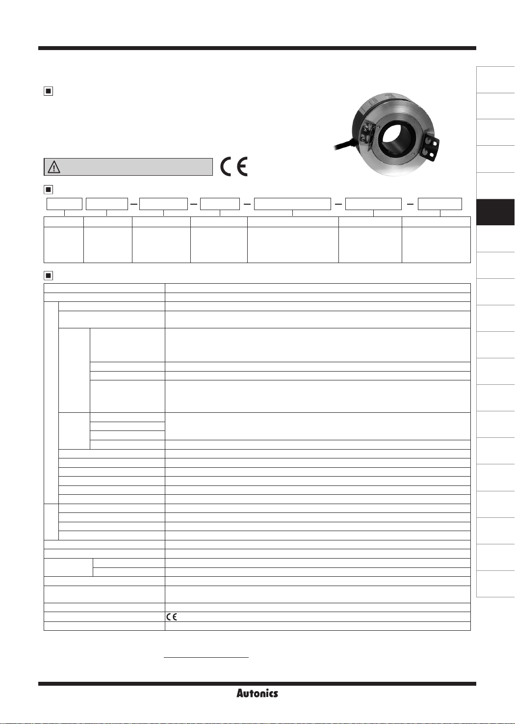
Incremental Ø80mm Hollow Shaft Type
Hollow Shaft Type Ø80mm Incremental Rotary Encoder
Features
● Ø80mm, Inner diameter of shaft Ø30mm, Ø32mm
● No coupling needed with direct installation at motor or rotation
shaft of machine
● Power supply: 5VDC, 12-24VDC ±5%
● Various output types
Please read “Safety Considerations” in operation
manual before using.
.___I
&
____
Ordering Information
E80H 30 3200
I I
I I
Series Shaft diameter Pulses/revolution Output phase Control output Power supply Cable
Ø80mm,
hollow shaft
type
30: Ø30mm
32: Ø32mm
Specifications
Item Hollow Shaft Type Ø80mm Incremental Rotary Encoder
Resolution (PPR)
Output phase A, B, Z phase (line driver output A, A_, B, B_, Z, Z _phase)
Phase difference of output
Totem pole output
Control
output
Response
time
Electrical specication
(rise, fall)
Max. response frequency 200kHz
Power supply • 5VDCᜡ ±5% (ripple P-P: max. 5%) • 12-24VDCᜡ ±5% (ripple P-P: max. 5%)
Current consumption Max. 80mA (disconnec ion of he load), Line driver output: max. 50mA (disconnection of the load)
Insulation resistance Over 100MΩ (at 500VDC megger between all terminals and case)
Dielectric strength 750VAC 50/60Hz for 1 minute (between all terminals and case)
Connection Radial cable type, Radial cable connector type
Starting torque Max. 200gf·cm (0.0196N·m)
Moment of inertia Max. 800g·cm² (8×10
Shaft loading Radial: max. 5kgf, Thrust: max. 2.5kgf
Mechanical
specication
Max. allowable revolution
Vibra ion 1.5mm amplitude at frequency of 10 to 55Hz (for 1 min) in each X, Y, Z direction for 2 hours
Shock Approx. max. 75G
Environment
Protec
Cable
Accessory Spring bracket
Approval
Unit weight
※
Not indicated resolutions are customizable.
1:
※
Make sure that max. response revolution should be lower than or equal to max. allowable revolution when selecting the resolution.
2:
[Max. response revolution (rpm)=
※
Environment resistance is rated at no freezing or condensa ion.
NPN open collector output
Voltage output Load current: max. 10mA, residual voltage: max. 0.4VDC
Line driver output
Totem pole output
NPN open collector output
Voltage output
Line driver output Max. 0.5
Ambient temperature -10 to 70℃, storage: -25 to 85
I
Ambient humidity 35 to 85%RH, storage: 35 to 90%RH
I
ion structure IP50 (IEC standard)
1-1
I
60, 100, 360,
500, 512, 1024,
3200
※
1
※
2
Max. response frequency
Resolution
___.I C €
1-1
3 N
1-1 1-1
I
I
T: Totem pole output
3: A, B, Z
6: A, A_, B, B_, Z, Z
N: NPN open collector output
_
V: Voltage output
L: Line driver output
60, 100, 360, 500, 512, 1024, 3200
T ± T
_
Output between A and B phase:
4_ 8
(T=1 cycle of A phase)
• [Low] - Load current: max. 30mA, residual voltage: max. 0.4VDC
• [High] - Load current: max. 10mA,
Output voltage (power voltage 5VDCᜡ): min. (power voltage-2.0)VDCᜡ,
Output voltage (power voltage 12-24VDCᜡ): min. (power voltage-3.0)VDC
Load current: max. 30mA, residual voltage: max. 0.4VDC
• [Low] - Load current: max. 20mA, residual voltage: max. 0.5VDC
• [High] - Load current: max. -20mA,
Output voltage (power voltage 5VDCᜡ): min. 2.5VDCᜡ,
Output voltage (power voltage 12-24VDCᜡ): min. (power voltage-3.0)VDC
Max. 1
cable length: 2m, I sink = 20mA)
㎲ (
cable length: 2m, I sink = 20mA)
㎲ (
-5
kg·m²)
3,600rpm
℃
Ø5mm, 5-wire (line driver output: 8-wire), 2m, Shield cable
(AWG24, core diameter: 0.08mm, number of cores: 40, insulator out diameter: Ø1mm)
(except for line driver output)
CE
Approx. 560g
× 60 sec]
24
I I
5: 5VDC ±5%
24: 12-24VDC ±5%
ᜡ
ᜡ
ᜡ
ᜡ
-I
No mark: Radial
C: Radial cable
connector type
ᜡ
ᜡ
cable type
I
(A)
Photoelectric
Sensors
(B)
Fiber
Optic
Sensors
(C)
Door/Area
Sensors
(D)
Proximity
Sensors
(E)
Pressure
Sensors
(F)
Rotary
Encoders
(G)
Connectors/
Connector Cables/
Sensor Distribution
Boxes/Sockets
(H)
Temperature
Controllers
(I)
SSRs / Power
Controllers
(J)
Counters
(K)
Timers
(L)
Panel
Meters
(M)
Tacho /
Speed / Pulse
Meters
(N)
Display
Units
(O)
Sensor
Controllers
(P)
Switching
Mode Power
Supplies
(Q)
Stepper Motors
& Drivers
& Controllers
(R)
Graphic/
Logic
Panels
(S)
Field
Network
Devices
(T)
Software
Autonics
F-33
E80H Series
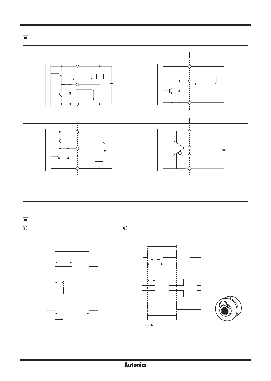
Control Output Diagram
Totem pole output NPN open collector output
Rotary encoder circuit
Load Connection
Rotary encoder circuit
Load Connection
+V
※
Sink current
: max. 30mA
Output
R
'
Source current
: max. 10mA
7
0V
Load Connection
+V
Source current
: max. 10mA
Output
0V
Main circuit
Voltage output Line driver output
Rotary encoder circuit
~--0----
Main circuit
● All output circuits of A, B, Z phase are same. (line driver output is A, A_, B, B_, Z, Z_)
● Totem pole output type can be used for NPN open collector type (※1) or voltage output type (※2).
Load
Load
Load
1
※
2
1
+
-
Main circuit
Rotary encoder circuit
+
-
Main circuit
+V
Output
Sink current
: max. 30mA
0V
Load Connection
+V
A phase
output
_
phase
A
output
0V
Load
+
-
+
-
Output Waveforms
Totem pole output /
NPN open collector output /
Voltage output
T
T ± T
2 4
H
phase
A
phase
B
phase
Z
L
H
L
H
L
T ± T
~
4 8
' '
~
! i I \
' '
' '
' '
~
T ±
Clockwise (CW)
T
_
2
-
F-34
Line driver output
T
'
H
phase
A
_
phase
A
:
phase
B
_
phase
B
phase
Z
_
phase
Z
T ± T
L
~
' - '
2 4
H
L
~
: '
T ± T
- -
'
4 8
' '
H
L
H
L
H
L
H
L
T ±
Clockwise (CW)
'
CW
T
_
2
-
Autonics
 Loading...