

Autonics E58 Series Catalog Page
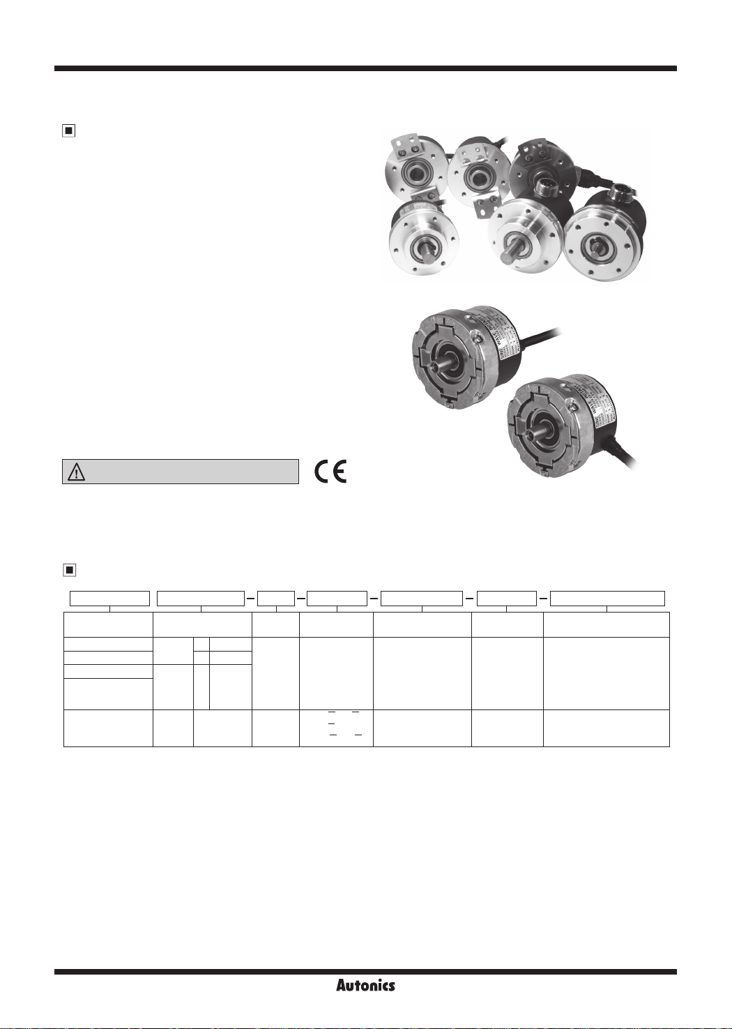
E58 Series
Ø58mm Incremental Rotary Encoder
Features
[ Totem pole, NPN open collector, Voltage,
Line driver output type]
● Ø58mm ange type
● Suitable for measuring angle, position, revolution, speed,
acceleration and distance
● Power supply: 5VDC, 12-24VDC ±5%
[Analog sine wave OP Amp output type]
● Taper shaft
● Analog sine wave OP Amp output
● Power supply: 5VDC ±5%
Please read “Safety Considerations” in operation
manual before using.
'-=l&
_____
I C €
Ordering Information
E58SC
I
Series (Ø58mm) Shaft diameter
SC: Shaft Clamping
SS: Shaft Synchro 6 Ø6mm
H: Hollow shaft
HB: Blind hollow
shaft
S: Shaft External Ø9.25mm 2048
1: Please refer to 'connection' in the specifications for the detailed information about cable.
※
11
10
10 Ø10mm
External
Inner 12 Ø12mm
l-~-1
Pulses/
revolution
Refer to
resolution
3 N 248000
1-1
Output phase Control output Power supply Cable
2: A, B
3: A, B, Z
4: A, A_, B, B
6: A, A_, B, B_,
_
Z, Z
10: A, A, B, B,
-
Z, Z,
- -
C, C, D, D
T: Totem pole output
N: NPN open
_
collector output
V: Voltage output
L: Line driver output
A: Analog sine wave
OP Amp output
1-1
5: 5VDC ±5%
24: 12-24VDC
±5%
5: 5VDC ±5%
1-1
1
※
No mark
: Axial/Radial cable type
C: Axial/Radial cable
connector type
CR: Axial connector type
CS: Radial connector type
R: Axial cable type
S: Radial cable type
I
G-24
Autonics
Incremental Ø58mm Shaft/Hollow Shaft/Blind Hollow Shaft Type
Shaft Type/Hollow Shaft Type/Blind Hollow Shaft Type Ø58mm
Incremental Rotary Encoder
SENSORS
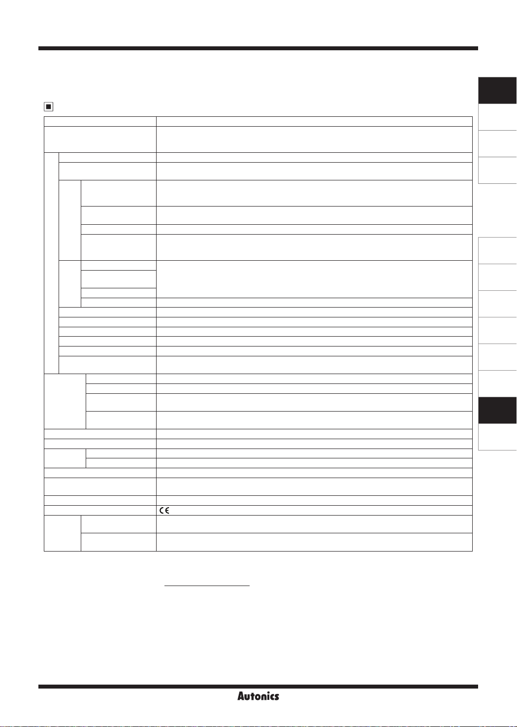
Specifications
Item Shaft Type/Hollow Shaft Type/Blind Hollow Shaft Type Ø58mm Incremental Rotary Encoder
※
Resolution (PPR)
1
Output phase A, B, Z phase (line driver output: A, A, B, B, Z, Z phase)
Phase dierence of output
Totem pole output
NPN open collector
output
Voltage output Load current: max. 10mA, residual voltage: max. 0.4VDC
Control output
Line driver output
Totem pole output
NPN open collector
output
Voltage output
Electrical specication
(rise, fall)
Line driver output Max. 0.5
Response ime
Max. response frequency 300kHz
Power supply • 5VDC
Current consumption Max. 80mA (disconnection of the load), Line driver output: max. 50mA (disconnection of the load)
Insulation resistance Over 100MΩ (at 500VDC megger between all terminals and case)
Dielectric strength 750VAC 50/60Hz for 1 min (between all terminals and case)
Connection
Star ing torque • SC/SS type: max. 40gf·cm (0.004N·m) • H/HB type: max. 90gf·cm (0.009N·m)
Moment of inertia • SC/SS type: max. 15g·cm2 (1 5×10
Mechanical
specication
Shaft loading
Max. allowable
revolution
※
2
Vibra ion 1.5mm amplitude at frequency of 10 to 55Hz (for 1 min) in each X, Y, Z direction for 2 hours
Shock Approx. max. 75G
Environment
Protec
Ambient temperature -10 to 70℃, storage: -25 to 85
Ambient humidity 35 to 85%RH, storage: 35 to 90%RH
ion structure IP50 (IEC standard)
Cable
Accessory Coupling (SC type: Ø10mm, SS type: Ø6mm), Bracket
Approval
Cable type,
Cable connector type
※
3
Weight
Connector type
※
'*' pulse is only for A, B phase. (line driver output is for A, A_, B, B_ phase) [In case of hollow shaft type, 6000, 8000 PPR excluded] Not
1:
indicated resolutions are customizable.
※
Make sure that max. response revolution should be lower than or equal to max. allowable revolution when selecting the resolution.
2:
[Max. response revolution (rpm)=
※
3: The weight includes packaging. The weight in parenthesis is for unit only.
※
Environment resistance is rated at no freezing or condensa ion.
1, *2, *5, 10, *12, 15, 20, 23, 25, 30, 35, 40, 45, 50, 60, 75, 100, 120, 125, 150, 192, 200, 240, 250,
*
256, 300, 360, 400, 500, 512, 600, 800, 1000, 1024, 1200, 1500, 1800, 2000, 2048, 2500, 3000, 3600,
5000, 6000, 8000
T ± T
_
Output between A and B phase:
4
• [Low] - Load current: max. 30mA, residual voltage: max. 0.4VDC
• [High] - Load current: max. 10mA, output voltage (power voltage 5VDC
output voltage (power voltage 12-24VDCᜡ): min. (power voltage-3.0)VDC
Load current: max. 30mA, residual voltage: max. 0.4VDC
_
(T=1 cycle of A phase)
8
ᜡ
): min. (power voltage-2.0)VDCᜡ,
ᜡ
ᜡ
ᜡ
ᜡ
• [Low] - Load current: max. 20mA, residual voltage: max. 0.5VDC
• [High] - Load current: max. -20mA, output voltage (power voltage 5VDC
ᜡ
): min. 2.5VDCᜡ,
ᜡ
output voltage (power voltage 12-24VDCᜡ): min. (power voltage-3.0)VDC
Max. 1
cable length: 2m, I sink = 20mA)
㎲ (
cable length: 2m, I sink = 20mA)
㎲ (
±5% (ripple P-P: max. 5%) • 12-24VDC
ᜡ
±5% (ripple P-P: max. 5%)
ᜡ
• SC/SS/HB type: axial cable type, axial cable connector type, axial/radial connector type
• H type: radial cable type, radial cable connector type
-6
2
) • H/HB type: max. 20g·cm2 (2×10
kg·m
-6
kg·m
• SC/SS type-Radial: max. 10kgf, Thrust: max. 2 5kgf
• H/HB type-Radial: max. 2kgf, Thrust: max. 1kgf
5,000rpm
℃
Ø5mm, 5-wire (line driver output: 8-wire), 2m, Shield cable
(AWG24, core diameter: 0.08mm, number of cores: 40, insulator out diameter: Ø1mm)
(except for line driver output)
CE
• SC type: approx. 420g (approx. 310g) • SS type: approx. 395g (approx. 285g)
• H/HB type: approx. 380g (approx. 270g)
• SC type: approx. 340g (approx. 230g) • SS type: approx. 315g (approx. 205g)
• HB type: approx. 310g (approx. 200g)
Max. response frequency
Resolution
× 60 sec]
CONTROLLERS
MOTION DEVICES
OTHERS
(A)
Photoelectric
Sensors
ᜡ
(B)
Fiber Optic
Sensors
(C)
Door/Area
Sensors
(D)
Vision
Sensors
(E)
Proximity
Sensors
(F)
2
)
Pressure
Sensors
(G)
Rotary
Encoders
(H)
Connectors/
Connector Cables/
Sensor Distribution
Boxes/ Sockets
Autonics
G-25

E58 Series
Control Output Diagram
Totem pole output NPN open collector output Voltage output Line driver output
Rotary encoder circuit
Main circuit
● All output circuits of A, B, Z phase are same. (line driver output is A, A_, B, B_, Z, Z_)
● Totem pole output type can be used for NPN open collector type (※1) or voltage output type (※2).
Output Waveforms
Totem pole output /
NPN open collector output /
Voltage output
A phase
B phase
Z phase
Load connection
+V
Sink current
: max. 30mA
Output
Source current
: max. 10mA
0V
T ± T
_
2
H
L
H
L
H
L
T ± T
'
4_ 8
'
~
'
'
~
'
-
※
1
Load
+
-
※
2
Load
T
_
4
_
,----
T
_
T ±
2
Clockwise (CW)
Rotary encoder circuit
Main circuit
I
'
Load connection
+V
Load
Output
Sink current
: max. 30mA
0V
Rotary encoder circuit
+
-
Main circuit
Line driver output
H
A phase
L
_
H
phase
A
L
H
B phase
L
_
H
B
phase
Z phase
_
Z
phase
---+---,
L
H
L
H
L
-
R
T
T ± T
_
_
4
2
T ± T
_
_
8
4
:
L___J
T ±
2
Clockwise (CW)
Load connection
+V
Source current
: max. 10mA
Output
Load
0V 0V
r-:---7
T
_
Rotary encoder circuit
+ +
-
Main circuit
L___J
r
:
Load connection
+V
A phase
output
A_ phase
output
CW
-
Connections
Axial/Radial cable type
● Totem pole output /
NPN open collector output /
Voltage output
● Line driver output
※
Unused wires must be insulated.
※
The metal cable and shield cable of encoder should be
grounded (F.G.)
※
Do not apply tensile streng h over 30N to the cable.
G-26
Black: OUT A
White: OUT B
Orange: OUT Z
Brown: +V (5VDC, 12-24VDC ±5%)
Blue: GND (0V)
Shield: F.G.
Black: OUT A
Red: OUT A
White: OUT B
Gray: OUT B
Orange: OUT Z
Yellow: OUT Z
Brown: +V (5VDC, 12-24VDC ±5%)
Blue: GND (0V)
Shield: F.G.
_
_
_
Axial/Radial cable connector type /
Axial/Radial connector type
● Totem pole output /
NPN open collector output /
Voltage output
2
1
3 6
4
5
Pin No. Function Cable color
OUT A Black
1
OUT B White
2
OUT Z Orange
3
+V Brown
4
GND Blue
5
F.G. Shield
6
※
F.G. (field ground): It should be grounded separately.
Autonics
● Line driver output
1
2
3
4 5 6
7 8 9
Pin No. Function Cable color
OUT A Black
1
OUT A Red
2
+V Brown
3
GND Blue
4
OUT
5
6
7
8
9
B White
_
OUT B
OUT Z Orange
OUT Z Yellow
F
Gray
.G. Shield
 Loading...