

Autonics E50S SERIES Instruction Manual
DRW171369AA
Autonics
ROTARY ENCODER (INCREMENTAL TYPE)
E50S SERIES
I N S T R U C T I O N M A N U A L
Please read the following safety considerations before use.
Safety Considerations
Please observe all safety considerations for safe and proper product operation to avoid
※
hazards.
symbol represents caution due to special circumstances in which hazards may occur.
※
Warning
Caution
Warning
1. Fail-safe device must be installed when using the unit with machinery that may cause
serious injury or substantial economic loss. (e.g. nuclear power control, medical equipment,
ships, vehicles, railways, aircraft, combustion apparatus, safety equipment, crime/disaster
prevention devices, etc.)
Failure to follow this instruction may result in re, personal injury, or economic loss.
2. Install on a device panel to use.
Failure to follow this instruction may result in re.
3. Do not connect, repair, or inspect the unit while connected to a power source.
Failure to follow this instruction may result in re.
4. Check 'Connections' before wiring.
Failure to follow this instruction may result in re.
5. Do not disassemble or modify the unit.
Failure to follow this instruction may result in re.
Caution
1. Use the unit within the rated specications.
Failure to follow this instruction may result in re or product damage.
2. Do not short the load.
Failure to follow this instruction may result in product damage by re.
3. Do not use the unit in the place where ammable/explosive/corrosive gas, humidity,
direct sunlight, radiant heat, vibration, impact, or salinity may be present.
Failure to follow this instruction may result in re or explosion.
4. Do not use the unit near the place where there is the equipment which generates strong
t-=-----------y~i---------;------------_J
magnetic force or high frequency noise and strong alkaline, strong acidic exists.
Failure to follow this instruction may result in product damage.
I~
Ordering Information
E50S 8 - 8000 - 3 - N - 24 -
Shaft
Series
diameter
Diameter
Ø50mm,
Ø8mm
shaft
type
※
Standard: E50S8-
Control Output Diagram
Totem pole output NPN open collector output
Rotary encoder circuit Load connection Rotary encoder circuit Load connection
Voltage output Line driver output
Rotary encoder circuit Load connection Rotary encoder circuit Load connection
※
All output circuits of A, B, Z phase are the same. (line driver output is A, A, B, B, Z, Z)
※
Totem pole output type can be used for NPN open collector type (
※
The above specications are subject to change and some models may be discontinued
without notice.
※
Be sure to follow cautions written in the instruction manual, and the technical descriptions
(catalog, homepage).
Thank you for choosing our Autonics product.
Failure to follow these instructions may result in serious injury or death.
Failure to follow these instructions may result in personal injury or product damage.
Pulse/
1Revolution
Main circuit
Main circuit
Output phase Control output Power supply Cable
Refer to
resolution
PULSE
Sink current:
Max. 30mA
Source
current:
Max. 10mA
2: A, B
3: A, B, Z
4: A, A, B, B
6: A, A, B, B,
Z, Z
-3-N-24
+V
Output
0V
+V
Source
current:
Max. 10mA
Output
0V
Load
T: Totem pole output
N: NPN open collector
output
V: Voltage output
L: Line driver output
※
1
Load
+
-
※
2
Load
+
-
No mark:
Axial cable type
5: 5VDC±5%
24: 12-24VDC
±5%
Main circuit
Main circuit
※
1) or voltage output type (
C: Axial cable
CR:
CS: Radial connector
+V
0V
+V
A phase
output
A
output
0V
connector type (
Axial connector type
type
※
Cable length: 250mm
Output
Sink
current:
Max. 30mA
phase
Load
※)
+
-
+
-
※
2).
Specications
Item Diameter Ø50mm shaft type of incremental rotary encoder
Totem pole output E50S8-
NPN open collector output E50S8-
Voltage output E50S8-
Model
Line driver output E50S8-
1
Resolution (PPR)
Electrical
Mechanical
Vibration 1.5mm amplitude at frequency of 10 to 55Hz in each X, Y, Z direction for 2 hours
Shock Approx. Max. 75G
Environment
Protection structure Axial cable type, Axial cable connector type: P50 (IEC standards)
Cable
Accessory Ø8mm coupling, Bracket
Approval
Weight
※
1 '*' pulse is only for A, B phase. (but Line driver output: A, A, B, B phase) Not indicated resolutions are customizable.
※
2 This value is for Axial cable type, Axial cable connector type (protection structure: P50).
※
3 This value is for Axial cable type, Axial cable connector type (protection structure: P64), Axial/Radial connector type (protection structure: P65).
※
4 Make sure that Max. response revolution should be lower than or equal to max. allowable revolution when selecting the resolution.
【
※
5 In case of axial cable type, a
※
6 The weight includes packaging. The weight in parentheses is for unit only.
※
Environment resistance is rated at no freezing or condensation.
※
Output phase A, B, Z phase (line driver output: A, A, B, B, Z, Z phase)
Phase difference of output Output between A and B phase:
Totem pole output
Control
NPN open collector output Load current: Max. 30mA, Residual voltage: Max. 0.4VDC
output
Voltage output Load current: Max. 10mA, Residual voltage: Max. 0.4VDC
Line driver output
Totem pole output
Response
time
specication
specication
※
Max. response revolution (rpm)=
Voltage output
(rise/fall)
Line driver output Max. 0 5㎲ (cable length: 2m, I sink=20mA)
Max. Response frequency 300kHz
Power supply
Current consumption Max. 80mA (disconnection of the load), Line driver output: Max. 50mA (disconnection of the load)
Insulation resistance Over. 100MΩ (at 500VDC megger between all terminals and case)
Dielectric strength 750VAC 50/60Hz for 1 minute (between all terminals and case)
Connection Axial cable type, Axial cable connector type, Axial/Radial connector type
Starting torque Max. 70gf.cm (0 007N.m)
Moment of inertia Max. 80g cm2 (8×10⁻⁶kg m2)
Shaft loading Radial: Max. 10kgf, Thrust: Max. 2 5kgf
Max. allowable revolution
Ambient temperature -10 to 70℃, Storage: -25 to 85
I
Ambient humidity 35 to 85% RH, Storage: 35 to 90%RH
I
6
Resolution
Dimensions
Axial cable type, Axial cable connector type (IP50)
◎
3-M3×0 5 DP: 8
P.C.D 40
3-120°
Axial cable type, Axial cable connector type (IP64)
◎
3-M3×0 5 DP: 8
P.C.D 40
3-120°
Cable for Axial cable type Cable for Axial cable connector type
Ø5, 5-wire (line driver output: 8-wire),
Length: 2000mm, Shield cable
Axial connector type
◎
3-M3×0 5 DP: 8
P.C.D 40
3-120°
Radial connector type
◎
3-M3×0 5 DP: 8
P.C.D 40
3-120°
-3-T- -
CJ
□□
-3-N- -
CJ
□□
-3-V- -
CJ
□□
-6-L- -
CJ
*1, *2, *5, 10, 12, 15, 20, 23, 25, 30, 35, 40, 45, 50, 60, 75, 100, 120, 125, 150, 192, 200, 240, 250, 256, 300, 360, 400, 500, 512, 600, 800, 1000, 1024, 1200, 1500, 1800, 2000,
2048, 2500, 3000, 3600, 4000, 5000, 6000, 8000
● [Low] - Load current: Max. 30mA, Residual voltage: MAax. 0.4VDC
● [High] - Load current
: Max. 10mA, Output voltage (power voltage 5VDCᜡ): Min. (power voltage-2.0)VDCᜡ, Output voltage (power voltage 12-24VDCᜡ): Min. (power voltage-3 0)VDC
●
[Low] - Load current: Max. 20mA, Residual voltage: Max. 0 5VDC
●
[High] - Load current: Max. -20mA, Output voltage (power voltage 5VDCᜡ): Min. 2.5VDCᜡ, Output voltage (power voltage 12-24VDCᜡ): Min. (power voltage-3.0)VDC
Max. 1㎲ (cable length: 2m, I sink=20mA)NPN open collector output
●
5VDCᜡ ±5% (ripple P-P: Max. 5%)● 12-24VDCᜡ ±5% (ripple P-P: Max. 5%)
4
※
xial cable connector type
5,000rpm
Ø5mm, 5-wire, Length: 2m, Shield cable (line driver output: Ø5mm, 8-wire)
(AWG 24, Core diameter: 0 08mm, Number of cores: 40, Insulator diameter: Ø1mm)
(except line driver output)
CE
Approx. 363g (approx. 275g), Axial/Radial connector type: Approx. 268g (approx. 180g)
Max. response frequency
-00
-002
Ø50
Ø30
] 1
-00
-002
0007
00 7
Ø28
Ø50
J11M-O~~~
Ø50
Ø50
Ø8
Ø30
00
002
-0007
-00 7
Ø28
Ø8
Ø30
-00
-002
0007
00 7
Ø28
Ø8
Ø30
□□
T
T
±
(T=1cycle of A phase)
4
8
ᜡ
ᜡ
2
※
, Max. 800gf cm (0 078N.m)
2
※
, Max. 400g.cm2 (4×10⁻⁵kg.m2)
℃
× 60 sec
】
, they are available to order the option protection structure IP64.
15 8
5 37.5 20
-0007
-00 7
Ø8
®~-~
15.8
10
15 8 43 9.47 5 5
10
15.8 57 5 43
10
}L
37.5 207 5 5
Ø5, 5-wire (line driver output: 8-wire),
Length: 250mm, Shield cable
13.5
9.4
22
3
※
(unit: mm)
3
※
ᜡ
ᜡ
5
※
, Axial/Radial connector type: P65 (IEC standards)
Bracket
◎
45
1520
~
55
65
ITB
View (A)
Coupling
◎
Ø19
3.4
+0
0
Ø8
@-imt_
※
Do not put strong impact when insert a coupling into shaft.
Failure to follow this instruction may result in product damage.
※
Fix the unit or a coupling by a wrench under 0.15 N m of torque.
※
When you install this unit, if eccentricity and deection angle are larger, it may shorten the life cycle of this unit.
Connector cable (sold separately)
◎
●CID6S-2, CID6S-5, CID6S-10, CID6S-15
(Totem pole output/NPN open collector output/Voltage output)
6
1
5
234
Ø19
●CID9S-2, CID9S-5, CID9S-10, CID9S-15
(Line driver output)
r--------~
6
2
5
9
48
1
Ø19
37
43
43
25
A
A
~ci
41
View (A)
J
3.4
4-M4×0.7
Parallel misalignment: Max. 0.25mm
Angular misalignment: Max. 5°
End-play: Max. 0.5mm
※
Ø5
Model Control output Cable length (A)
~=;====~==:]
CID6S-2
CID6S-5 5m
CID6S-10 10m
CID6S-15 15m
Ø5
CID9S-2
11--+--_____j
CID9S-5 5m
CID9S-10 10m
CID9S-15 15m
65
Uf!l_
Do not load overweight on the shaft.
Totem pole output
NPN open collector output
Voltage output
Line driver output
60
1·
35
'I
2m
f------------"
c----------J•
2m
f------------"
c----------J
ᜡ
(unit: mm)
Ø30
Connections
Axial cable type
◎
● Totem pole output
● NPN open collector output
● Voltage output
Black: OUT A
White: OUT B
Orange: OUT Z
Brown:
+V (5VDC, 12-24VDC ±5%)
Of
●
Line driver output
ᜡ
~
※
nused wires must be insulated.
U
The metal case and shield cable of encoder should
※
be grounded (F.G.).
Do not apply tensile strength over 30N to the
※
cable.
Blue: GND (0V)
Shield: F.G.
Black: OUT A
-
Red: OUT A
White: OUT B
-
Gray: OUT B
Orange: OUT Z
Yellow: OUT Z
Brown:
Blue: GND (0V)
Shield: F.G.
-
+V (5VDC, 12-24VDC ±5%)
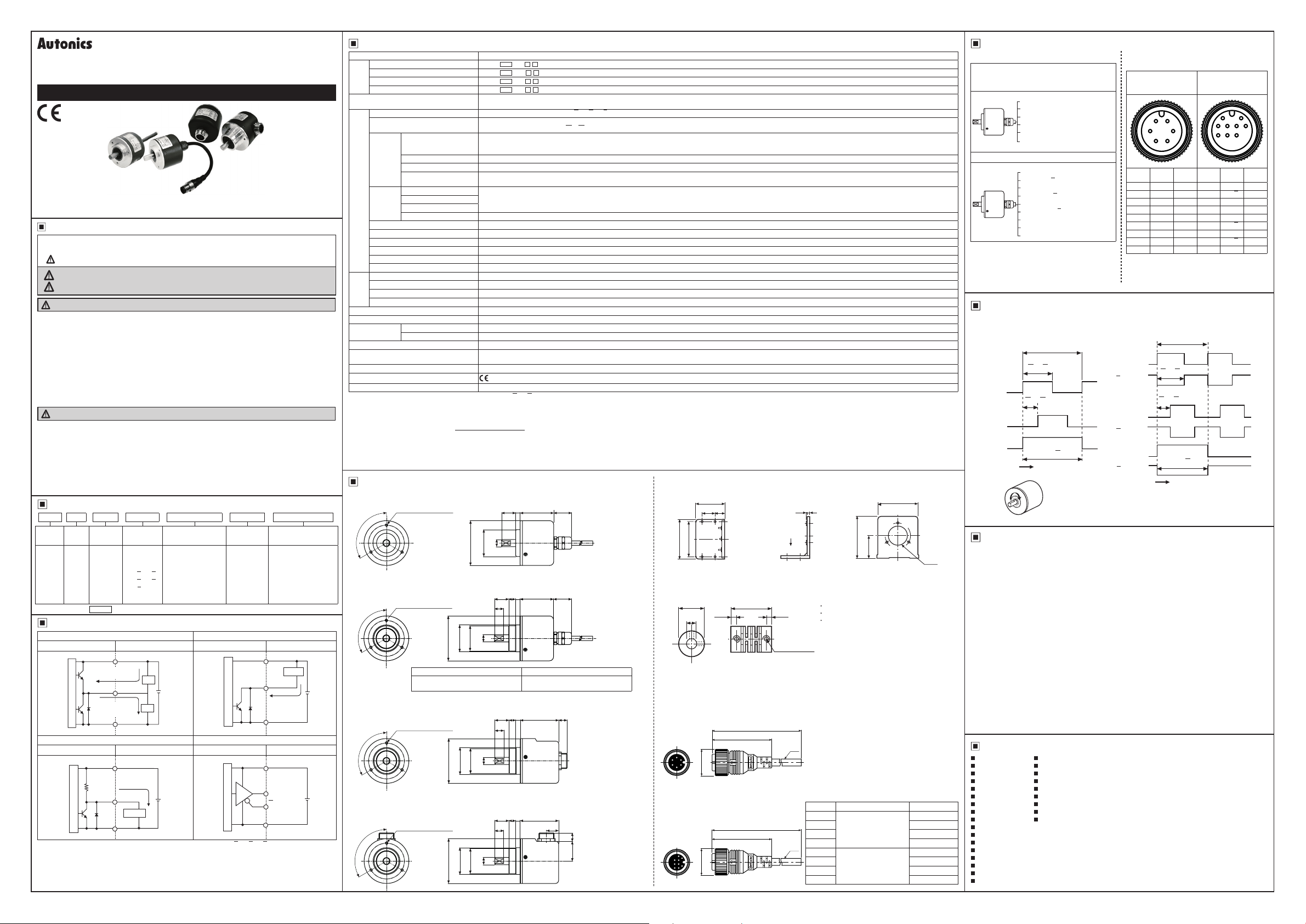
Axial cable connector type/
◎
Axial/Radial connector type
● Totem pole output
●
NPN open collector output
● Voltage output
3
4 5
Pin No.
Function
1
OUT A
2
OUT B
3
OUT Z
4
+V
5
GND
6
F.G.
F.G. (Field Ground): It should be grounded
※
separately.
12
6
Cable
color
Black 1
White 2
Orange 3
Brown 4
Blue 5
Shield 6
●
Line driver output
1 2
3748596
Function
Pin No.
OUT A
OUT
+V
GND
OUT B
OUT
7
OUT Z
8
OUT
9
F.G.
Cable
color
Black
A Red
Brown
Blue
White
B Gray
Orange
Z Yellow
Shield
Output Waveforms
:
● Line driver output
'
H
A phase
L
T2T
~
H
A phase
-
~
L
T4T
' '
I-
H
B phase
L
--P7---LJ7-
H
-
:7
B phase
Z phase
Z phase
:
L
' '
H
L
H
L
T
±
4
±
- :
8
.-+-, r
L___J
T
±
T
2
Clockwise (CW)
;
L_J
● Totem pole output/
NPN open collector output/
Voltage output
T2T
±
hi
H
A phase
_____f7________
L
T4T
±
1-
- I
~
H
B phase
Z phase
_J_J--i__J_
L
'
H
L
---r--=-i---
Clockwise (CW)
-
CW
T
4
8
T
±
T
2
Cautions during Use
1. Follow instruc ions in 'Cautions during Use'. Otherwise, It may cause unexpected
accidents.
2. 5VDC, 12-24VDC power supply should be insulated and limited voltage/current
or Class 2, SELV power supply device.
3. For using the unit with the equipment which generates noise (switching regulator,
inverter, servo motor, etc.), ground the shield wire to the F.G. terminal.
4. Ground the shield wire to the F.G. terminal.
5. When using switching mode power supply, frame ground (F.G.) terminal of power supply
should be grounded.
6. Wire as short as possible and keep away from high voltage lines or power lines,
to prevent inductive noise.
7. For Line driver unit, use the twisted pair wire which is attached seal and use the
receiver for RS-422A communication.
8. Check the wire type and response frequency when extending wire because of distortion
of waveform or residual voltage increment etc by line resistance or capacity between
lines.
9. This unit may be used in the following environments.
Indoors (in the environment condition rated in 'Specications')
①
Altitude max. 2,000m
②
Pollution degree 2
③
Installation category II
④
Major Products
~
Photoelectric Sensors Temperature Controllers
■
Fiber Optic Sensors Temperature/Humidity Transducers
■
Door Sensors SSRs/Power Controllers
■
Door Side Sensors Counters
■
Area Sensors Timers
■
Proximity Sensors Panel Meters
Pressure Sensors Tachometer/Pulse (Rate) Meters
Rotary Encoders Display Units
:
Connector/Sockets Sensor Controllers
■
Switching Mode Power Supplies
■
Control Switches/Lamps/Buzzers
I/O Terminal Blocks & Cables
Stepper Motors/Drivers/Motion Controllers
:
Graphic/Logic Panels
Field Network Devices
■
Laser Marking System (Fiber, CO₂, Nd: YAG)
■
Laser Welding/Cutting System
■
■
■
■
■
■
■
■
■
■
DRW171369 AA
 Loading...