

DRW170 316 AC
Autonics
INTELLIGENT DISPLAY UNIT
(RS485 Communication Input)
DS/DA-T Series
I N S T R U C T I O N M A N U A L
117
1
-·
Thank you for choosing our Autonics products.
Please read the following safety considerations before use.
Safety Considerations
Please observe all safety considerations for safe and proper product operation to avoid hazards.
※
※
symbol represents caution due to special circumstances in which hazards may occur.
Warning Failure to follow these instructions may result in serious injury or death.
Caution
It
1. Fail-safe device must be installed when using the unit with machinery that may cause serious injury
2. Install on a device panel to use.
3. Do not connect, repair, or inspect the unit while connected to a power source.
4. Check 'Unit description and function setting' before wiring.
5. Do not disassemble or modify the unit.
1. Use the unit within the rated specifications.
2. Use dry cloth to clean the unit, and do not use water or organic solvent.
3. Do not use the unit in the place where flammable/explosive/corrosive gas, humidity, direct sunlight,
4. Keep metal chip, dust, and wire residue from flowing into the unit.
~
1) Basic unit
Model Display method Size
DS16-
DS22-
DS40-
DS60-
2) Expansion unit
Model Display method Size
DS16-
DS22-
DS40-
DS60-
※
~
1) DS16/DU16
2) DS22/DA22/DU22
5) Accessory
ᆞCAP
ᆞCAP
: D
ᆞRibbon cable
: D
※
※
Failure to follow these instructions may result in personal injury or product damage.
Warning
or substantial economic loss. (e.g. nuclear power control, medical equipment, ships, vehicles,
railways, aircraft, combustion apparatus, safety equipment, crime/disaster prevention devices, etc.)
Failure to follow this instruction may result in fire, personal injury, or economic loss.
Failure to follow this instruction may result in fire.
Failure to follow this instruction may result in fire.
Failure to follow this instruction may result in fire.
Failure to follow this instruction may result in fire.
Caution
Failure to follow this instruction may result in fire or product damage.
Failure to follow this instruction may result in fire.
radiant heat, vibration, impact, or salinity may be present.
Failure to follow this instruction may result in fire or explosion.
Failure to follow this instruction may result in fire or product damage.
Model
Model Display method Size
T
□
T W20×H33mm
□
7-segment
T W40×H60mm
□
T W60×H96mm
□
E
□
E W20×H33mm
□
7-segment
E W40×H60mm
□
E W60×H96mm
□
indicates color: R (red), G (green)
□
Dimensions
42 16
3.5
24
35
42.2
20
: DS16
32.8
24
22
40.8
33
40/D 60
□
The above specications are subject to change and some models may be discontinued without notice.
Be sure to follow cautions written in the instruction manual and the technical descriptions (catalog, homepage).
33
3.5
35
3 5
□
3.5
6.5
6 5
35
=-!
___
35
42.8
5
6.7
5
6.7
W16×H24mm
W16×H24mm
22
30
32 8
24
40.8
33
50
DA22-
T
□
DA40-
T W40×H60mm
□
DA60-
T W60×H96mm
□
Model Display method Size
DA22-
E
□
DA40-
E W40×H60mm
□
DA60-
E W60×H96mm
□
16N+13
16
20N+13
20
6.5
3.5
35
4
5
6.7
6.5
3 5
35
4
5
6.7
8.7
I=---------<
II
17,
I
LI
16-segment
16-segment
±0.5
A
±0.5
A
ᆞConnector
13.1
6) Sold separately (middle bracket)
ᆞDS16
32.5
22
ᆞD
40 5
1
7C,
W20×H33mm
W20×H33mm
0
23
-0 5
0
31
-0 5
Unit (N)
1 27
2 43
3 59
4 75
5 91
: :
Unit (N)
1 31
2 51
3 71
4 91
5 111
: :
10
23.5
10
31 5
(unit: mm)
A (16N+11)
A (20N+11)
19.1
※
N: The number of units
※
Panel thickness: 1.5 to 4mm
11 8
32.5
32 5
5.8
Specications
Model
Input method RS485 communication (Modbus protocol)
Display color Red, green (selectable by model)
Power supply 12-24VDC
Allowable voltage range 90 to 110% of rated voltage
Current
consumption
Character size W9×H16mm W11.2×H22.5mm W22.4×H40mm W33 6×H60mm
Display character Displays 64 types of character and sign (0 to 9, A to Z, 27 signs, dot)
Max. connection 24 units
Noise immunity ±500V the square wave noise (pulse width: 1㎲) by the noise simulator
Environment
Accessory
Approval
Weight
※
※
※
● RS485 communication specications
Mode Slave Master
Comm. protocol Modbus RTU with 16-bit CRC
Connection type RS485
Application
standard
C--------------1
Max. connection
Comm. type Two-wire half duplex
1) DS16/D 22
● Connect a basic unit, expansion units, a unit-display
● The middle bracket (sold separately) helps to protect
● The basic unit supplies the power for expansion units
2) D
~
To operate the function set switch of the D 40, D 60 models, you should remove
the protection cover.
Press the connection parts (4-point) of the protection cover at the top/bottom of the
product with a at-head screwdriver and the protection cover is removed.
A
~
This unit is for displaying unit by inserting a name plate.
It has only 16, 22 sizes. (sold separately)
1) Unit name plate type
2) Unit name plate insertion
3) DS40/DA40
Basic unit DS16-
Expansion unit DS 16-
Red type Max. 20mA Max. 25mA Max. 55mA Max. 65mA
Green type Max. 15mA Max. 20mA Max. 40mA Max. 45mA
Ambient temp. -10 to 55℃, storage: -25 to 65
Ambient humi. 35 to 85%RH, storage: 35 to 85%RH
Basic unit Right/Left cap: 1
Expansion unit
Basic unit
※
1
Expansion unit
1: The weight includes packaging. The weight in parenthesis is for unit only.
2: The weight represents a pack of 3 units. The weight in parenthesis is for 1 unit only.
Environment resistance is rated at no freezing or condensation.
Compliance with EIA RS485
31 units (address:
01 to 32)
Connection of Units
□
unit from the left and connect the caps the end of
right and left.
deflection when connecting over 7 units.
Use one middle bracket per 7 units.
and the unit-display unit and DATA input.
40/D 60
□ □
Connect expansion connectors of units using a ribbon cable (accessory) as (Figure 1).
If the distance between expansion units is far as (Figure 2), you can connect the cable at the soldering pad.
To use a soldering pad, remove the protection cover which only expansion units have.
Expansion unit
mm
Ribbon cable
(Figure 1)
Basic unit
Removing Protection Cover
Caution Before removing the protection cover, power must be turned OFF.
Unit-display Unit
t provides unit-printed name plates as an accessory
this plate. (Single-stage unit name plate: 19 types, Dual-stage unit name plate: 2 types)
Single-stage unit name plate
Remove the protection sheet and insert the unit
name plate at between the case and the reector.
Caution Be sure about the correct insert
direction.
40
60
B
4) DS60/DA60
60
T D 22- T D 40- T D 60- T
□
□
-
ᜢ
Approx. 52g
(approx.12g)
Approx. 77g
(approx.12g)
~
1 unit (address:
01(xed))
I□ □
E D 22- E D 40- E D 60- E
I□ □
ᜡ
I
1
I
Right/Left cap: 1
I
Connector: 1
Approx. 58g
I
(approx. 17g)
Approx. 92g
※
2
I
(approx. 17g)
Mode Slave Master
Comm. distance Max. 800m
Comm. speed 4800, 9600, 19200, 38400bps
Comm. response time 5ms, 20ms
Start bit 1-bit (xed)
f-------------+________j_____
Data bit 8-bit (xed)
Parity bit None (xed)
Stop bit 1-bit (xed)
Cap
Basic unit
Expansion unit 2 Expansion unit 1
Soldering
pad
B,-8
Cable length: Max. 1m
(Figure 2)
℃
Middle
bracket
Soldering
I□ □
I□ □
I
I
I
-
I
I
Ribbon cable (50mm): 1
Approx. 63g
I
(approx. 28g)
Approx. 63g
※
2
I
(approx. 28g)
Expansion unit
pad
※
Y
display method model and the
16-segment display method
model mixed.
□ □
● Model
Color
Size
16mm DU16-R DU16-G
22mm DU22-R DU22-G
. You can select the desired unit name plate and insert
19
2
54
19
2
96
90
Red Green
Dual-stage unit name plate
Unit name plate
insertion space
Case
Protec tion
sheet
A
I□ □
I□ □
I
I
I
Approx. 110g
(approx. 60g)
I
Approx. 110g
(approx. 60g)
I
-
Tighten it with below 0.5N
Expansion
connector
Unit-display unit
ou can use both the 7-segment
Flat-head
screw driver
Reflector
±0.5
A
±0.5
Unit (N) A (40N-2)
1 38
2 78
3 118
4 158
5 198
0
6 238
55
-0.5
7 278
8 318
9 358
10 398
: :
Unit (N)
1 57
0
2 117
3 177
91
-0.5
4 237
5 297
6 357
7 417
8 477
9 537
10 597
: :
A (60N-3)
Unit Description and Function Setting
Only the basic unit model has the function set switch and the input terminal.
The DS16, D
● DS16-
m
● D
● D 40- T
m.
● D 60- T
Cap
~
Connect the unit and the specified Autonics device which supports Master mode for displaying current value
without PC/PLC.
The specified Autonics devices are connected by auto or manual setting.
Display may be varied by connection setting. Refer to the below examples.
1) Supported Autonics device for RS485 Master mode
Only for RS485 communication output model of the below series.
Item Series
Temperature
controller/sensor
Counter/Timer CT4, CT6
Pulse meter MP5
Panel meter MT4
※
Connect input terminal 4(A+) and 5(B-) of display unit to RS485 communication output terminal of the dedicated device.
2) Example of display
In case of manual connection setting, the highest digit may be not used.
● CT6 Series (using 6-digit) ● CT6 Series (using 5-digit)
● MP5 Series (using 5-digit) ● MP5 Series (using 4-digit)
● TM4 Series (4CH connection, using unit-display unit)
● THD Series (using unit-display unit)
● E.g.: Displays 10H38M (10 hour 38 minute)
Comm. address: 1, Comm. speed: 9600bps, Data bit: 8-bit, Start/Stop bit: 1-bit, Parity bit: None
Byte
Counter
08H 00H 01H 01H 00H 11H 03H 08H 16H D4H 59H
● Response (Slave)
Slave Address Function
01H 10H 00H 00H 00H 04H C1H CAH
Program [DAQMaster]
DAQMaster is able to display I/O source value, unit, and user
setting value.
For more information, please refer to the DAQMater user
manual.
22 models have them at the side, and the D 40, D 60 models have them at the rear.
□
Expansion connector
Using for connecting units.
Connection of units’.
Refer to ‘
T
□
□
①
□
0
m
0
□
①
22- T
□
①
□
2
2
4
□
①
②
2
[fl
2
4
[fl
S
S2
S3
J
J2
J4
J8
J16
2
2
4
③
5
.
4
3
②
.
2
'
'
1
③
O
N
5
4
O
N
3
2
1
③
1
2
3
4
5
②
③
_;;J
②
0
②
※
Functions are varied by JP1 setting
(RS485 Master mode/RS485 Slave mode).
● RS485 Slave mode (JP1
No. Switch OFF
S1
S2
~
S3
J1
to
J16
● RS485 Master mode (JP1
No. Switch OFF
S1
S2
~
S3
J1
to
1
2
3
4
5
J8
J16
※
Refer to "
Input terminal
~
No. Code Function
1 VCC 12-24VDC
2 GND 0V
3
I I I
※
For D
□
Function set switches
1 16
5ms 20ms
~
S2
S3
J1
J2
J4
JS~~
J16
Manual
setting
~
S2
S3
CT6
J1
~~~~~~~~
J2~~~~~~~~
J4~~~~~~~~
JS~~~~~~~~
CT6 MP5 MT4
J1
~~~~
J2~~~~
J4~~~~
JS~~~~
No
~~
- 22- T connect the connector to input terminal.
□ □
□
2
4
8
(
~
~
48
00
9600
~
~ ~ ~
~ ~ ~
1 2
~ ~
~ ~
~ ~
~ ~
(
~ ~
Auto
setting
~
4800
96
00
~
~ ~ ~
~ ~ ~
CT4 MP5 TM4TM2MT4 THD
Yes
RS485 Master Mode".
~
)
/ON
192110
....
)
/ON
19
TK/TX
...
(Open))
...
( )
~
38400
~
31
~~
~~
~ ~
~~
~~
( )
•
21111
38400
~
TK/TX
Factory default
32
(Short))
1 1
No. Code Function
4 A(+) RS485 A (+)
5 B(-) RS485 B (-)
RS485 Master Mode
TK, TX, TM2, TM4, THD
5
2
4
3
2
4
2
1
RS485 Slave Mode (Data Input Method)
Basic
Expansion
Expansion
unit 1
unit 1
'r
RS485+
RS485-
~}
Data (400001) Data (400002) Data (400003) Data (400004)
High Low High Low High Low High Low Low High
Zero Blanking
ON
Starting Address No. of Register Error Check (CRC16)
High Low High Low Low High
Comprehensive Device Management
● Query (Master)
unit 23
Slave
Address
[l]
f--------+----+----+----+----+----------a
01H 10H 00H 00H 00H 04H
Starting Address No. of Register
Function
High Low High Low
Item Minimum specications
System
Operations Windows 98/NT/XP/Vista/7/8/10
Memory 256MB+
Hard disk 1GB+ of available hard disk space
VGA Resolution: 1024×768 or higher
Others RS232C serial port (9-pin), USB port
I I
IBM PC compatible computer with
Pentium Ⅲ or above
JP1
Function
Comm. response time
Comm. speed
selection (bps)
Comm. address
selection
Function
Series setting
method
Comm.speed
selection (bps)
Series selection
(manual setting)
Series selection
(manual setting),
Not using the
highest digit
Unit-display unit
I
Error Check (CRC16)
RS485
comm.output
DEVICE
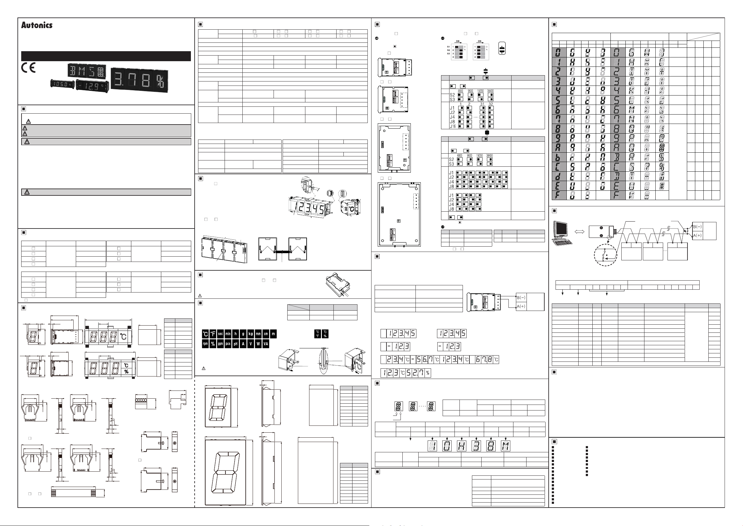
RS485 Slave Mode (Input Data Chart)
If there is no input data after supplying the power, the basic unit displays ‘T’.
DS Series (7-segment) DA Series (16-segment)
D5 D4 D5 D4 D5 D4 D5 D4 D5 D4 D5 D4 D5 D4 D5 D4 D5 D4
L L L H H L H H L L L H H L H H X X
n
0 G
u
1 H
'
•
2 I
2
3 J
3
4 K
5 L
5
6
6 M
n
7 N
'
8 O
8
9
9 P
R
A Q
B R
b
r
C S
L
d
D T
E U
E
F
F V
※
1: If this data is not for the unit-display unit, it maintains former state.
RS485 Slave Mode (Communication Setting)
1) Application of system organization
Comm. converter
Computer
2) Modbus Address Mapping
● Data format
Digit 1, 3, 5, ... 23 data
D7 D6 D5 D4 D3 D2 D1 D0
t I I I I i I I I I
● Display data
No. (Address) Func. R/W
400001 (0000) 03/06/16 R/W
400002 (0001) 03/06/16 R/W
400003 (0002) 03/06/16 R/W
400004 (0003) 03/06/16 R/W
400005 (0004) 03/06/16 R/W
400006 (0005) 03/06/16 R/W
400007 (0006) 03/06/16 R/W
400008 (0007) 03/06/16 R/W
400009 (0008) 03/06/16 R/W
400010 (0009) 03/06/16 R/W
400011 (000A) 03/06/16 R/W
400012 (000B) 03/06/16 R/W
400013 (000C) 03/06/16 R/W
400014 to 400050 03/06/16 R/W
Cautions during Use
1. Follow instructions in 'Cautions during Use'.
Otherwise, It may cause unexpected accidents.
2. 12-24VDC power supply should be insulated and limited voltage/current or Class 2, SELV power supply
device.
3. Install a power switch or circuit breaker in the easily accessible place for supplying or disconnecting the
power.
4. Keep away from high voltage lines or power lines to prevent inductive noise.
In case installing power line and input signal line closely, use line filter or varistor at power line and shielded
wire at input signal line.
Do not use near the equipment which generates strong magnetic force or high frequency noise.
5. This unit may be used in the following environments.
①
②
③
④
Photoelectric Sensors Temperature Controllers
Fiber Optic Sensors Temperature/Humidity Transducers
Door Sensors SSRs/Power Controllers
Door Side Sensors Counters
Area Sensors Timers
Proximity Sensors Panel Meters
Pressure Sensors Tachometers/Pulse (Rate) Meters
Rotary Encoders Display Units
Connector/Sockets Sensor Controllers
Switching Mode Power Supplies
Control Switches/Lamps/Buzzers
I/O Terminal Blocks & Cables
Stepper Motors/Drivers/Motion Controllers
Graphic/Logic Panels
Field Network Devices
Laser Marking System (Fiber, Co₂, Nd:YAG)
Laser Welding/Cutting System
DotUnit
Indoors (in the environment condition rated in 'Specifications')
Altitude max. 2,000m
Pollution degree 2
Installation category I
Major Products
■
■
■
■
■
■
■
■
■
W
X
Y
Z
-1
(
)
' I
" J
^ K
.
/ N
? O
- T
_
=
RS232C/
USB/Wi-Fi
,
ON OFF
'
I •
\
' ,
]
₩
H
(h)
K
X
Blank
RS485
0
..
0
...
--
B (-)
.......
__
A (+)
Data
Parameter
-
-
-
-
-
-
-
-
-
-
-
-
Reserved
0 G
1 H
2 I
3 J
4 K
5 L
6 M
7 N
8 O
9 P
A Q
B R
C S
D T
E U
F V
Terminating resistance
(100 to 120Ω)
A (+)
DEVICE
※
It is recommended to use Autonics communication converter;
...
SCM-WF48 (Wi-Fi to RS485·USB wireless communication converter,
sold separately), SCM-US48I (USB to RS485 converter, sold separately),
SCM-38I (RS232C to RS485 converter, sold separately).
Please use twist pair wire for RS485 communication.
Parameter name
Zero Blanking
Digit 1, 2 1, 2 display data
Digit 3, 4 3, 4 display data 0
Digit 5, 6 5, 6 display data 0
Digit 7, 8 7, 8 display data 0
Digit 9, 10 9, 10 display data 0
Digit 11, 12 11, 12 display data 0
Digit 13 14 13 14 display data 0
Digit 15, 16 15, 16 display data 0
Digit 17, 18 17, 18 display data 0
Digit 19 20 19 20 display data 0
Digit 21, 22 21, 22 display data 0
Digit 23, 24 23, 24 display data 0
A (+) A (+) B (-) B (-) B (-)
RS485
Digit 2, 4, 6, ... 24 data
RS485
DEVICE
#1
D7 D6 D5 D4 D3 D2 D1 D0
Description Setting range
Sett ng Zero Blanking ON/OFF
DU Series
High 2-bit
(unit)
No unit
]
W
Upper-Lower
OFF
[
X
Upper-Lower
ON
Y +
Upper ON
Z :
Lower ON
;
-1
Upper-Lower
ashes
(
<
Upper
ashes
)
>
Lower
ashes
|
'
" !
@
^
#
.
$
/
? %
- &
_
★
Blank
=
#2
I I I I I I I
※
Unit, point are displayed when it is ‘H’.
※
1
RS485
DEVICE
#30
D3 D2 D1 D0
L L L L
L L L H
L L H L
L L H H
L H L L
L H L H
L H H L
L H H H
H L L L
H L L H
H L H L
H L H H
H H L L
H H L H
H H H L
H H H H
0: OFF, 1: ON 0
Refer to input
data chart.
DRW170 316 AC
Low 4-bit
RS485
DEVICE
#31
Default
0
 Loading...