

Autonics D5Y Series, D5W Series Catalog Page
D5Y/D5W Series
5-digit Display Unit of DIN W72×36, W96×48mm Size
Features
● Various input specications
: Static Parallel input, Dynamic Parallel input, 4/5-bit serial input,
16/20/25-bit serial input method
● Decimal point, "-" minus sign display selection function
: Display type by serial input
Display type by external DP terminal and MINUS terminal
● Positive/Negative logic input selection function
● Display digit selection function
: 4-digit (-9999 to 9999), 5-digit (0 to 99999)
● Zero blanking function selection function
● Selectable reversion function of latch signal
Please read “Safety Considerations”
in the instruction manual before using.
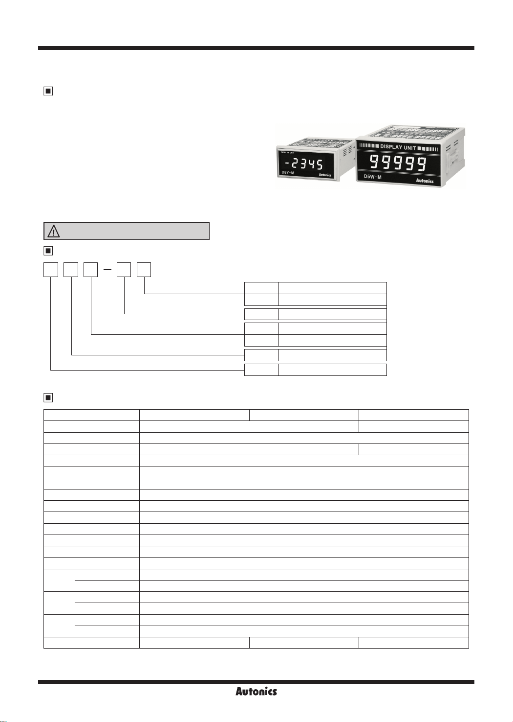
Ordering Information
D 5 W M X
111111
-=--=-----::c::...~-~~
------
■
DISPLAY UNIT
99999
---
DSW-M
■■
11111
Autonia
Power supply
Input
Size
Digit
Item
※
AC Power is only for D5W and it is op ion.
1:
Specifications
~
Model D5Y-M D5W-M D5W-MX
Power supply 12-24VDCᜡ 110/220VAC 50/60Hz
Allowable voltage range 90 to 110% of rated voltage
Power consumption Max. 1.1W Max. 2VA
Character size W7×H14mm
Display method 7-segment LED display (red)
Display digit Selectable 4-digit (or 4 ½ digit including symbol bit), 5-digit
Max. Clock 100Hz to 5kHz
Input logic Selectable positive (PNP) or negative (NPN)
Input me hod Static parallel, Dynamic parallel, 4/5-bit serial, Serial (16/20/25-bit)
Input level High: 5-24VDCᜡ, Low: 0-1.2VDCᜡ
Insulation resistance Over 100MΩ (at 500VDC megger)
Dielectric immunity 2,000VAC 50/60Hz for 1 min
Noise immunity ±1kV the square wave noise (pulse width: 1μs) by the noise simulator
Vibra ion
Shock
Environ
-ment
Unit weight Approx. 75g Approx. 165g Approx. 267g
※
※
Mechanical 0.75mm amplitude at frequency of 10 to 55Hz (for 1 min) in each X, Y
Malfunction 0.5mm amplitude at frequency of 10 to 55Hz (for 1 min) in each X, Y, Z direction for 10 minutes
Mechanical 300m/s² (approx. 30G) in each X,
Malfunction 100m/s² (approx. 10G) in each X, Y, Z direction for 3 times
Ambient temperature -10 to 50℃, storage: -25 to 65℃
Ambient humidity 35 to 85%RH, storage: 35 to 85%RH
Max. Clock is for 1:1 of duty ratio (ON, OFF ratio).
Environment resistance is rated at no freezing or condensa ion.
No-mark 12-24VDC
※
1
X
M Multi-input mode
Y DIN W72×H36mm
W DIN W96×H48mm
5 99999 (5-digit)
D Display Unit
110/220VAC 50/60Hz
J
Y, Z direction for 3 times
J
J
J
J
, Z direction for 1 hour
J
R-44
Autonics
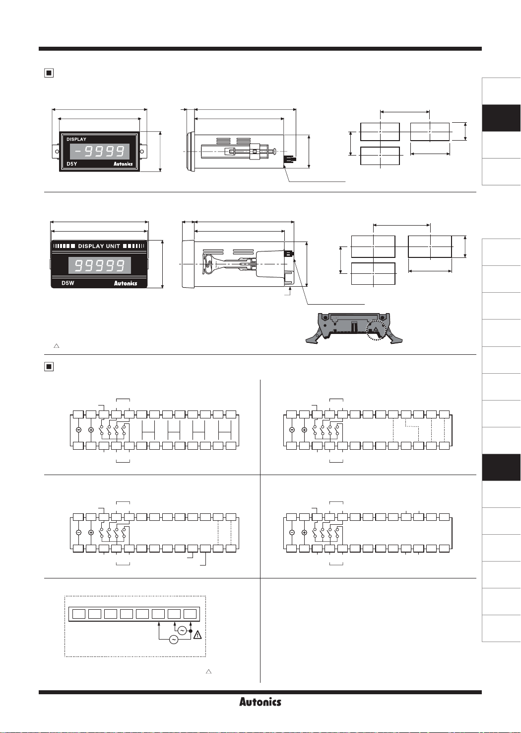
Dimensions
● D5Y-M
85
72
Panel Mount Type, 5-Digit Display Unit
0 5
67
0
(unit: mm)
0.5
0
31
● Panel cut-out
7
91
80
Min. 91
36
30
Min. 40
SENSORS
CONTROLLERS
MOTION DEVICES
● D5W-M/D5W-MX
98
96
※
Hirose connector pin header model: HIF3BA-26PA-2.54DS
※
Hirose connector socket is not included with this unit.
Contact hirose connector vendors for socket and cable.
[Socket: HIF3BA-26D-2.54R]
※
" mark indicates pin 1 of hirose connector.
"
12 99.5
90
48
※
When it is AC power option,
it is the terminal block for AC power.
Connections
● Static parallel input
Minus
26
● 4/5-bit serial input
Minus
26
● Power terminal for AC power option of D5W series
1 2 3 4 5 6 7 8
※
Above terminal connection diagrams's number set
by pin 1 of hirose connector. Please note that " "
mark indicates pin 1 of hirose connector.
10
+5VNC12-24VDC
10
+5VNC12-24VDC
DP
,----,
3
L__J
DP
DP
3
DP
1
C
10
3
10
2
D
10
1
10
2
10
220V 110V
2
10
D
LATCH
CLOCK
SOURCE
CC
10
D
0V
1
DOT
A
C
AAA
12345678910111213141516171819202122232425
0
10
B
BBB
D
A
C
12345678910111213141516171819202122232425
BCD
INPUT
B
D
Hirose connector
● Panel cut-out
Min. 112
45
[fu[J
Min. 50
1.
0.5
91
0
lj
Hirose connector
● Dynamic parallel input
Minus
3
10
10
2
+5VNC12-24VDC
10
DP
10
10
3
10
LATCH
10
1
DOT
ABC
12345
BCD
INPUT
67891011121314151617181920212223242526
2
0
10
D
DP
1
● Serial input
DP
1
Minus
26
※
In case of Static parallel input, 5-digit cannot be used
because of external terminal
※
To display 5 digit in Dynamic parallel, 4/5-bit serial, serial
input, display range is 0 to 99999 and it cannot display
minus sign. Therefore, the applied signal to the external
minus sign input terminal (pin 21) is ignored.
※
Regardless of input logic, connect external DP terminal
(pin 17, 18, 19) or external minus sign input terminal
(pin 21) to +5V (pin 20) and it displays decimal point and
minus sign.
3
10
10
19202122232425
18
2
10
+5VNC12-24VDC
DP
DATA NC
1234567891011121314151617
LATCH CLOCK
0.5
0
45
I
SOFTWARE
(J)
Temperature
Controllers
(K)
SSRs
(L)
Power
Controllers
(M)
Counters
(N)
Timers
(O)
Digital
Panel Meters
(P)
Indicators
(Q)
Converters
(R)
Digital
Display Units
(S)
Sensor
Controllers
(T)
Switching
Mode Power
Supplies
(U)
Recorders
(V)
HMIs
(W)
Panel PC
(X)
Field Network
Devices
Autonics
R-45

s,1uo1ny
R-46
tb: Min. 0.03ms
tw: Min. 0.02ms
}
ta: Min. 0.05ms
~ ~
tb: Min.0.03m
tw: Min. 0.02ms
}
ta: Min. 0.05ms
t3
2
1
N
N-1
N-2
1)x=x=x=>-
3
2
t t t t t t t t
C2
C1
CN
CN-1
CN-2
C3
))SV1--f7-
tb
ta
C2
0.2ms
1tr
Jl
tw
N-1
CN-1
~ ~
C1
1
N
CN
2
t t t t t t t t
C2
~
tb
ta
N-2
))x=x=x=>-
CN-2
))
3
C3
~
0.2ms
2
C2
1tr
u
Jl
tw
t3: Min. 0.05ms → Data latch
t2: Min. 0.1ms → Data move
t1: Min. 0.05ms → Data latch
}
Pw: Min. 0.2ms
t1
t2
LATCHLATCH
t3
Pw=t1+t2+t3
t2
C1
1
C1
1
t1
DATA
CLOCK
LATCH
● Negative logic (NPN) input: CLOCK Max. 5kHz
DATA
CLOCK
LATCH
● Positive logic (PNP) input: CLOCK Max. 5kHz
Serial input
@
")
Pw
22k
22k
1
l)I)@
22k5V22k
Input
~
Input dataInput data
Pw
● Negative logic (NPN) input
!1/
SIGNAL DISPLAY
NPN:
● Negative logic (NPN) input
• Low: 0-1.2VDC
• High: 5-24VDC
Input level
※
~)i
22k
22k
22k
1)1)
22k
Input
_r
● Positive logic (PNP) input
Parallel input
@
Input Timing
~
SIGNAL DISPLAY
PNP:
● Positive logic (PNP) input
Input Circuit
~
D5Y/D5W Series
 Loading...