

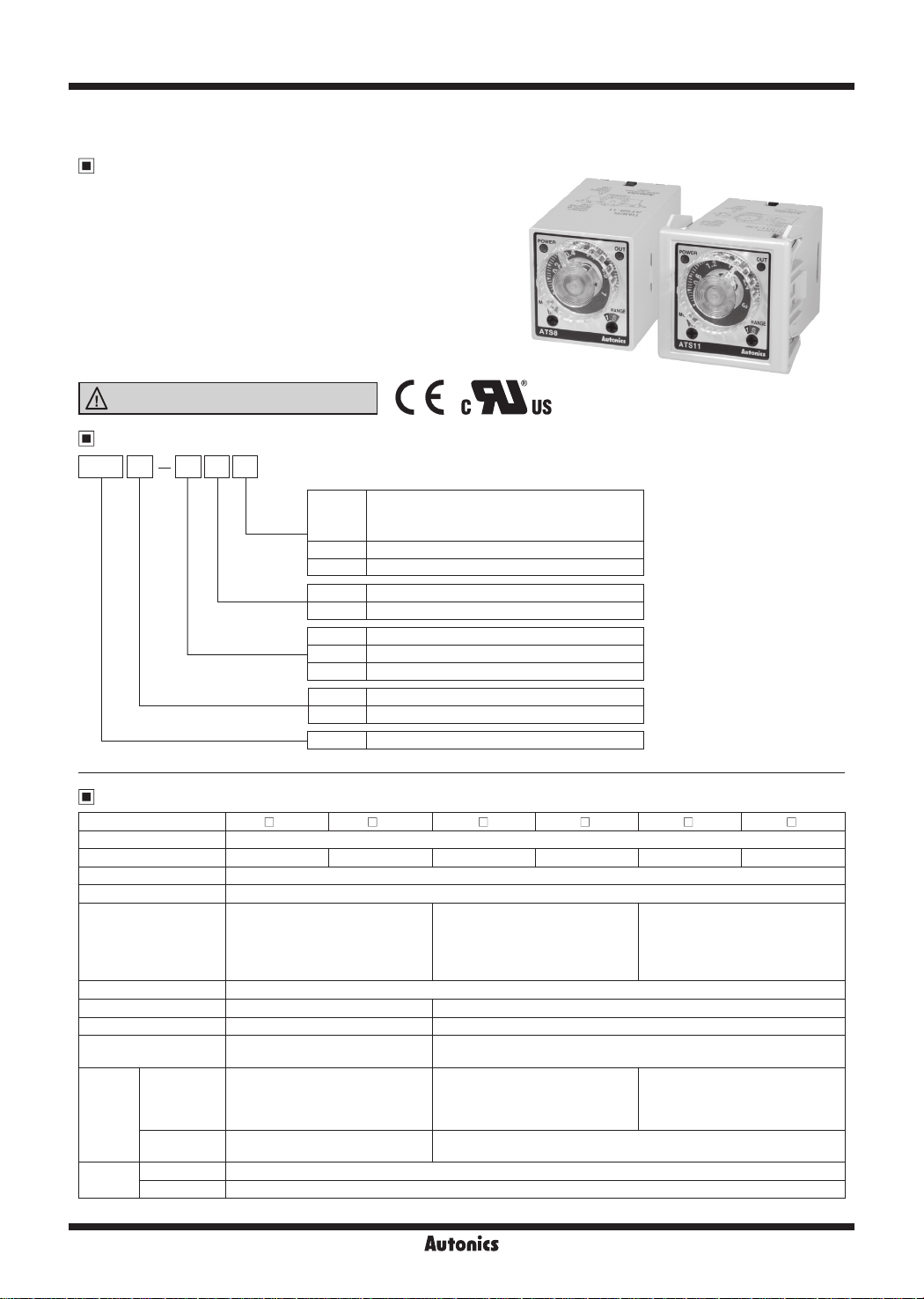
ATS Series
Multi Function Timer with Free Power, Compact Size W38×H42mm
Features
Wide power supply range
●
: 100-240VAC 50/60Hz, 24-240VDC universal,
24VAC 50/60Hz, 24VDC universal, 12VDC
Various output operations (6 operation modes)
●
Multi time range (12 types of time range)
●
Wide time setting range (0.1 sec to 30 hour)
●
Close and DIN rail mounting
●
with the dedicated socket (PS-M8) width 41mm (for ATS8)
Easy mounting and installation/maintenance
●
with the dedicated bracket for DIN 48×48
Please read “Safety Considerations”
in the instruction manual before using.
~l&
_____
Ordering Information
ATS 8 4 1
Item
※
8-pin socket (PG-08, PS-08(N), PS-M8) and 11-pin socket (PG-11, PS-11(N)) are sold separately.
I
II II
Time range
Power supply
Number of plug pins
I
Output
No mark
D Time limit DPDT (2c)
E Instantaneous SPDT (1c) + Time limit SPDT (1c)
1 Time range 1 (0.1 to 1)
3 Time range 3 (0.3 to 3)
1 12VDC
2 24VAC 50/60Hz, 24VDC
4 100-240VAC 50/60Hz, 24-240VDC
8 8-pin plug type
11 11-pin plug type
ATS Small Analog Timer
mm
I ( €
Time limit DPDT (2c) or
Instantaneous SPDT (1c) + Time limit SPDT (1c)
selectable by output operation mode
c'i\lus
-
'
Specifications
Model ATS8-
Function Multi Function Timer
Control time set ing range※10.1 sec to 10 hour 0.3 sec to 30 hour 0.1 sec to 10 hour 0.3 sec to 30 hour 0.1 sec to 10 hour 0.3 sec to 30 hour
Power supply •100-240VACᜠ 50/60Hz, 24-240VDCᜡ universal •24VACᜠ 50/60Hz, 24VDCᜡ universal •12VDCᜡ
Allowable voltage range 90 to 110% of rated voltage
Power consump ion
Return time Max. 100ms
Timing operation Power ON Start Signal ON Start
Min. input signal width
Input
Control
output
Relay life
cycle
※
N-48
Contact type
Contact capacity
Mechanical Min. 10,000,000 operations
Electrical Min. 100,000 operations (250VAC 3A resistive load)
1: Refer to time specications for control time setting range by model.
1 ATS8- 3 ATS11- 1D ATS11- 3D ATS11- 1E ATS11- 3E
□
I
□
□
I
□
□
I I I
•Max. 4.2VA (100-240VACᜠ),
Max. 2W (24-240VDCᜡ)
•Max. 4.5VA (24VACᜠ),
Max. 2W (24VDCᜡ)
•Max. 1.5W (12VDCᜡ)
-
-
Time limit DPDT (2c) or
Instantaneous SPDT (1c) +
Time limit SPDT (1c)
selectable by output operation mode
250VACᜠ 3A, 30VDCᜡ 3A
resistive load
•Max. 3.5VA (100-240VACᜠ),
Max. 1.5W (24-240VDCᜡ)
•Max. 4VA (24VACᜠ),
Max. 1.5W (24VDCᜡ)
•Max. 1W (12VDCᜡ)
START, INHIBIT, RESET: approx. 50ms
START, INHIBIT, RESET: [No-voltage input] - Short-circuit impedance: max. 1kΩ,
Residual voltage: max. 0.5VDC, Open-circuit impedance: min. 100kΩ
Time limit DPDT (2c)
250VACᜠ 3A, 24VDCᜡ 3A resistive load
•Max. 4.2VA (100-240VACᜠ),
Max. 2W (24-240VDCᜡ)
•Max. 4.5VA (24VACᜠ),
Max. 2W (24VDCᜡ)
•Max. 1.5W (12VDCᜡ)
Instantaneous limit SPDT (1c) +
Time limit SPDT (1c)
Autonics
I
□
SENSORS
CONTROLLERS
MOTION DEVICES
SOFTWARE
(J)
Temperature
Controllers
(K)
SSRs
(L)
Power
Controllers
(M)
Counters
(N)
Timers
(O)
Digital
Panel Meters
(P)
Indicators
(Q)
Converters
(R)
Digital
Display Units
(S)
Sensor
Controllers
(T)
Switching
Mode Power
Supplies
(U)
Recorders
(V)
HMIs
(W)
Panel PC
(X)
Field Network
Devices
Compact Multi Function Analog Timer
Specifications
Model ATS8-
Repeat error Max. ±0.2% ±10ms
SET error Max. ±5% ±50ms
Voltage error Max. ±0.5%
Temperature error Max. ±2%
Insulation resistance Over 100MΩ (at 500VDC megger)
Dielectric strength 2,000VAC 50/60Hz for 1 min
- 1
ATS
□
Noise
immunity
Vibration
Shock
Environment
DD
□
□
DD
- 4
DD
ATS - 2
ATS
Mechanical 0.75mm amplitude at frequency of 10 to 55Hz (for 1min) in each X, Y, Z direction for 1hour
Malfunction 0.5mm amplitude at frequency of 10 to 55Hz (for 1min) in each X, Y, Z direction for 10min
Mechanical 300m/s
Malfunction 100m/s
Ambient temp. -10 to 55℃, storage: -25 to 65℃
Ambient humi. 35 to 85%RH, storage: 35 to 85%RH
Approval
Accessory Bracket
※2
Weight
※2: The weight includes packaging. The weight in parenthesis is for unit only.
※Environment resistance is rated at no freezing or condensation.
1 ATS8- 3 ATS11- 1D ATS11- 3D ATS11- 1E ATS11- 3E
□
I
□
I
□
±500V the square wave noise (pulse width 1㎲) by noise simulator
±2kV the square wave noise (pulse width 1㎲) by noise simulator
2
(approx. 30G) in each X, Y, Z direction 3 times
2
(approx. 10G) in each X, Y, Z direction 3 times
ᜢ ᜧ
Approx. 95g (approx. 70g)
Connections
ATS8
●When selecting [A], [F]
output operation mode
4
3
2
(Time limit 1c)
1
5
6
7
8
CONTACT OUT
: 250VAC 3A,
30VDC 3A
RESISTIVE LOAD
(Time limit 1c)
●When selecting [A1], [B], [F1], [I]
output operation mode
(Instantaneous 1c) (Time limit 1c)
I
□
3
2
I
□
4
5
6
7
1
8
I
□
CONTACT OUT
: 250VAC 3A,
30VDC 3A
RESISTIVE LOAD
※
-
+
※
1: AC/DC voltage: 100-240VAC 50/60Hz, 24-240VDC
24VAC 50/60Hz, 24VDC
1
DC voltage: 12VDC
(Q)
ATS11-
D
□□
RESET
START
INHIBIT
6
5
4
3
2
7
8
9
10
1
11
CONTACT OUT
: 250VAC 3A,
24VDC 3A
RESISTIVE LOAD
(Time limit 1c) (Time limit 1c)
※
-
※
1: AC/DC voltage: 100-240VAC 50/60Hz, 24-240VDC
24VAC 50/60Hz, 24VDC
1
+
DC voltage: 12VDC
(Q)
ATS11-
(Instantaneous 1c)
Autonics
RESET
START
INHIBIT
E
□□
4
3
2
※
-
+
6
5
7
8
10
11
1
1
9
CONTACT OUT
: 250VAC 3A,
24VDC 3A
RESISTIVE LOAD
(Time limit 1c)
※
-
1
+
N-49
ATS Series
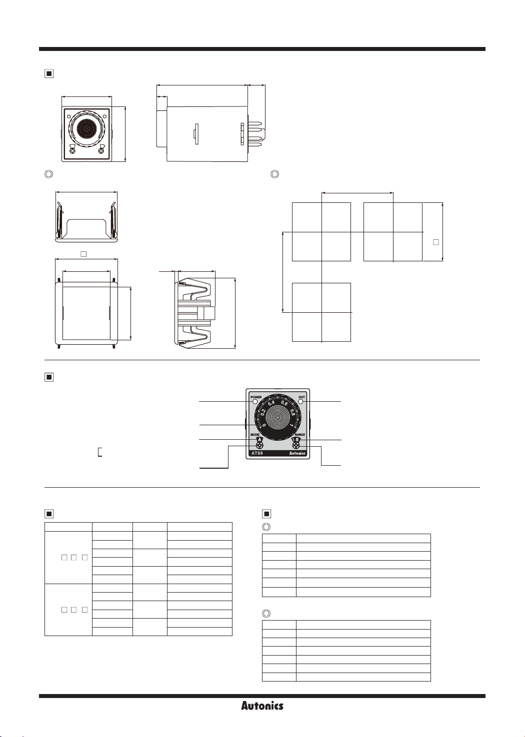
Dimensions
38.5 8
42.5
~
Bracket Panel cut-out
co
•
e
47.1
48
□
36.6 2.5 28.5
I
70 13.5
co
Min. 62
Min. 55
(unit: mm)
0
+0.6
45
□
40.6
•
•
Unit Description
Operation/Power indicator
(ashes for timer operation,
Turns ON for timer stop)
Time setting dial
Output operation mode indicator
ATS8: A, A1, B, F, F1, I mode
[
ATS11: A, F, F1, C, D, I mode
Output operation mode setting switch
Time Specifications
Model Time range Time unit Time setting range
- 1
ATS
□ □ □
ATS
- 3
□ □ □
1S
10S 1 to 10 sec
1M
10M 1 to 10 min
1H
10H 1 to 10 hour
1S
10S 3 to 30 sec
1M
10M 3 to 30 min
1H
10H 3 to 30 hour
SEC
MIN
HOUR
SEC
MIN
HOUR
0.1 to 1 sec
0.1 to 1 min
0.1 to 1 hour
0.3 to 3 sec
0.3 to 3 min
0.3 to 3 hour
54
Time limit output indicator
Time range indication
(1S, 10S, 1M, 10M, 1H, 10H)
Time range setting switch
Output Operation Mode
ATS8
Display Output operation mode
A Power ON Delay
A1 Power ON Delay 1 (One-Shot output)
B Power ON Delay 2
F Flicker (OFF Start)
F1 Flicker 1 (ON Start)
I Interval
ATS11
co
Display Output operation mode
A Signal ON Delay
F Flicker (OFF Start)
F1 Flicker 1 (ON Start)
C Signal OFF Delay
D Signal ON/OFF Delay
I Interval
N-50
Autonics

SENSORS
CONTROLLERS
MOTION DEVICES
SOFTWARE
(J)
Temperature
Controllers
(K)
SSRs
(L)
Power
Controllers
(M)
Counters
(N)
Timers
(O)
Digital
Panel Meters
(P)
Indicators
(Q)
Converters
(R)
Digital
Display Units
(S)
Sensor
Controllers
(T)
Switching
Mode Power
Supplies
(U)
Recorders
(V)
HMIs
(W)
Panel PC
(X)
Field Network
Devices
Compact Multi Function Analog Timer
Output Operation Mode (ATS8)
Mode Time chart
A
Power 2-7
Time limit contact N.C. 1-4 (8-5)
Power ON
Delay
A1
Power ON
Delay 1
(One-Shot
output)
Time limit contact N.O. 1-3 (8-6)
Time limit output indicator
Operation/Power indicator
Power 2-7
Time limit contact N.C. 8-5
Time limit contact N.O. 8-6
Instantaneous contact N.C. 1-4
Instantaneous contact N.O. 1-3
Time limit output indicator
Operation/Power indicator
Rt1 Rt1 t-at t
Rt1 Rt1 t-at t
0.5 sec 0 5 sec
※
One-Shot output is 0.5 sec xed.
[
t: Set ing time, t>t-a, Rt: Return time, Rt1>Rt
]
B
t
Power 2-7
Time limit contact N.C. 8-5
Time limit contact N.O. 8-6
Power ON
Delay 2
Instantaneous contact N.C. 1-4
Instantaneous contact N.O. 1-3
Time limit output indicator
Operation/Power indicator
F
t t
Power 2-7
Time limit contact N.C. 1-4 (8-5)
Flicker
(OFF Start)
Time limit contact N.O. 1-3 (8-6)
Time limit output indicator
Operation/Power indicator
F1
t
t t
Power 2-7
Time limit contact N.C. 8-5
Time limit contact N.O. 8-6
Flicker 1
(ON Start)
Instantaneous contact N.C. 1-4
Instantaneous contact N.O. 1-3
Time limit output indicator
Operation/Power indicator
I
t
Power 2-7
Time limit contact N.C. 8-5
Time limit contact N.O. 8-6
Interval
Instantaneous contact N.C. 1-4
Instantaneous contact N.O. 1-3
Time limit output indicator
Operation/Power indicator
※
In case of F, F1 output operation mode, setting time should be over 100ms.
If not, it may cause abnormal output operation due to under 100ms of setting time.
Autonics
Rt1
Rt1
Rt1
t
t
Rt1 t-a
t-a
N-51
t
Rt1
t-a
t-a
Rt1
t t
t
t

ATS Series
Output Operation Mode (ATS11)
Mode Time chart
A
Signal ON Delay
F
Flicker
(OFF Start)
Instantaneous contact N.C.
Instantaneous contact N.O.
Time limit output indicator
Operation/Power indicator
Instantaneous contact N.C.
Instantaneous contact N.O.
Time limit output indicator
Operation/Power indicator
Power 2-10
START 2-6
INHIBIT 2-5
RESET 2-7
Time limit contact N.C.
Time limit contact N.O.
Power 2-10
START 2-6
INHIBIT 2-5
RESET 2-7
Time limit contact N.C.
Time limit contact N.O.
F1
Power 2-10
START 2-6
INHIBIT 2-5
RESET 2-7
Flicker 1
(ON Start)
C
Signal OFF Delay
D
Signal ON/OFF
Delay
Time limit contact N.C.
Time limit contact N.O.
Instantaneous contact N.C.
Instantaneous contact N.O.
Time limit output indicator
Operation/Power indicator
Power 2-10
START 2-6
INHIBIT 2-5
RESET 2-7
Time limit contact N.C.
Time limit contact N.O.
Instantaneous contact N.C.
Instantaneous contact N.O.
Time limit output indicator
Operation/Power indicator
Power 2-10
START 2-6
INHIBIT 2-5
RESET 2-7
Time limit contact N.C.
Time limit contact N.O.
Instantaneous contact N.C.
Instantaneous contact N.O.
Time limit output indicator
Operation/Power indicator
I
Power 2-10
START 2-6
INHIBIT 2-5
RESET 2-7
Interval
※
ATS11-
※
If power is cut or the RESET terminal is short-circuited, the timer will be RESET.
※
If the INHIBIT terminal is short-circuited during a ime limit operation, the time will stop.
※
In case of F, F1 output operation mode, setting time should be over 100ms.
If not, it may cause abnormal output operation due to under 100ms of setting time.
E model only supports
□□
Time limit contact N.C.
Time limit contact N.O.
Instantaneous contact N.C.
Instantaneous contact N.O.
Time limit output indicator
Operation/Power indicator
Instantaneous contact.
t t1 t2
t t t t1 t2t-a
t t t t1 t2t-a
t
t t t
t t t
t-a
t-a t-a
t1
[
t: Setting ime, t=t1+t2, t>t-a
t2
t1
t2
t-a
t-a t-a
t1 t2t-a t-a
]
N-52
Autonics

SENSORS
CONTROLLERS
MOTION DEVICES
SOFTWARE
(J)
Temperature
Controllers
(K)
SSRs
(L)
Power
Controllers
(M)
Counters
(N)
Timers
(O)
Digital
Panel Meters
(P)
Indicators
(Q)
Converters
(R)
Digital
Display Units
(S)
Sensor
Controllers
(T)
Switching
Mode Power
Supplies
(U)
Recorders
(V)
HMIs
(W)
Panel PC
(X)
Field Network
Devices
Compact Multi Function Analog Timer
Proper Usage
Flicker mode
● Flicker mode which needs 3 subsidiary relays and 2
timers is available with an ATS timer.
You can organize flicker function economically.
● START it with a switch A and RESET it with a switch B.
START
RESET
R1
Timer
-
Interval mode
When using interval mode, you can simply organize
Instantaneous ON, Time limit OFF (self hold circuit).
START START
Time
limit
T
(existing wiring)
Conditions of input signal
(ATS11- D, ATS11- E)
1. Input with contact
Use a switch which is gilded and has good reliability of
contact.
Use a switch which has short bound(chattering) time for
input contact because bound(chattering) time of contact
timer may be error for operation time. Open resistance
should be over 100kΩ and short resistance should be
below 1kΩ.
※
Use contact which has good reliability to open/close for
0.4mA small current.
□□
< existing method >
R1 R1 R1
R2
Load
T1
< using icker mode of ATS >
~--------------
10
7
6
2
START RESET
A B
~ ~
T: Timer T: Timer (ATS8)
Instantaneous
contact
Load
R3
R2
T2
---
(using Interval mode)
□□
R3
Time
limit
T
R3T1
T2
Load
Load
2. Input with NPN open collector type
Characteristics of transistor should be Vceo = Min. 25V,
Ic = Min. 10mA, Icbo = Max. 0.2µA,
residual voltage = Max. 0.5V.
RESET
START
INHIBIT
+
+
+
6
7
5
2
INHIBIT
3. Input with NPN universal type
For non-contact circuit (proximity sensor, photoelectric
sensor, etc.) which output voltage range is 10-30VDC,
voltage output is also available as input signal not as
open collector output.
In this case, when signal changes from H to L, a timer
starts. Residual voltage should be below 0.5V when
transistor (Q) is ON.
10-30VDC
0.4mA
+
START
6
5
7
2
Time
limit
R
L
Q
Terminal connection
Refer to the connection diagrams and wire it correctly.
Power connection
For power connection of ATS Series, when it is AC
power, connect it to the designated power terminal
regardless of polarity. When it is DC power input after
checking polarity of power.
Power voltage 8-pin type 11-pin type
AC type Terminal ② - ⑦Terminal ② -
DC type
Turn OFF a power switch and be sure not to supply
•
induced voltage, residual voltage between timer power
Terminal ② Terminal ⑦ -
⊖
Terminal ② -
⊕
Terminal ⑩ -
terminals. (when wiring power cable parallel with high
voltage line, power line, induced voltage may occur
between power terminals.)
For DC power, ripple should be below 10% and power
•
voltage should be within the allowable range.
When applying the power to the Timer, please apply
•
the rated power at the moment by switch, relay, etc.
Otherwise it might cause malfunction.
Load for control output should be below the rated load
•
capacity.
RESET
START
+
+
5
+
6
7
2
⑩
⊖
⊕
Autonics
N-53

ATS Series
Changing of setting time, time range,
operation mode
It might cause malfunction if changing the setting time,
time range or operation mode during operating unit.
Please Change the setting time, time range or operation
mode after cut the power o.
(Q)
Input connection
Power circuit of ATS11- D/ATS11- E timer does
•
not use trans. Use isolation transformer which secondary
part is not grounded as (Figure 1) to cut o peripheral
current ow for supplied power to external input deivces.
(Figure 1)
Main circuit
<sensor>
As (Figure 2), if using terminal ⑩ as common terminal of
•
input signal, it may cause damage to inner circuit of
ATS11 timer. Use terminal
referring to (Figure 3).
(Figure 2)
INHIBIT
START
RESET
□□ □□
ATS11-
<extermal sensor power supply>
D/ATS11- E
□□
START
RESET
INHIBIT
Rectication
circuit
②
as common terminal
(Figure 3)
□□
Isolation
transformer
RESET
START
INHIBIT
Power
(Q)
Common
Be sure that when using a timer at high temperature for
•
a long time, it may cause deterioration for inner parts
(electrolytic condenser, etc.).
In case of 12VDC, 24VDC, 24VAC model, isolated and
•
limited voltage/current or Class 2 source should be
provided for power supply.
When supply the power to the Timer, connection shown in
•
(Figure 6) might cause malfunction due to leakage current
through R and C. Please connect R and C as shown in
(Figure 7) to prevent malfunction.
(Figure 6) (Figure 7)
Leakage
current
Power
Do not use this unit at below places.
•
• Place where there are severe vibration or impact.
• Place where strong alkalis or acids are used.
• Place where there are direct ray of the sun.
• Place where strong magnetic field or electric noise are
generated.
Installation environment
•
• Indoors
• Altitude Max. 2,000m
• Pollution Degree 2
• Installation Category
CR
T
Ⅱ
Timer
Power
R
C
T
Timer
Power
When controlling several timers by one input contact or
•
transistor, do not wire it as (Figure 4). This wiring causes
short current due to not accorded phase of power. Wire it
as (Figure 5) to accord to phase of power.
(Figure 4) (Figure 5)
Short
circuit
current
Power
In order to apply input signals (INHIBIT, START, RESET),
•
short-circuit the terminal no.
cause internal circuit damage by wrong connections.
Do not wire INHIBIT, START, RESET signal input line with
•
power line, high voltage line in parallel.
Use shield cable when input (INHIBIT, START, RESET)
•
cable is longer. Cable length should be as short as
possible.
N-54
Power
Power
②-⑤, ②-⑥
or
②-⑦
. It may
Autonics
 Loading...