

Autonics ATS8W Series, ATS11W Series Catalog Page
ATS8W/ATS11W Series
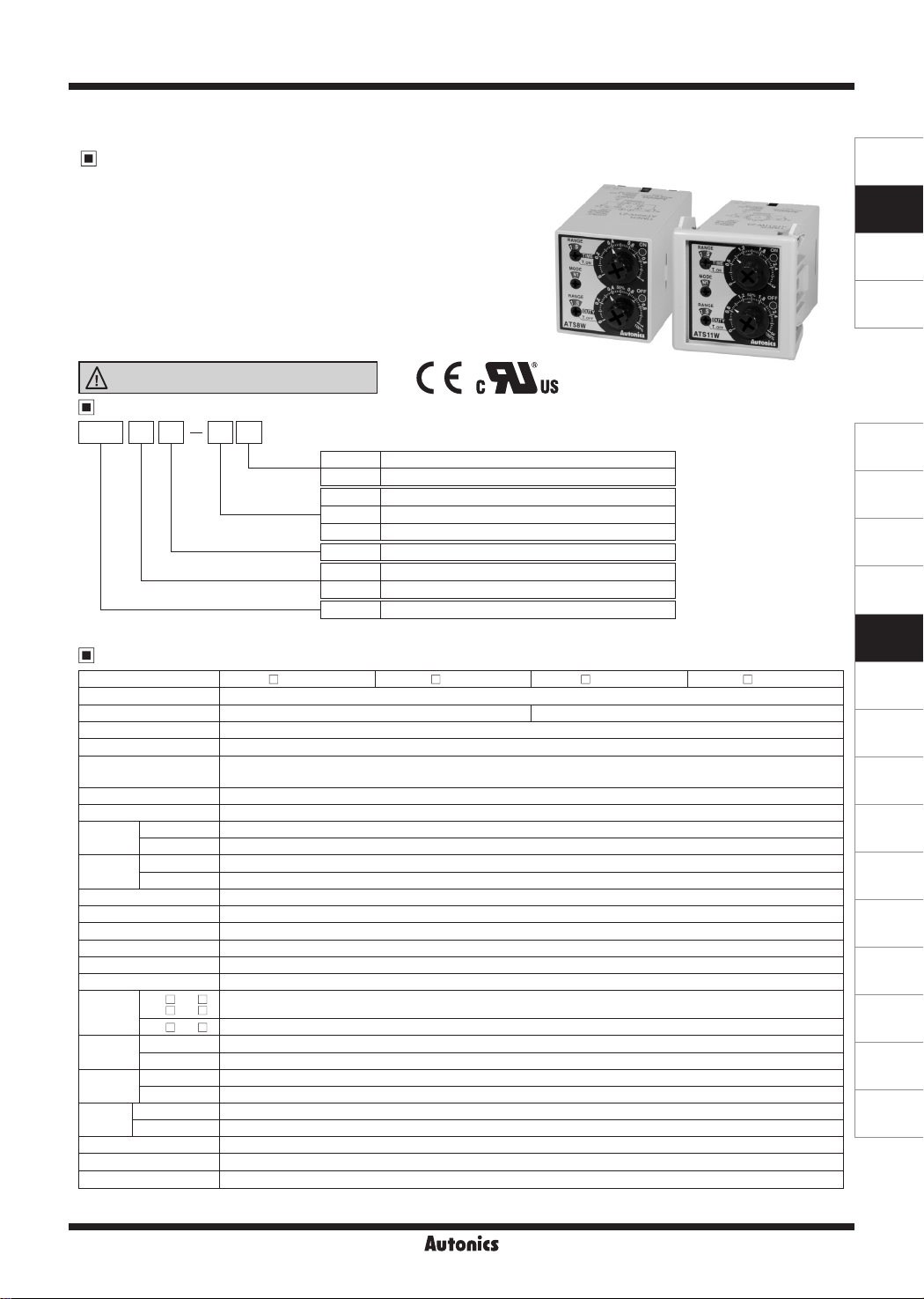
Twin Timer with Free Power, Compact Size W38×H42mm
Features
● Wide power supply range
: 100-240VAC 50/60Hz, 24-240VDC universal,
24VAC 50/60Hz, 24VDC universal, 12VDC
● Various output operations (6 operation modes)
● Multi time range (12 types of time range)
● Twin timer to set ON/OFF time individually
● Close and DIN rail mounting
with the dedicated socket (PS-M8) width 41mm (for ATS8W)
● Easy installation/maintenance with
the dedicated bracket for DIN 48×48mm
Please read “Safety Considerations”
in the instruction manual before using.
Ordering Information
ATS 8 W 4 1
Item
※
8-pin socket (PG-08, PS-08(N), PS-08) and 11-pin socket (PG-11, PS-11(N)) are sold separately.
Specifications
Model ATS8W-
Function ON/OFF Flicker operation
Control time set ing range
Power supply •100-240VACᜠ 50/60Hz, 24-240VDCᜡ universal •24VACᜠ 50/60Hz, 24VDCᜡ universal •12VDCᜡ
Allowable voltage range 90 to 110% of rated voltage
Power consumption
Return time Max. 100ms
Timing operation Power ON Start
Control
output
Relay life
cycle
Repeat error Max. ±0.2% ±10ms
SET error Max. ±5% ±50ms
Voltage error Max. ±0.5%
Temperature error Max. ±2%
Insulation resistance Over 100MΩ (at 500VDC megger)
Dielectric strength 2,000VAC 50/60Hz for 1 min
Noise
immunity
Vibration
Shock
Environment
Approval
Accessory Bracket
Weight
※
※
Ambient temp. -10 to 55℃, storage: -25 to 65℃
I
Ambient humi. 35 to 85%RH, storage: 35 to 85%RH
I
※
2
1: Refer to time specications for control time set ing range by model.
2: The weight includes packaging. The weight in paren hesis is for unit only. ※Environment resistance is rated at no freezing or condensation.
-
Time range
9
Power supply
Time operation
Number of plug pins
1 ATS11W- 1 ATS8W- 3 ATS11W- 3
□
※
1
0.1 sec to 10 hour 0.3 sec to 30 hour
•Max. 4.2VA (100-240VACᜠ), Max. 2W (24-240VDCᜡ) •Max. 4.5VA (24VACᜠ), Max. 2W (24VDCᜡ)
•Max. 1.5W (12VDCᜡ)
Contact type Time limit DPDT (2c) or Instantaneous SPDT (1c)+Time limit SPDT (1c) selectable by output operation mode
Contact capacity
250VACᜠ 3A, 3
Mechanical Min. 10,000,000 operations
Electrical Min. 100,000 operations (250VAC 3A resistive load)
ATS W-1
□
□
W-2
ATS
□
W-4 ±2kV the square wave noise (pulse width 1
ATS
□
Mechanical 0.75mm amplitude at frequency of 10 to 55Hz (for 1min) in each X, Y, Z direction for 1 hour
Malfunction 0.5mm amplitude at frequency of 10 to 55Hz (for 1min) in each X, Y, Z direction for 10 min
Mechanical 300m/s
Malfunction 100m/s
±500V the square wave noise (pulse width 1㎲) by noise simulator
□
□
2
(approx. 30G) in each X, Y, Z direction 3 times
2
(approx. 10G) in each X, Y, Z direction 3 times
ᜢ ᜧ
Approx. 100g (approx. 75g)
1 Time range 1 (0.1 to 1)
3 Time range 3 (0.3 to 3)
I I I
1 12VDC
2 24VAC 50/60Hz, 24VDC
4 100-240VAC 50/60Hz, 24-240VDC
W Twin (icker) operation
8 8-pin plug type
11 11-pin plug type
ATS Compact Analog Timer
I
□
I
□
I
0VDC
ᜡ 3A resistive load
) by noise simulator
㎲
I
□
Autonics
N-61
SENSORS
CONTROLLERS
MOTION DEVICES
SOFTWARE
(J)
Temperature
Controllers
(K)
SSRs
(L)
Power
Controllers
(M)
Counters
(N)
Timers
(O)
Digital
Panel Meters
(P)
Indicators
(Q)
Converters
(R)
Digital
Display Units
(S)
Sensor
Controllers
(T)
Switching
Mode Power
Supplies
(U)
Recorders
(V)
HMIs
(W)
Panel PC
(X)
Field Network
Devices

ATS8W/ATS11W Series
Connections
ATS8W
(Instantaneous 1c)
※
1
CONTACT OUT:
250VAC 3A, 30VDC 3A
RESISTIVE LOAD
※
1: When selecting [F2], [N2] output operation mode.
※
2: When selecting [F1], [F3], [N1], [N3] output operation mode.
Dimensions
00
※
2
(Time limit 1c)
38.5
42.5
4
5
3
2
6
7
1
8
(Time limit 1c)
※
+
-
6
3
68 13.5
ATS11W
6
5
(Instantaneous 1c)
※
1
CONTACT OUT:
250VAC 3A, 30VDC 3A
RESISTIVE LOAD
※
3: AC/DC voltage: 100-240VAC 50/60Hz, 24-240VDC
DC voltage: 12VDC
※
24VAC 50/60Hz, 24VDC
4
2
3
7
8
9
2
10
1
11
(Time limit 1c)(Time limit 1c)
※
-
+
3
(unit: mm)
Bracket
47.1
k::J
48
□
36.6 2 5 28.5
'-"
.
Unit Description
ON time/cycle range setting switch
Output operation mode display part
Output operation mode setting switch
.
..
.
40.6
,
.
ON time/cycle range display part
(F1, F2, F3, N1, N2, N3 mode)
OFF time range display part
OFF ime range setting switch
Panel cut-out
Min. 55
0
I
Min. 62
'
54
ON operation indicator (red)
ON time/cycle setting dial
OFF operation indicator (green)
OFF time/ON duty (%) setting dial
+0.6
45
□
Time Specifications
00
Model Time range Time unit Time setting range Model Time range Time unit Time setting range
ATS
N-62
W- 1
1S
10S 1 to 10 sec 10S 3 to 30 sec
'
1M
10M 1 to 10 min 10M 3 to 30 min
'
1H
10H 1 to 10 hour 10H 3 to 30 hour
-
-
SEC
MIN
HOUR
0.1 to 1 sec
0.1 to 1 min 1M
0.1 to 1 hour 1H
ATS W- 3
□ □ □ □
Auton1c
1S
. s
SEC
MIN
HOUR
0.3 to 3 sec
0.3 to 3 min
0.3 to 3 hour
 Loading...