

Autonics AT8SDN User Manual
DRW171150AA
STAR-DELTA TIMER
AT8SDN
I N S T R U C T I O N M A N U A L
Thank you very much for selecting Autonics products.
For your safety, please read the following before using.
Safety Considerations
Please keep these instructions and review them before using this unit.
※
Please observe the cautions that follow;
※
Warning
Caution
The following is an explanation of the symbols used in the operation manual.
※
Caution:Injury or danger may occur under special conditions.
Warning
1. Fail-safe device must be installed when using the unit with machinery that may
cause serious injury or substantial economic loss. (e.g. nuclear power control,
medical equipment, ships, vehicles, railways, aircraft, combustion apparatus, safety
equipment, crime/disaster prevention devices, etc.)
Failure to follow this instruction may result in re, personal injury, or economic loss.
2. Install on a device panel to use.
Failure to follow this instruction may result in electric shock or re.
3. Do not connect, repair, or inspect the unit while connected to a power source.
Failure to follow this instruction may result in electric shock or re.
4. Check ‘Connections’ before wiring.
Failure to follow this instruction may result in re.
5. Do not disassemble or modify the unit.
Failure to follow this instruction may result in electric shock or re.
Caution
1. Use the unit within the rated specications.
Failure to follow this instruction may result in re or product damage.
2. Use dry cloth to clean the unit, and do not use water or organic solvent.
Failure to follow this instruction may result in electric shock or re.
3. Do not use the unit in the place where ammable/explosive/corrosive gas, humidity,
direct sunlight, radiant heat, vibration, impact, or salinity may be present.
Failure to follow this instruction may result in re or explosion.
4. Keep metal chip, dust, and wire residue from owing into the unit.
Failure to follow this instruction may result in re or product damage.
Ordering Information
AT 8 SDN
※
The above specications are subject to change and some models may be discontinued
without notice.
※
Be sure to follow cautions written in the instruction manual and the technical descriptions
(catalog, homepage).
Serious injury may result if instructions are not followed.
Product may be damaged, or injury may result if instructions are not followed.
Operation
Plug Type
Item
SDN Star-Delta
8 8 Pin
AT Analog Timer
8 Pin socket(PG-08, PS-08) : Sold separately
※
Specications
Model AT8SDN
Function Star-Delta
Control time setting range 0.5 sec ~ 100 sec
Power supply 100-240VACᜠ 50/60Hz, 24-240VDCᜡ (Universal)
Allowable voltage range 90 ~ 110% of rated voltage
Power consumption 100-240VACᜠ : 3.2VA, 24-240VDCᜡ : 1.5W
Return time Max. 100ms
Control
output
Relay life
cycle
Repeat error Max. ±0.2% ±10ms
Setting error Max. ±5% ±50ms
Voltage error Max. ±0.5%
Temperature error Max. ±2%
- Switching time error Max. ±25%
Insulation resistance 100MΩ(at 500VDC megger)
Dielectric stength 2000VAC 50/60Hz for 1 minute
Noise strength
Vibration
Shock
Environ
-ment
Approval
Unit weight Approx. 90g
※
Environment resistance is rated at no freezing or condensation.
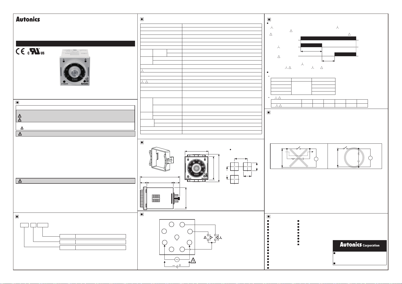
Dimensions
15
Connections
Type Contact : SPST(1a), Contact : SPST(1a)
Contact
Capacity 250VACᜠ 5A resistive load
Mechanical Min.10,000,000 times
Electrical Min. 100,000 times(250VAC 5A resistive load)
Square-wave noise by noise simulator,
apply ±2kV in power input terminals
Destruction
Malfunction
Destruction 300m/s²(Approx. 30G) 3 times at X, Y, Z direction
Malfunction 100m/s²(Approx. 10G) 3 times at X, Y, Z direction
Ambient temperature -10 ~ 55℃, Storage temperature: -25 ~ 65
Ambient humidity 35 ~ 85%RH, Storage humidity: 35 ~ 85%RH
80
50
3
2
0.75mm amplitude at frequency of 10 to 55Hz
in each of X, Y, Z directions for 1 hours
0.5mm amplitude at frequency of 10 to 55Hz
in each of X, Y, Z directions for 10 minutes
ᜢ ᜧ
48
15
4
5
6
7
8
1
SOURCE:
100-240VAC 50/60Hz
24-240VDC
℃
Panel cut-out
Min. 65
484555
Min. 65
CONTACT:
250VAC 5A RESISTIVE LOAD
+0.6
45
-0
(Unit:mm)
Operation and Time Specication
Operation
contact will be ON as soon as power is supplied, contact will be OFF when T1 setting
time is up then contact will be ON after T2 switching time is up.
contact will be OFF when cut off the power at the status of contact is ON.
Power(2-7)
Contact(5-8)
Contact(6-8)
T1 : Setting time( contact operation)
T2 : - Swtiching time( and contact are OFF when power is ON.)
Time specication
T1(Setting time)
Time range Time unit Time setting range
0.5
1.0 1 ~ 10 sec
5 5 ~ 50 sec
10 10 ~ 100 sec
T2(- Switching time)
Display A F F1 C D I
T2(- Switching time) 0.05 0.1 0.2 0.3 0.4 0.5
Cautions during Use
1. Follow instructions in ‘Cautions during Use’. Otherwise, It may cause unexpected
accidents.
2. When supplying or turning off the power, use a switch or etc. to avoid chattering.
3. Install a power switch or circuit breaker in the easily accessible place for supplying
or disconnecting the power.
4. In order to avoid leakage current owing, connect resistance and condenser as
(Figure 2).
If connect as (Figure 1), it may cause malfunction due to leakage current.
(Figure 1)
Power Timer
+0.6
45
-0
5. Keep away from high voltage lines or power lines to prevent inductive noise.
In case installing power line and input signal line closely, use line lter or varistor at
power line and shielded wire at input signal line.
Do not use near the equipment which generates strong magnetic force or high
frequency noise.
6. Change setting time(T1), Y-Δ switching time or etc. after turning off the power of the
timer.
7. This product may be used in the following environments.
Indoors (in the environment condition rated in ‘Specications’)
①
Altitude max. 2,000m
②
Pollution degree 2
③
Installation category II
④
×10 sec
Leakage
current
R C
T1
0.5 ~ 5 sec
T
T2
(Figure 2)
Power Timer
C
Major Products
Photoelectric Sensors Temperature Controllers
Fiber Optic Sensors Temperature/Humidity Transducers
Door Sensors SSRs/Power Controllers
Door Side Sensors Counters
Area Sensors Timers
Proximity Sensors Panel Meters
Pressure Sensors Tachometers/Pulse (Rate) Meters
Rotary Encoders Display Units
Connector/Sockets Sensor Controllers
Switching Mode Power Supplies
Control Switches/Lamps/Buzzers
I/O Terminal Blocks & Cables
Stepper Motors/Drivers/Motion Controllers
Graphic/Logic Panels
Field Network Devices
Laser Marking System (Fiber, Co₂, Nd: YAG)
Laser Welding/Cutting System
http://www.autonics.com
HEAD QUARTERS:
18, Bansong-ro 513 beon-gil, Haeundae-gu, Busan,
South Korea, 48002
TEL: 82-51-519-3232
E-mail: sales@autonics.com
[Unit: sec]
R
T
DR W17 1150 A A
 Loading...