

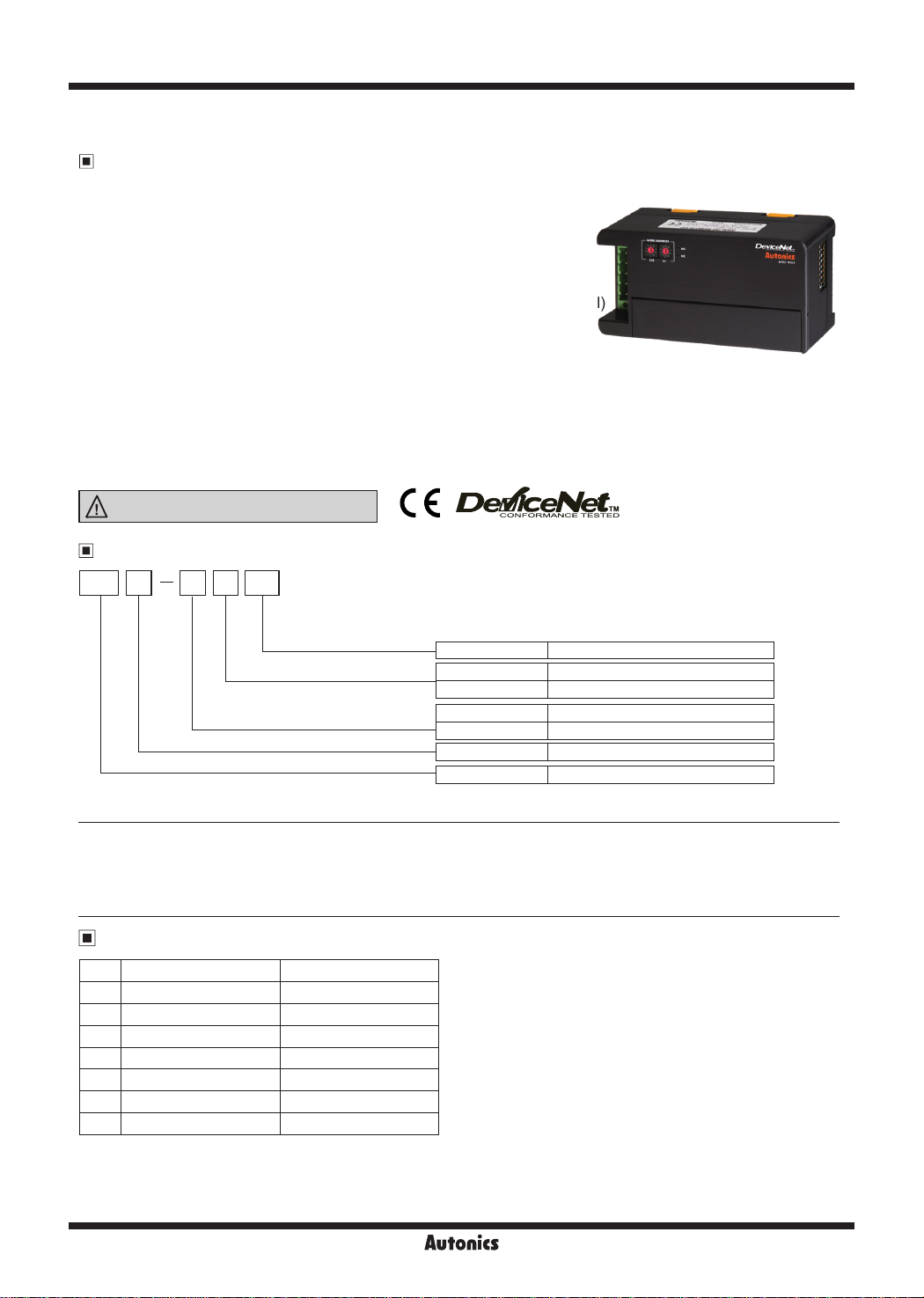
ARD-A Series
DeviceNet Analog Remote I/O
Features
● Adopts DeviceNet, standard open Network
: Communicates other DeviceNet devices without additional installations
: Configurable power and communication system only with
communication cables
: Connectable max. 63 units per 1 master unit
● Strong against noise and high accuracy (0.3%) measurement with
differential input method (measuring difference between +, - input signal)
● Various I/O range: 0-5VDC, 1-5VDC, 0-10VDC, -5-5VDC,
-10-10VDC, DC4-20mA, DC0-20mA
● Scale function: Settable high/low limit scale value for analog I/O range
(Setting range: -28,000 to 28,000)
● Various functions
: Automatic communication speed recognition, Network voltage monitoring, Input digital filter,
Peak/Bottom Hold, hysteresis, reading model name and number of units, I/O and status flag monitoring
● Built-in surge, ESD protection, Reverse polarity protection circuit
● Mounting DIN rail method and bolt mounting method
Please read “Safety Considerations”
in the instruction manual before using.
Ordering Information
AR D A
Digital/Analog
Network
Item
04I
I/O points
I/O type
(only for ARD-A 04,
other models are compatible)
04 4-point type
I Input type
O Output type
A Analog type
※
1
D
D DeviceNet type
AR Autonics Remote I/O
※
1. For digital type, refer to 'ARD-D Series'.
Digital type
Analog I/O Specications
No. I/O range Max. allowable I/O range
0 0-5VDC -0.25-5.25VDC
1 1-5VDC 0.8-5.2VDC
2 0-10VDC -0.5-10.5VDC
-
5-5VDC -5.5-5.5VDC
3
-
10-10VDC -11-11VDC
4
5 DC4-20mA DC3.2-20.8mA
6 DC0-20mA DC0-21mA
X-24
Autonics
DeviceNet Analog Remote I/O
Specifications
Model ARD-AI04 ARD-AO04
Power supply Rated voltage: 24VDCᜡ, Voltage range: 12-28VDC
Power consumption Max. 3W
I/O points
Volt age
Current DC4-20mA , DC0 -20mA (input impedance: 250Ω) DC4-20mA , DC0-20mA
Control
Max. allowable range
I/O
Resolu ion
Input 4-point
(switchable voltage/current)
0-10VDCᜡ, -10 -10VDCᜡ, 0-5VDCᜡ, 1-5VDCᜡ,
-5-5VDCᜡ
(input impedance: max. 1MΩ)
±5% F.S of rated input range ±5% F.S of rated output range
14bit, 1/16,000
Accuracy ● At room temperature (25±5℃) range: ±0.3% F.S. ● Out of room temperature range: ±0.6% F.S.
Insulation resistance Over 200MΩ (at 50 0VDC megger)
Noise immunity ±240V the square wave noise (pulse width: 1㎲) by the noise simulator
Dielectric strength 500VAC 50/60Hz for 1 min (bet ween external terminals and case, bet ween I/O and power terminals)
Vibration 1.5mm amplitude at frequency of 10 to 55Hz (for 1 min) in each X, Y, Z direction for 2 hours
Shock 500m/s
Ambient
temperature
Environment
Ambient
humidity
2
(approx. 50 G) in each X, Y, Z direction for 3 times
-10 to 50℃, storage: -25 to 75
℃
35 to 85%RH, storage: 35 to 85%RH
Protec ion structure IP20 (IEC standard)
Protec ion circuit Surge, ESD protection, reverse polarity protection circuit
Indicator Network status (NS) LED (green, red), unit status (MS) LED (green, red)
Material Front case, body case: Polycarbonate
Mounting DIN rail or bolt moun ing type
Isolation type I/O and inner circuit: non-insulated, DeviceNet and inner circuit: insulated, power and DeviceNet: insulated
Approval
※
1
Weight
※
Environment resistance is rated at no freezing or condensa ion.
※
1. The weight includes packaging. The weight in parentheses is for unit only.
DeviceNet Communication
00
I
C.
t
Detlfc:eNet
Approx. 210g (approx. 145g)
Item Specications
Communication
I/O Slave messaging (Group 2 Only slave)
● Poll command: Yes ● Bit_strobe command: Yes ● Cyclic command: Yes ● COS command: Yes
Communication distance Max. 500m (125kbps), Max. 250m (250kbps), Max. 100m (500kbps)
NODE ADDRESS setting Max. 64 nodes
Communication speed
※
1
125, 250, 500kbps (automatically set when connecting with Master)
Insulation I/O and inner circuit: Non-insulation, DeviceNetand inner circuit: Insulation, DeviceNet power: Insulation
Approval
※
1. The communication speed is automatically set to the communication speed of the Master (PC, PLC, etc.) When changing the
ODVA Conformance conformance: ARD-AI04
ODVA Conformance compatible : ARD-AO04
communication speed during operation, the network status (NS) LED ashes in red and communication is not possible.
ᜡ
Output 4 -point
(voltage 2CH, current 2CH)
0-10VDCᜡ, -10 -10VDCᜡ, 0-5VDCᜡ, 1-5VDCᜡ,
-5-5VDCᜡ (load resistance: max. 1kΩ)
(load resistance: max. 600Ω)
, DeviceNet compatible
I
C.
t
SENSORS
CONTROLLERS
MOTION DEVICES
SOFTWARE
(J)
Temperature
Controllers
(K)
SSRs
(L)
Power
Controllers
(M)
Counters
(N)
Timers
(O)
Digital
Panel Meters
(P)
Indicators
(Q)
Converters
(R)
Digital
Display Units
(S)
Sensor
Controllers
(T)
Switching
Mode Power
Supplies
Autonics
X-25
(U)
Recorders
(V)
HMIs
(W)
Panel PC
(X)
Field Network
Devices
ARD-A Series
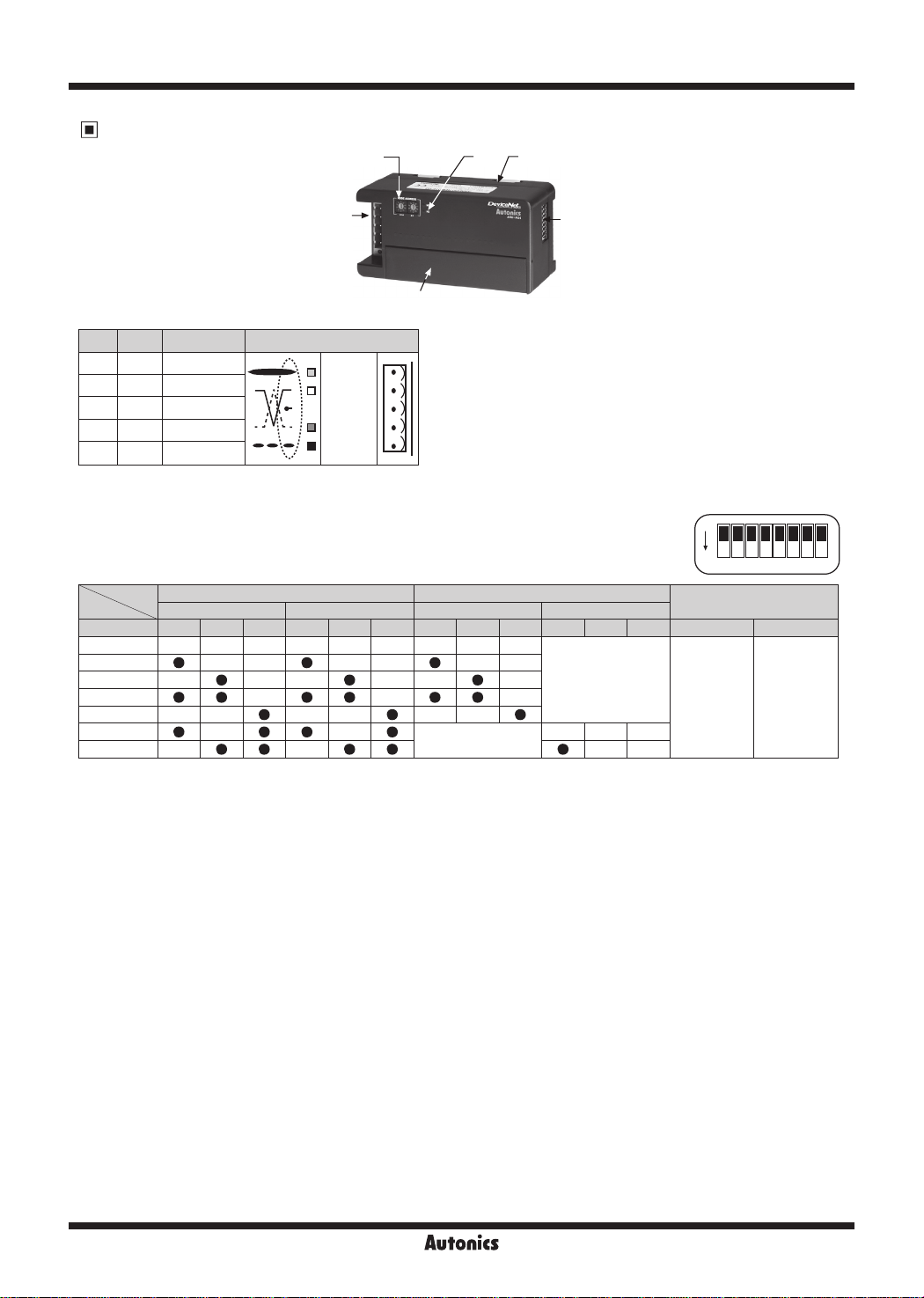
Unit Descriptions
2
3 4
1
1. DeviceNet connector
No.
Color
For Organization
5 Red 24VDC (+)
>----+----+---------<~\
4 White CAN_H
3 None SHIELD
f----+---+---------l
2 Blue CAN_L
>----+----+---------<
1 Black 24VDC (-)
2. Rotary switch for node address
X10 switch represents the 10’s multiplier and X10 switch represents the 1’s multiplier.
3. Status LED: It is LED for displaying Unit status (MS) and Network status (NS).
4. Rail Lock: It is used for mounting DIN rail or with bolt.
5. DIP switch: It is used for set I/O range. (factory default: all switches are OFF)
(●: ON, -: OFF)
~
I/O range SW1 SW2 SW3 SW4 SW5 SW6 SW1 SW2 SW3 SW4 SW5 SW6 SW7 SW8
0-5VDC
1-5VDC
0-10VDC
-5-5VDC
-10-10VDC
DC4-20mA
DC0-20mA
※
1: By turning ON SW8, I/O range is set by DIP switches (SW1 to SW6). By turning OFF SW8, I/O range is set by communication.
When setting I/O range by DIP switches, CH0 and CH1 (CH2 and CH3) cannot be set individually.
When setting it by communication, each channel is set individually.
6. I/O Terminal block: It is terminal block for connec ing external device I/O.
CH0, CH1 CH2, CH3 CH0, CH1 CH2, CH3
- - - - - - - - -
• • •
- - - - - -
• • • • • •
- - - - - -
• • • •
- - - -
-vv:
:\J.
-.
--\~/
ARD-AI04 (Input model) ARD-AO04 (output model)
- - - - - -
• • •
- - -
• • •
- -
• • • • •
V+
□
CAN_H
\D
SHIELD
..
• :
CAN_L
\"
-!
□
■
V-
: Two rotary switches are used for setting node address.
6
Not supported
5
I I
Not supported
- - -
I I
I I
ON
Not
supported
(O Setting)
1 2 3 4 5 6 7 8
ON
Using DIP
switch
OFF
Not using DIP
switch
1
※
X-26
Autonics

DeviceNet Analog Remote I/O
Status LED
~
※
Status of MS LED, NS LED
No. Type LED status Color Descriptions Troubleshooting
MS
1
NS Green
MS
2
NS
MS
3
NS Green
MS
4
NS
MS
5
NS
MS
6
NS
MS
7
NS
MS
8
NS
MS
9
NS
Dimensions
~
~
•
~
~
*
•
*
•
*
105
50
Green
Green
-
Green
Red
-
Red
-
Red
Green
Green
Red
Red
Red
Green
Red
Normal operation
I/O communication or message communication is
working.
Standby of duplicated address
The status of standby for receiving message of
duplicated address check from master unit.
Standby of normal operation
The status of standby for establish connection from
master unit.
Watchdog timer error
The status that DIP switch or another switch
setting is invalid.
Switch setting error
The status that DIP switch or another switch setting
is invalid.
Changed address during normal operation
The status that address is changed during normal
operation.
Invalid address
The status of setting invalid address
Duplicated address
There is duplicated address in the network.
Occuring Bus-O error
Communication is stopped with Bus-O.
I/O Connection time out
●
3-Ø4.5
Panel cut-out
( : ON, : Flash, : OFF)
~
-
-
-
Change the switch with valid
value and re-supply the power.
Change the switch setting to valid value
and re-supply the power.
Change the initial address at the power
applied at rst.
Change the valid address and re-supply
the power.
Change node address not duplicated.
Power on the slave unit again. Check
master unit, communication, cable,
terminating resistance and noise of
network.
Check the master setting and the user
program.
50 3-M4 Tap
i
i
____
_L_
__
_
5238.5
60.5
i
+~
60.5
~
•
(unit: mm)
SENSORS
CONTROLLERS
MOTION DEVICES
SOFTWARE
(J)
Temperature
Controllers
(K)
SSRs
(L)
Power
Controllers
(M)
Counters
(N)
Timers
(O)
Digital
Panel Meters
(P)
Indicators
(Q)
Converters
(R)
Digital
Display Units
35.3
Autonics
X-27
(S)
Sensor
Controllers
(T)
Switching
Mode Power
Supplies
(U)
Recorders
(V)
HMIs
(W)
Panel PC
(X)
Field Network
Devices

ARD-A Series
I/O Circuit Diagram
Type DeviceNet connector Inner circuit External connections
V
Analog
GND
V
V
V
AG
V.OUT
COM
I.OUT
COM
0
I
0
0
1
I
1
1
•
0
~□
~
Analog
input
Analog
output
CAN H
SHIELD
CAN L
CAN H
SHIELD
CAN L
V+
V-
V+
V-
(Q)
(Q)~~
(Q)~~
(Q)
(Q)
(Q)
(Q)
(Q)
(Q)
(Q)
~----------i
,--------,--------
~~
c---------c-,.--------,
c---------,-,-----,
r------c-1-----,
~-----,
f---------,-J------.-----,
Inner circuit
Power circuit
Inner circuit
Power circuit
Input circuit
Power circuit
Output circuit
Power circuit
Analog
GND
V
mA
Load
Max. 1KΩ
Load
Max. 600Ω
□
Connections
※
When wiring the communication connector, use cable and tap which meet the DeviceNet standard
and tighten the connector screw with a tightening torque of 0.5N.m.
※
When wiring the input/output terminal, tighten the connector screw with a tightening torque of 0.5N.m.
ARD-AI04
l
V
I
0
0
V
AG
0-
~
I I I I I I I I I
V
※
1: For current input, short between V
Terminating Resistance
1
※
Short
V
I
1
V
1-
·5·
mA
I
V
2
1
2
V
AG
AG
2-
111111
I
V
3
3
V
AG
3-
□+
N C
N.C
and I□+.
N C
N.C
ARD-AO04
l
V
V
0
1
COM
COM
·is
I
I I I I I I I I I
V
N.C
I
I
0
1
COM
lY
N C
COM
I I I I I I
mA
N.C
N C
N C
N.C
N C
N C
N C
N C
N.C
N C
Voltage
Current
0-5VDC
1 to 5VDC
-5-5VDC
0-10VDC
-10-10VDC
DC0-20mA
DC4-20mA
● 120Ω ● 1% of metallic lm ● 1/4W
※
Do not install terminating resistance on ARD unit or it may cause network problem (impedance can be too high or low)
or malfunction.
※
Connect terminating resistance on the both ends of the trunk line.
Communication Distance
Baud Rate Max. network length
125kbps 500m 6m 156m
250kbps 250m 6m 78m
500kbps 100m 6m 39m
Max. length of
branch line
Allowable expansion
length of branch line
X-28
Autonics

DeviceNet Analog Remote I/O
Setup and Installation
Node address setup
Two rotary switches are used for setting node address.
①
X10 switch represents the 10’s multiplier and X10 switch represents the 1’s multiplier.
Node address is settable from 0 to 63.
Node address is changed when re-supplying the power to the unit.
②
After changing node address, must re-supply the power.
※
The address of the connected unit must not be duplicated.
When changing the address during operation, the unit status (MS) LED ashes in red and the unit communicates to
the address before the change.
Installation
●
Mounting on panel
Pull Rail Locks (3) on the rear part of a unit,
①
there are xing bolt hole.
Place the unit on a panel to be mounted.
②
Make a hole on a xing bolt position.
③
Fasten the bolt to x the unit tightly.
④
Tightening torque should be below 0.5N.m.
●
Mounting on DIN rail
Pull two Rail Locks on the rear part of unit.
①
Place the unit on DIN rail to be mounted.
②
Press Rail Locks to x the unit tightly.
③
I/O cable connection
Refer to '
Connect a sensor or the signal cable of external I/O device to the terminal block. (tightening torque: 0.5N.m)
I/O circuit diagram and connections'.
DeviceNet cable connection
For stable system, it is recommended to use the DeviceNet dedicated cable.
①
Connect the DeviceNet cable to the DeviceNet connector and tighten the xed bolt of the connector by a driver.
②
(tightening torque: 0.5N.m)
Connect the DeviceNet connector to ARD unit and supply the power to Network.
③
Master unit
PIN No. Signal
5 V+
4 CAN_H
3 SHIELD
2 CAN_L
1 V-
Red
White
None
Blue
Black
ARD unit
PIN No. Signal
5 V+
4 CAN_H
3 SHIELD
2 CAN_L
1 V-
5 (Red): V+
4 (White): CAN_H
3 (None): SHIELD
2 (Blue): CAN_L
1 (Black): V-
E . g . )
The X10 and X1 switches point "3",
the address is "33".
SENSORS
CONTROLLERS
MOTION DEVICES
SOFTWARE
(J)
Temperature
Controllers
(K)
SSRs
(L)
Power
Controllers
(M)
Counters
(N)
Timers
(O)
Digital
Panel Meters
(P)
Indicators
(Q)
Converters
(R)
Digital
Display Units
Setting of master unit
Check the LED status of ARD unit when power is supplied. Normal operation is below.
①
Type Status LED Status descriptions
Unit status (MS) LED Green LED is ON
Network status (NS) LED Green LED is ON/ashes
Install the software provided by master unit manufacturing company.
②
Set communication speed and address in the software.
③
When master unit status is communication standby: NS LED ashes
When master unit setting is completed: NS LED is ON.
● Baud rate: 125/250/500kbps
● Address of master unit: Usually it is set 00 address.
Register connected unit on Network to the master unit.
④
● There are two ways to register units; automatically register in on-line or manually register in off-line.
(Refer to the manual of master unit.)
● I/O assignment of ARD Series: Usually it is automatically assigned by the setting software.
● Setting of operation mode: Select among Poll, COS, Cyclic, Bit Strobe. (Usually set Poll mode.)
Check operating stauts
When installation and setting are complete, unit status (MS) LED and Network status (NS) LED turn ON green.
(Refer to ' Status LED'.)
Autonics
X-29
(S)
Sensor
Controllers
(T)
Switching
Mode Power
Supplies
(U)
Recorders
(V)
HMIs
(W)
Panel PC
(X)
Field Network
Devices

ARD-A Series
Functions
Model
Com. speed auto-recognition
Network power voltage monitoring
Unit power on total time monitoring
Basic
Unit comment
Last maintenance data stored
Scaling
I/O comment
Adjustment gradient
Adjustment oset
Input conversion points setting
Input digital lter
Analog
Peak/Bottom hold
Disconnected cable detection
Input comparison
Hysteresis
Output setting for error
Communication speed auto-recognition
It recognizes communication speed when connecting
master. Communication speed is able to change only from
master unit.
After changing communication speed, re-supply the
network power to apply the changed communication
speed.
Network power voltage monitoring
● If
network power voltage is lower than the set value, the
network power voltage drop flag bit of Status bit is ON.
It can be read by Configurator or Explicit message.
●
Set monitoring voltage by Explicit message at Network
Power voltage (Set Value) of Application Object.
●
Setting range: 0 to 255
(factory default: 12V, Allowable range: ±1V)
※
Min. supplied power is 12V for ARD unit.
If network voltage is lower than 12V, the contents of
Explicit message reading is not guaranteed.
Unit power on total time monitoring
●
When total time for supplying power to the unit
becomes the SV, Threshold Run Hours Flag bit of
Status Bit turns ON. It can be read by Configurator or
Explicit message.
●
Set the time by Explicit message at Threshold Run
Hour of Application Object.
●
Setting range: 0 to 429,496,729 hours
(factory default: 876,000 hours),
Measured unit: 0.1 hours (6 minutes)
Unit comment
● You can set the comments for the unit (product
description) on network. It can be read by Configurator
or Explicit message.
● Set comment by Explicit message at Unit Comment of
Application Object.
● Setting range: max. 32 characters
ARD-AI04
(input model)
ARD-AO04
(output model)
•
•
•
•
•
•
•
•
•
•
•
•
•
•
•
-
Last maintenance date
●
It saves the last date of maintenance. It can be read/
written by Configurator or Explicit message.
●
Set maintenance date by Explicit message at I/O Last
Maintenance Data Setting of Analog Input Point Object.
E.g.) Data: 0x07DB020E→07DB (2011), 02 (Februray),
0E (14th)
Input conversion points setting
● Conversion cycle is changed by the number of points
(point, channel).
(conversion cycle: 1ms/point, when using 4 points,
it is 4ms). It can be read/written by Configurator
or Explicit message. After changing the number of
conversion points, re -supply the network power.
● Set the number of conversion points by Explicit
message at Number of AD Conversion Points Setting
of Analog Input Point Object.
● Setting range: 1 to 4-point (factory default: 4-point),
conversion cycle: 1ms/1-point
Display scale
● Set high/low-limit scale value of analog input or output.
It can be read by Configurator or Explicit message.
It is set as 1,000 per 1V (mA).
In case of 1-5V, 4-20mA, it is
applied from over min. allowable
range 0.8V (800), 3.2 (3,200).
The below input value is break
detec ion. It outputs as min.
allowable range.
It is set as default value 0 to
16000 (-8000 to 8000).
(0-5V, 1-5V, 0-10V, 4-20mA,
0-20mA: 0 to 16000, -5-5V, -1010V: -8,000 to 8,000 )
Set high/low-limit value to apply
at ‘Scaling Point 0%’ and ‘Scaling
Point 100%’.
Setting range: -28,000 to 28,000
Default
Scaling
None
Scaling
User
Scaling
Function Choice
: Scaling Flag bit ON
Scaling Type
: Default Scaling
(factory default)
Function Choice
: Scaling Flag bit
OFF
Scaling Type
: Default Scaling
Function Choice
: Scaling Flag bit ON
Scaling Type
: User Scaling
-
-
-
-
-
-
•
X-30
Autonics

DeviceNet Analog Remote I/O
(Q)
I/O comment
● You can set the comment for I/O. It is able to read/
write by Configurator or Explicit message.
● Set I/O comment by Explicit message at I/O Comment
of Analog Input Point Object, Analog Output Point
Object.
● Setting range: max. 32 characters
(Q)
Gradient adjustment
● It adjusts the gradient of input/output value or scale
value. It is able to read/write by Configurator or Explicit
message.
● It is applied when Adjust Gradient Flag bit is set as ON
at Function Choice of Analog Input Point Object. Set
the range at Adjustment Gradient value.
● Adjustment range: -5 to 5%,
Setting range: -500 to 500 (factory default: 0)
E.g.) When input value is 1000, Adjustment Gradient is
500 (+5%) X’=aX, a=1+Adjustment Gradient (0.05),
X=1000, X’=1.05×1000=1050
(Q)
Oset adjustment
●
This function is to adjust the error occurring from
external analog sensor, etc, not from the unit itself. It is
also applied to analog output. It is able to read/write by
Configurator or Explicit message.
●
It is applied when Adjustment Offset Flag bit is set as
ON at Function Choice of Analog Input Point Object.
Set the value at Adjustment Offset Value.
●
Adjustment range: -5 to 5%,
Setting range: -500 to 500 (factory default: 0)
E.g.) When input range is 0 to 10V, Full Scale 0 to 16000,
input value is 1600 (1V) and Adjustment Gradient
500 (+5%), X’=X+b, X=1600, b=16000×0.05
(added input value and percentage of Full Scale)
X’=1600+800=2400 (1.5V)
(Q)
Input digital lter
●
This function is used when input value vibrates or
repeatedly shake by included noise at input signal.
Accurate control is available by stable input with this
function. It adopts moving average filter method not
to affect sampling cycle. It is able to read/write by
Configurator or Explicit message.
●
It is applied when Moving Average is set as ON at
Function Choice of Analog Input Point. Set the number
of digital filters at Moving Average Filter of Number.
●
Setting range: 0 to 8
(factory default: 3[Moving Average No_8])
Input min./max. value save
● Min./Max. save when power is ON
It saves min./max. input value from power ON the network.
(When network power is OFF, the saved min./max. input
value are cleared.)
It is able to read by Configurator or Explicit message.
When Clear Max, Clear Min Flag bit of is ON at Function
Choice of Analog Output Point Object, the saved values
are cleared and it saves current min./max. value of
current input.
● Min./Max. save when Peak/Bottom Hold signal
is ON
It memorizes the max./min. value while Peak/Bottom
signal is ON. When Peak /Bottom signal is OFF, they are
saved.
It is able to read by Configurator or Explicit message.
It is applied when Peak/Bottom is set as ON at Function
Choice of Analog Input Point Object. You can check the
value of Peak/Bottom at Peak Value and Bottom Value.
Max.
value
Input
Analog
input
Peak/
ON
Bottom
hold signal
OFF
ON
Network
OFF
power
(Q)
Disconnection detection
●
When operating analog input cable (voltage/current
input) is disconnected, Broken Wire Flag Bit turns
ON at Analog Status Flag Read of Analog Input Point
Object. (It operates only for 1-5V, 4-20mA input range.)
It is able to read by Configurator or Explicit message.
●
If this value is below -5%, it recognizes disconnection
and displays ‘32767’ as data value.
(Q)
Input comparison
●
It compares analog input value or the operation value
and alarm set value (HH, H, L, LL) and Analog Status
Bit flag turns ON at Function Choice of Analog Input
Point Object. It is able to read by Congurator or
Explicit message.
●
If the value is within the setting range between ‘H’ and
‘L’, it is available to apply by turning ON Pass Signal
Flag bit at Analog Status Flag Read of Analog Input
Point Object and turning ON/OFF Comparator Flag bit
at Function Choice.
HH
H
L
LL
HH alarm
H alarm
Normal Flag
L alarm
LL alarm
Peak/Bottom Hold value monitoring
Peak Hold value
Bottom Hold value
Min. value
Time
SENSORS
CONTROLLERS
MOTION DEVICES
SOFTWARE
(J)
Temperature
Controllers
(K)
SSRs
(L)
Power
Controllers
(M)
Counters
(N)
Timers
(O)
Digital
Panel Meters
(P)
Indicators
(Q)
Converters
(R)
Digital
Display Units
(S)
Sensor
Controllers
(T)
Switching
Mode Power
Supplies
(U)
Recorders
(V)
HMIs
(W)
Panel PC
(X)
Field Network
Devices
Autonics
X-31

ARD-A Series
(Q)
Hysteresis
●
In case of comparison output, this function is to increase
stability of comparison output against v bration of input
signal or chattering.
It is able to read by Congurator or Explicit message.
●
It is applied when Compare Bit flag turns ON at Function
Choice of Analog Input Point Object.
Set the value at Hysteresis Value.
●
Setting range: 0 to 16,383 (factory default: 0)
(Q)
Output value setting for com. error
●
When communication error occurs, this function is to
set output value of output unit by each channel. It is
able to read by Configurator or Explicit message.
●
Set Fault state at Fault Action of Analog Output Point.
●
Setting range: 0 to 3 (factory default: 1)
0: Hold Last State-maintains the last status
2: High Limit-outputs max. value
1: Low Limit-outputs min. value
3: Zero Count-outputs 0%
Assembly Instance ID Assignment
00
(Q)
Produced I/O assignment (Input)
It is available to assign I/O data by the selected data at master. When changing Produced I/O data assignment, re-supply
the network power of ARD unit to apply the changed assignment.
Status ag monitoring
●
When the net work power voltage is lower than the
set value or unit operation time is over the set value,
monitoring is available by Status Bit of Application
Object.
It is able to read by Congurator or Explicit message.
※
Flag Bit
Bit 0: Reserved
Bit 1: Network Power Voltage Drops
(below the set level)
Bit 2: Life State (Unit)
Bit 3: Reserved
Bit 4: Reserved
Bit 5: Reserved
Bit 6: Reserved
Bit 7: Reserved
(Q)
Analog data allotment
●
This function is to allot analog data. Select the desired
data to transmit it to the master unit. It is able to read
by Congurator or Explicit message.
●
Set the allotment at Analog Data 1/2 Allocation
selection of Analog Output Point.
●
Setting range: 0 to 2 (factory default: 0)
0: Analog Input Value
1: Peak Value
2: Bottom Value
1) Analog Data1 (Default I/O Data)
Analog Data 1 is assigned as Produced I/O data by Congurator or Explicit message. By property setting, assignment is
available as Analog Input Value, Peak Value, Bottom Value.
● Assembly Instance ID: 103, ● Default: 0
● Setting range: 0 to 2 (Analog Input Value: 0, Peak Value: 1, Bottom Value: 2)
● Data type: Word, Data size: 4Word
15 0
Assigned value to Analog Data 1 of Input point 0
Assigned value to Analog Data 1 of Input point 1
Assigned value to Analog Data 1 of Input point 2
Assigned value to Analog Data 1 of Input point 3
015
2) Analog Data2
Analog Data 2 is assigned as Produced I/O data by Congurator or Explicit message. By property setting, assignment is
available as Analog Input Value, Peak Value, Bottom Value.
● Assembly Instance ID: 104 ● Default: 0
● Setting range: 0 to 2 (Analog Input Value: 0, Peak Value: 1, Bottom Value: 2)
● Data type: Word, Data size: 4Word
15 15
Assigned value to Analog Data 2 of Input point 0
Assigned value to Analog Data 2 of Input point 1
0 0
Assigned value to Analog Data 2 of Input point 2
Assigned value to Analog Data 2 of Input point 3
3) Generic Status
Generic Status is assigned as Produced I/O data by Congurator or Explicit message.
● Assembly Instance ID: 100 ● Data type: Byte, Data size: 1Byte
● Generic Status
Bit 0: Reserved.
Bit 1: Network Power Voltage Drops.
Bit 2: Life State (Unit)
15
-
X-32
Bit 3: Reserved.
Bit 4: Reserved.
Bit 5: Reserved.
0
Generic Status
Autonics
Bit 6: Reserved.
Bit 7: Reserved.

DeviceNet Analog Remote I/O
4) Analog Status
Analog Status is assigned as Produced I/O data by Congurator or Explicit message.
● Assembly Instance ID: 105 ●Data type: Byte, Data size: 4Byte
● Analog Status
Bit 0: Low Alarm (LL)
Bit 1: Low Warning (L)
Bit 2: Pass Signal (Nomal)
15 0
Analog Status of Input point 1 Analog Status of Input point 0
Analog Status of Input point 3 Analog Status of Input point 2
5) Analog Data1+Analog Data2
Analog Data 1 + Analog Data 2 is assigned as Produced I/O data by Congurator or Explicit message. By property setting,
assignment is available as Analog Input Value, Peak Value, Bottom Value.
● Assembly Instance ID: 106 ● Default: 0
● Setting range: 0 to 2 (Analog Input Value: 0, Peak Value: 1, Bottom Value: 2)
● Data type: Word, Data size: 8Word
15 150 0
Assigned value to Analog Data 1 of Input point 0
Assigned value to Analog Data 2 of Input point 0
Assigned value to Analog Data 1 of Input point 1
Assigned value to Analog Data 2 of Input point 1
6) Analog Status+Generic Status
Analog Status + Generic Status is assigned as Produced I/O data by Congurator or Explicit message.
● Assembly Instance ID: 107 ● Data type: Byte, Data size: 5Byte
15
Analog Status of Input point 1 Analog Status of Input point 0
Analog Status of Input point 3 Analog Status of Input point 2
-
7) Analog Data+Analog Status
Analog Data 1 + Analog Status is assigned as Produced I/O data by Congurator or Explicit message. By property setting,
assignment is available as Analog Input Value, Peak Value, Bottom Value.
● Assembly Instance ID: 108 ● Default: 0
● Setting range: 0 to 2 (Analog Input Value: 0, Peak Value: 1, Bottom Value: 2)
● Data type: Byte, Data size: 12Byte
15 0
Assigned Low Byte at Analog Data 1 of Input point 1 Analog Status of Input point 0
Analog Status of Input point 1 Assigned High Byte at Analog Data 1 of Input point 1
Assigned Low Byte at Analog Data 1 of Input point 3 Analog Status of Input point 2
Analog Status of Input point 3 Assigned High Byte at Analog Data 1 of Input point 3
Cautions during Use
1. Follow instructions in 'Cautions during Use'. Otherwise, it may cause unexpected accidents.
2. 24VDC power supply should be insulated and limited voltage/current or Class 2, SELV power supply device.
3. Keep away from high voltage lines or power lines to prevent inductive noise.
In case installing power line and input signal line closely, use line lter or varistor at power line and shielded wire at input
signal line.
Do not use near the equipment which generates strong magnetic force or high frequency noise.
4. This unit may be used in the following environments.
Indoors (in the environment condition rated in 'Specications')
①
Altitude max. 2,000m
②
Pollution degree 2
③
Installation category II
④
Assigned value to Analog Data 1 of Input point 0
Assigned value to Analog Data 1 of Input point 2
Bit 3: High Warning (H)
Bit 4: High Alarm (HH)
Bit 5: Broken Wire
Assigned value to Analog Data 1 of Input point 2
Assigned value to Analog Data 2 of Input point 2
Assigned value to Analog Data 1 of Input point 3
Assigned value to Analog Data 2 of Input point 3
I
I
I
I
Bit 6: Under Range
Bit 7: Over Range
0
Generic Status
SENSORS
CONTROLLERS
MOTION DEVICES
SOFTWARE
(J)
Temperature
Controllers
(K)
SSRs
(L)
Power
Controllers
(M)
Counters
(N)
Timers
(O)
Digital
Panel Meters
(P)
Indicators
(Q)
Converters
(R)
Digital
Display Units
(S)
Sensor
Controllers
(T)
Switching
Mode Power
Supplies
(U)
Recorders
(V)
HMIs
(W)
Panel PC
(X)
Field Network
Devices
Autonics
X-33
 Loading...