

Autonics AFR Series Instruction Manual
DRW180853AA
Autonics
INTERFACE TERMINAL BLOCK
AFR Series
I N S T R U C T I O N M A N U A L
( E:c@ususrED
[40-pin][20-pin] [50-pin]
Please read the following safety considerations before use.
Safety Considerations
Please observe all safety considerations for safe and proper product operation to avoid hazards.
※
symbol represents caution due to special circumstances in which hazards may occur.
※
Failure to follow these instructions may result in serious injury or death.
Warning
Failure to follow these instructions may result in personal injury or product damage.
Caution
Warning
1. Fail-safe device must be installed when using the unit with machinery that may cause serious injury or substantial economic loss. (e.g.
nuclear power control, medical equipment, ships, vehicles, railways, aircraft, combustion apparatus, safety equipment, crime/disaster
prevention devices, etc.)
Failure to follow this instruction may result in personal injury, economic loss or fire.
2. Do not use the unit in the place where flammable/explosive/corrosive gas, high humidity, direct sunlight, radiant heat, vibration, impact,
or salinity may be present.
Failure to follow this instruction may result in explosion or fire.
3. Do not connect, repair, or inspect the unit, or remove connector while connected to a power source.
Failure to follow this instruction may result in fire or electric shock.
4. Do not disassemble or modify the unit.
Failure to follow this instruction may result in fire or electric shock.
Caution
1. Use the unit within the rated specifications.
Failure to follow this instruction may result in fire or product damage.
2. Use dry cloth to clean the unit, and do not use water or organic solvent.
Failure to follow this instruction may result in fire or electric shock.
3. Keep the product away from metal chip, dust, and wire residue which flow into the unit.
Failure to follow this instruction may result in fire or product damage.
Précautions pour la sécurité
※
Après avoir lu ce guide, s'il vous plaît, placez-le dans un lieu où vous pouvez récemment le trouver.
※
Précaution: Blessure ou danger peuvent se produire dans des conditions particulières.
Avertissement
Précaution
Avertissement
1. Utilisez le produit seulement après avoir relié un double dispositif de sécurité pour les instruments qui ont un grand eet pour le corps
humain et la propriété, comme sont les dispositifs d'énergie atomique, mets en oeuvre Médecine, de véhicules, Rails, aéronefs, Brûleurs ou
produits de sécurité.
L'inaccomplissement peut causer des incendies, lésions personnelles ou dommages à la propriété.
L'inaccomplissement peut causer des incendies, lésions personnelles ou dommages à la propriété.
2. Ne pas réparer ou vérier le produit tout alimenté.
L'inaccomplissement peut provoquer un incendie ou des décharges électriques.
3. Utilisez le produit avec l'environnement comme il est décrit dans le manuel. Évitez le lieu d'émission de gaz corrosifs, gaz inammables,
incorporation température, haute humidité, vibrations, choc, etc.
L'inaccomplissement peut provoquer un incendie ou une explosion.
4. Ne pas démonter et modier cet appareil. S'il vous plaît nous contacter si cela est nécessaire.
L'inaccomplissement pourrait causer des décharges électriques, incendies, lésions personnelles ou dommages à le produit.
Précaution
1. Cette unité ne doit pas être utilisé à l'extérieur.
Peut raccourcir le cycle de vie du produit ou causer un choc électrique.
2. S'il vous plaît respecter les spécications nominales.
L'inaccomplissement peut raccourcir le cycle de vie du produit et provoquer un incendie.
3. Dans nettoyer l'appareil, n'utilisez pas d'eau ou de solvants organiques. Et utiliser un chion sec.
L'inaccomplissement peut donner lieu des décharges électriques ou des dommages au produit.
4. Ne pas laisser de poussière pénétrer l'unité.
Cela pourrait provoquer un incendie ou un dysfonctionnement.
Ordering Information
AF H L40 NR
tem
※
1: Omron co nnecto r, XG4A-2031, is ava ilable o nly for A FR-H2 0(-LN (P)) model.
Crimp T
~
C
t
The above specifications are subject to change and some models may be discontinued without notice.
※
Be sure to follow cautions written in the instruction manual and the technical descriptions (catalog, homepage).
※
L'inaccomplissement des instructions peut provoquer des blessures graves.
Le produit peut être endommagé ou de provoquer des blessures si les consignes ne sont pas respectées.
Contro ller sid e
Terminal side
erminal Specications
1J
Thank you for choosing our Autonics product.
Input lo gic
Operation indicator
Connector
No. of con nector p ins
A
End Sleeve (ferrule terminal)
·1
crimp terminal
1
I~
B
※
Please use UL certied crimp terminals.
No-mark None
N NPN
P PNP
No-mark None
L LED indicator
No-mark HIF3BA, XG4A-2031
B HIF3BB
20 20-pin
40 40-pin
50 50-pin
H Hirose connector
R Rising clamp
AF Interface terminal block
A B C Applicable wire
6.0 to 8.0 ≤2.0 ≤4.1
I
※
1
(unit: mm)
AWG22-16
(0 30 to 1 25mm
Specications Connections
Model AFR-H20 AFR-H40 AFR-H50 AFR-H50B
Power supply ≤125VDC
Rated current ≤1A
Terminal type Rising clamp
No. of terminals 20 40 50 16
Terminal pitch 5.0mm
Connector type XG4A-2031 H F3BA HIF3BB XG4A-2031 HIF3BA
Indicator
-
Solid wire Ø0.3 to Ø1.2mm
Applicable
I
Stranded wire
wire
Stripped wire length 6 to 8mm
Insulation resistance ≥1,000MΩ (at 500VDC megger)
Dielectric strength 600VAC 50/60Hz for 1 minute
Vibration 0.75mm amplitude at frequency of 10 to 55Hz (for 1 min) in each of X, Y, Z directions for 2 hours
Shock 150m/s
I
Ambient temp. -15 to 55℃ storage: -25 to 65
Environ-
Ambient humi. 35 to 85%RH, storage: 35 to 85%RH
ment
I
Material CASE: polycarbonate, BASE: polycarbonate
Tightening torque 0.4 to 0.6N m
Protection structure IP20 (IEC standard)
Approval
5
※
Weight
※
1: Please connect to a load using the same power supply. Connecting to a load from a dierent power supply may cause safety issues.
※
2: Among 20 terminals, 16 terminals are available for I/O and 4 terminals are LED power.
※
3: Among 40 terminals, 32 terminals are available for I/O and 8 terminals are LED power and N.C (Not Connect) terminals.
※
4: When using stranded wire, use End Sleeve (ferrule terminal) crimp terminals.
※
5: The weight includes packaging. The weight in parentheses is for unit only.
※
Environment resistance is rated at no freezing or condensation.
-
※
AWG22-16 (0 30 to 1 25mm2)
((
,@.,-
Approx. 98.7g
(approx. 61g)
I I
---
, 125VAC 50/60Hz
~
I I
I
2
(approx. 15G) in each of X, Y, Z directions for 3 times
Approx. 183g
(approx. 116g)
I I
1
※
℃
Approx. 210g
(approx. 143g)
I
I
AFR-H20-LN
AFR-H20-LP
I I
---
24VDC ±10%
I
2
※
I I
I I
Power indicator: red LED
I
Operation indicator: blue LED
Approx. 98.8g
I I
(approx. 61.1g)
AFR-H40-LN
AFR-H40-LP
3
※
32
Approx. 188g
(approx. 118g)
Dimensions
● AFR-H20(-LN(P)) / AFR-H40(-LN(P)) / AFR-H50(B)
CA
B
Model A B C D
AFR-H20(-LN(P)) 57 5 53 2-Ø4.2 53
AFR-H40(-LN(P)) 106.5 89 2-Ø4.5 89
AFR-H50(B) 131.5 102 2-Ø4.5 102
D
(unit: mm)
● AFR-H20 / AFR-H20-LN(P)
Omron connector model:
※
XG4A-2031
● AFR-H50 ● AFR-H50B
Hirose connector model:
※
H F3BA-50PA-2.54DSA
dj:::::::::::::::::::::::::cfi
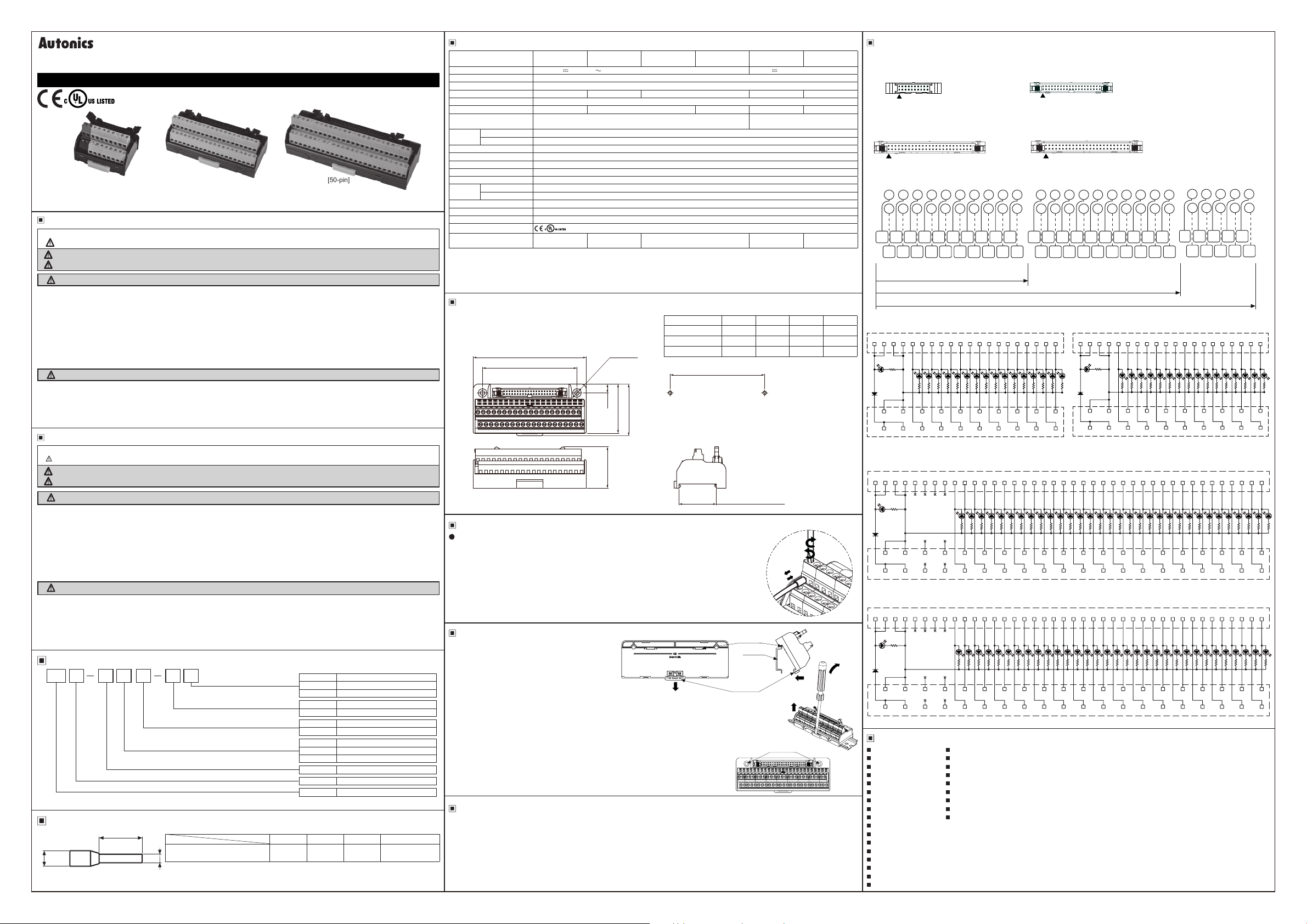
● AFR-H20 / AFR-H40 / AFR-H50(B)
Controller side (connector)
0000000000 0000000000
Terminal block
● AFR-H20-LN ● AFR-H20-LP
Controller side (connector)
1
3 2 4 5 6 7 8 9 10 1511 1612 1713 1814 19 20
V
i-,/
I
8 5
I
46.5
48.8
L--------------------------~
Terminal block
● AFR-H40-LN
39
35mm DIN RAIL
③
①
④
②
DIN rail
connector
D
①
DIN rail
Rail lock
Panel
mounting hole
②
④
Controller side (connector)
r------------------------------------------7
1 3 2 4 5 6 7 8 9 10 1511 1612 1713 1814 19 20
~
L------------------------------------------~
Terminal block
● AFR-H40-LP
Controller side (connector)
r------------------------------------------7
1 38 403937
1
③
L------------------------------------------~
Terminal block
Major Products
~
Photoelectric sensors Temperature controllers
■ ■
Fiber optic sensors Temperature/Humidity transducers
■ ■
Door sensors SSRs/Power controllers
■ ■
Door side sensors Counters
■ ■
Area sensors Timers
■ ■
Proximity sensors Panel meters
■ ■
Pressure sensors Tachometer/Pulse (Rate)meters
■ ■
Rotary encoders Display units
■ ■
Connector/Sockets Sensor controllers
■ ■
Switching mode power supplies
■
Control switches/Lamps/Buzzers
■
I/O Terminal Blocks & Cables
■
Stepper motors/drivers/motion controllers
■
Graphic/Logic panels
■
Field network devices
■
Laser marking system (Fiber, CO₂, Nd:YAG)
■
Laser welding/cutting system
■
«JI-
·················•,rw-nll
._
________
······••&.&.
■■■■■■■■■
eeeeeeeeeeeeeeeeeeN
---------
1
1AeeeeeeeeeeeeeeeeeeE
Connecting Crimp Terminals
Connecting and Removal end sleeve (ferrule terminal) crimp terminal
at rising clamp type terminal block
● Connection
1) Insert a at-head screw driver into the hole above the terminal. Rotate the screw in direction ① (CCW).
2) Push the end sleeve (ferrule) crimp terminal towards direction ②.
3) Insert a at-head screw driver into the hole above the terminal. Rotate the screw in direction ③ (CW).
The tightening torque should be between 0.4 and 0.6N m.
● Removal
1) Insert a at-head screw driver into the hole above the terminal. Rotate the screw in direction ① (CCW).
2)Remove the end sleeve (ferrule crimp terminal) towards direction ④.
1---------------------l
Installation
~
1. Mounting to and removal from DIN rail.
● Mounting
1) Pull the rail lock towards direction ①.
2) Attach the D N rail connection hook onto the DIN rail.
3) Push the unit down to the ② direction and then push up
the rail lock to the unit body.
● Removal
1) Insert a screwdriver into hole of rail lock and pull it towards direction ③.
2) Remove the unit by pulling the unit towards direction ④.
2. Mounting with screws
1) The unit can be mounted on panels using the mounting holes next to the hirose connector.
2) M4×25mm spring washer screws are recommended for installation. When using at washers,
use Ø8mm diameter washers. The tightening torque should be between 0.7 and 1.0N m.
Cautions during Use
~
1. Follow instructions in 'Cautions during Use'. Otherwise, it may cause unexpected accidents.
2. Keep away from high voltage lines or power lines to prevent inductive noise.
In case installing power line and input signal line closely, use line filter or varistor at power line and shielded wire at input signal line.
Do not use near the equipment which generates strong magnetic force or high frequency noise.
3. This unit may be used in the following environments.
2
)
①Indoors (in the environment condition rated in 'Specifications')
②Altitude max. 2,000m
③Pollution degree 2
④Installation category II
● AFR-H40 / AFR-H40-LN(P)
Hirose connector model:
※
2 20
111
J:
===
= = = = =
=t
....
1
2 50
...
1
2 4
1 3 5 7 9 11 13 15 17 19
B2B1 B3 B4 B5 B6 B7 B8 B9
~
A1 A2 A3 A4 A5 A6 A7 A8 A9
24VDC
GND
111
19
49
8 10 12 14 16 18 20
6
I I I I I I I I I I I I I I I I I I I I I I I I
:~:~:~:~:~:~:~:~:
I I I I I I I I I I I I I I I I I I I I I I I I
AFR-H20
00 01 02 03 04 05 06 07
08 09 0A 0B 0C 0D
HIF3BA-40PA-2 54DSA
2
q:::::::::g:::::::::fil
....
1
Hirose connector model:
※
HIF3BB-50PA-2 54DSA
2 50
m.lj:
:::::::::
...
1
22 24 26 28 30 32 34 36 38 40
21 23 25 27 29 31 33 35 37 39
l:~:~:~:~:~:~:~:~:~:
B10
- - 7 r
B12
B11 B13 B14 B15 B16 B17 B18 B19 B20
A10
A11 A12 A13 A14 A15 A16 A17 A18 A19 A20
I
I
I I
I I
I I I
0E 0F
40
39
:::
: : : : : : : : :
:::(ti
49
42
44 46 48 50
41
43 45 47 49
&c:
r~:~:~:
B21 B22 B23 B24 B25
A22 A23
A21
00000
AFR-H40
AFR-H50(B)
Controller side (connector)
1 3 2 4 5 6 7 8 9 10 1511 1612 1713 1814 19 20
--
-
00 01 02 03 04 05 06 07
GND
24VDC
L--------------------------~
Terminal block
08 09 0A 0B 0C 0D
24 332922 26 353121 25 343023 2827 3632
1l1-%
24VDC
3 2 4 5 6 7 8 9 10 1511 1612 1713 1814 19 20 24 332922 26 353121 25 343023 2827 3632
GND
N.C
N.C 00100111021203130414051506160717081809190A1A0B1B0C1C0D
N.C
1l1-%
GND
24VDC
N.C
N.C
00100111021203130414051506160717081809190A1A0B1B0C1C0D
N.C
N.C
A25
A24
0E 0F
38 403937
0E1E0F
1DN.C
1D
1F
0E1E0F
1F
DRW180853AA
I
 Loading...