

Autonics AFR Series Catalog Page

AFR Series
Rising Clamp Interface Terminal Block
---------------
Rising Clamp Interface Terminal Block
Features
New 20-pin models are available on the AFR series (AFR-H20-
●
Rising clamp type connection method offers simple, easy and
●
durable connection
Slim and compact design with 5mm terminal pitch
●
Ideal for connector type PLCs and dedicated controller I/O
●
DIN rail mount and screw mount methods
●
※
Autonics I/O cable CJ Series is recommended.
Refer to I/O cable of I/O terminal block catalogue.
Please read “Safety considerations” in operation
manual before using.
l~&~
____
__.I
C €
®LISTED
Model
Model Item Terminal type Connector type No. of connector pins
AFR-H20
AFR-H20-LN
AFR-H20-LP PNP
AFR-H40
AFR-H40-LN
AFR-H40-LP PNP
AFR-H50
AFR-H50B HIF3BB
Interface
terminal block
Rising clamp
Hirose
connector
20
40
50 None None
Crimp Terminal Specications
End Sleeve (ferrule terminal) crimp terminals
l
10.0 to 12.0
≤2.0
※
Applicable wire: AWG22-16 (0.30 to 1.25mm
l:..------.-1
--------,l
≤4.1
2
)
(unit: mm)
Specications
Model AFR-H20 AFR-H40 AFR-H50 AFR-H50B
Power supply ≤125VDC
Rated current ≤1A
Terminal type Rising Clamp
No. of terminals 20 40 50 16
Terminal pitch 5.0mm
Connector type XG4A-2031 HIF3BA HIF3BB XG4A-2031 HIF3BA
Indicator
Applicable
wire
Stripped wire length 6 to 8mm
Insulation resistance ≥1,000MΩ (at 500VDC megger)
Dielectric strength 600VAC 50/60Hz for 1 minute
Vibration 0.75mm amplitude at frequency of 10 to 55 Hz (for 1 min) in each X, Y, Z direction for 2 hours
Shock 150m/s
Environ
-ment
Material CASE: Polycarbonate, BASE: Polycarbonate
Tightening torque 0.4 to 0.6N·m
Protection structure IP20(IEC standard)
Approval
Weight
※
1: Please connect to a load using the same power supply. Connecting to a load from a different power supply may cause safety issues.
※
2: Among 20 terminals, 16 terminals are available for I/O and 4 terminals are LED power.
※
3: Among 40 terminals, 32 terminals are available for I/O and 8 terminals are LED power and N.C (Not Connect) terminals.
※
4: When using stranded wire, use end sleeve (ferrule terminal) crimp terminals.
※
5: The weight includes packaging. The weight in parenthesis is for unit only.
※
Environment resistance is rated at no freezing or condensation.
Solid wire Ø0.3 to Ø1.2mm
I
Stranded wire
I
Ambient temp. -15 to 55℃, storage: -25 to 65
I
Ambient humi. 35 to 85%RH, storage: 35 to 85%RH
I
※
5
-
※
4
AWG22-16 (0.30 to 1.25mm2)
2
(approx. 15G) in each X, Y, Z direction for 3 times
(E
@usrm
Approx. 98.7g
(approx. 61g)
I
, 125VAC 50/60Hz 24VDC ±10%
---
~
I I
I
Approx. 183g
(approx. 116g)
I
I I I
℃
Approx. 210g (approx. 143g)
I I I
)
□
Connector Indicator (LED) Input logic
XG4A-2031
HIF3BA
None None
LED indicator
None None
LED indicator
AFR-H20-LN
AFR-H20-LP
I I
Power indicator: Red LED
Operation indicator: Blue LED
Approx. 98.8g
(approx. 61.1g)
NPN
NPN
---
※
2
I
Line-up
- e
I
AFR-H40-LN
AFR-H40-LP
※
3
32
Approx. 188g
(approx. 118g)
I/O Termina l Blocks
Inter face
Terminal Block
AFS
(screw)
AFL
(screwless)
AFR
(rising clamp)
Common
Terminal Block
ACS
(screw)
Sensor Connector
Terminal Block
AFE
(
sensor Connector
Relay
Terminal Block
ABS
(screw)
ABL
(screwless)
Power Relay
( relay terminal
block)
I/O Cables
MITSUBISHI
LSIS
Autonics
RS Automation
YOKOGAWA
FUJI
KDT
OMRON
TELEMECANIQUE
For SERVO
Open Type Cab les
Cable Appearance
Remote I /O
ARD
( DeviceN et Digi tal
Standard Terminal Type)
ARD
( DeviceN et Digi tal
Sensor Co nnector Type)
ARD
( DeviceN et Anal og
Standard Terminal Type)
ARM
( Modbus Digital
Sensor Co nnector Type)
Others
Sensor Connectors
Sockets
Sensor Distribution
Boxes
Valve Plugs
Thumbwheel
Switches
)
Autonics
A-13
AFR Series
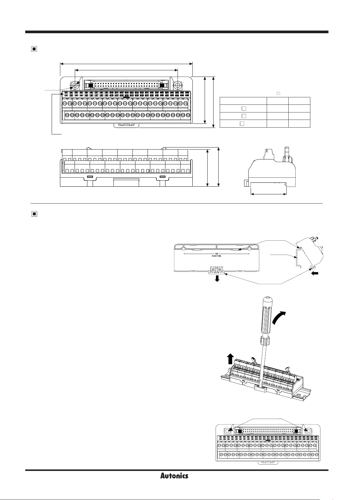
Dimensions
A
B
2-Ø4.5
Power indicator (red) / Operation indicator (blue)
(applied model: AFR-H20-LN(P), AFR-H40-LN(P))
Installation
1. Mounting and Removing from DIN rail
●
Mounting
1)Pull the rail lock towards direction ①.
2)Attach the DIN rail connection part onto the DIN
rail.
3)Push the unit towards direction ②, then push the
rail lock in to lock into position.
DC:::::::-
46.5
37
※
Dimensions are for AFR-H50
Model
50.6
AFR-H20
AFR-H40
AFR-H50
39.1
-
□
-
□
□
①
(unit: mm)
.
□
A B
57.5 53
106.5 89
131.5 102
I I I
35.2
DIN rail
connection part
Rail lock
DIN rail
②
●
Removal
1)Insert a screwdriver into the rail lock hole and pull it towards direction ③.
2)Remove the unit by pulling the unit towards direction ④.
2. Mounting with screws
1)The unit can be mounted on panels using the mounting holes next
to the hirose connector.
2)M4×25mm spring washer screws are recommended for installation.
When using flat washers, use Ø8mm diameter washers. The
tightening torque should be between 0.7 to 1.0N·m
A-14
Autonics
③
④
Mounting holes
 Loading...