

Autonics AFE Series Instruction Manual
DRW170728AB
Autonics
SENSOR CONNECTOR TERMINAL BLOCK
AFE Series
I N S T R U C T I O N M A N U A L
Thank you for choosing our Autonics product.
Please read the following safety considerations before use.
Safety Considerations
Please observe all safety considerations for safe and proper product operation to avoid hazards.
※
symbol represents caution due to special circumstances in which hazards may occur.
※
Failure to follow these instructions may result in serious injury or death.
Warning
Failure to follow these instructions may result in personal injury or product damage.
Caution
Warning
Caution
Sensor
connector
terminal
block
Terminal
Side
Connector
type
Sensor
connector
4-pin
socket
②
Controller side
I
Connector
The number of
type
connector pin
20-pin 16
Hirose
connector
40-pin 32
< Mounting > < Removing >
” and
②
①
The number
of Sensor
connector
DIN rail
Rail lock
Case
LED
type
Full
-
s
Ye
case
①
1. Fail-safe device must be installed when using the unit with machinery that may
cause serious injury or substantial economic loss. (e.g. nuclear power control,
medical equipment, ships, vehicles, railways, aircraft, combustion apparatus,
safety equipment, crime/disaster prevention devices, etc.)
Failure to follow this instruction may result in personal injury, economic loss or fire.
2. Do not use the unit in the place where flammable/explosive/corrosive gas, high
humidity, direct sunlight, radiant heat, vibration, impact, or salinity may be
present.
Failure to follow this instruction may result in explosion or fire.
3. Do not connect, repair, or inspect the unit, or remove connector while
connected to a power source.
Failure to follow this instruction may result in fire or electric shock.
4. Do not disassemble or modify the unit.
Failure to follow this instruction may result in fire or electric shock.
1. Use the unit within the rated specifications.
Failure to follow this instruction may result in fire or product damage.
2. Use dry cloth to clean the unit, and do not use water or organic solvent.
Failure to follow this instruction may result in fire or electric shock.
3. Keep the product away from metal chip, dust, and wire residue which flow into
the unit.
Failure to follow this instruction may result in fire or product damage.
4. Do not use the product when a screw of terminal is loosened.
Failure to follow this instruction may result in fire or product damage.
Ordering Information
Model Item
AFE4-H20-16LF
AFE4-H40-32LF
-
The above specifications are subject to change and some models may be discontinued
※
without notice.
Be sure to follow cautions written in the instruction manual and the technical
※
descriptions (catalog, homepage).
Installation
1. Mounting to and removing from
DIN rail.
● Mounting
1)Push rail lock to the direction “①”.
2)Hook DIN rail connector onto D N rail.
3) Push the unit down to the direction “
push up the rail lock to the unit body.
● Removing
1) Insert a screwdriver into hole of rail lock
and pull the lock out to the direction “①”.
2)Removing the unit by pulling to the direction “②”.
Specications
Model AFE4-H20-16LF AFE4-H40-32LF
Power supply 12-24VDC
Allowable voltage range 90 to 110% of rated voltage
Rated current
※
1
≤1A
The number of connector pin 20-pin 40-pin
The number of sensor
connector
Insulation resistance ≥1,000
16 32
(at 500 VDC megger)
MΩ
Dielectric strength 600VAC 50/60Hz for 1 min
0.75mm amplitude at frequency of 10 to 55Hz (for 1 min) in each
X, Y, Z direction for 1 hour
0.75mm amplitude at frequency of 10 to 55Hz (for 1 min) in each
X, Y, Z direction for 10 min
2
(approx. 15G) in each X, Y, Z direction for 3 times
2
(approx. 10G) in each X, Y, Z direction for 3 times
-15 to 55℃, storage: -25 to 65
℃
35 to 85%RH, storage: 35 to 85%RH
Vibration
Shock
Environment
Mechanical
Malfunction
Mechanical 150m/s
Malfunction 100m/s
Ambient
temperature
Ambient
humidity
Material Case, base: PC
Tightening torque 0.7 to 0 8N m
Approval
※
2
Weight
1: The rated current including LED current of terminal block.
※
2: The weight includes packaging. The weight in parenthesis is for unit only.
※
※
Environment resistance is rated at no freezing or condensation.
Approx. 121g (approx. 69g) Approx. 203g (approx. 119g)
Dimensions
● AFE4-H20-16LF
. -
Indicator
※
707672
•11.
r~:
~
● AFE4-H40-32LF
128.5
※
Indicator
※Power:redLED,operationanddisconnection:blueLED
2. Mounting to panel
1)Push rail lock to the direction "①".
2) Secure rail lock by inserting and tightening screws.
It is recommended to use M4×15 mm
of spring washer screws and to use at
washers which are diameter Ø
The tightening torque should be 0.7 to
1.0 N m.
②
6.
33
l
70
72
♦
33
①
①
Rail lock
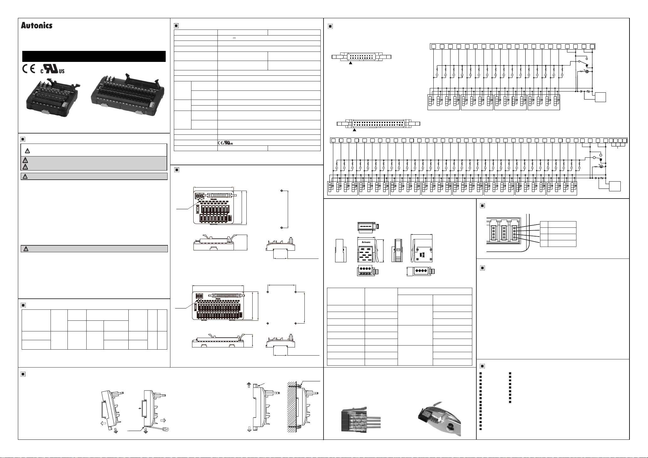
Wire Connections
● AFE4-H20-16LF
Hirose connector model no.
※
2 20
1
● AFE4-H40-32LF
Hirose connector model no.
※
40
2 40
~
·
........
..........
"'
1
34
38
36
(unit: mm)
V
V
V
1
G
1
00
78.8
35mm DIN RAIL
70
78.9
♦----
'
35mm DIN RAIL
2-M4 screw
▣
●
Cover color and wire specications for sensor connector wire mount plug
Model Cover color
CNE-P04-WT Transparent (WT)
CNE-P04-YG Yellow-Green (YG) Ø 0.8 to 1.0
CNE-P04-VT Violet (VT) Ø 1.0 to 1.2
CNE-P04-RE Red (RE)
CNE-P04-YW Yellow (YW) Ø 1.0 to 1.2
CNE-P04-OG Orange (OG) Ø 1.2 to 1.6
CNE-P04-GN Green (GN)
CNE-P04-BL Blue (BL) Ø 1.2 to 1.6
CNE-P04-GY Gray (GY) Ø 1.6 to 2.0
How to Squeeze Sensor Connector Wire Plug
▣
●Check the pin number and insert wires
at the insertion part of the cover.
●Check the wires are inserted at the
end of a cover.
V
2
3
G
G
G
2
3
02
03 040506
01
Specications of Sensor Connector Wire
Mount Plug
Before
squeezing
: HIF3BA-20PA-2.54DSA
19
: HIF3BA-40PA-2.54DSA
.
::
32
30 28 26
V
V
V
5
6
7
G
G
G
5
6
7
12.4
4 3 2 1
-
........
.......
24
V
V
8
9
G
G
8
9
07 08 09
16.1
After
squeezing
20 18 16 14 12 10 8 6 19 17 15 13 11 9 7 5 4 3 2 1
V
V
V
VGV
2
3
G
G
2
3
1210393735
V
V
V
15
16
17
G
G
G
15
16
17
0E 0F1011 12 131415 16
.
39
22
V
10
G
10
~
201816
V
11
G
11
0A 0B
1
G
1
00 01 02 03 04 05
14
V
V
V
14
12
13
G
G
G
14
12
13
0D
0C
(unit: mm)
16.4
5 9
Sensor connector plug is sold separately.
※
Applied wire specications
Norminal cross section
2
)
area (mm
0.05 to 0.08
(AWG30-28)
0.13 to 0.21
(AWG26-24)
0.32 to 0.5
(AWG22-20)
Cover diameter (mm)
Ø 0.6 to 0.8
Ø 0.8 to 1.0
Ø 1.0 to 1.2
2. Squeeze the connector1. Insert wires
● Insert the cover to the body with the tool.
(press tting plier, etc.)
Squeeze it with tools at the side direction
as below gure.
VCC
GND
PNP
NPN
V
V
V
V
V
V
5
6
8
9
7
G
G
G
G
G
5
6
8
9
7
07 08 09 0A 0B
06
31
33
29 27
V
V
V
V
18
19
20
G
G
G
18
19
20
V
V
22
23
21
G
G
G
22
23
21
11
10
G
G
11
10
25
V
24
G
24
17 18 19
V
12
G
12
23
V
V
25
26
G
G
25
26
V
13
G
13
0C
21
1A 1B
V
27
G
27
V
V
15
14
G
G
15
14
0D 0E 0F
17
19
V
V
28
29
G
G
28
29
1C
V
16
G
16
9
11
13
15
GND
V
V
V
31
32
30
G
G
G
31
32
30
1E 1F1D
Sensor Connector Socket Arrangement
1 12-24VDC
2 I/O
3 GND
4 I/O
2 and 4 are connected inside.
※
Cautions during Use
1. Follow instructions in 'Cautions during Use'. Otherwise, it may cause unexpected
accidents.
2. power supply should be insulated and limited voltage/current or Class 2, SELV power
supply device.
3. Check setting of the NPN/PNP selection switch, and use the proper type of product
for the setting.
Failure to follow this instruction may result in shortening the life cycle of the product
or malfunction.
4. Keep away from high voltage lines or power lines to prevent inductive noise.
In case installing power line and input signal line closely, use line filter or varistor at
power line and shielded wire at input signal line.
Do not use near the equipment which generates strong magnetic force or high
frequency noise.
5. This unit may be used in the following environments.
①Indoors (in the environment condition rated in 'Specifications')
②Altitude max. 2,000m
③Pollution degree 2
④Installation category II
Major Products
~
Photoelectric sensors Temperature controllers
■ ■
Fiber optic sensors Temperature/Humidity transducers
■ ■
Door sensors SSR/Power contro lers
■ ■
Door side sensors Counters
■ ■
Area sensors Timers
■ ■
Proximity sensors Panel meters
■ ■
Pressure sensors Tachometer/Pulse (Rate)meters
■ ■
Rotary encoders Display units
■ ■
Connector/Sockets Sensor controllers
■ ■
Switching mode power supplies
■
Control switches/Lamps/Buzzers
■
I/O Terminal Blocks & Cables
■
Stepper motors/drivers/motion controllers
■
Graphic/Logic panels
■
Field network devices
■
Laser marking system (Fiber, CO₂, Nd:YAG)
■
Laser welding/cutting system
■
VCC
GND
1
43
VCC
PNP
NPN
5
2
6
7
N.C.
VCC
GND
DRW170728AB
8
 Loading...