

DRW180231AB
Autonics
COMMON Terminal Block
(screwless type)
ACL Series
I N S T R U C T I O N M A N U A L
(
E:
c@us
Safety Considerations
Please observe all safety considerations for safe and proper product operation to avoid hazards.
※
symbol represents caution due to special circumstances in which hazards may occur.
※
Warning
Caution
Warning
1. Fail-safe device must be installed when using the unit with machinery that may cause serious injury or substantial economic
loss. (e.g. nuclear power control, medical equipment, ships, vehicles, railways, aircraft, combustion apparatus, safety
equipment, crime/disaster prevention devices, etc.)
Failure to follow this instruction may result in fi re, personal injury, or economic loss.
2. Do not connect, repair, or inspect the unit, or remove connector while connected to a power source.
Failure to follow this instruction may result in electric shock or fi re.
3. Do not disassemble or modify the unit.
Failure to follow this instruction may result in electric shock or fi re.
Caution
1. Use the unit within the rated specifi cations.
Failure to follow this instruction may result in fi re or product damage.
2. Use dry cloth to clean the unit, and do not use water or organic solvent.
Failure to follow this instruction may result in electric shock or fi re.
3. Do not use the unit in the place where fl ammable/explosive/corrosive gas, humidity, direct sunlight, radiant heat, vibration,
impact, or salinity may be present.
Failure to follow this instruction may result in fi re or explosion.
4. Keep metal chip, dust, and wire residue from fl owing into the unit.
Failure to follow this instruction may result in fi re or product damage.
Model
Model Item Terminal type The number of terminal Common type
ACL-20L
ACL-20T Top-Bottom Common
ACL-40L
ACL-40T Top-Bottom Common
ACL-50L
ACL-50T Top-Bottom Common
Crimp Terminal Specifi cations
B
Connecting Crimp Terminals
Connecting and removing end sleeve (ferrule terminal) crimp terminal
at screwless type terminal block
Connecting
•
1) Push the end sleeve (ferrule terminal) crimp terminal towards direction ① to complete the connection.
Removing
•
1) Press and hold the catch above the terminal in direction ② with a fl athead screwdriver.
2) Pull and remove the end sleeve (ferrule terminal) crimp terminal towards direction ③.
The above specifications are subject to change and some models may be discontinued without notice.
※
Be sure to follow cautions written in the instruction manual and the technical descriptions (catalog, homepage).
※
LISTED
[20-pin] [40-pin] [50-pin]
Thank you for choosing our Autonics product.
Please read the following safety considerations before use.
Failure to follow these instructions may result in serious injury or death.
Failure to follow these instructions may result in personal injury or product damage.
Left-Right Common
Left-Right Common
Left-Right Common
I I I
A
Common
terminal block
l..-------,--1
Screwless
End Sleeve
C
---------..1
(Ferrule Terminal) crimp
I
~
terminal
Use the UL certifi ed crimp terminal.
※
20
40
50
A B C Applicable wire
10 to 12.0 ≤ 2 0 ≤ 4.1
I
①
③
(unit: mm)
AWG22-16
(0.30 to 1.25mm
(60℃ only)
②
2
Specifi cations
Model ACL-20L ACL-40L ACL-50L ACL-20T ACL-40T ACL-50T
Rated voltage 250VDCᜡ, 250VACᜠ 50/60Hz
Rated current ≤10A
Common type Left +COM / Right -COM Top +COM / Bottom -COM
Terminal type
The number of terminal
Terminal pitch 5 0mm
Applicable
wires
Stripped wire length 8 to 10mm
Insulation resistance ≥1,000MΩ (at 500VDC megger)
Dielectric strength 3,000VAC 50/60Hz for 1 minute (between open terminals)
Vibration
Shock
Environment
Material Terminal: polyamide 66, conductive plate: copper, tin plated, case: polycarbonate, base: polycarbonate
Protection structure IP20 (IEC standard)
Approval
Weight
※
※
Solid wire Ø0.6 to Ø1 25mm (60℃ only)
Stranded wire
Mechanical 0.75mm amplitude at frequency of 10 to 55Hz (for 1 min) in each X, Y, Z direction for 2 hours
Malfunction 0.75mm amplitude at frequency of 10 to 55Hz (for 1 min) in each X, Y, Z direction for 10 minutes
Mechanical 1,000m/s
Malfunction 100m/s
Ambient temp.
Ambient humi.
1
※
1: The weight includes packaging. The weight in parenthesis is for unit only.
Environment resistance is rated at no freezing or condensation.
Screwless
20 40 50 20 40 50
UL: AWG22-16 (0.30 to 1.25mm2) (60℃ only)
-15 to 55℃, storage: -25 to 65
35 to 85%RH, storage: 35 to 85%RH
(€
,®--
Approx. 71g
(approx. 42g)
I
I
2
(approx. 100G) in each X, Y, Z direction for 3 times
2
(approx. 10G) in each X, Y, Z direction for 3 times
Approx. 146g
(approx. 79g)
I
I I I I
I I I I
℃
Approx. 164g
(approx. 97g)
I I I I
I
Approx. 71g
(approx. 42g)
Approx. 146g
(approx. 79g)
Dimensions
ACL-20L(T)
ACL-40L(T) / ACL-50L(T)
•
'I
i
~~~~~~~~~~~~~~~~~~~=
[:;;;][:;;;][:;;;][:;;;:J[:;;;][:;;;][:;;;][ij][ii]
[ I
i;;
Q[
JJ
1nnu
L ':,'. L
""
I~
LI
L L
, ':,'. L
lrlln
Installation
1. Mounting and removal at DIN rail
Mounting
•
1) Pull the rail lock towards direction ①.
2) Attach the DIN rail connection part onto the DIN rail.
3) Push the unit towards direction ②, then push the rail lock in to lock
toward the unit.
)
Removal
•
1) Insert a screwdriver into the rail lock hole and push it towards direction ③.
2) Remove the unit by pulling the unit towards direction ④.
2. Mounting with screws
1)
The unit can be mounted on panel using the mounting hole.
2)
M4×10mm spring washer screws are recommended for installation. When using
fl at washers, use Ø8mm diameter washers. The tightening torque should be from 1.0
to 1.5N m.
A
B
i]IJ
[ii][ij][ij][ii][ij][ij][ii][ij][ii]
[IC
inn
LIL
n
[ [
LL
57.5
53
I
,i;;
M
I L L L
lnlrl
l\r.t--
lie:~
i;;
i:;
inn
L L
46.5
48.8
38
33.1
46.5
38.1
48.8
Model
ACL-40L(T)
ACL-50L(T)
I I
32.9
①
A B
106 5 89
131 5 102
DIN rail connection part
④
Mounting hole
DIN rail
Rail lock
Approx. 164g
(approx. 97g)
(unit: mm)
(unit: mm)
③
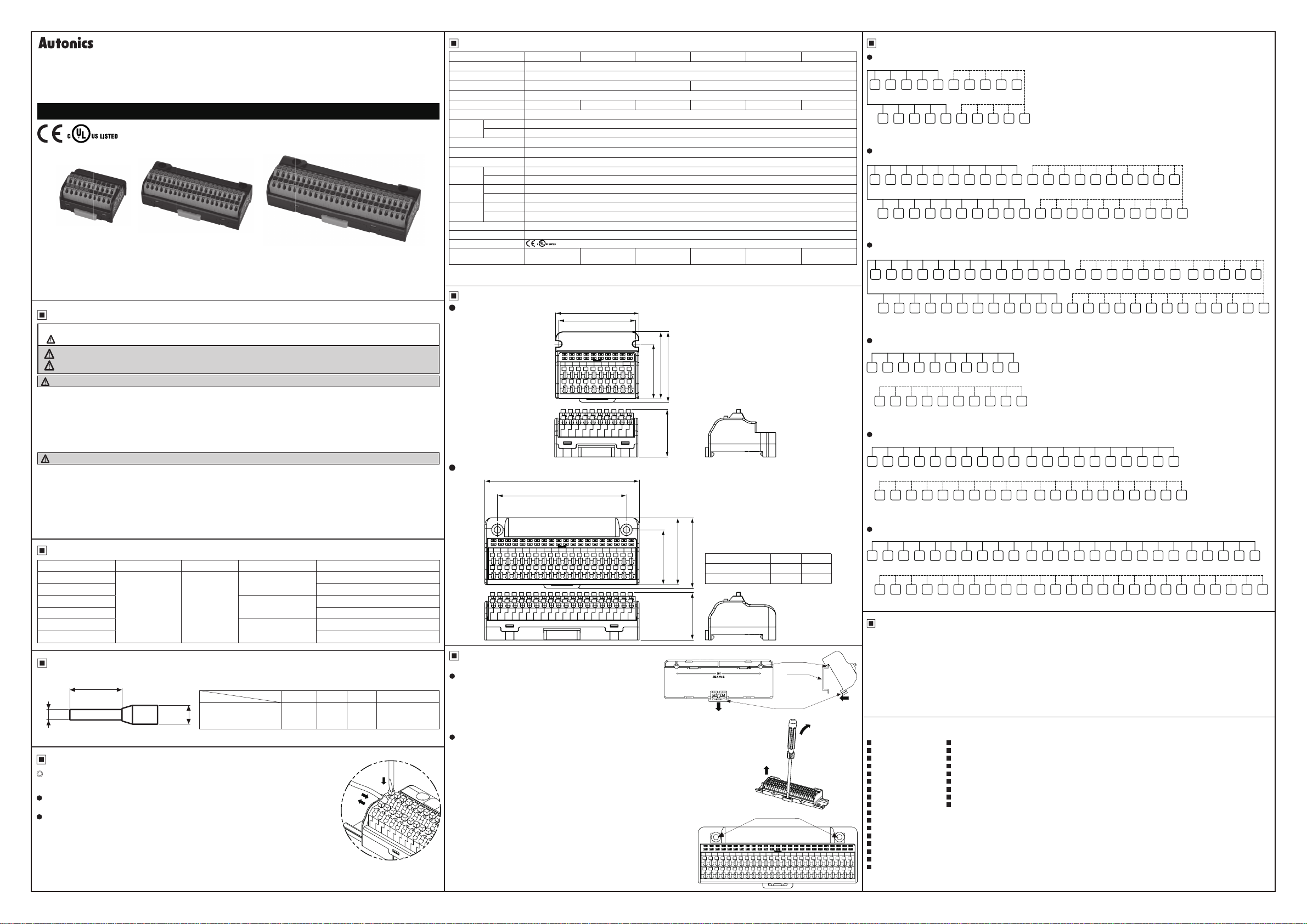
Wire Connections
ACL-20L
-,
B1
B2
B3
B4
B5
B6
B7
B8
B9
000001
-
-
A1
A2
A3
A4
A5
A6
A7
00000
-
-
ACL-40L
•
B1
B2
B3
B4
B5
B6
1c1ic1ic1ic1ic1ic1ic1ic1ic1i2Jooooooooocii
A1
A2
A3
66666666660000000000
ACL-50L
•
B1
B2
A1
ACL-20T
•
B1
B2
A1
A2
0000000000
-
ACL-40T
•
B1
B2
00000000000000000000
A1
A2
00000000000000000006
-
ACL-50T
•
B2
B1
A2
A1
0000000000000000000000000
-
A4
B3
B4
A2
A3
A4
B3
B4
B5
A3
A4
-
-
-
B3
B4
B5
A3
A4
-
-
-
B5
B4
B3
A4
A3
-
-
-
B7
A5
A6
A7
B5
B6
B7
A5
A6
A7
B6
B7
B8
A5
A6
A7
-
-
-
B6
B7
B8
A5
A6
A7
-
-
-
B8
B7
B6
A7
A6
A5
-
-
-
B10
-
-
-
:
:
A8
A9
A10
-
-
-
B15
B16
B17
B18
B19
B8
B9
B10
B11
B12
B13
B14
-
-
-
-
-
-
A8
A9
A10
A11
A12
A13
-
B8
B9
B10
B11
B12
A8
A9
A10
A11
B9
B10
A8
A9
A10
-
-
-
B9
B10
B11
B12
A8
A9
A10
-
B9
A8
-
A11
-
-
-
B12
B11
B10
A11
A10
A9
-
-
-
A14
-
-
-
B13
B14
B15
-
A12
A13
A14
-
-
B13
B14
B15
A12
A13
A14
-
-
-
B15
B14
B13
A14
A13
A12
-
-
-
-
A15
A16
A17
-
-
-
B16
B17
-
-
-
A15
A16
A17
-
-
-
B16
B17
A15
A16
A17
-
-
-
B17
B16
A17
A16
A15
-
-
-
B20
-
-
-
A18
A19
A20
-
-
-
B18
B19
-
A18
-
B18
B19
A18
-
B19
B18
A18
-
B21-B22-B23-B24-B25
B20
-
-
A19
A20
-
-
B20
A19
A20
-
-
B21 B22 B23 B24 B25
B20
A20
A19
-
-
A21-A22-A23-A24-A25
A21-A22-A23-A24-A25
Cautions during Use
1. Follow instructions in 'Cautions during Use'. Otherwise, it may cause unexpected accidents.
2. Keep away from high voltage lines or power lines to prevent inductive noise.
In case installing power line and input signal line closely, use line filter or varistor at power line and shielded wire at input signal line.
Do not use near the equipment which generates strong magnetic force or high frequency noise.
3. This unit may be used in the following environments.
①Indoors (in the environment condition rated in 'Specifications')
②Altitude max. 2,000m
③Pollution degree 2
②
④Installation category II
Major Products
▣
Photoelectric Sensors Temperature Controllers
Fiber Optic Sensors Temperature/Humidity Transducers
Door Sensors SSRs/Power Controllers
Door Side Sensors Counters
Area Sensors Timers
Proximity Sensors Panel Meters
Pressure Sensors Tachometer/Pulse(Rate)Meters
Rotary Encoders Display Units
Connector/Sockets Sensor Controllers
Switching Mode Power Supplies
Control Switches/Lamps/Buzzers
/O Terminal Blocks & Cables
Stepper Motors/Drivers/Motion Controllers
Graphic/Logic Panels
Field Network Devices
Laser Marking System (Fiber, Co₂, Nd:YAG)
Laser Welding/Cutting System
■
■
■
■
■
■
■
■
■
-
-
-
DRW180231AB
 Loading...