


ST7000 Installation
Autohelm®
Contents |
|
|
|
|
|
1. |
System Description |
2 |
4. |
Calibration |
34 |
1.1.1 |
Course Computer |
3 |
4.1 |
Recommended Settings |
34 |
1.1.2 |
Control Unit |
3 |
4.2 |
Calibration Mode |
34 |
1.1.3 |
Fluxgate Compass |
3 |
4.3 |
Adjusting Calibration |
35 |
1.1.4 |
Rudder Reference Transducer |
4 |
4.4 |
Display Contrast Adjustment |
37 |
1.1.5 |
Auxiliary Alarm |
4 |
4.5 |
Permanent Watch Alarm |
38 |
1.1.6 |
Masthead Transducer |
4 |
4.6 |
Recorded Calibration Settings |
38 |
1.1.7 |
Type CR Interface Unit |
5 |
4.7 |
Rudder and Rate Gain Tables |
38 |
1.2 |
Drive Systems |
6 |
5. |
Initial Sea Trials |
|
1.2.1 |
Rotary Drive |
6 |
39 |
||
1.2.2 |
Linear Drive |
7 |
5.1 |
Automatic Deviation Correction |
39 |
1.2.3 |
Hydraulic Drive |
8 |
5.2 |
First Sea Trials |
39 |
1.2.4 |
Constant Running Power Pack |
9 |
5.3 |
Response Control |
39 |
1.2.5 |
Sterndrive |
11 |
5.4 |
Automatic Trim Control |
40 |
2. |
Installation |
|
5.5 |
Rudder Gain Adjustment |
|
12 |
|
(Displacement craft) |
40 |
||
2.1.1 |
Course Computer |
12 |
5.6 |
Rudder Gain adjustment |
|
2.1.2 |
Control Unit |
13 |
|
(High Speed Planing Craft) |
41 |
2.1.3 |
Fluxgate Compass |
13 |
5.7 |
Manual overide |
|
2.1.4 |
Rudder Reference Transducer |
14 |
|
(Sterndrive Actuators only) |
41 |
2.1.5 |
Auxiliary Alarm |
15 |
5.8 |
Rate Gain Adjustment |
41 |
2.1.6 |
Masthead Transducer |
16 |
5.9 |
Compass Alignment |
42 |
2.2 |
Drive Systems |
16 |
6. |
Track Control |
|
2.2.1 |
Rotary Drive |
16 |
43 |
||
2.2.2 |
Linear Drive |
18 |
6.1 |
Functional Test |
43 |
2.2.3 |
Hydraulic Drive |
19 |
6.2 |
Operating Hints |
43 |
2.2.4 |
Stern Drive |
22 |
7. |
Windvane Control (Sail Only) |
|
2.3 |
Cabling and Power Supplies |
26 |
45 |
||
2.3.1 |
Signal Cabling |
26 |
|
|
|
2.3.2 |
Connection to other SeaTalk Units |
27 |
|
|
|
2.3.3 |
NMEA Input |
28 |
|
|
|
2.3.4 |
D.C. Power Supplies and Drive Unit |
28 |
|
|
|
2.3.5 |
Type CR Installations |
30 |
|
|
|
2.3.6 |
Stern Drive Actuator |
31 |
|
|
|
3. |
Functional Test |
32 |
|
|
|
3.1 |
Switch On |
32 |
|
|
|
3.2 |
Rudder Angle Sense |
32 |
|
|
|
3.3 |
Mechanical Test (Manual Steering) |
32 |
|
|
|
3.4 |
Rudder Angle Alignment |
32 |
|
|
|
3.5 |
Operating Sense |
32 |
|
|
|
3.6 |
Rudder Deadband |
32 |
|
|
|
3.7 |
Mechanical Test (Autopilot Steering) |
32 |
|
|
|
3.8 |
Mechanical Test – Sterndrive |
33 |
|
|
|
|
(Autopilot steering) |
|
|
|
|
3.9 |
Rudder Angle Limit |
33 |
|
|
|
1

1. System Description
The ST7000 is a modular automatic pilot system that can be built up to match the individual requirements of all types of vessels. A range of high efficiency rotary, linear, and hydraulic rudder drive units are available to match all types of steering systems.
The ST7000 is SeaTalk compatible providing full data sharing with Autohelm range of SeaTalk instruments.
2
The control unit has a built in interface which will accept navigation and wind angle data to 0180/0183 format.
A fully comprehensive installation is shown below. The most basic installation would consist only of a central course computer, drive unit, fluxgate compass, rudder reference unit and a single control unit.

1.1.1 Course Computer
(Cat. No. Z083-12V Cat. No. Z084-24V)
The course computer houses the microprocessor, electronic control circuitry and power amplifier for the drive unit. The course computer is splash proof only and must be mounted in a dry and protected position. The course computer is available for operation with 12V and 24V power supply.
1.1.2 Control Unit (Cat. No. Z082)
The control unit is designed for above or below deck mounting. The control unit accepts NMEA 0183 navigation and wind angle data input.
1.1.3 Fluxgate Compass (Cat. No. Z130)
The fluxgate compass has been especially developed for marine application. The compass contains a gimbal mechanism to permit accurate readings with pitch and roll movements up to +35 deg. The compass is bulkhead mounted below decks and connects directly to the course computer.
The fluxgate compass may be mounted above deck on steel vessels however autopilot performance may be degraded due to the increased motion.
3

1.1.4 Rudder Reference Transducer
(Cat. No. Z131)
The rudder reference transducer provides the course computer with a precise rudder position. It is mounted on a suitable base adjacent to the rudder stock. The interconnecting cable connects directly to the course computer connector unit.
1.1.5 Auxiliary Alarm (Cat. No. Z035)
The autopilot is provided with an automatic off course alarm system which sounds from all control units and provides sufficient audible warning under most conditions. In cases where a high power alarm is necessary, an auxiliary alarm can be fitted. The auxiliary alarm is connected to the main connector unit via a two core cable.
1.1.6 Masthead Transducer (Sail Only)
(Cat. No. Z080)
If the installation does not include an Autohelm ST50 Wind Instrument the masthead transducer can be connected directly to the course computer to supply wind angle information.
4

1.1.7 Type CR Interface Unit
(Cat. No. Z085)
A standard ST7000 course computer can be connected to the solenoids on a constant running hydraulic power pack using the Type CR Interface Unit. The unit also provides connections to energise a solenoid operated bypass valve if required.
5

1.2 Drive Systems
The ST7000 offers a choice of Mechanical or Hydraulic Drive Units. All vessels with hydraulic steering will require a hydraulic drive unit (see section 1.2.3).
Mechanical steering systems may be driven with either a rotary or linear drive unit. If space permits the linear drive unit provides the simplest installation by connecting directly to the rudder stock tiller arm. It may also be used to power steer the vessel if steering linkage failure occurs.
1.2.1 Rotary Drive Units
The Autohelm Rotary Drive Units provide smooth powerful steering commands with virtually silent operation.
A rugged electric motor drives a precision epicyclic gearbox via a high tensile belt drive. An electronic clutch is totally fail-safe yet transmits high torque loads with no slippage.
The drive units can be mounted in any attitude simplifying installation.
6
1.2.2 Linear Drive Units
The Autohelm Linear Drive Units are of outstanding design which features powerful thrust, fast hard overtimes and near silent operation. When backdriven the movement is smooth with minimal backdrive force. Using a high tensile belt
drive and epicyclic reduction gearbox the powerful electric motor is controlled by an electronic failsafe clutch.
The design is highly efficient and provides high performance for minimum current consumption.
A tiller arm of adequate strength must be used to transfer drive from the drive unit to the rudder shaft. Both Edson and Whitlock Marine provide suitable standard tillers.
|
|
|
Type 1 |
Type 2S |
Type 2L |
Supply Voltage |
|
12 volts |
12 volts(24V optional) |
12 volts(24V optional) |
|
Peak Thrust |
|
295Kg(650lb) |
480Kg(1050lb) |
480Kg(1050lb) |
|
Maximum Stroke Speed |
28mm/sec(1.1 |
28mm/sec(1.1 in/sec) |
28mm/sec(1.1 in/sec |
||
|
|
|
in/sec) |
|
|
Maximum Stroke |
|
300mm(12in) |
300mm(12in) |
400mm(16in) |
|
Overall |
length at |
Mid |
700mm(27.5in) |
700mm(27.5in) |
850mm(33.5in) |
Stroke 'A' |
|
|
|
|
|
Tiller |
Arm Length |
'B' |
250mm(10in) |
250mm(10in) |
350mm(14in) |
(+35deg Rudder) |
|
|
|
|
|
Maximum Rudder Torque |
735Nm(6500lb in) |
1190Nm(10,500lb in) |
1660Nm(14,700lb in) |
||
Power |
Consumption |
1.5 - 3 amps |
2.75 - 6 amps |
2.75 - 6 amps |
|
(typical average) |
|
|
|
|
|
Suitable for vessels up to |
14m(45ft) LOA |
17m(55ft)LOA |
18m(60ft)LOA |
||
Maximum displacement |
11800Kg(26000lbs) |
20000Kg(44000lbs) |
25000Kg(55000lbs) |
||
1.2.3 Hydraulic Drive Units
Two reversing hydraulic drive units are available depending on the size of the vessel and the displacement of the ram.
The vessel size and displacement recommendations given below apply to directly driven steering systems. When a power steering system is fitted the vessel size and displacement recommendations can be ignored.
Type 1 and Type 2
The hydraulic drive unit consists of a precision gear pump with integral check valve block driven by a continuously rated servo motor. The pump drive motor is connected directly to the course computer which also regulates peak pump pressure.
|
Type 1 |
Supply Voltage |
12 volts |
Regulated Peak Pressure |
50 bar (750 psi) |
Flow Control Integral |
Pilot Check Valve Integral |
Peak Flow Rate (unloaded) |
I 1 00cc/min (67in3/min) |
Minimum Ram Capacity |
100cc (6in3) |
Maximum Ram Capacity |
230cc (14in3) |
Ram Type |
Single or Double Ended |
Power Consumption (typical |
2 - 4 amps |
average) |
|
Overall Length 'A' |
190mm (7.5in) |
Maximum Vessel size |
13m (42ft) |
Maximum Vessel Displacement |
118OOKg (26000lbs) |
7
Type 2
12 volts (24V optional)
55 bar (900 psi)
Pilot Check Valve Integral 1700cc/min (103in3/min) 200cc (12in3)
400cc (24in3)
Single or Double Ended 4 - 8 amps
216mm (8.5in) 18m (60ft)
24OOOKg (55000lbs)
8
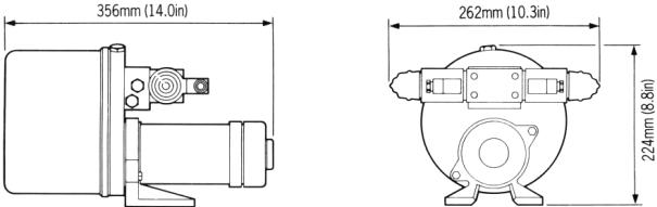
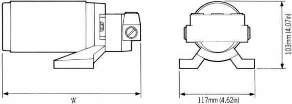
1.2.4 Constant Running Power Pack
When steering loads require a ram capacity above 400cc (24in3) the Autohelm Constant Running Power pack provides the ideal autopilot drive system.
Hydraulic fluid is provided from a self contained reservoir and flow to the steering ram is controlled by integral solenoid operated valves.
For the most rugged and demanding steering applications the Autohelm Constant Running Power pack is the optimum solution.
Used with a solenoid operated bypass valve and separate hydraulic ram this system is recommended for heavy duty applications on large mechanically steered vessels.
|
Type CR1 |
Type CR2 |
Supply Voltage |
12 volts (24V optional) |
12 volts (24V optional) |
Regulated Peak Pressure |
50 bar (750 psi) |
50 bar (750 psi) |
Peak Flow Rate (unloaded) |
3000cc/min (180in3/min) |
4500cc/min (270in3/min) |
Minimum Ram Capacity |
400cc (24in3) |
750cc (46in3) |
Maximum Ram Capacity |
750cc (46in3) |
1500cc (92in3) |
Ram Type |
Single or Double Ended |
Single or Double Ended |
9

Power Pack Selection (Constant Running) Hydraulic power pack selection depends on the vessels overall length and the displacement of the steering cylinder.
Using figure 2 establish the target hardover time for your vessel. This is combined with the steering cylinder displacement in figure 3 to select the appropriate hydraulic power pack.
10
Note: If power packs other than the Autohelm models are used with the ST7000 the following solenoid specifications must comply-
Pull in Voltage - less than 8V (16v for 24v systems)
Drop out Voltage - greater than 2V Operating Current - less than 5A
The Solenoid Voltage must be the same as the course computer.

1.2.5 Sterndrive
The Sterndrive Actuator must only be used on sterndrives with cable operated power assisted steering.
The drive unit operates the power steering valve identically to the steering cable. A clutch disengages the drive unit to allow manual steering when the autopilot is disengaged.
Two installation kits are available to allow connection to different engine manufacturers equipment.
Cat. No. |
Manufacturer |
D129 |
Volvo Penta |
D137 |
Mercruiser/OMC/Yamaha |
Specifications |
|
Description |
Size |
Hardover/Hardover |
8.8 secs |
time (unloaded) |
|
Stroke |
190mm(7.5in) |
Power |
1.5 - 3 amps |
Consumption(Typical |
|
average) |
|
Maximum Thrust |
150 Kgf (330lbs) |
11

2. Installation
2.1.1 Course Computer
Mounting Position - Below Deck
The course computer should be positioned in a dry protected area of the vessel free from high operating temperatures and excessive vibration. It can be mounted in any attitude. Care must be taken to allow at least 150mm (6in) clearance all round to aid heat dissipation from the power amplifier in the unit. Do not mount in the engine room.
Do not position the course computer so that it will:
•Receive any direct water splash/spray (from Bilge/Hatch etc).
•Be liable to physical damage from heavy items.
•Be covered by other equipment or onboard gear.
•Be close to major sources of transmitted energy (Generators/SSB radios, Aerial Cables etc).
12
Mounting Instructions
•Remove Terminal box lid (Fig. 4).
•Unscrew two internal thumb retaining nuts (Fig. 4).
•Unplug terminal box and mounting spine.
•Position terminal box and mounting spine in correct location, mark off and pilot drill for the 5 self-tapping screws supplied (Fig. 5).
•Screw terminal box and mounting spine into place.
•Plug course computer unit to terminal box. Retighten thumb retaining screws.
The course computer is now ready for wiring (see 2.3).
 Loading...