


Distributed by
Any reference to Raytheon or RTN in this manual should be interpreted as Raymarine. The names Raytheon and RTN are owned by the
Raytheon Company.

TYPE
100/300
AUTOPILOT
Installation and Set Up
Contents |
3 |
|
|
|
|
Contents
Chapter 1: Introduction .......................................................................... |
9 |
1.1 ST7000 Control Unit ................................................................. |
10 |
1.2 ST6000 Control Unit ................................................................. |
10 |
1.3CourseComputer ..................................................................... |
11 |
1.4FluxgateCompass .................................................................... |
11 |
1.5RotaryRudderReferenceTransducer .......................................... |
12 |
1.6LinearFeedbackTransducer ...................................................... |
12 |
1.7TypeCRInterfaceUnit ............................................................... |
12 |
1.8DriveSystems .......................................................................... |
13 |
RotaryDriveUnits ..................................................................... |
13 |
ReversingHydraulicPump ......................................................... |
14 |
LinearDrive ............................................................................. |
15 |
HydraulicLinear ....................................................................... |
15 |
ConstantRunningHydraulicPump .............................................. |
16 |
Sterndrive ............................................................................... |
16 |
1.9Options ................................................................................... |
17 |
Hand-heldRemote(Z101) .......................................................... |
17 |
NMEAInterface(D153) .............................................................. |
17 |
AuxiliaryAlarm(Z035) ............................................................... |
18 |
Joystick(Z147) ........................................................................ |
18 |
WindTransducer(sailonly) ......................................................... |
19 |
MastheadWindTransducer(Z080,LongArmVersionZ188) ...... |
19 |
PushpitWindTransducer(Z087) ............................................ |
19 |
GyroplusTransducer(Z179) ...................................................... |
20 |
Chapter 2: Installation .......................................................................... |
2 1 |
2. General .................................................................................... |
21 |
PlanningtheInstallation ............................................................. |
21 |

4 |
TYPE100/300 Operation and Installation Handbook |
|
|
2.1CourseComputer ..................................................................... |
21 |
|
Mounting ................................................................................. |
22 |
|
Cabling ................................................................................... |
22 |
|
Type1DriveUnits/SternDrive/ConstantRunningPump ............ |
23 |
|
Type2DriveUnits(12V) ........................................................ |
23 |
|
Type2DriveUnits(24V) ........................................................ |
23 |
|
Type3DriveUnits(12V) ........................................................ |
24 |
|
Type3DriveUnits(24V) ........................................................ |
24 |
|
2.2 ST7000/6000 Control Unit ........................................................ |
25 |
|
Mounting ................................................................................. |
25 |
|
Cabling ................................................................................... |
26 |
|
2.3FluxgateCompass .................................................................... |
28 |
|
Mounting ................................................................................. |
28 |
|
Cabling ................................................................................... |
29 |
|
2.4RotaryRudderReferenceTransducer .......................................... |
30 |
|
Mounting ................................................................................. |
30 |
|
Cabling ................................................................................... |
32 |
|
2.5LinearFeedbackTransducer ...................................................... |
33 |
|
Mounting ................................................................................. |
33 |
|
Cabling ................................................................................... |
34 |
|
2.6HydraulicDriveSystems ............................................................ |
35 |
|
PumptoCylinderSpecifications .................................................. |
35 |
|
ReversingHydraulicPumps(Type1,Type2&Type3) ................... |
35 |
|
Mounting ............................................................................ |
35 |
|
Cabling ............................................................................... |
35 |
|
Type1DriveUnit ........................................................... |
35 |
|
Type2DriveUnit(12V) ................................................... |
36 |
|
Type2DriveUnit(24V) ................................................... |
36 |
|
Type3DriveUnit(12V) ................................................... |
36 |
|
Type3DriveUnit(24V) ................................................... |
36 |

Contents |
5 |
Plumbing ............................................................................ |
37 |
Twolinesystem ................................................................... |
39 |
Twolinepressurisedsystem .................................................. |
39 |
Threelinesystem ................................................................. |
40 |
Bleedingthesystem ............................................................. |
40 |
ConstantRunningHydraulicPump .............................................. |
41 |
Mounting ............................................................................ |
41 |
Cabling ............................................................................... |
42 |
PumpCable ................................................................. |
43 |
SolenoidCable ............................................................. |
43 |
Plumbing ............................................................................ |
44 |
HydraulicLinearActuator ........................................................... |
45 |
Installation .......................................................................... |
45 |
Cabling ............................................................................... |
48 |
FinalPreparationsBeforeuse ................................................ |
48 |
2.8MechanicalDriveSystems ......................................................... |
49 |
RotaryDriveUnit ...................................................................... |
49 |
Mounting ................................................................................. |
49 |
Cabling ................................................................................... |
52 |
Type1DriveUnit .................................................................. |
52 |
Type2DriveUnit(12V) ......................................................... |
52 |
Type2DriveUnit(24V) ......................................................... |
53 |
LinearDriveUnit ....................................................................... |
53 |
Mounting ................................................................................. |
54 |
Cabling ................................................................................... |
55 |
Type1DriveUnit .................................................................. |
55 |
Type2DriveUnit(12V) ......................................................... |
55 |
Type2DriveUnit(24V) ......................................................... |
56 |
SterndriveActuator .................................................................. |
56 |
Mounting ................................................................................. |
56 |

6 |
TYPE100/300 Operation and Installation Handbook |
|
|
Volvo(Pretype872215) ....................................................... |
56 |
|
Volvo(Posttype872215) ..................................................... |
58 |
|
Mercruiser/OMC/Yamaha ..................................................... |
61 |
|
MountinginaRestrictedArea ................................................. |
63 |
|
Cabling ................................................................................... |
64 |
|
2.9AuxiliaryAlarm ......................................................................... |
65 |
|
Cabling ................................................................................... |
65 |
|
2.10 Joystick ................................................................................ |
66 |
|
Cabling ................................................................................... |
66 |
|
2.11MastheadTransducer(sailonly) ................................................ |
67 |
|
Mounting ................................................................................. |
67 |
|
Cabling ................................................................................... |
68 |
|
2.12Interfacingtoothermanufacturer'sequipment(NMEA) ................. |
69 |
|
CourseComputerNMEAports ................................................... |
69 |
|
InputPort ............................................................................ |
69 |
|
OutputPort ......................................................................... |
70 |
|
Cabling ............................................................................... |
70 |
|
ST6000/ST7000ControlUnitNMEAInput ................................... |
71 |
|
Cabling ............................................................................... |
72 |
|
NMEAInterface ........................................................................ |
73 |
|
Cabling ............................................................................... |
74 |
|
Chapter 3: Functional Test ................................................................... |
7 6 |
|
3.1 System test ............................................................................. |
76 |
|
3.2Switch-on ................................................................................ |
76 |
|
3.3Rudderanglesense .................................................................. |
77 |
|
ST7000 control unit .................................................................. |
77 |
|
ST6000 control unit .................................................................. |
77 |
|
3.4Rudderanglealignment ............................................................. |
77 |
|
3.5Operatingsense ....................................................................... |
78 |
|
3.6Rudderdeadband ..................................................................... |
78 |

Contents |
7 |
3.7Mechanicaltest(Linear,Rotary&HydraulicDrives) ........................ |
78 |
Currentlimitandcutout ............................................................. |
78 |
3.8MechanicalTest(SternDrive) ..................................................... |
79 |
3.9SettingtheAutopilotRudderLimit(Alldrives) ................................. |
79 |
3.10GyroPlusOffsetandDriftCompensation .................................... |
80 |
Procedure ............................................................................... |
80 |
Chapter 4: Calibration .......................................................................... |
8 1 |
4.1RecommendedSettings ............................................................ |
81 |
4.2Selectingcalibration .................................................................. |
82 |
4.3Adjustingcalibration .................................................................. |
83 |
RudderGain ............................................................................. |
83 |
RateLevel ............................................................................... |
84 |
RudderOffset(HelmAdjust) ....................................................... |
84 |
RudderLimit ............................................................................ |
84 |
TurnRate ................................................................................ |
85 |
CruiseSpeed ........................................................................... |
85 |
OffCourseLimit ....................................................................... |
85 |
TrimLevel ............................................................................... |
86 |
JoystickMode(ManualType) ...................................................... |
86 |
DriveOption ............................................................................. |
86 |
RudderDeadband(RudderDamping) .......................................... |
87 |
MagneticVariation .................................................................... |
87 |
AutoAdapt .............................................................................. |
87 |
Latitude .................................................................................. |
88 |
WindTrim ................................................................................ |
88 |
ResponseLevel ........................................................................ |
88 |
AutoRelease(manualoverride) ................................................... |
89 |
4.4SavingCalibrationMode ............................................................ |
89 |
4.5DisplayContrastAdjustment(ST7000only) .................................. |
90 |
4.6PermanentWatchAlarm(SFIA) ................................................... |
90 |
4.7RecordingCalibrationSettings .................................................... |
90 |

8 |
TYPE100/300 Operation and Installation Handbook |
|
|
Chapter 5: Initial Sea Trials ................................................................... |
9 1 |
|
5.1InitialSeaTrials ........................................................................ |
91 |
|
5.2AutomaticCompassHeadingAlignmentandDeviationCorrection ... 91 |
|
|
5.3CompassAlignment(withoutdeviationcorrection) ......................... |
93 |
|
5.4FirstSeaTrials ......................................................................... |
93 |
|
5.5ResponseControl ..................................................................... |
94 |
|
Level1-AutomaticSeaStateControl .......................................... |
94 |
|
Level2-AutomaticSeaStateInhibit ............................................ |
94 |
|
Level3 -AutomaticSeaStateInhibitandcounterrudder ................ |
94 |
|
5.6AutomaticTrimControl ............................................................. |
95 |
|
5.7RudderGainAdjustment(DisplacementCraft) ............................... |
96 |
|
5.8RudderGainAdjustment(HighSpeedPlanningCraft) ..................... |
97 |
|
5.9RudderGain-AdjustmentwithSpeed ........................................... |
97 |
|
5.10ManualOverride (SternDriveActuatorsonly) .............................. |
98 |
|
Chapter 6: Track Control ...................................................................... |
9 9 |
|
Chapter 7: Windvane Control (Sail Only) ............................................. |
101 |
|
Index .................................................................................................. |
103 |
Chapter 1: System Components |
9 |
|
|
|
|
Chapter 1: Introduction
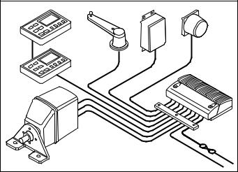
TheAutohelmType100/300autopilotsaremodularsystemsthatcanbe configured tosuittheindividualrequirementsofalltypesofvessels,using arangeofhighefficiencyrotary,linearorhydraulicrudderdriveunitsto matchvarioustypesofsteeringsystems.
The Autohelm system in its most basic form consists of a control unit, coursecomputer,driveunit,fluxgatecompassandarudder referencetransducer.
Afullrangeofaccessoriesarealsoavailableandinclude:
•Joystick(manualsteeringunit)
•Main alarm and interface
•Rate gyro
•Hand held remote control unit
•SeaTalkinstrumentation
•Interface leads
Control |
|
|
Unit |
Rudder |
|
|
|
|
|
Reference |
Fluxgate |
|
Unit |
|
|
Compass |
|
Control |
Gyro |
|
|
|
|
Unit |
|
Course |
|
|
|
|
|
Computer |
|
|
Cable |
|
Drive Unit |
Clamp |
|
|
|
|
|
D726-1 |
10 |
TYPE 100/300 Operation and Installation Handbook |
|
|
|
|
1.1 ST7000 Control Unit
TheST7000controlunitisfullyweatherprotectedanddesignedforabove orbelowdeckistallation.Theunitisconnected tothecoursecomputervia theSeaTalkbus.NMEAnavigation,speedandwindinformationcanbe received via a fixed socket on the rear of the case.
Note: AdditionalcontrolunitscanalsobeconnectedviatheSeaTalkbus.
|
|
177.8mm (7in) |
38.75mm (1.5in) |
||
|
|
|
|
|
24mm (0.95in) |
● |
–1 |
+1 |
● |
|
|
● |
–10 |
+10 |
● |
|
110mm |
|
|
|
|
|
|
|
|
|
|
|
(4.33in) |
STAND BY |
AUTO |
DISPLAY |
TRACK |
RESPONSE |
|
|
|
|
|
|
ST7000 |
|
|
|
|
|
D727-1 |
1.2 ST6000 Control Unit
The ST6000 control unit, like the ST7000, is fully weather protected and alsodesignedforaboveorbelowdeckinstallation.Theunitisconnected tothecoursecomputerviatheSeaTalkbus.NMEAnavigation,speedand windinformationcanbereceivedviaafixedsocketontherearofthecase.
Note: AdditionalcontrolunitscanalsobeconnectedviatheSeaTalkbus.
110mm (4.33in) |
38.75mm (1.5in) |
|||
|
|
|
24mm(0.95in) |
|
–1 |
+1 |
DISPLAY |
|
|
–10 |
+10 |
TRACK |
110mm |
|
(4.33in) |
||||
|
|
|
||
STAND BY |
AUTO |
RESPONSE |
|
|
|
|
ST6000 |
|
|
|
|
|
D728 -1 |
|

Chapter 1: System Components |
11 |
|
|
|
|
1.3 Course Computer
Thecoursecomputer,availableinboth12Vor24Vversions,housesa microprocessor, drive unit electronic control circuitry and power amplifier. It is the central distribution point for the autopilot, electrical wiring and ship’spowerconnectionpoint.
ThecoursecomputeralsohasNMEAinputandoutputstoallowoperation withothermanufacturer'sequipment.
Theunitisonlysplashproofandmust,therefore,beinstalledinadry, protected location.
Type100isusedforType1andTypeCR12Vdrives.Type300isused withType2andType3drives.
233mm (9.2in) |
45mm (1.8in) |
|
130mm (5.1in) |
|
D865-1 |
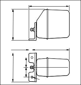
1.4 Fluxgate Compass
Thefluxgatecompasscontainsagimbalmechanismthatpermits accurate readings with pitch and roll movements up to +/- 35 degrees. Thecompassisdesignedforbelowdeck,bulkheadmountingand connects directly to the course computer.
Onsteeldeckedvesselsthecompasscanbemountedabovedeck, however,autopilotperformancemaybeaffectedduetotheincreased motion.
76mm (3in)
TM
76mm (3in)
D729-1

12 |
TYPE 100/300 Operation and Installation Handbook |
|
|
|
|
1.5 Rotary Rudder Reference Transducer
Therudderreferencetransducerprovidesthecoursecomputerwiththe precisepositionofthevesselsrudder.Theunitismountedonasuitable baseadjacenttotherudderstock.Itsuseismandatoryonallinstallations, exceptwhenalinearrudderreferencetransducerisconnected.
152mm (6in) |
139.7mm (5.5in) |
61mm (2.4in) |
69.5mm (2.7in) |
D730-1 |
1.6 Linear Feedback Transducer
Thelinearfeedbacktransducerisdesignedforinstallationson‘bullhorn’ stylehydraulicoutboardsteeringsystems.Theunitistotallyweatherproof andmountedonthebullhornram.Itsuseismandatoryonallhydraulic outboardinstallations.
425mm (16.75in) |
|
TM |
(1.3in) |
|
32mm |
|
D869-1 |
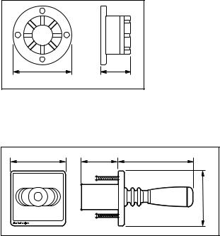
1.7 Type CR Interface Unit
Thecoursecomputercanbeconnectedtothesolenoidsonaconstant runninghydraulicpumpusingthetypeCRinterface.Theunitalsoprovides connectionstoenergiseasolenoidoperatedbypassvalve.
125mm (5.9in) |
|
|
100mm (3.95in) |
60mm |
(2.37in) |
|
D734-1 |
|
Chapter 1: System Components |
13 |
|
|
|
|
1.8 Drive Systems
Arangeofmechanical(rotary,linearandsterndrive)andhydraulicdrive units are available for use with the Type 100/300 system. Rotary drives arecoupledtothesteeringsystembyasimplechaindrive,lineardrives directly to the rudder stock at the tiller arm radius and stern drives directly tothepowersteeringvalveblock.
Thetypeofhydraulicdriveusedisdependentonthesizeofthevessels hydrauliccylinder.
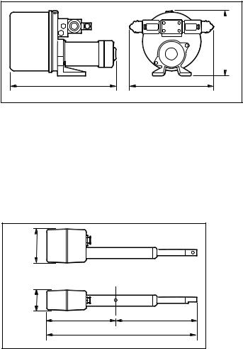
Rotary Drive Units
Autohelmrotarydriveunitsprovidesmooth,powerfulsteeringcommands withalmostsilentoperation.Aruggedelectricmotordrivesaprecision epicyclicgearboxviaahightensiledrivebelt.Anelectronicclutch transmitshightorqueloadswithnoslippage.Thedriveunitcanbe mountedinanyattitudetosimplifyinstallation.
274mm (10.8in)
195mm
(7.7in)
20mm (0.8in) |
|
|
|
|
256mm (10in) |
||
|
|
|
|||||
|
|
|
|
|
|
|
|
|
|
|
|
|
|
|
|
|
|
|
|
|
|
|
|
|
|
|
|
|
|
|
|
|
|
|
|
|
|
|
|
60mm
184mm (2.4in)
(7.2in)
60mm
(2.4in)
2 holes 12.5mm (0.5in) diameter
D736-1

14 |
TYPE 100/300 Operation and Installation Handbook |
|
|
|
|
Reversing Hydraulic Pump
Thereversinghydraulicpumpconsistsofaprecisiongearpumpandan integralcheckvalveblockdrivenbyacontinuouslyratedservomotor.The pumpisconnecteddirectlytothevesselssteeringcylinder,withthe coursecomputerregulatingthepeakpumppressure.
There are three types of pump: type 1, type 2 and type 3. The different type relates to the steering ram capacity, which is directly related to the displacementofthevessel.
Type1: 80 to 230 cc (4.9 to 14cu in)
Type2: 160 to 350 cc (9.8 to 21cu in)
Type3: 250 to 460 cc (15 to 28cu in)
 103mm (4.07in)
|
'A' |
|
117mm (4.62in) |
|
|
||
Pump |
Dimension 'A' |
|
|
Type 1 |
177mm (6.96in) |
|
|
Type 2 |
177mm (6.96in) |
|
|
Type 3 |
235mm (9.25in) |
|
|
D738-1

Chapter 1: System Components |
15 |
|
|
|
|
Linear Drive
TheAutohelmlineardriveunit isofoutstandingdesignwhichfeatures powerfulthrust,fasthardovertimesandnearsilentoperation.When backdriventhemovementissmoothwithminimalbackdrivenforce.Using ahightensilebeltdriveandepicyclicreductiongearboxthepowerful electric motor is controlled by an electronic fail-safe clutch.
Thedesignishighlyefficientandprovideshighperformanceforminimum currentconsumption.
(7.8in)197mm
79mm (3.1in) (4.5in)114mm 

4 off fixing holes suitable for 10mm (0.4in) bolts
|
A |
|
|
|
|
|
50mm (2in) |
|
|
90° |
|
Drive |
|
Dimension 'A' |
|
Type 1 |
|
700mm (27.5in) |
|
Type 2 |
(short) |
700mm (27.5in) |
|
Type 2 |
(long) |
850mm (33.5in) |
D1010-1 |
|
|
|
Hydraulic Linear
Thehydrauliclineardriveunitisaselfcontainedsecondarysteering cylinder(withabuilt-insolenoidbypassvalve).Theunitisdrivenbya reversinghydraulicpumptoprovideatotallyisolatedautopilotsteering system.
|
|
|
|
A |
|
|
|
457mm (18in) |
|
80mm |
(3.15in) |
|
|
|
|
152mm (6in) |
101.6mm (4in) |
Drive |
Dimension 'A' |
|
|
|
Type 2 |
540mm (21.25in) |
|
|
|
Type 3 |
690mm (27.15in) |
|
|
|
|
D877-1 |
16 |
TYPE 100/300 Operation and Installation Handbook |
|
|
|
|
Constant Running Hydraulic Pump
Whensteeringloadsrequirearamcapacityofover460cc(28cuin)the constantrunninghydraulicpumpprovidestheidealautopilotdrivesystem.
Hydraulicfluidissuppliedfromaselfcontainedreservoirandflowtothe steeringramiscontrolledbyintegralsolenoidoperatedvalves.
Usedwithasolenoidoperatedbypassvalveandaseparatehydraulicram, thissystemisrecommendedforheavydutyapplicationsonlarge mechanicallysteeredvessels.
 224mm (8.8in)
356mm (14in) |
262mm (10.3in) |
D740-1
Stern drive
Thesterndriveactuatormustonlybeusedonsterndriveswithcable operated,powerassistedsteering.
Thedriveunitoperatesthepowersteeringvalveinexactlythesameway asthesteeringcable.Aclutchdisengagesthedriveunittoallowmanual steeringwhentheautopilotisdisengaged.
Installationkitsareavailableformostpopulartypesofsteeringmanufacturers.
102.5mm |
|
(4.0in) |
|
63.4mm |
|
(2.5in) |
|
220mm (8.66in) |
240mm (9.45in) |
460mm (18.1in) mid-stroke |
|
|
D743-1 |

Chapter 1: System Components |
17 |
|
|
|
|
1.9 Options
TheType100/300autopilotsystemisavailablewiththefollowingoptional systemcomponents:
Hand-held Remote (Z101)
Thehand-heldremoteallowscoursechangingfromapositionawayfrom thesteeringstation.Thehandheldremoteisconnectedtotheautopilotvia theSeaTalkbus.
–1 +1
–10 +10
138mm (5.4in)
|
|
|
|
|
|
|
|
|
|
|
|
|
|
|
|
65mm (2.5in) |
|
14.5mm (0.6in) |
|||||
D1011-1
NMEA Interface (D153)
AlthoughtheType100/300hasitsownNMEA0183inputandoutput ports,youmaywishtoreceiveinformationfromadditionalequipment transmittingNMEA.TheNMEAinterfaceconnectstotheSeaTalkbusand convertsincomingdatatoSeaTalk.TheinterfacealsoconvertsSeaTalk data to NMEA 0183 format.
117.5mm (4.6in) |
37mm (1.5in) |
 87.5mm (3.4in)
D873-1
18 |
TYPE 100/300 Operation and Installation Handbook |
|
|
|
|
Auxiliary Alarm (Z035)
Theautopilotisprovidedwithacomprehensiveautomaticoff-coursealarm systemthatsoundsfromallcontrolunits.Thisprovidessufficientaudible warningundermostconditions.However,incaseswhereahighpowered alarmisrequired,anauxiliaryalarmcanbefitted.Theauxiliaryalarmis connectedtotheSeaTalkbusviatheNMEAinterfaceboxandwillsound whenevertheautopilottransmitsoneofthefollowingalarmconditions.
•Autopilot Off Course
•WatchAlarm
•Wind Shift
•Low Battery
•Large Cross Track Error
•NMEADataError
•NoAutopilotActuatorConnected
•SterndriveAutoRelease
•WaypointChangeAlarm
85mm (3.35in) |
45mm (1.8in) |
D732-1
Joystick (Z147)
TheJoystick isanelectromechanicalremotesteeringunitthatusesthe coursecomputer and itsdriveunittopowersteerthevesselsrudder.
110mm (4.3in) |
76mm (3in) |
157mm (6.2in) |
|
|
110mm (4.3in) |
JOYSTICK |
|
|
|
|
D734a-1 |

Chapter 1: System Components |
19 |
|
|
|
|
Wind Transducer (sail only)
IftheinstallationdoesnotincludeaSeaTalkWindinstrumenteitherthe mastheadorpushpit windtransducercanbeconnecteddirectlytothe NMEAinterfaceboxtosupplywindangleinformation.
Masthead Wind Transducer (Z080, Long Arm Version Z188)
371mm (14.6in)
D733-1
Pushpit Wind Transducer (Z087)
D1075-1
20 |
TYPE 100/300 Operation and Installation Handbook |
|
|
|
|
Gyroplus Transducer (Z179)
TheAutohelmGyroplusisatransducerthatmeasurestherateofturnof thevessel.Thisis usedbythe autopilottogiveevenbettercorrectionfor boat yawinadverseweatherconditions.Itisparticularlybeneficial downwardandinfollowingseaconditions.
90mm (3.5in)
GYROPLUS
51mm (2in)
115mm (4.5in) |
140mm (5.5in) |
D872-1
Chapter 2: Installation |
21 |
|
|
|
|
Chapter 2: Installation
2. General
Thissectiondescribeshowtoinstalltheautopilotandsystemcomponents describedinchapter1.
Planning the Installation
Whenselectingpowercableitisimportanttousethestatedwiregauge. Thecableyouchoosemaymeettherequiredcurrentspecification, however,iftoosmall,thevoltagewilldropbetweenthesupplyandthe coursecomputer.Thiswillreducethepowerofthedriveunitandmay causetheelectronicstomalfunction.
2.1 Course Computer
The course computer must be located in a dry, protected location free fromhighoperatingtemperaturesandexcessivevibration.Theunitmust bemountedverticallywithfreeairflowtoallowheatdissipationfromthe poweramplifier.
Avoidmountingthecoursecomputer:
•in an engine room
•where there is water splash/spray from bilge’s or hatches
•whereitcanbesubjectedtophysicaldamagefromheavyitems(such as hatch covers, tool boxes etc.)
•whereitwillbecoveredbyotheron-boardequipment
•whereitwillbeclosetosourcesofhighRFenergytransmissions (generators/SSBradios/antennacablesetc.)

22 |
TYPE 100/300 Operation and Installation Handbook |
|
|
|
|
Mounting
Vertical |
D881-1 |
1.Withthecoursecomputerlocatedasrequired,outlinethetwo mountingholes.
2.Drill two pilot holes for the fixing screws.
3.Securethecoursecomputertothevesselusingthetwoscrews provided.
Note: If the mounting surface is less than 3mm (1/8in) thick, use the U clipsprovided.
4.Drill three pilot holes for the cable clamp bar.
5.Securethecableclampasshown.
Cabling
Note: If you are installing the Type 100/300 system with a constant runninghydraulicpump,refertopage40beforerunningthepowercable.
1.Havingsitedthecoursecomputer,measurethetotalcablelength betweenthecoursecomputerandthevesselscentralpower distributionpanel.Usingthefollowingtables,selecttheappropriate cable size and circuit breaker relative to the type of drive unit used.

Chapter 2: Installation |
23 |
|
|
|
|
Type 1 Drive Units/Stern Drive/Constant Running Pump
|
Cable Length |
Cable Gauge |
Copper Area |
|
(Distribution |
|
|
|
panel to Course Computer) |
|
|
|
|
|
|
|
Up to 3m (10ft) |
12 AWG |
2.5 mm |
|
|
|
|
|
Up to 5m (16ft) |
10 AWG |
4 mm |
|
|
|
|
|
Up to 7m (23ft) |
8 AWG |
6 mm |
|
|
|
|
|
Up to 10m (32ft) |
6 AWG |
10 mm |
|
|
|
|
|
Up to 16m (52ft) |
4 AWG |
16 mm |
|
|
|
|
|
|
|
81004-01 |
Type 2 Drive Units (12V) |
|
|
|
|
|
|
|
|
Cable Length |
Cable Gauge |
Copper Area |
|
(Distribution |
|
|
|
panel to Course Computer) |
|
|
|
|
|
|
|
Up to 5m (16ft) |
8 AWG |
6 mm |
|
|
|
|
|
Up to 7m (23ft) |
6 AWG |
10 mm |
|
|
|
|
|
Up to 16m (52ft) |
4 AWG |
16 mm |
|
|
|
|
|
|
|
81004-02 |
Type 2 Drive Units (24V) |
|
|
|
|
|
|
|
|
Cable Length |
Cable Gauge |
Copper Area |
|
(Distribution |
|
|
|
panel to Course Computer) |
|
|
|
|
|
|
|
Up to 3m (10ft) |
12 AWG |
2.5 mm |
|
|
|
|
|
Up to 5m (16ft) |
10 AWG |
4 mm |
|
|
|
|
|
Up to 7m (23ft) |
8 AWG |
6 mm |
|
|
|
|
|
Up to 10m (32ft) |
6 AWG |
10 mm |
|
|
|
|
|
Up to 16m (52ft) |
4 AWG |
16 mm |
|
|
|
|
|
|
|
81004-01 |

24 TYPE 100/300 Operation and Installation Handbook
Type 3 Drive Units (12V)
|
Cable Length |
Cable Gauge |
Copper Area |
|
(Distribution |
|
|
|
panel to Course Computer) |
|
|
|
|
|
|
|
Up to 5m (16ft) |
8 AWG |
6 mm |
|
|
|
|
|
Up to 7m (23ft) |
6 AWG |
10 mm |
|
|
|
|
|
Up to 16m (52ft) |
4 AWG |
16 mm |
|
|
|
|
|
|
|
81004-02 |
Type 3 Drive Units (24V) |
|
|
|
|
|
|
|
|
Cable Length |
Cable Gauge |
Copper Area |
|
(Distribution |
|
|
|
panel to Course Computer) |
|
|
|
|
|
|
|
Up to 5m (16ft) |
8 AWG |
6 mm |
|
|
|
|
|
Up to 7m (23ft) |
6 AWG |
10 mm |
|
|
|
|
|
Up to 16m (52ft) |
4 AWG |
16 mm |
|
|
|
|
|
|
|
81004-02 |
2.Removetheconnectorcoverfromthecoursecomputer.
3.Connectthepowersupplycabletothecoursecomputerpower terminals.
Note: The cable must be protected by a circuit breaker (seetableforsize).
– |
|
|
|
Power |
|
|
|
Supply |
|
|
|
+ |
– + |
– + |
1 2 |
Circuit |
CLUTCH |
POWER |
MOTOR |
breaker |
|
|
|
D882-1
Chapter 2: Installation |
25 |
|
|
|
|
|
|
Drive Unit |
Circuit Breaker Size |
Type 1 |
25 |
|
|
Type 2 (12V) |
40 |
|
|
Type 2 (24V) |
25 |
|
|
Type 3 |
40 |
|
|
Sterndrive |
25 |
|
|
Type CR |
25 |
81004-03
2.2 ST7000/6000 Control Unit
TheST6000andST7000controlunitsareidenticalinoperationand installation.ThemainST7000/6000controlunitshouldbemountedclose to the steering station where it is:
•normally viewed straight on for the best display legibility
•well protected against physical damage
•at least 9in (230mm) from a compass
•at least 20in (500mm) from radio receiving equipment
•accessible from behind to install and run cables
Note: Therearcaseisdesignedtobreathethroughasmallductinthe cable boss to prevent the accumulation of moisture.Direct exposure to the rear of the control unit must be avoided.
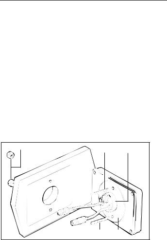
Mounting
3 |
2 |
1 |
2 |
|
4 |
|
|
D746-1 |
1 Cable boss 2 Fixing stud 3 Thumb nut 4 Sealing gasket

26 |
TYPE 100/300 Operation and Installation Handbook |
|
|
|
|
1.Makesurethatthemountingsurfaceissmooth andflat.
2.Use the template provided to mark the centres for the two fixing studs andthecableboss.
Note:Adjacentinstrumentsshouldhave6mm(1/4in)separationtoallow room for the protective covers.
3.Drill two 4mm (5/32in) diameter holes.
4.Using a 50mm (2in) diameter cutter, drill the hole for the cable boss (1).
5.Screw the two fixing studs (2) into the rear case of the control unit.
6.Passthecabletailsthroughthelargeholeandsecurethecontrolunit withthethumbnuts(3)provided.
Note: Thesealinggasket(4),isalreadyattachedtotherearcaseofthe control unit.
Cabling
ThecontrolunitisprovidedwithaSeaTalkcablefittedwitha3pinsocket oneachend.
1.PlugoneendofthecableintooneofthetwoSeaTalksocketsonthe back of the control unit.
2.RuntheSeaTalkcablebacktothecoursecomputer.
Note: Ifmorethanonecontrolunitisfitted,theSeaTalkcablecanbe connected to the free SeaTalk socket on the first control unit.
3.CuttheremainingplugfromtheSeaTalkcableandconnecttothethe SeaTalkterminalsonthecoursecomputer(asshowninthefollowing illustration).
|
|
– |
+ |
– |
+ |
SeaTalk |
SeaTalk CLUTCH |
POWER |
|||
Grey (screen) |
Red |
|
Yellow |
D1012-1 |
|
|
|
|
|
|
|

Chapter 2: Installation |
27 |
|
|
|
|
IfthevesselisalreadyfittedwithAutohelminstrumentation,thisshouldbe connectedtothecoursecomputerasshown,usingoneofthestandard SeaTalkinterfacecables.Thecoursecomputerwillthensupplypowerfor thecompletesystem.
|
|
|
ST50 Instrument |
|
ST7000 Control Unit |
|
|
– |
+ |
– |
+ |
+ |
+ |
+ |
+ |
+ |
|
|
|
|
|||
SeaTalk CLUTCH |
POWER |
|
|
|
|
||
|
|
|
+ |
+ |
+ |
+ |
+ |
Grey (screen) |
|
Red |
Yellow |
|
|
|
D1013-1 |
|
|
|
|
|
|
|
|
|
|
|
ST50 Instrument |
ST6000 Control Unit |
|||
– |
+ |
– |
+ |
+ |
+ |
+ |
+ |
+ |
|
|
|
|
|||
SeaTalk CLUTCH |
POWER |
|
|
|
|
||
|
|
|
+ |
+ |
+ |
+ |
+ |
Grey (screen) |
|
Red |
Yellow |
|
|
|
|
|
|
|
|
|
|
|
D1014-1 |
28 |
TYPE 100/300 Operation and Installation Handbook |
|
|
|
|
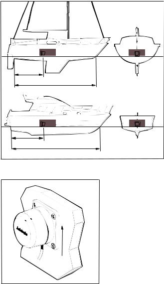
2.3 Fluxgate Compass
Correctpositioningofthefluxgatecompassiscrucialifultimateperformanceistobeachieved.Tominimisegimbaldisturbance,thefluxgate shouldideallybepositionedasnearaspossibletothepitchandrollcentre ofthevessel.
X |
Y |
0.3L to 0.5L
L
X |
Y |
0.3L to 0.5L
L
D194-2
Mounting
Vertical
D193-2

Chapter 2: Installation |
29 |
|
|
|
|
1.Locatethefluxgatecompassonasuitableverticalsurface.
2.Drillfourpilotholesandattachthefluxgatecompassusingtheselftappingscrewsprovided.
3.Makesurethatthefluxgateispositionedatleast0.8m(2ft6in)away fromthevessel’ssteeringcompassinordertoavoiddeviationofboth compasses.Toavoidcompassdeviationandreductioninsensitivity ofthesensor,thefluxgatemustalsobepositionedasfarawayas possiblefromlargeironmasses.
Note: If any doubt exists over magnetic suitability of the chosen site, the positionmaybesurveyedusingasimplehandbearingcompass.Thehand bearingcompassshouldbefixedinthechosenpositionandthevessel swungthrough360degrees.Relativedifferencesinreadingbetweenthe handbearingcompassandthevessel’smainsteeringcompassshould, ideally,notexceed10degreesonanyheading.
Cabling
1.Runthecablebacktothecoursecomputer.
2.Connectthetothefluxgateterminalsonthecoursecomputer.
|
|
FLUXGATE |
JOYSTICK |
|
Grey (screen) |
Red |
Green |
Yellow |
Blue |
|
|
|
|
D890-1 |
Note: A10m(30ft)extensioncableisavailableforlargerinstallations (part no. D174).
 Loading...