

Page 1
Modular Series
Master/Slave system
Master/Master system
User Manual
Page 2

Page 3
Modular Series
Master/Slave system
Master/Master system
User Manual
Page 4

Follow the indications and warnings given by the machine producer regarding the machine on which the radio remote control is installed.
If this manual is lost or damaged, ask for a copy from Autec. Please specify the serial number of the related radio remote control.
Contact AUTEC if any of the instructions and/or warnings given in this manual is not clear.
The information contained in this manual is subject to modification without notice and is not binding.
No part of this manual may be reproduced, in any form or by any means, without written permission of Autec (including recording and photocopying).
Page 5

INDEX
1 Introduction ...................................................................................... 2
1.1 Conventions.........................................................................................2
1.2 System description........................................................................ .. .....2
1.3 Conformity ..........................................................................................4
1.4 Risk analysis........................................................................................5
1.5 Documentation.....................................................................................5
1.6 Modular Series technical data... .. .............................. .. .. .. ........................6
1.7 Frequencies.........................................................................................6
2 Transmitting units ............................................................................. 7
2.1 Description of MK12 and MK10...............................................................7
2.2 Description of MJ.................... .. ........................... ... ........................... .. .8
2.3 Warnings for the use of the transmitting units..........................................9
2.4 Warnings for the maintenance of the transmitting units.......... ...................9
3 Receiving unit .................................................................................. 10
3.1 Description of the receiving unit ............................... .. .. .. ...................... 10
3.2 Inner parts of the “Master/Slave” receiving units .................................... 11
3.3 Inner parts of the “Master/Master” receiving units................................... 12
3.4 General warnings for the installation of the receiving unit ........................ 12
3.5 Specific warnings for the installation of the receiving unit......................... 14
3.6 Warnings for the maintenance of the receiving unit................................. 14
3.7 External signal lights of the receiving unit.............................................. 15
3.8 Internal signal lights of the receiving unit .............................................. 16
4 Operating mode of “Master/Slave” .................................................. 17
4.1 Command “Take/Release 2” or “Release 2” ............................................ 17
4.2 Power on and start up......................................................................... 18
5 Operating mode of “Master/Master”................................................ 19
5.1 Command “Take/Release” ................................................................... 19
5.2 Power on and start up......................................................................... 20
6 Operating mode of the transmitting units ........................................ 21
6.1 Command activation...................................... .. ............................ ....... 21
6.2 STOP................................................................................................ 22
6.3 Battery ............................................................................................. 22
6.4 Signals.............................................................................................. 22
6.5 Switching off.............................. .. ...................................................... 22
7 Maintenance .................................................................................... 23
7.1 Routine maintenance ............................. .. ........................... .. .. ............ 23
7.2 Special maintenance.................................... .. .. .. ............................ .. .. . 24
7.3 Disposal............................................................................................ 24
8 Programming ................................................................................... 25
8.1 Programming the transmitting module................................................... 25
8.2 Programming the receiving module................ .. .. ................................... 26
8.3 Programming the master board E16B14AC........................... .. ................ 27
8.4 Programming the bus board E16RI02_ ............... .. .. ... ........................... . 27
8.5 Frequency tables................................................................................ 27
LIMM&SA0-00.fm
9 Diagnostics ...................................................................................... 28
9.1 Transmitting unit diagnostics ........................................... .................... 28
9.2 Receiving unit diagnostics.................................................................... 29
- 1 -
Page 6
1 Introduction
1 INTRODUCTION
1.1 Conventions
In this manual, all important information is highlighted in the following symbols and conventions:
abcd…
abcd…
1.2 System description
Industrial radio remote controls of the Modular series are used to control machines from a distance.
Each industrial radio remote control is made up of at least one portable transmitting unit, from
which the user can remotely control the machine, and at least one receiving unit installed on
board the machine itself.
Each transmitting unit uses radio frequencies to transmit a coded message which contains a value called address. Each receiving unit can only decode the messages coming from its own transmitting unit with the same address.
This excludes the possibility of an interference activating any system function. If the radio transmission is disturbed, incorrect or interrupted, the receiving unit autonomously stops the whole
system thanks to the passive emergency function (passive stop).
WARNINGS
This symbol highlights all extremely important indications and in-
:
formation: failure to observe them could cause grave danger to
people or objects.
: IMPORTANT TEXTS
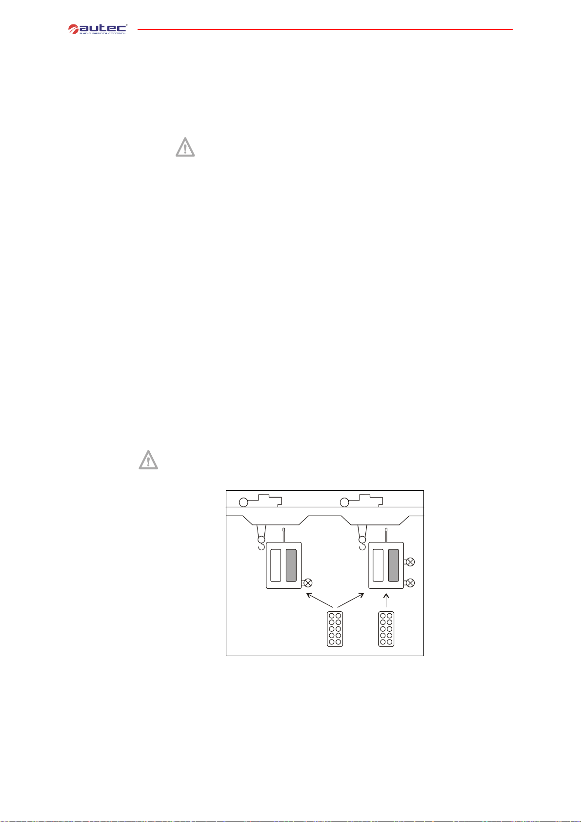
“Master/Slave”
system
The radio remote controls of the Modular series are equipped with a dual channel processing that protects the system “radio remote control+machine”, when it is in neutral (standstill) position, from unintended movements caused by possible radio
remote control single faults. Such safety function is only possible if the wiring instructions in the technical data sheet (see paragraph 1.5) and the regulations for correct
installation are respected (see paragraph 3.4 or paragraph 3.5).
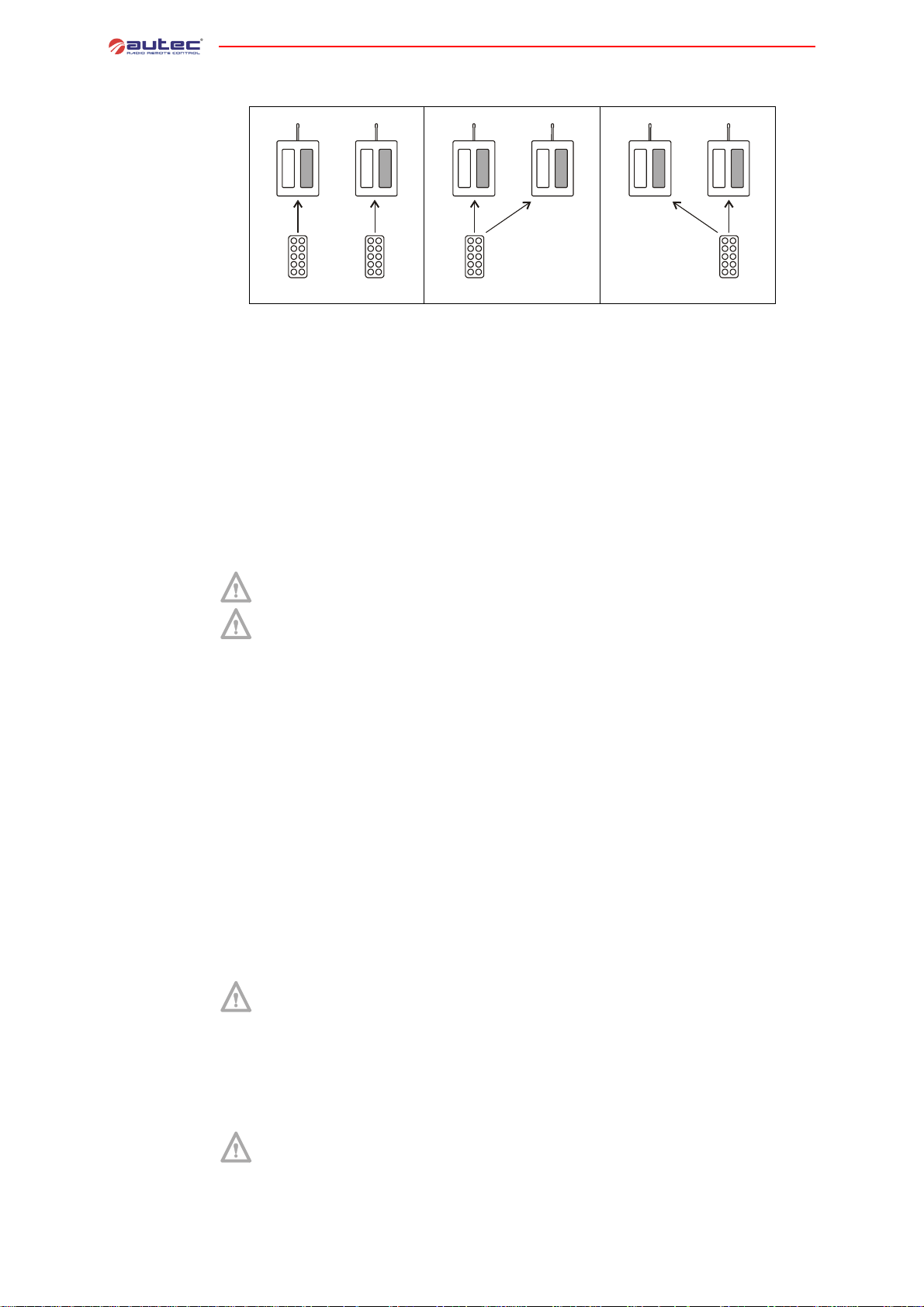
A “Master/Slave” system consists of two transmitting units (called UTX-M and UTX-S) and of two
receiving units (called URX-1 and URX-2).
A “Master/Slave” system is designed and implemented so that all its units always work in the same working application, and they cannot be split into two independent radio remote controls.
URX-1 URX-2
- 2 -
UTX-M
UTX-S
LIMM&SA0-00.fm
Page 7
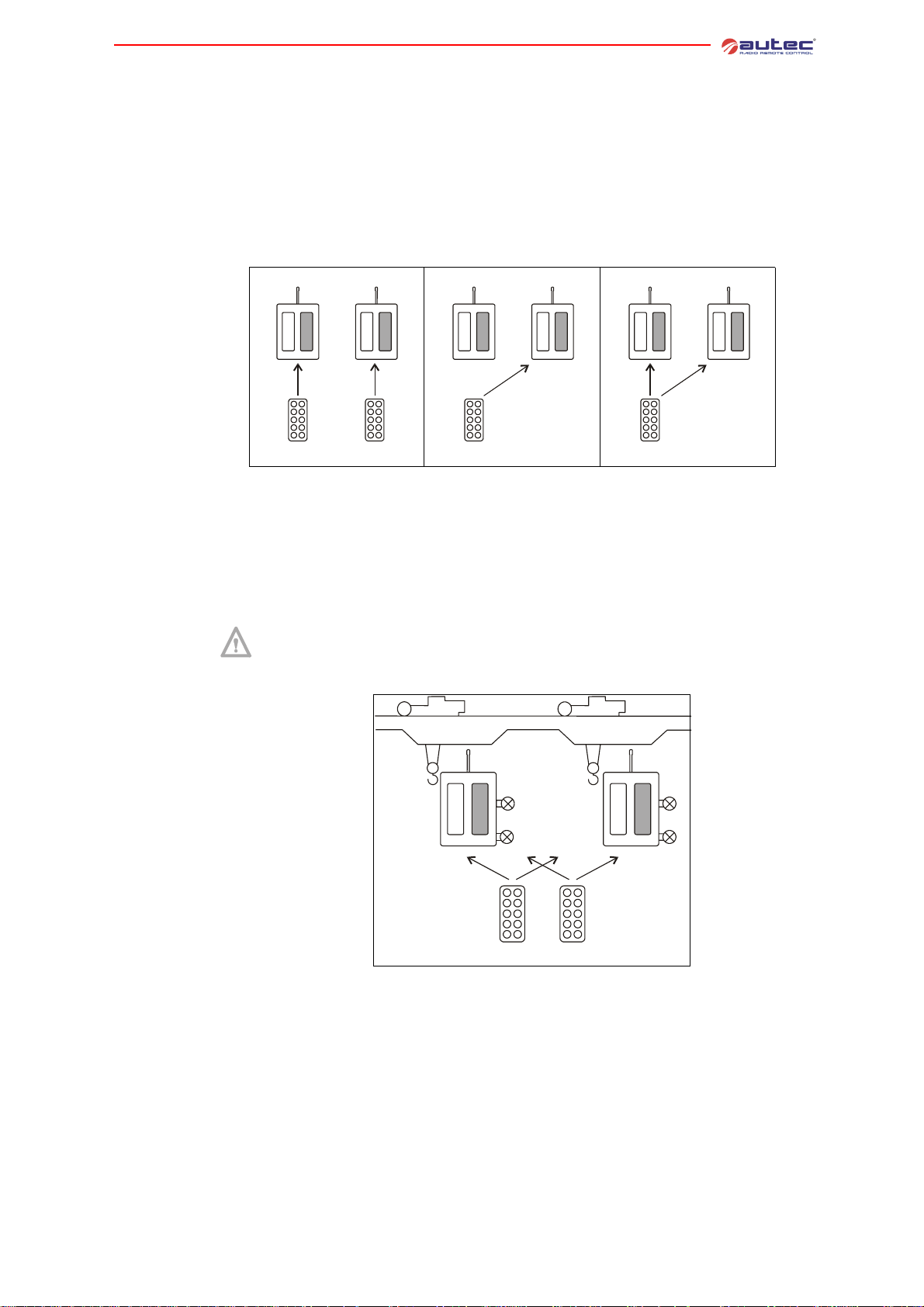
The transmitting unit UTX-M can work:
- in single mode, namely it can work with either of the two receiving units (either URX-1 or URX-
2)
- in tandem mode, namely it can work with both receiving units simultaneously
The transmitting unit UTX-S can only work in single mode with the receiving unit URX-2.
“Master/
Master” system
The receiving unit URX-1 can only be controlled by the transmitting unit UTX-M.
The receiving unit URX-2 can be controll ed by the two transmitting units, one at a time in an
independent and exclusive way.
URX-1 URX-2
UTX-M
UTX-S
URX-1 URX-2
UTX-M
URX-1 URX-2
UTX-M
Single mode Single mode Tandem mode
Radio transmission of a “Master/Slave” system uses two different addresses:
- one is used for the transmitting unit UTX-M, and can be decoded by both receiving units
- one is used for the transmitting unit UTX-S, and can only be decoded by the receiving unit
URX-2.
A “Master/Master” system consists of two transmitting units (called UTX-M and UTX-S) and of
two receiving units (called URX-1 and URX-2).
A “Master/Master” system is designed and implemented so that all its units always work in the same working application, and they cannot be split into two independent radio remote controls.
1 Introduction
URX-1 URX-2
UTX-M
UTX-S
The transmitting unit UTX-M can work:
- in single mode, namely it can work with either of the two receiving units (either URX-1 or URX-
2)
- in tandem mode, namely it can work with both receiving units simultaneously
The transmitting unit UTX-S can work:
- in single mode, namely it can work with either of the two receiving units (either URX-1 or URX-
2)
- in tandem mode, namely it can work with both receiving units simultaneously
The receiving unit URX-1 can be controll ed by the two transmitting units, one at a time in an
independent and exclusive way.
The receiving unit URX-2 can be controll ed by the two transmitting units, one at a time in an
independent and exclusive way.
LIMM&SA0-00.fm
- 3 -
Page 8
1 Introduction
URX-_ URX-_
URX-1 URX-2
URX-1 URX-2
UTX-M
Single mode Tandem mode Tandem mode
Radio transmission of a “Master/Master” system uses two differ ent addresses:
- one is used for the transmitting unit UTX-M, and can be decoded by both receiving units
- one is used for the transmitting unit UTX-S, and can be decoded by both receiving units
1.3 Conformity
Each Modular series radio remote control is in conformity with FCC Rules (Part 90 for
the transmitting unit and Part 15 for the receiving unit).
Operation is subject to the following two conditions:
1) this device may not cause harmful interference and
2) this device must accept any interference received, including interference that may
cause undesired operation.
Changes or modifications not expressly approved by the party responsible for
compliance could void the user’s authority to operate the equipment.
NOTE: This equipment has been tested and found to comply with the limits for a
Class B digital device, pursuant to Part 15 of the FCC Rules. These limits are designed to provide reasonable protection against harmful interference in a residential installation. This equipment generates, uses and can radiate radio
frequency energy and, if not installed and used in accordance with the instructions, may cause harmful interference to radio communications. However, there
is no guarantee that interference will not occur in a particular installation. If this
equipment does cause harmful interference to radio or television reception,
which can be determined by turning the equipment off and on, the user is encouraged to try to correct the interference by one or more of the following measures:
- reorient or relocate the receiving antenna
- increase the separation between the equipment and receiver
- connect the equipment into an outlet on a circuit different from that to which
the receiver is connected.
Consult the dealer or an experienced radio/TV technician for help.
UTX-S
UTX-M
UTX-S
Permitted uses
Forbidden uses
Working
conditions
- 4 -
Permitted applications are hoisting machines (construction cranes, bridge cranes,
machines for material handling in general,…).
Forbidden applications are:
- machines installed in areas where equipment with explosion-proof characteristics
is required
- machines for moving, raising and transporting people.
Autec cannot be held responsible if the radio remote control is installed on applications that are different from those permitted.
To guarantee correct radio remote control operation, all current regulations regarding safety at
work and accident prevention should be respected. All applicable standards and regulations valid
in the user country regarding the use of both the machine and the radio remote control must
always be respected.
Autec cannot be held responsible if the radio remote control is used in unlawful working conditions.
System must be installed by a licensed technician and in accordance with all relevant local, state/provincial and federal regulations, including but not limited to
NEC, OSHA, CE; etc.
LIMM&SA0-00.fm
Page 9
1.4 Risk analysis
All warnings listed in this manual have to be taken into account during risk analysis and when setting out protection measures.
All machines must undergo a risk analysis: it is therefore necess ary to evaluate, within the limits
of this analysis, if the machine can be radio remote controlled.
Some warnings and information for risk analysis for one or more machines controlled by a “Master/Slave” or “Master/Master” system are provided in this paragraph.
Following information is NOT exhaustive and/or DOES NOT replace requirements of current regulations in this field.
Risk analysis must always be carried out bearing in mind that the radio remote
control system consists of one or more transmitting units and of more receiving
units.
The machine producer and/or the person who decides upon radio remote control
use and installation is responsible for this analysis.
Autec cannot be held responsible if the risk analysis is not carried out correctly.
When carrying out risk analysis for the machine, the following aspects regarding the radio remote control have to be considered:
1.working application
2.loss of radio link
3.the un intended activation or loss of a command
1 Introduction
Working
application
Loss of radio link
Activation and
loss of a
command
Following has to be taken into account:
- wiring must guarantee correct o peration according to whet her the receiving u nit is installed
on a single machine or on different machines;
- if paired controls amongst the different machines are needed, the radio remote control c annot
guarantee synchronism between the different receiving units;
- if the remote controlled machines are not within the same vis ual field, the operator should
always be able to know which machines are being activated in a particular moment (i.e.
through an acoustic or light signal).
It must be taken into account the fact that radio link with one or more receiving units can be
lost due to radio interferences, power supply disconnection and electrical failures
Carefully evaluate which consequences such malfunction can have.
It must be taken into account that unintentional activation of a command and/or loss of command selection can be possible. Such unusual situations can be caused by electromechanical or
mechanical failure of the system “machine+radio remote control”.
Carefully evaluate which consequences such malfunction can have.
If required by the risk analysis, draw up protection measures to prevent, reduce
and report potential hazard situations.
1.5 Documentation
Instructions
for the
management of
documentation
Documentation enclosed with each radio remote control includes at least the following:
- instruction and warnings manual
- battery charger manual
-technical data sheet.
Make sure that such documents have been supplied: if they are not, please ask them
to Autec specifying the product serial number.
Technical data
sheet
LIMM&SA0-00.fm
The technical data sheet shows the wiring diagram between the receiving unit and the machine.
The technical data sheet must be filled in and checked by the installer, who is responsible for a
correct wiring. Once all necessary checks have been carried out, the installer m ust undersign
the technical data sheet, which must be kept wit h the user's manual (al ways keep a copy of this
data sheet for administrative purposes).
- 5 -
Page 10
Identification
plates
The radio remote control identification and approval data is given on plates that are on both the
transmitting unit and the receiving unit.
These plates MUST NOT be:
- removed from their position
- altered or damaged in any case.
1 Introduction
1.6 Modular Series technical data
Frequency band with radio module E16S_XEU1..................................... 902 - 928 MHz
Available radio channels ..................................................................................... 32
Hamming distance ............................................................................................ ≥ 8
Probability of undetected error................................................................ <10 exp-11
Typical working range ....................................................................... 330 ft [100 m]
Command response time .......................................................................... ~ 100 ms
STOP command response time
a
.................................................................. ~ 100 ms
Passive emergency time (or passive stop)
Safety function category according to the EN 954 - 1
STOP protection.............................................................................................Cat. 3
a. valid when the radio link between transmitting and receiving unit is not disturbed.
b. depending on DIP nr. 1 settings, see paragraph 8.2.
Due to the characteristics of radio propagation (i.e.: EM interferences, near outof-range condition), a delay up to one second may occasionally occur between
command release and actual deactivation of the corresponding output. Care
must be taken to ensure that this could never lead to a dangerous situation in the
specific uses.
1.7 Frequencies
The radio frequency of Autec radio remote controls is included in the group of frequencies permitted by regulations that are current at the moment of radio remote control
entry onto the market.
The two transmitting units UTX-M and UTX-S and the two receiving units URX -1 and URX-2 operate in manual selection mode: when operating in this mode it is possible to work at a specific
frequency that must be set manually by programming the dip switches in the radio modules (see
chapter 8).
b
................................................ 0.35/1 sec.
Frequencies
for the
“Master/Slave”
Frequencies
for the “Master/
Master”
Frequencies set in a “Master/Slave” system must undergo the following rules:
- the transmitting unit UTX-M and the transmitting unit UTX-S must work at two
different frequencies
- the receiving unit URX-1 must have the same working frequency as the transmitting unit UTX-M
- both working frequencies of the receiving unit URX-2 must be set as explained
in paragraph 3.2.
Frequencies set in a “Master/Master” system must undergo the following rules:
- the transmitting unit UTX-M and the transmitting unit UTX-S must work at two
different frequencies
- both working frequencies of the receiving unit URX-1 must be set as explained
in paragraph 3.3.
- both working frequencies of the receiving unit URX-2 must be set as explained
in paragraph 3.3.
- 6 -
LIMM&SA0-00.fm
Page 11
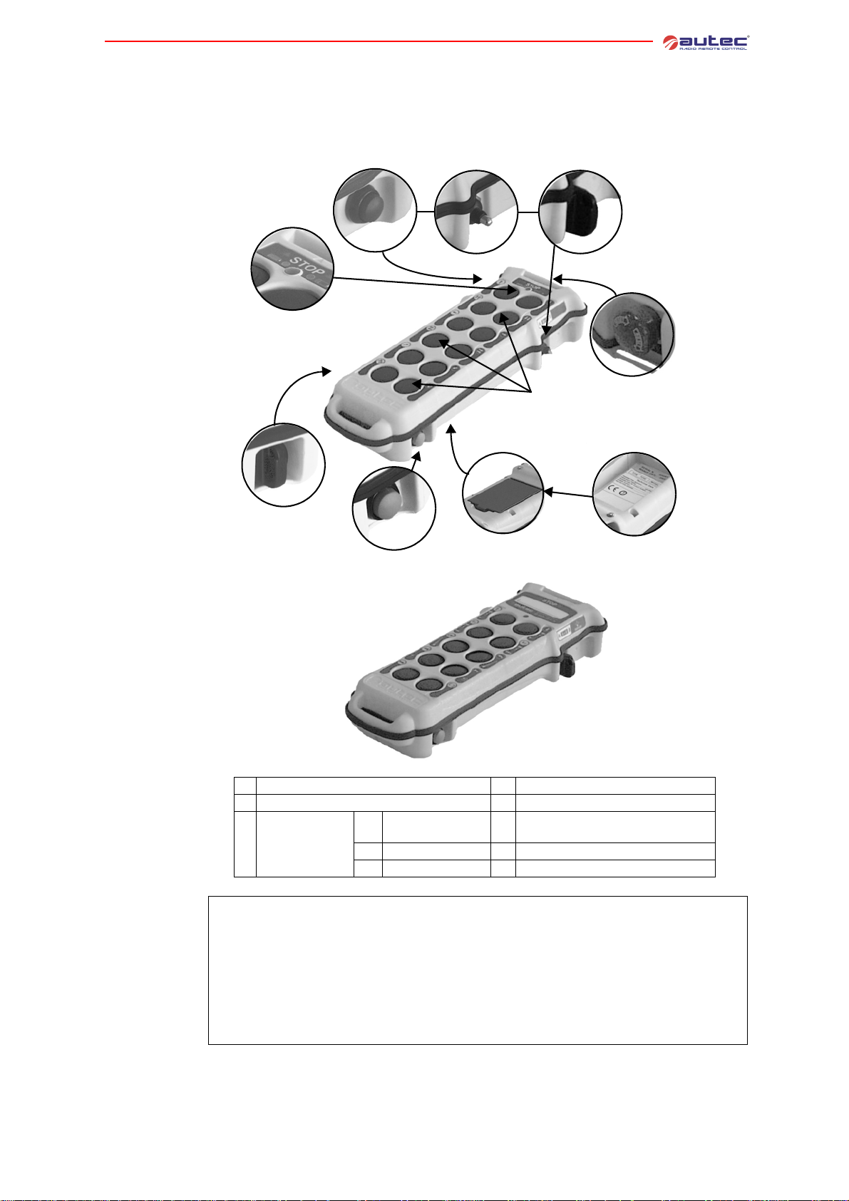
2 TRANSMITTING UNITS
2.1 Description of MK12 and MK10
MK12
MK10
(photos shown below only represent two of the possible configurations)
C1 C2 C3
C
C
B
A
E
H
G
F
2 Transmitting units
D
Technical data
LIMM&SA0-00.fm
A
starting keyswitch
B
signalling LED
Actuator
C
(if present)
C1
pushbutton
C2
toggle switch
C3
keyswitch selector
D
STOP pushbutton
E
pushbuttons
technical data plate, identification
F
plate (in the battery housing)
G
START pushbutton
H
battery
Power supply (battery pack MBM06MH)a................................................ NiMH 7.2 Vdc
Antenna .................................................................................................... internal
Battery capacity with fully charged battery (continuous use at 20°C)................ 15 hours
“Low battery” warning................................................................................. 3.5 min
Housing.............................................................................................PA 6 (20% fg)
Protection degree...............................................................................NEMA 4 [IP65]
Dimensions...................................................... 3.3" x 10.2" x 2" [85 x 260 x 50 mm]
Weight ............................................................................................1.4 lbs [650 g]
Transmitting power (frequency 433 MHz).... meets FCC Part 15 for free-license operation
Transmitting power (frequency 870 MHz).... meets FCC Part 15 for free-license operation
a. refer to battery technical data in the battery charger manual.
- 7 -
Page 12

2 Transmitting units
Climatic
conditions
Working
Storage
Transportation
2.2 Description of MJ
(photos shown below only represent a pos sible configuration)
MJ
Temperature Relative Humidity Air Pressure
Class 4K4H
-5°F to +130°F
(-20°C to +55°C)
Class 1K5
-40°F to + 160°F
(-40°C to +70°C)
Class 2K3
-13°F to + 160°F
(-25°C to +70°C)
4% to 100% (0,9 g/m
5% to 95% (1 g/m
Class 4K4H
Class 1K3
3
Class 2K3
95% (60 g/m
3
to 36 g/m3)
to 29 g/m3)
3
)
Class 4K4H
86 kPa to 106 kPa
Class 1K4
86 kPa to 106 kPa
Class 2K3
70 kPa to 106 kPa
A
B
H
Technical data
Climatic
conditions
G
C
F
E
D
A
actuators (joysticks and selectors)
B
STOP pushbutton
C
pushbutton and/or selector (optional)
identification plate and technical data
D
plate (in the battery housing)
E
battery (at the bottom)
F
signalling LED
G
START pushbutton
H
starting keyswitch
Power supply (battery pack MBM06MH)a................................................ NiMH 7.2 Vdc
Antenna .................................................................................................... internal
Battery capacity with fully charged battery (continuous use at 20°C)................ 14 hours
“Low battery” warning................................................................................. 3.5 min
Housing.............................................................................................PA 6 (20% fg)
Protection degree...............................................................................NEMA 4 [IP65]
Dimensions....................................................... 10" x 6.7" x 5"[255 x 170 x 126 mm]
Weight ............................................................................................2.9 lbs [1.3 kg]
Transmitting power (frequency 433 MHz).... meets FCC Part 15 for free-license operation
Transmitting power (frequency 870 MHz).... meets FCC Part 15 for free-license operation
a. refer to battery technical data in the battery charger manual.
Temperature Relative Humidity Air Pressure
Working
Storage
Transportation
Class 4K4H
-5°F to +130°F
(-20°C to +55°C)
Class 1K5
-40°F to + 160°F
(-40°C to +70°C)
Class 2K3
-13°F to + 160°F
(-25°C to +70°C)
4% to 100% (0,9 g/m
5% to 95% (1 g/m
Class 4K4H
Class 1K3
3
Class 2K3
95% (60 g/m
3
to 36 g/m3)
to 29 g/m3)
3
)
Class 4K4H
86 kPa to 106 kPa
Class 1K4
86 kPa to 106 kPa
Class 2K3
70 kPa to 106 kPa
- 8 -
LIMM&SA0-00.fm
Page 13
2.3 Warnings for the use of the transmitting units
FAILURE TO COMPLY WITH THE FOLLOWING WARNINGS MAR RESULT IN SERIOUS INJURY OR DEATH TO PERSONNEL AND DAMAGE TO EQUIPMENT.
The user must always respect the following warnings:
Autec, or its distributors, cannot be held responsible if the radio remote control
is installed on applications other than those permitted and if used in irregular
working conditions.
The operator should always ensure that both units are complete and that the
gaskets, bellows and hoods of the actuators (joysticks, selectors, pushbuttons)
are whole. If they are not, the radio remote control must not be used before being repaired.
Visually follow all movements of all remote controlled machines and of all correspondent loads; the user must therefore be in a position that offers the best visibility condition of the whole area.
Before using the radio remote control always make sure that the STOP pushbutton can be pressed and released: if it does not work, do not use the radio remote
control.
First switch on and start the transmitting unit, and then check that the STOP
pushbutton works properly: if the machine movements are not stopped when it
is activated, do not use the radio remote control.
Switch off the transmitting unit when work is interrupted. Avoid leaving the load
suspended in the air (even when changing the battery).
2 Transmitting units
Never leave the transmitting unit unguarded when the starting keyswitch is inserted.
Switch on or use the transmitting unit only when starting work: improper use
could be hazardous.
Never switch on or use the transmitting unit in closed spaces, with the machine
not in sight, or outside the typical working range.
When operating in tandem mode, always stay within the working range of both
receiving units, in order to facilitate radio link with each of them and to be sure
to control both receiving units.
Pay attention to the entire work area. Immediately press the STOP pushbutton
in case of hazard.
If the two machines do not have an alignment control system (see
paragraph 3.5), the user must be properly trained in order to operate correctly if
loss of alignment occurs.
In this case, immediately release the active command and/or activate the STOP
command.
Pay attention not to let elements such as concrete, sand, lime, etc. deposit on the
transmitting unit because they can compromise transmitting unit use and safety.
In case of malfunctions and/or damaged and/or faulty parts, put the radio remote control out of use until the problem has been completely eliminated.
2.4 Warnings for the maintenance of the transmitting units
Ensure that the battery has been removed from the transmitting unit before carrying out any maintenance work.
Any failures should be repaired by authorised Autec personnel using original Autec spare parts only.
LIMM&SA0-00.fm
In order to work with a unit that is always efficient an d safe, it is necess ary to carry out correctly
maintenance work (see chapter 7).
- 9 -
Page 14
3 Receiving unit
3 RECEIVING UNIT
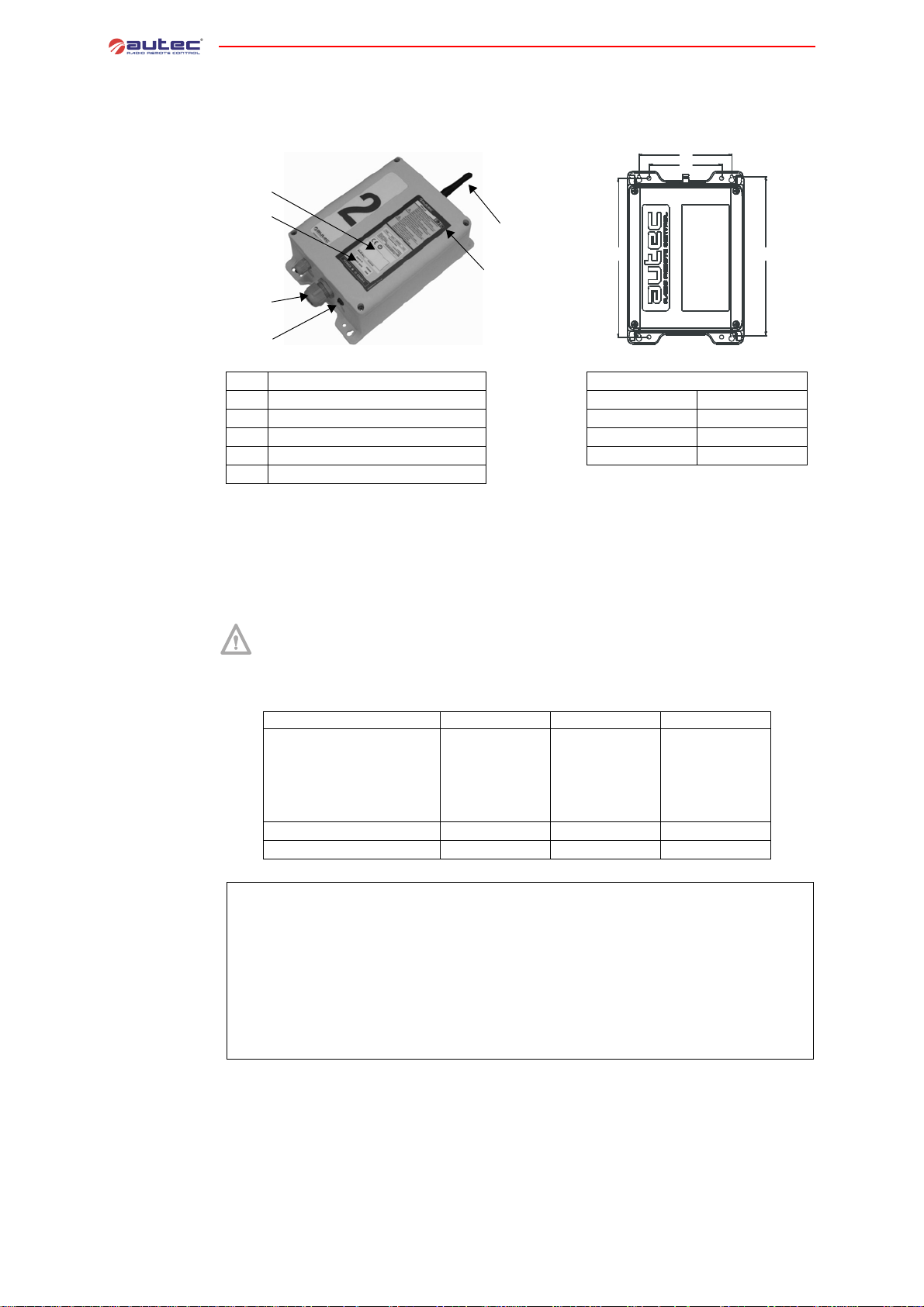
3.1 Description of the receiving unit
C
B
G
H
E
Receiving unit
technical data
L
M
F
A
D
A
cable gland (opt. plug)
B
identification plate
C
technical data plate
D
POWER ENABLE light
E
antenna
F
“ENABLED” lights (if present)
Drilling template
G
H
L
M
5.8” (148 mm)
4.6” (116 mm)
10” (253 mm)
10” (253 mm)
Number 1 or 2 on the receiving unit identifies respectively URX-1 and URX-2.
These receiving units are equipped with a s afety function called SAFETY that protects the system
“machine+radio remote control” from unintended move ments, namely machine movemen ts not
activated intentionally by the user, but by possible elect rical or me chanical failure of the radio
remote control. Such safety function protects from failure the neutral (rest) positio n of the ac tuators in the radio remote control.
The SAFETY function is only active if both the wiring instructions in the technical
data sheet and the prescriptions for correct installation included in the following
manual are respected.
Supply voltage (POWER SUPPLY)
Min. Nom. Max
25
35
50
110
230
11
30
42
62
132
250
Voltage (Vac)
Frequency (Hz)
Absorbed power (VA)
18
25
36
70
150
50 60
- 10 -
Antenna ................................................................................................. dedicated
STOP contact rated current .................................................................. 4 A (250 Vac)
SAFETY contact rated current............................................................... 4 A (250 Vac)
Command contact rated current...........................................................6 A (250 Vac)
Fuse F1 (POWER SUPPLY)....................................... 1.25 A T 250 V [0.2”x0.8” (5x20 mm)]
Fuse F2 and F3 (STOP circuit).......................................4 A T 250 V [0.2”x0.8” (5x20 mm)]
Fuse F4 and F5 (SAFETY circuit).................................... 4 A T 250 V [0.2”x0.8” (5x20 mm)]
Housing.............................................................................................PA 6 (20% fg)
Protection degree...............................................................................NEMA 4 [IP65]
Dimensions........................................................ 7.1” x 9.1” x 3.7” [180 x 230 x 95 mm]
Weight........................................................................................................................... 5.7 lbs [2.6 kg]
a. the rated current of commands contacts for the optional modules that may be present is indi-
cated in the technical data sheet
LIMM&SA0-00.fm
a
Page 15
Climatic
conditions
Working
Storage
Transportation
Temperature Relative Humidity Air Pressure
Class 4K4H
-5°F to +160°F
(-20°C to +70°C)
Class 1K5
-40°F to + 160°F
(-40°C to +70°C)
Class 2K3
-13°F to + 160°F
(-25°C to +70°C)
4% to 100% (0,9 g/m
5% to 95% (1 g/m
Class 4K4H
Class 1K3
3
Class 2K3
95% (60 g/m
3
to 36 g/m3)
to 29 g/m3)
3
)
3.2 Inner parts of the “Master/Slave” receiving units
Class 4K4H
86 kPa to 106 kPa
Class 1K4
86 kPa to 106 kPa
3 Receiving unit
Class 2K3
70 kPa to 106 kPa
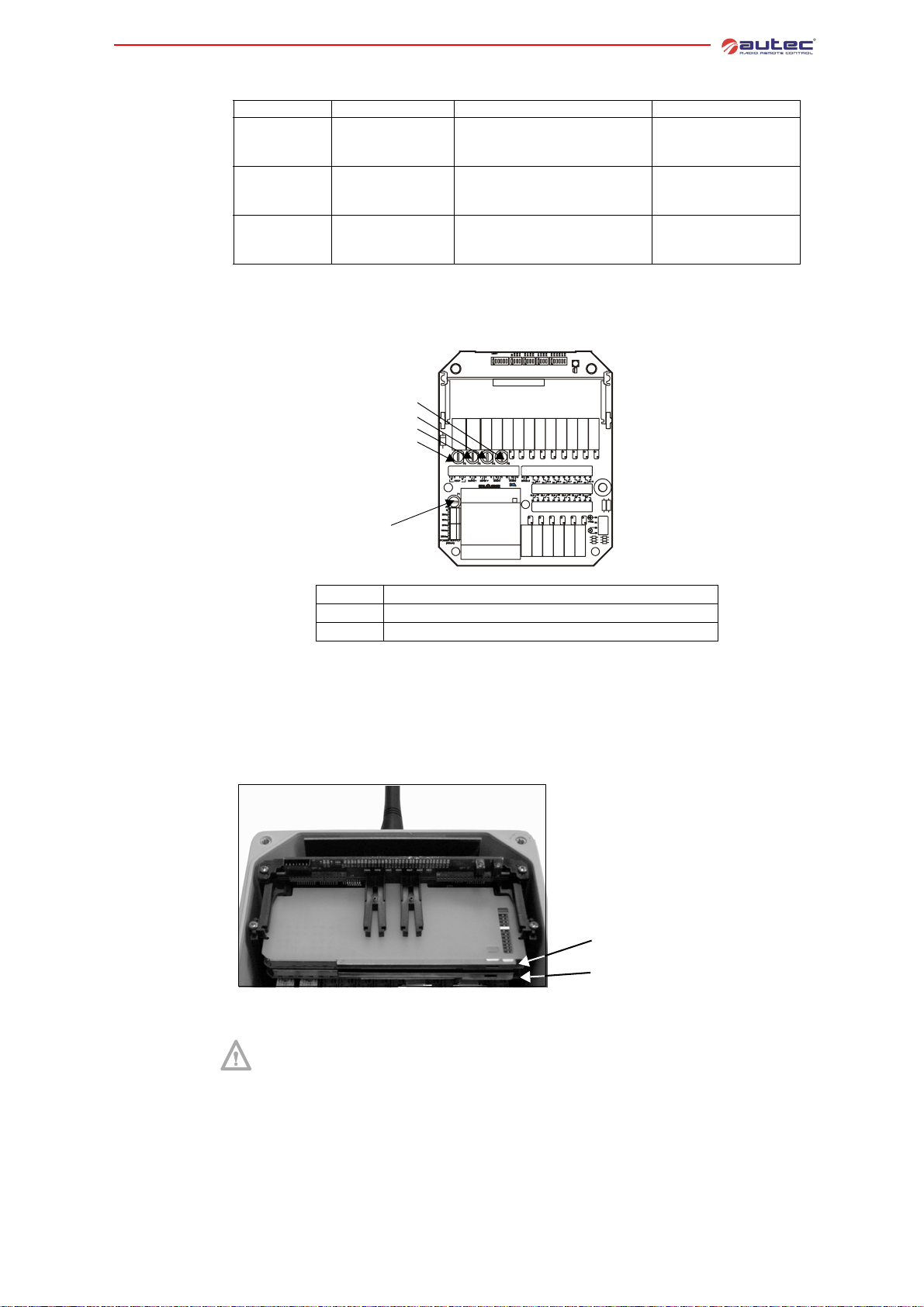
Mother board
Bus board of the
unit URX-1
Bus board of the
unit URX-2
The mother board in the receiving units is the E16B14AC.
F5
F4
F3
F2
F1
F1
POWER SUPPLY protection fuse
F2 and F3
F4 and F5
STOP circuit protection fuses
SAFETY circuit protection fuses
The receiving unit URX-1 contains the bus board E16RI02B.
See paragraph 8.4 to program the bus board E16RI02B.
The receiving unit URX-2 contains the bus board E16RI02D, where two radio receiving module
have their seats; the one corresponds to the transmitting unit UTX-M and the other to the UTXS.
LIMM&SA0-00.fm
Radio receiving module
corresponding to the UTX-S
Radio receiving module
corresponding to the UTX-M
Position of the two radio receiving module is the one showed in the previous photo.
Frequencies set in the two radio receiving modules must undergo the following
rules:
- the radio receiving module corresponding to the transmitting unit UTX-M must
have the same working frequency as the transmitting unit UTX-M
- the radio receiving module corresponding to the transmitting unit UTX-S must
have the same working frequency as the transmitting unit UTX-S.
See paragraph 8.4 to program the bus board E16RI02D.
- 11 -
Page 16
3.3 Inner parts of the “Master/Master” receiving units
3 Receiving unit
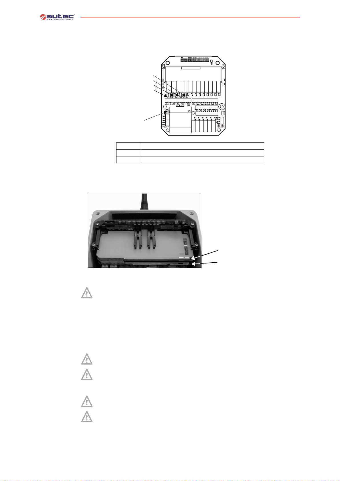
Mother board
Bus board
The mother board in the receiving units is the E16B14AC.
F5
F4
F3
F2
F1
F1
POWER SUPPLY protection fuse
F2 and F3
F4 and F5
STOP circuit protection fuses
SAFETY circuit protection fuses
The receiving units URX-1 and URX-2 contain the bus board E16RI02D, where two radio receiving module have their seats; the one corresponds to the transmitting unit UTX-M and the other
to the UTX-S.
Radio receiving module
corresponding to the UTX-S
Radio receiving module
corresponding to the UTX-M
Position of the two radio receiving module is the one showed in the previous photo.
Frequencies set in the two radio receiving modules must undergo the following
rules:
- the radio receiving module corresponding to the transmitting unit UTX-M must
have the same working frequency as the transmitting unit UTX-M
- the radio receiving module corresponding to the transmitting unit UTX-S must
have the same working frequency as the transmitting unit UTX-S
See paragraph 8.4 to program the bus board E16RI02D.
3.4 General warnings for the installation of the receiving unit
FAILURE TO COMPLY WITH THE FOLLOWING WARNINGS MAR RESULT IN SERIOUS INJURY OR DEATH TO PERSONNEL AND DAMAGE TO EQUIPMENT.
Installation must only be carried out by qualified people and in accordance with
installation country rules.
The installer must always respect the following warnings:
Place the receiving unit vertically, with the cable gland (or plug) facing down.
- 12 -
Install the receiving unit so that the radio link is facilitated.
- the receiving unit must not be shielded by metal objects
- the antenna stylus must be at least 50 cm far from metal objects in its surroundings
WARNING: If the receiving unit is covered by metal structures or installed inside
metal cabinets, use the appropriate extension kit for the antenna.
LIMM&SA0-00.fm
Page 17
In this case, install the antenna in a vertical position, and possibly place it near
the work area.
Place the receiving unit so that it can be reached easily.
Fix the receiving unit in 4 points, using the specific holes in the housing and the
specific vibration dampers.
Do not modify or tamper with the radio remote control, the machine or its electrical panel. Do not perforate the receiving unit in any case.
Check that the receiving unit power supply is within the voltage range given in
the “Technical Data”, and that the voltages and currents being used do not exceed the maximum permitted values.
Do not bypass the radio remote control safety devices and/or those present inside the machine.
Respect the IEC60204-32 (for hoisting machines) and/or IEC60204-1 prescriptions (for machines).
Never power on the receiving unit directly from the mains. A main switch should
always be present to allow power supply removal.
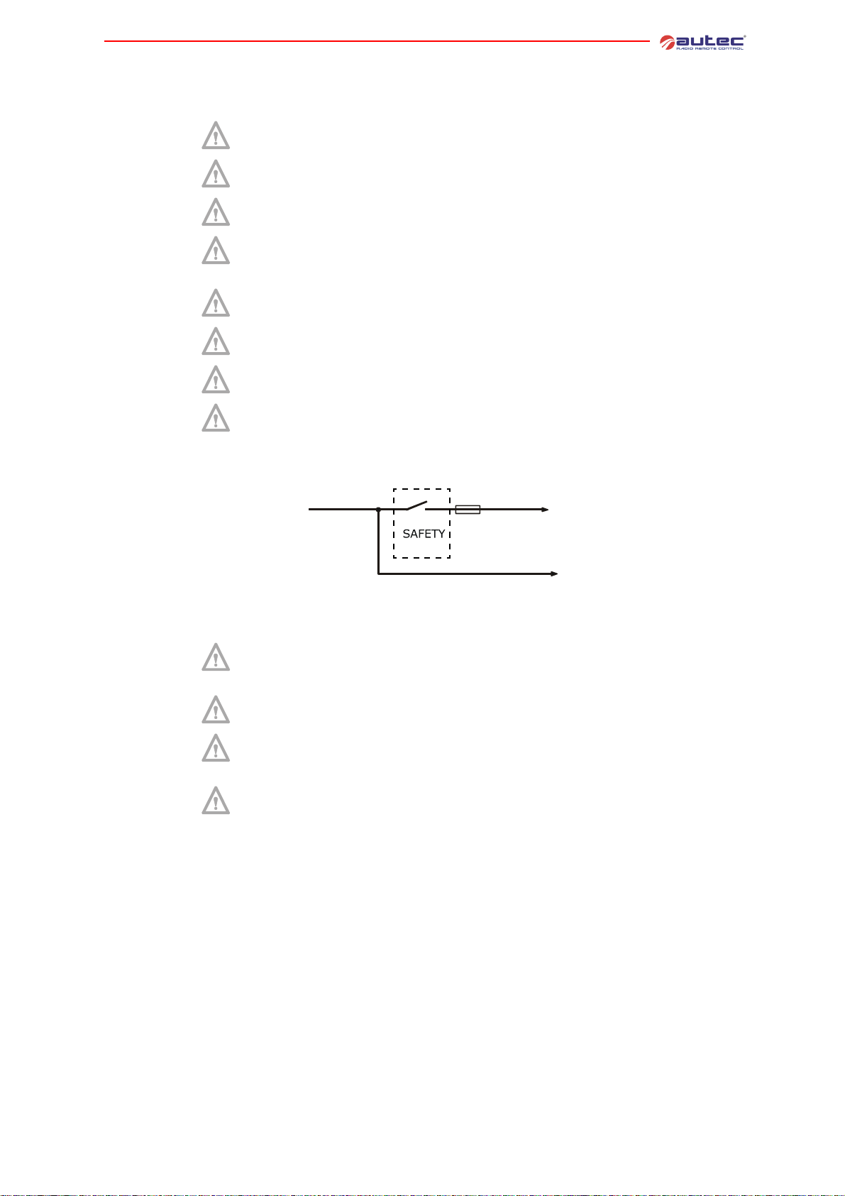
Remember to carefully wire the SAFETY contact in series with the movement
commands inside the receiving unit.
(wiring example)
Receiving unit
3 Receiving unit
common
input
Fuse
movement command
common wire
selection and/or
auxiliary command
common wire
After installation and wiring, always check that the manoeuvres carried out are
exactly the same as the commands given (in particular check the STOP command).
Group the wiring away from the radio modules in order to avoid interferences
and hazards related to electrical safety.
Never remove the jumper between the STOP-command contacts 2 and 3, unless
a circuit with 2 separate contacts (4 wires) is required. If removed, the STOP circuit could loose its safety functions.
When maintenance is carried out on the machine (i.e. when soldering), remove
power supply by disconnecting all electric connections (both during installation
and during normal operation).
The installer must CHECK and/or FILL IN the “Technical Data Sheet”, indicating the date the system has been put into service, signing and stamping it.
LIMM&SA0-00.fm
- 13 -
Page 18
3.5 Specific warnings for the installation of the receiving unit
3 Receiving unit
IEC60204
Wiring
Radio link
Alignment
control
Pursuant to section 9.2.7.5 of the IEC60204-1 (and IEC60204-32), installation of two
different lamps (or horns) in the receiving units, connected to the dedicated terminals
ENA-M and ENA-S (as explained in the technical data sheet) is recommended.
These two signal devices indicate the working status of the receiving units (see
chapter 4 for the “Master/Slave” system and chapter 5 for the “Master/Master” system).
The installer must carry out wiring and/or check that this one assure s correct operation of the
machines working together.
Wiring is fundamental for the system to operate in a correct and safe way, as it
is for all radio remote controls with different receiving units. In some cases wiring could be the only way to implement any possible measure for risk reduction.
For example, given the possibility to use the same commands in different receiving units on different machines or parts of a machine, it is fundamental to carry out appropriate wiring to implement any possible measure for risk prevention, reduction and signalling in the various
situations.
Install the two receiving units and their antennas so that the radio link is facilitated.
- minimum distance between the two units or antennas must be more than 3
meters
- maximum distance between the two units or antennas must be shorter than
twice the typical working range of the radio remote control
While operating in tandem mode, if unusual adverse conditions occur (such as electromagnetic
disturbance, interferences or failure and disconnection) a transmitting u nit could lose radio link
with only one of the two receiving units. Correct installation of the two receiving units reduce s
considerably likelihood that such a situation occurs because of radioelectrical causes.
A “Master/Slave” or “Master/Master” system does non assure alignment between the remote controlled machines: if required in the risk analysis, it must be
installed an alignment control system that intervenes properly.
3.6 Warnings for the maintenance of the receiving unit
Ensure that the receiving unit has been disconnected from the power source before carrying out any maintenance work.
Any failures should be repaired by authorised Autec personnel using original Autec spare parts only.
In order to work with a unit that is always efficient an d safe, it is necess ary to carry out correctly
maintenance work (see chapter 7).
- 14 -
LIMM&SA0-00.fm
Page 19

3.7 External signal lights of the receiving unit
POWER ENABLE
light
ENABLED lights
in “Master/
Slave”
Each receiving unit is equipped with a status indicating light:
Signal type Meaning
Light switched off
Steady light
Blinking light
receiving unit not powered on
receiving unit powered on
(POWER ON)
radio link between transmitting and
receiving unit is present (ENABLE ON)
The receiving unit URX-2 has two “ENABLED” lights that indicate its status in relation to the
transmitting units:
Signal type ENABLED UTX-M ENABLED UTX-S
Light off
Steady light
the receiving unit URX-2 is free from
the transmitting unit UTX-M
the receiving unit URX-2 is engaged by
the transmitting unit UTX-M
the receiving unit URX-2 is free from
the transmitting unit UTX-S
the receiving unit URX-2 is engaged by
the transmitting unit UTX-S
ENABLED UTX-M
ENABLED UTX-S
3 Receiving unit
ENABLED lights
in “Master/
Master”
The receiving units have two “ENABLED” lights that indicate their status in relation to th e transmitting units:
Signal type ENABLED UTX-M ENABLED UTX-S
Light off
in the unit URX-1
Steady light
in the unit URX-1
Light off
in the unit URX-2
Steady light
in the unit URX-2
the receiving unit URX-1 is free from
the transmitting unit UTX-M
the receiving unit URX-1 is engaged by
the transmitting unit UTX-M
the receiving unit URX-2 is free from
the transmitting unit UTX-M
the receiving unit URX-2 is engaged by
the transmitting unit UTX-M
the receiving unit URX-1 is free from
the transmitting unit UTX-S
the receiving unit URX-1 is engaged by
the transmitting unit UTX-S
the receiving unit URX-2 is free from
the transmitting unit UTX-S
the receiving unit URX-2 is engaged by
the transmitting unit UTX-S
LIMM&SA0-00.fm
- 15 -
Page 20

3.8 Internal signal lights of the receiving unit
3 Receiving unit
Relay LEDs
LED on the radio
module
LEDs in the
bus board
The activation of each relay on the mother board E16B14AC is signalled by a LED (A) near the
relay. The same indication is also given in the bus board (E16RI02_).
Mother board E16RI02_ bus board
A
A
Three LEDs are present on the receiving module, that indicate:
1.power supply on
2.radio link on
3.frequency scanning search
Two diagnostic LEDs are present both on the bus board E16RI02B and on the bus board
E16RI02D indicating:
LEDs Meaning
LED 3 (green)
LED 4 (red)
123
power supply on
code alarm in the data memory (see
paragraph 9.2)
The lights ENABLED UTX-M and ENABLED UTX-S (see paragraph 3.7) are also present in the bus
board E16RI02D.
LED 4
LED 3
ENABLED UTX-M
ENABLED UTX-S
- 16 -
LIMM&SA0-00.fm
Page 21

4 OPERATING MODE OF “MASTER/SLAVE”
4.1 Command “Take/Release 2” or “Release 2”
Transmitting
unit UTX-M
1
2
POWER ON AND
START UP
POWER ON AND
START UP
2
1
The transmitting unit UTX-M has a “Take/Release 2” command that engages and releases the
receiving unit URX-2.
In order for the transmitting unit UTX-M to take control of the receiving unit URX-2 during start
up or working:
- press the START pushbutton and do not release it until the lamp (or horn) ENA-M of the receiving unit URX-2 switches on with ON blinking fast
- activate the “Take/Release 2” command within 3 seconds
A steady ON signal of the lamp (or horn) ENA-M indicates that the connection has succeeded.
COMMAND
“TAKE/RELEASE 2” OR
“RELEASE 2”
COMMAND
“TAKE/RELEASE 2”
OR “RELEASE 2”
4 Operating mode of “Master/Slave”
Transmitting
unit UTX-S
From now on, the transmitting unit UTX-M completely controls the receiving unit U RX-2, which
cannot be used by the transmitting unit UTX-S.
In order to release the receiving unit URX-2, activate the command “Take/Release 2” again. An
OFF status of the lamp (or horn) ENA-M confirms that the unit has been rele ased. When the
transmitting unit UTX-M is switched off but has not released the receiving unit URX-2, the lamp
(or horn) ENA-M stays ON blinking slowly.
The transmitting unit UTX-S has a “Rel ease 2” command to release the receiving unit URX-2.
During start up the transmitting unit UTX-S engages automatically the receiving unit URX-2, if
it is free: press the START pushbutton and do not release it until the lamp (or horn) ENA-S
switches on with steady ON.
From now on, the transmitting unit UTX-S completely controls the receiving unit URX-2, which
cannot be used by the transmitting unit UTX-M.
In order to release the receiving unit URX-2, activate the command “Release 2”. An OFF status
of the lamp (or horn) ENA-S confirms that the un it has been released. When th e transmitting
unit UTX-S is switched off but has not released the receiving unit URX-2, the lamp (or horn)
ENA-S stays ON blinking slowly.
LIMM&SA0-00.fm
- 17 -
Page 22
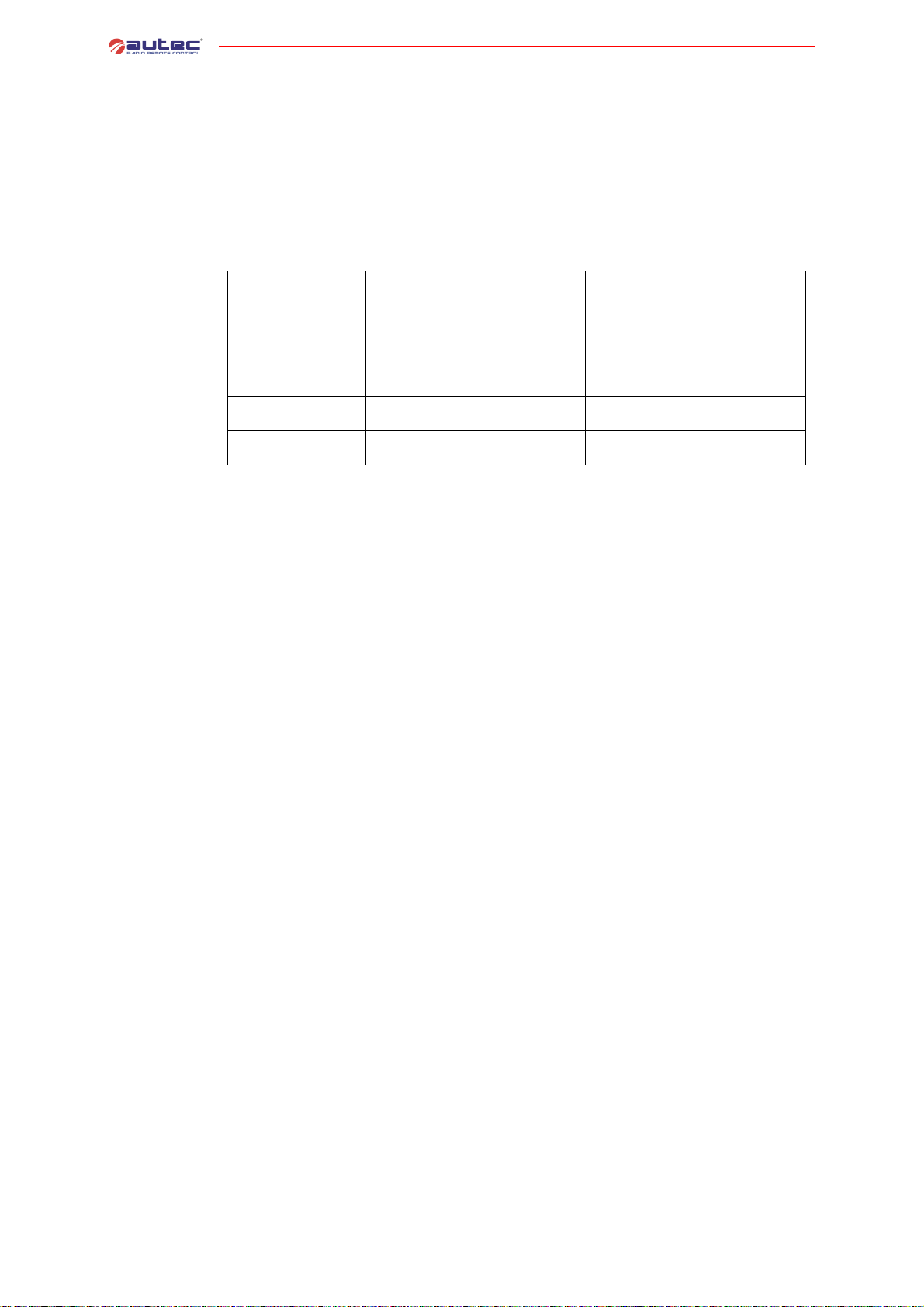
Status of the
receiving unit
URX-2
The receiving unit URX-2 has three working modes:
- free: it can be used by the transmitting unit that first requests its control. The receiving unit
has this status when the lamps or horns (if present) are not switched on
- engaged: it is reserved but not used by one of the transmitting units, which is off. It cannot
be used by the other transmitting unit until it is released and the refor e set to the fre e st atus
by the transmitting unit that is controlling it. The receiving unit has this status when one of
the two lamps (or horns) ENA-M or ENA-S is ON blinking slowly
- engaged and used: it is reserved and used by one of the two transmitting units and cannot
be used by the other until it is released and therefore se t to the free status by the transmitt ing
unit that is controlling it. The receiving unit has this statu s when one of the la mps or horns (if
present) is not switched on.
4 Operating mode of “Master/Slave”
4.2 Power on and start up
Transmitting
unit UTX-M
Signal type
OFF
ON blinking
fast (3 sec.)
steady ON
ON
blinking slowly
LAMP (OR HORN)
connected to the terminal
ENA-M
the receiving unit URX-2 is free from
the transmitting unit UTX-M
the receiving unit URX-2 waits to be
engaged by the transmitting unit UTXM (during start up)
the receiving unit URX-2 is used by the
transmitting unit UTX-M
the receiving unit URX-2 is engaged by
the transmitting unit UTX-M
the receiving unit URX-2 is free from
the transmitting unit UTX-S
the receiving unit URX-2 is used by the
transmitting unit UTX-S
the receiving unit URX-2 is engaged by
the transmitting unit UTX-S
LAMP (OR HORN)
connected to the terminal
ENA-S
//
A transmitting unit that has engaged the receiving unit URX-2 keeps control on it even
after the STOP pushbutton has been activated or after the transmitting unit has been
switched off.
The receiving unit URX-2 gets back to its free status:
- if it is disconnected from its power source
- if it is released by the transmitting unit that had engaged it; release takes place
when the “Take/Release 2” or “Release 2” command is activated.
The following procedure allows the transmitting unit UTX-M to work with the receivin g unit URX1 only (single mode):
1.To switch on the transmitting unit UTX-M, insert the starting keyswitch and turn it to “I” position.
2.To start the radio remote control functions, press the START pushbutton for 3-4 seconds. After
start up, the green signalling LED in the transmi tting unit always lights up.
Transmitting
unit UTX-S
In order to engage the receiving unit URX-2 (single or tandem mode), follow the procedure in
paragraph 4.1.
In order to activate commands, follow instructions given in paragraph 6.1.
The following procedure allows the transmitting unit UTX-S to engage the receiving unit URX-2
when it is free (single mode):
1.To switch on the transmitting unit UTX-S, insert the starting keyswitch and turn it to “I” position.
2.In order to start the functions of the radio remote control, keep the START pushbutton pressed
until the lamp (or horn) ENA-S switches ON steadily. After start up, the green signalling
LED in the transmitting unit always lights up.
- 18 -
LIMM&SA0-00.fm
Page 23
5 OPERATING MODE OF “MASTER/MASTER”
5.1 Command “Take/Release”
1
“TAKE/RELEASE 2”
COMMAND
“TAKE/RELEASE 1”
COMMAND
POWER ON AND
START UP
POWER ON AND
START UP
2
The transmitting unit UTX-M and the transmitting unit UTX-S have a “Take/Release 1” command
and a “Take/Release 2” command that engage and release respectively the receiving unit URX1 and the receiving unit URX-2.
In order for one of the transmitting units take control of a receiving unit during start up or working:
- press the START pushbutton and do not release it until the lamps (or horns) ENA-M or ENA-S
of the receiving units switches on with ON blinking fast
- activate within 3 seconds the “Take/Release” command related to the receiving unit to be engaged
A steady ON signal of the related lamp (or horn) indicates that the connect ion h as s uc cee ded.
2
COMMAND
“TAKE/RELEASE 2”
1
COMMAND
“TAKE/RELEASE 1”
5 Operating mode of “Master/Master”
Receiving units
status
LIMM&SA0-00.fm
From now on, the transmitting unit completely controls the receiving unit, which cannot be used
by the other transmitting unit.
In order to release the receiving unit, activate once again the corresponding “Take/Release”
command. An OFF status of the related lamp (or horn) confirms that th e unit has been released.
When a transmitting unit is switched off without having released a receiving unit, the related
lamp (or horn) is ON blinking slowly.
The two receiving units have three working modes:
- free: it can be used by the transmitting unit that first requests its control. The receiving unit
has this status when the lamps or horns (if present) are not switched on
- engaged: it is reserved but not used by one of the transmitting units, which is off. It cannot
be used by the other transmitting unit until it is released and ther efore se t to th e fre e statu s
by the transmitting unit that is controlling it. The receiving unit has this status when one of
the two lamps (or horns) ENA-M or ENA-S is ON blinking slowly
- engaged and used: it is reserved and used by one of the two transmitting units and cannot
be used by the other until it is released and therefore se t to the free status by the transmitt ing
unit that is controlling it. The receiving unit has this statu s when one of the la mps or horns (if
present) is not switched on.
- 19 -
Page 24

5 Operating mode of “Master/Master”
Signal type
OFF
ON blinking
fast (3 sec.)
steady ON
ON
blinking slowly
connected to the terminal
the receiving unit URX-1 or URX-2 is
free from the transmitting unit UTX-M
the receiving unit URX-1 or URX-2 waits
to be engaged by the transmitting unit
UTX-M (during start up)
the receiving unit URX-1 or URX-2 is
used by the transmitting unit UTX-M
the receiving unit URX-1 or URX-2 is
engaged by the transmitting unit UTX-M
A transmitting unit that has engaged a receiving unit keeps control on it even after the
STOP pushbutton has been activated or after the transmitting unit has been switched
off.
A receiving unit gets back to its free status:
- if it is disconnected from its power source
- if it is released by the transmitting unit that had engaged it; release takes place
when the “Take/Release” command is activated.
5.2 Power on and start up
Follow this procedure to switch on and start up the transmitting units:
1.To switch on a transmitting unit, insert the starting keyswitch and turn it to “I” position.
2.To start the radio remote control functions, press the START pushbutton without releas ing it
for 3-4 seconds. In order to engage a receiving unit, follow the procedure in paragraph 5.1.
After start up, the green signalling LED in the transmitting unit always lights up.
LAMP (OR HORN)
ENA-M
LAMP (OR HORN)
connected to the terminal
ENA-S
the receiving unit URX-1 or URX-2 is
free from the transmitting unit UTX-S
the receiving unit URX-1 or URX-2 waits
to be engaged by the transmitting unit
UTX-S (during start up)
the receiving unit URX-1 or URX-2 is
used by the transmitting unit UTX-S
the receiving unit URX-1 or URX-2 is
engaged by the transmitting unit UTX-S
In order to engage the receiving unit, follow the procedure in paragraph 5.1.
In order to activate commands, follow instructions given in paragraph 6.1.
- 20 -
LIMM&SA0-00.fm
Page 25

6 OPERATING MODE OF THE TRANSMITTING UNITS
COMMAND
ACTIVATION
STOP
SWITCHING OFF
SIGNALS
BATTERY
SWITCHING OFF
SIGNALS
6.1 Command activation
Activate the joysticks, pushbuttons and/or selectors related to any of the movement or selection
commands to be carried out.
Selector
1/1+2/2 in a
Master/Slave
The transmitting unit UTX-M has a selector 1/1+2/2 to select the working position:
- position 1 (single mode): the transmitting unit UTX-M works with the receiving unit URX-1
- position 1+2 (tandem mode): the transmitting unit UTX-M works bot h with the receivin g unit
URX-1 and the receiving unit URX-2 (in this case the transmitting unit UTX-M must previously
engage the receiving unit URX-2: see paragraph 4.1)
- position 2 (single mode): the tran smitting uni t UTX-M works wi th the receivin g unit URX-2 ( in
this case the transmitting unit U TX-M mus t previously en gage the re ceiving unit URX-2: see
paragraph 4.1)
COMMAND
ACTIVATION
6 Operating mode of the transmitting units
STOP
BATTERY
Selector
1/1+2/2 in a
Master/Master
LIMM&SA0-00.fm
The transmitting units UTX-M and UTX-S have a selector 1/1+2/2 to sele ct the working position:
- position 1 (single mode): the transmitting unit works with the receiving unit URX-1
- position 1+2 (tandem mode): the transmitting unit works both with the receiving unit URX-1
and with the receiving unit URX-2
- position 2 (single mode): the transmitting unit works with the receiving unit URX-2
Selection of the desired position with the toggl e switch is only possible after the transmitting
unit has engaged the receiving unit/s needed for working (see paragraph 5.1).
- 21 -
Page 26
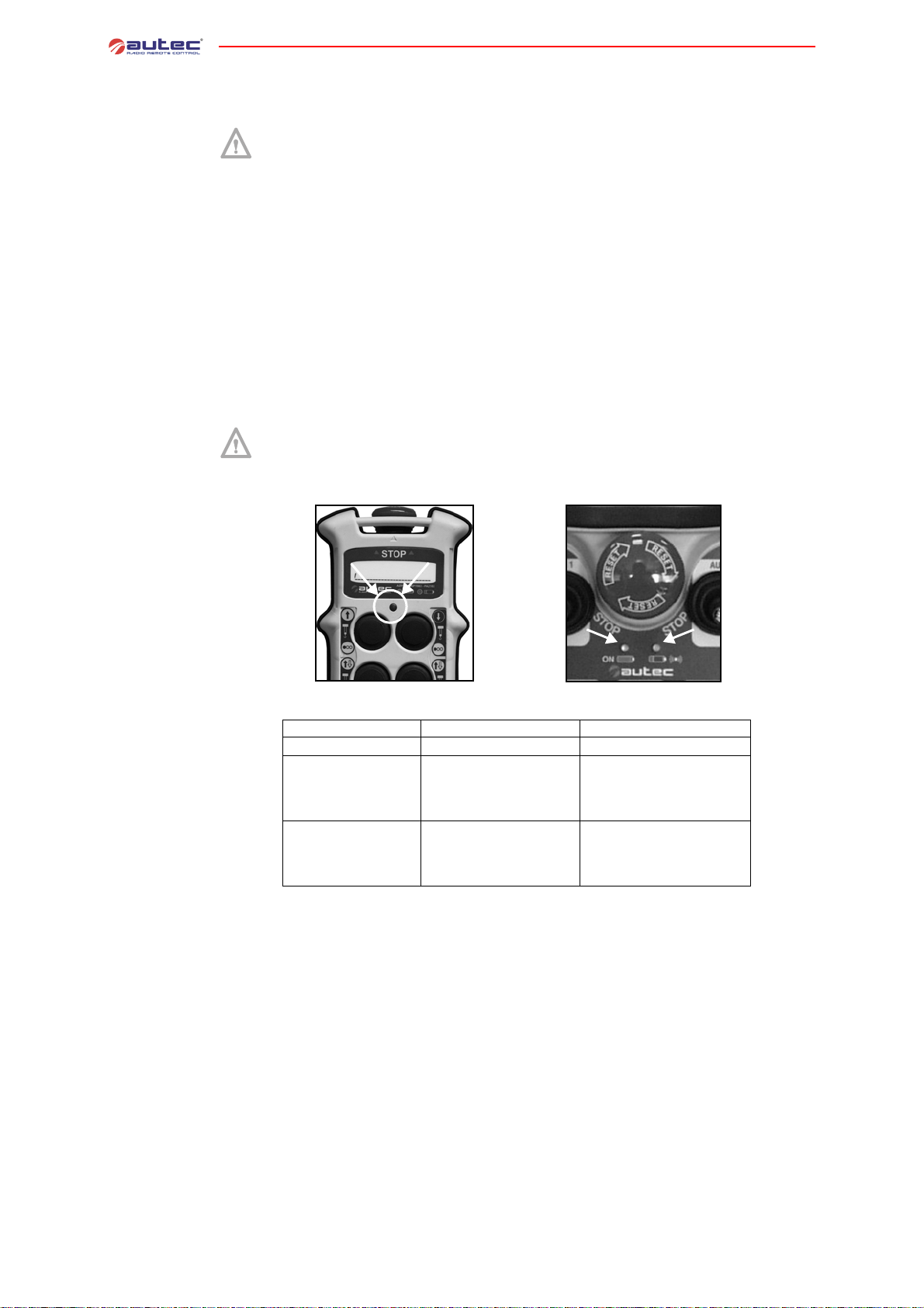
6 Operating mode of the transmitting units
6.2 STOP
The STOP pushbutton should be pressed when it is necessary to stop the machine
immediately when a dangerous condition should occur.
To stop the machine immediately, press the STOP pushbutton.
To start working again, after checking that the working conditions are safe, turn the STOP
pushbutton in the direction indicated to deactivate it and repeat the starting procedure.
The STOP circuit complies with category 3 according to the EN 954 - 1.
6.3 Battery
To recharge a low battery, proceed as follows:
1.Insert the battery into its proper battery charger, which should be positioned in an area with
a temperature between +5°C and +45°C: the battery now starts charging, a state signalled
by the lighting up of the “CHARGE” pilot light.
2.After a maximum of 3 hours the “CHARGE” light switches off: the battery is fully charged. Remove the battery from the charger (if the battery is not removed, the charger switches to
trickle charging).
Read and stick to the warnings given in the battery charger manual in order to
lengthen the life of the battery itself.
6.4 Signals
green LED blinks NORMAL OPERATION ///
red LED blinks, and
intermittent sound of
the buzzer
red LED with steady
light at starting, and
continuous sound of the
buzzer
6.5 Switching off
The transmitting unit should be switched off each time work is stopped by turning the starting
keyswitch to “O” position and extracting it (always put the k ey in a safe place).
The transmitting unit may also switch off automatically if the battery is not sufficiently charged
and/or when the radio remote control is not used for more than 3 and a half minutes (see
paragraph 8.1, DIP nr. 1 settings).
a
TYPE MEANING ACTION
LOW BATTERY: the transmitting unit switches off 3.5
minutes after the LED starts
blinking
ONE OR MORE (movement) ACTUATORS and/or
STOP PUSHBUTTON are
ACTIVATED
switch off the transmitting unit
and replace the battery
Disconnect all actuators and/
or the STOP pushbutton
b
- 22 -
LIMM&SA0-00.fm
Page 27
7 MAINTENANCE
These instructions do not in any case substitute the norms and laws that regulate work safety,
nor do they limit the responsibility of the purchaser and user of the radio remote control.
All control and maintenance actions carried out on the radio remote control must be verified and
recorded by the person in charge of carrying out maintenance on the machine.
Before carrying out maintenance, it is recommended to replace the battery with
a charged one and to ensure the efficiency of the starting keyswitch.
After each maintenance action, always make sure that commands sent by the
transmitting unit only activate the corresponding expected operations.
Routine maintenance carried out as described in this manual is fundamental for
using the radio remote control safely.
7.1 Routine maintenance
Routine maintenance consists of operations carried out to maintain (through verifications, restoration, programmed replacements) the use and working conditions foreseen by Autec when the product is placed on the market.
Special applications may need more specific routine maintenance actions to be carried out at
different periods.
All given instructions must be followed correctly each time the machine and the radio
remote control are put into service.
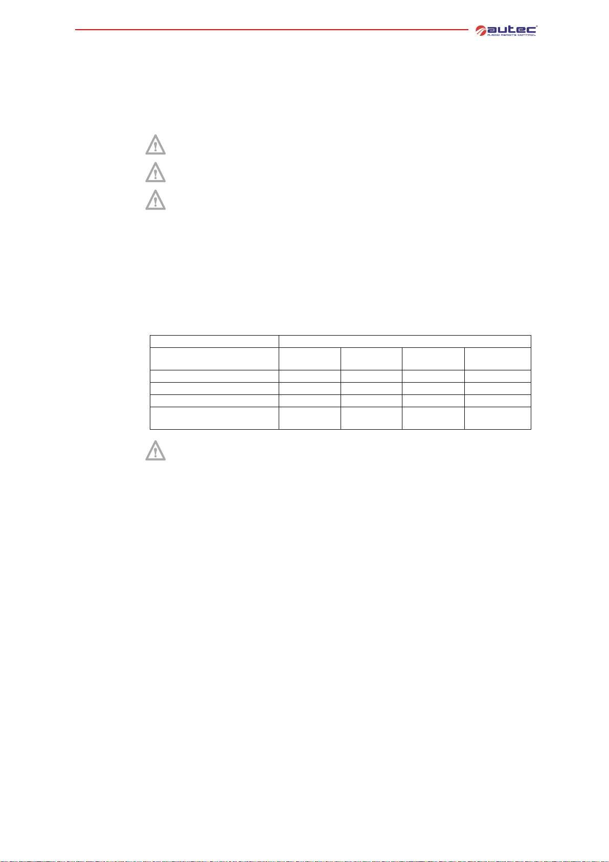
7 Maintenance
Transmitting
units
Receiving
units
Component
Daily
Transmitting units X
Receiving units X
Electrical operation X
External
electrical conductors
If problems are noted while carrying out routine maintenance, disable the system “machine+radio remote control” and follow the indications provided in
chapter 9.
Every day:
1.remove dust or accumulations of other material from the transmitting unit: never use solvents
or flammable/corrosive materials to clean, and do not use high pressure water cleaners or
steam cleaners
2.store the t ransmitting unit in clean and dry areas
3.make sure that the gaskets, bellows and caps of the joysticks, selectors and pushbuttons are
intact, soft and elastic
4.make sure that the battery housing and the battery contacts are always clean
5.check structural integrity of the transmitting unit
6.make sure that the panel symbols can be easily recognised and replace the panel if necessary
7.check that the identification plate is readable and not damaged
8.make sure that the STOP pushbutton works properly before using the radio remote control
9.check that the selector 1/1+2/2 works properly before starting to work.
Every 3 months:
1.remove dust or accumulations of other material from the receiving unit: never use solvents
or flammable/corrosive materials to clean, and do not use high pressure water cleaners or
steam cleaners
2.check structural integrity of the receiving unit
3.check that the internal wiring of the receiving unit is int act and connected
4.make sure that the panel symbols can be easily recognised and replace the panel if necessary
5.check that the identification plate is readable and not damaged
Every 3
months
Interval
Every 6
months
Every 12
months
X
Electrical
operation
LIMM&SA0-00.fm
Every six months:
1.make sure that all the relay contacts of the receiving unit operate correctly, and check that
the contact closes when the corresponding m anoeuvre is enabled and opens when the manoeuvre is disabled
2.check the correct correspondence between the commands that are sent and the manoeuv res
that are carried out
3.check that the contact for the SAFETY relay is open when no movement command has been
sent. This is safety critical maintenance. it is necessary to keep a record (date, signature ,
- 23 -
Page 28
comments) showing that this check has been regularly carried out. Keep the record together
with other installation documents.
External
electrical
conductors
7 Maintenance
7.2 Special maintenance
Every twelve months:
1.make sure that the cable which connects the receiving unit to the machine is intact along the
full length
2.make sure that the connecting plugs and sockets are intact and connected
3.check the strips or other fixing systems and replace them if necessary
4.make sure that the connecting cable is not damaged, particularly at the cable glands
Special maintenance consists of operations carried out in order to restore use and
working conditions foreseen when the product is placed on the market; this happens
through non-programmed replacement of damaged or worn out parts or components
with original parts or components.
Always ensure that the receiving unit has been disconnected from the power
source and that the battery has been removed from the transmitting unit before
carrying out any special maintenance work.
Any fault should be repaired by authorised personnel (contact Service), using
original Autec spare parts only.
The following radio remote control data must be communicated in order to make interventions
faster and more reliable:
- serial number
-purchase date (given on the certificate of guarantee)
- description of the prob lem found
- address and telephone number of the place where the device is being used (with the name of
the person to contact)
- local supplier.
It is recommended to read and understand all parts of this manual, and make sure that
all the instructions it contains have been followed correctly before contacting the Service Technicians.
7.3 Disposal
When disposing of a radio remote control, give it to the waste separate collecting services in the
user's country.
Please pay particular attention when recycli ng the batte ries, applying loc al rules . Do not throw
them away with domestic trash.
- 24 -
LIMM&SA0-00.fm
Page 29
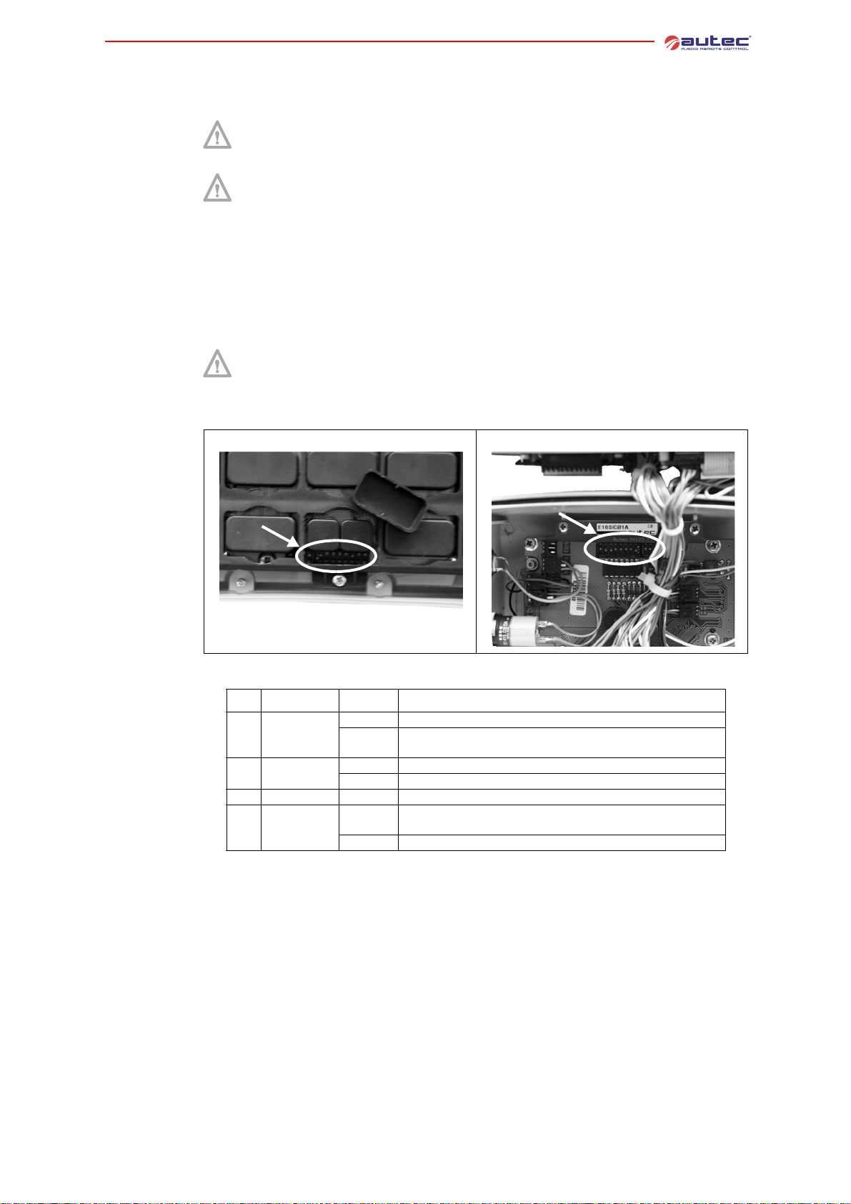
8PROGRAMMING
The dip switches can only be programmed by authorised personnel; programming is only possible when the receiving unit is not powered and the battery has
been removed from the transmitting unit.
The incorrect closure of the transmitting and the receiving unit can compromise
the seal between the casings and thereby the protection degree from dust and
water.
8.1 Programming the transmitting module
To change the programming set in the radio module, it is necessary to open the transmitting
unit.
The group of eight dip switches located on the radio modules is used to program some functions
and set the working frequency. The programming set in the other group of four dip switches
must never be modified.
For the correct functioning (see paragraph 1.7), the group of 8 dip switches (excluding DIP 1) for the radio modules E16STXEU_ and E16SRXEU_ must be set in
the same way.
Set the group of 8 dip switches as described below:
MK transmitting unit MJ transmitting unit
8 Programming
Group of
8 dip switches
DIP MODULE STATE FUNCTION
ON
The transmitting unit never switches off automatically
1E16STXEU_
a
E16STXEU_
2
3-7 E16STXEU_ ON/OFF
8E16STXEU_
a. With MK12 transmitting units this dip switch must be at ON.
Pay particular attention when closing the unit at the end of the operation.
If the transmitting unit stays switched on without any movement
OFF
commands activated, it switches off after approx. 3.5 minutes.
ON
Deactivation of low battery warning from horn on machine
OFF
Activation of low battery warning from horn on machine
See paragraph 1.7 and paragraph 8.5
Manual selection mode of the frequencies using DIP 3 - DIP 7
ON
(see paragraph 8.5)
OFF
DO NOT USE
LIMM&SA0-00.fm
- 25 -
Page 30
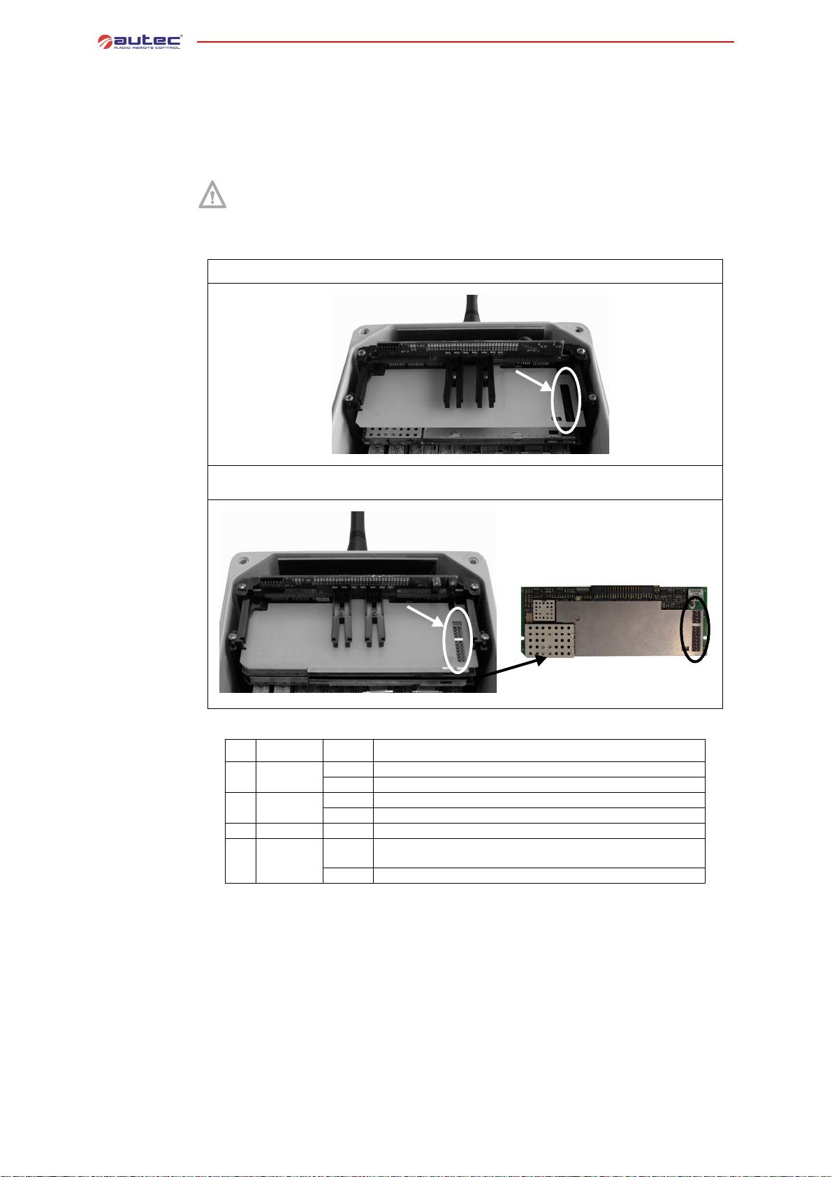
8.2 Programming the receiving module
To change the programming set in the radio module, it is necessary to open the receiv ing unit.
The group of eight dip switches located on the radio modules is used to program some functions
and set the working frequency. The programming set in the other group of four dip switches
must never be modified.
8 Programming
For the correct functioning (see paragraph 1.7), the group of 8 dip switches (excluding DIP 1) for the radio modules E16STXEU_ and E16SRXEU_ must be set in
the same way.
Set the group of 8 dip switches as described below:
Receiving unit URX-1 in the “Master/Slave” system
Radio module corresponding to the
transmitting unit UTX-M
Receiving unit URX-2 in the “Master/Slave” system
Receiving units URX-1 and URX-2 in the “Master/Master” system
Radio module corresponding
to the transmitting unit UTX-M
Radio module corresponding to the
transmitting unit UTX-S
Group of
8 dip switches
- 26 -
DIP MODULE STATE FUNCTION
ON
1 E16SRXEU_
a
E16SRXEU_
2
3-7 E16SRXEU_ ON/OFF
8 E16SRXEU_
a. With MK12 transmitting units this dip switch must be at ON.
Pay particular attention when closing the unit at the end of the operation.
Stop after 0.35 sec with invalid radio signal
OFF
Stop after 1 sec with invalid radio signal
ON
Deactivation of low battery warning from horn on machine
OFF
Activation of low battery warning from horn on machine
See paragraph 1.7 and paragraph 8.5
Manual selection mode of the frequencies using DIP 3 - DIP 7 (see
ON
paragraph 8.5)
OFF
DO NOT USE
LIMM&SA0-00.fm
Page 31
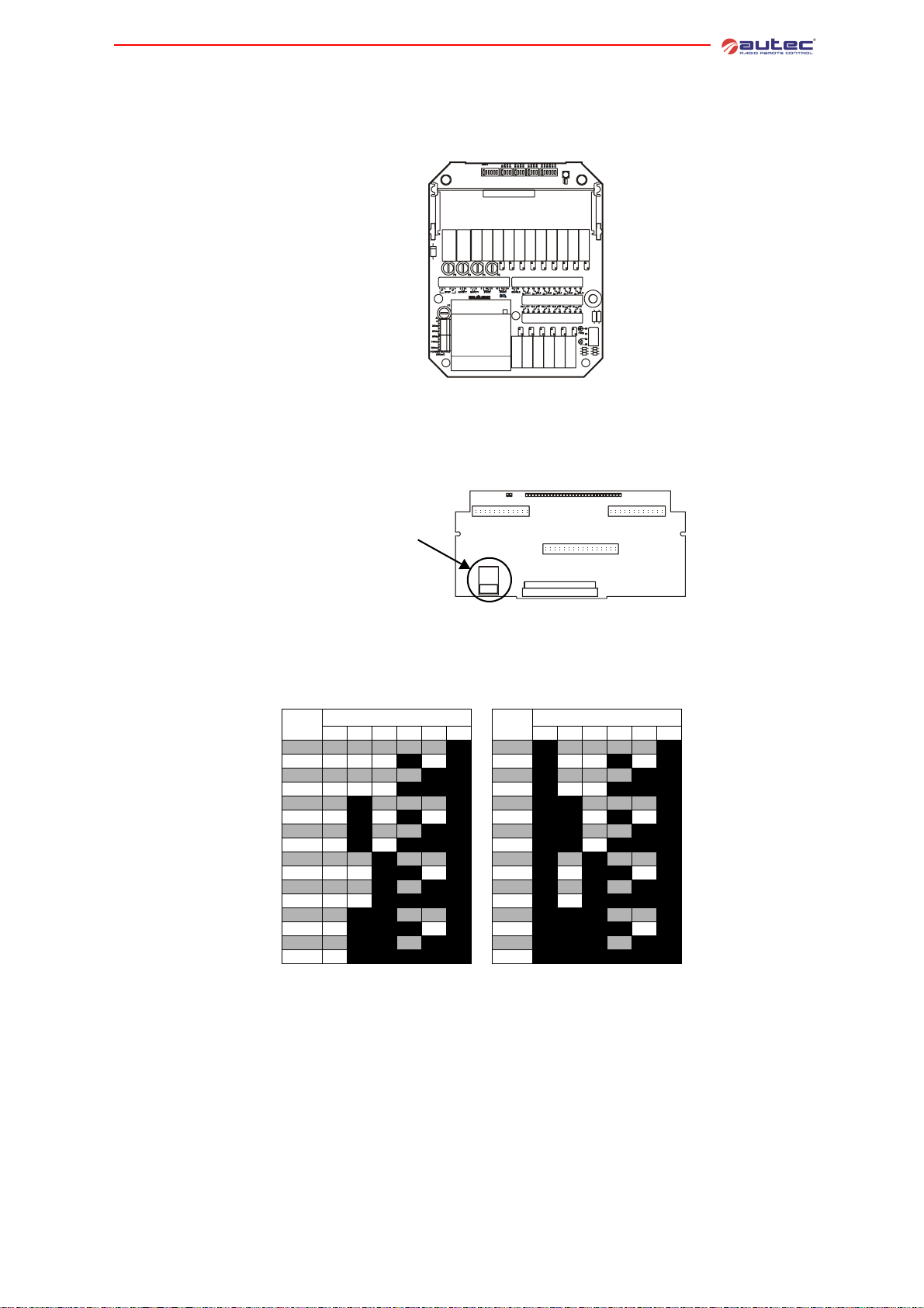
8.3 Programming the master board E16B14AC
Dip switch programming has to correspond to that given in the technical data sheet and must
not be modified.
8.4 Programming the bus board E16RI02_
Autec programs this bus board and programming is recorded in the data memory that configures
outputs of the receiving unit.
Data memory
8 Programming
8.5 Frequency tables
Settable
frequencies
MHz
902.150 OFF OFF OFF OFF OFF ON 915.350 ON OFF OFF OFF OFF ON
903.050 OFF OFF OFF ON OFF ON 916.250 ON OFF OFF ON OFF ON
903.850 OFF OFF OFF OFF ON ON 917.050 ON OFF OFF OFF ON ON
904.650 OFF OFF OFF ON ON ON 917.850 ON OFF OFF ON ON ON
905.525 OFF ON OFF OFF OFF ON 918.675 ON ON OFF OFF OFF ON
906.325 OFF ON OFF ON OFF ON 919.525 ON ON OFF ON OFF ON
907.175 OFF ON OFF OFF ON ON 920.375 ON ON OFF OFF ON ON
907.975 OFF ON OFF ON ON ON 921.175 ON ON OFF ON ON ON
908.850 OFF OFF ON OFF OFF ON 922.050 ON OFF ON OFF OFF ON
909.650 OFF OFF ON ON OFF ON 922.850 ON OFF ON ON OFF ON
910.450 OFF OFF ON OFF ON ON 923.650 ON OFF ON OFF ON ON
911.250 OFF OFF ON ON ON ON 924.450 ON OFF ON ON ON ON
912.125 OFF ON ON OFF OFF ON 925.325 ON ON ON OFF OFF ON
912.925 OFF ON ON ON OFF ON 926.175 ON ON ON ON OFF ON
913.775 OFF ON ON OFF ON ON 926.925 ON ON ON OFF ON ON
914.525 OFF ON ON ON ON ON 927.725 ON ON ON ON ON ON
E16STXUS1 and E16SRXUS1
DIP SWITCH
345678 345678
MHz
DIP SWITCH
LIMM&SA0-00.fm
- 27 -
Page 32
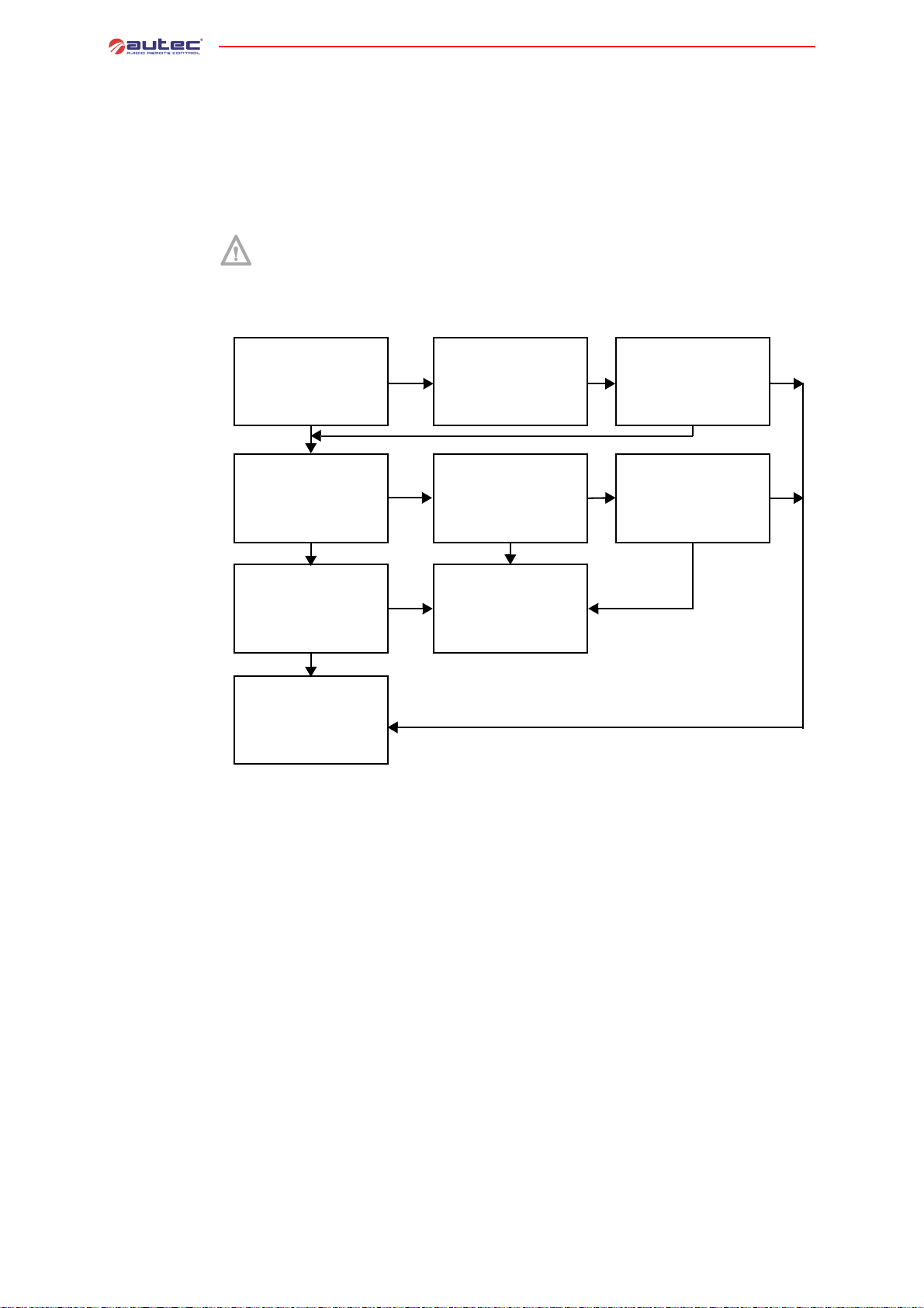
9 Diagnostics
9DIAGNOSTICS
If the system “machine+radio remote control” does not start, check if the problem is caused by
the radio remote control or the machine. Therefore, before carrying out any verification connect
the cable control unit: if the machine does not start, the problem lies with the machine itself.
If, on the other hand, the machine only s tarts when using the cable control unit, the problem
lies with the radio remote control. In this ca se, follow the diagnostic procedure related to the
transmitting unit and that related to the receiving unit if it is the case, and proceed as follows.
Before carrying out diagnostics it is recommended to replace the battery with a
charged one and ensure the efficiency of the starting keyswitch.
9.1 Transmitting unit diagnostics
When START is
activated, is the red LED
lit steadily and does the
buzzer sound?
NO
Does the red LED blink
and does the buzzer
sound?
NO
Does the green LED
blink?
NO
CALL TECHNICAL
ASSISTANCE
STOP pushbutton or one
YES
YES
YES
of the movement
actuators are activated:
disconnect it/them.
The battery is discharged:
replace it with a fully
charged one. Does the
LED continue to blink and
the buzzer sounding?
Carry out diagnostics
checks on the receiving
unit (see paragraph 9.2)
NO
Is the LED lit with a steady
light?
Clean contacts in the bat-
YES
tery housing. Does the
LED continue to blink and
the buzzer sounding?
YES
NO
YES
NO
- 28 -
LIMM&SA0-00.fm
Page 33
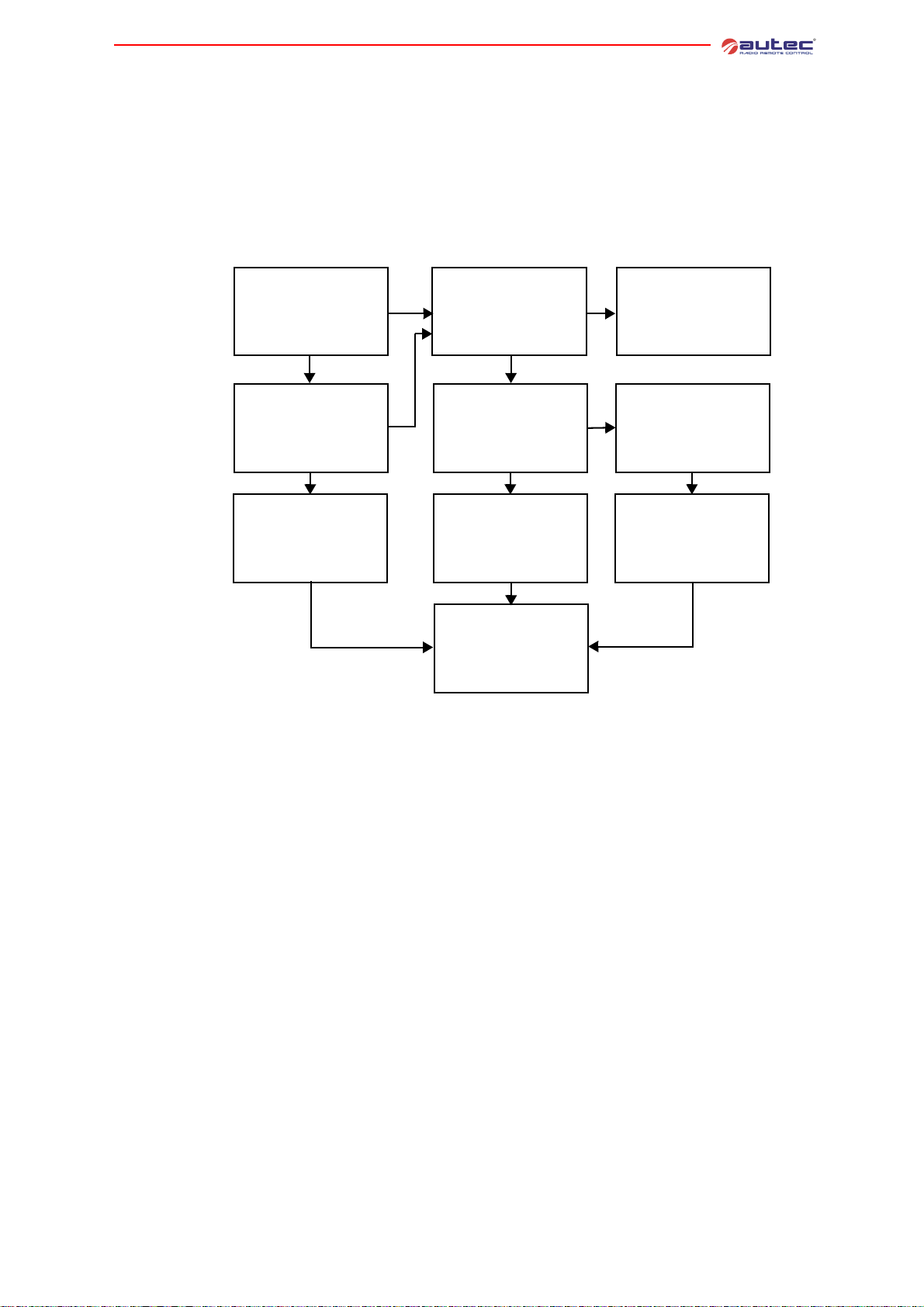
9.2 Receiving unit diagnostics
If diagnostics described in paragraph 9.1 has been carried out with the transmitting unit UTX-S
of a “Master/Slave” system, carry out the diagnostic procedure with the receiving unit URX-2.
If diagnostics described in paragraph 9.1 has been carried out with the transmitting unit UTX-M
of a “Master/Slave” system, carry out the diagnostic procedure twice, one with the receiving unit
URX-1 only, the other with the receiving unit URX-2 only.
If, on the contrary, diagnostics of paragraph 9.1 has been carried out with a tran smitting unit
of a “Master/Master” system, carry out diagnostic procedure twice , one with the recei ving unit
URX-1 only and another one with the receiving unit URX-2 only.
9 Diagnostics
Is the POWER ENABLE
signal light switched off?
NO
Is the POWER ENABLE
signal light blinking?
NO
Change the frequency set
in the radio modules (see
paragraph 1.7).
Does the machine start?
NO
(*) If the address keys (E16SCHEU_) have been replaced, do the following:
- check that the transmitting unit is off and the receiving unit is powered
- switch on the transmitting unit
- press the START pushbutton without releasing it for at least 5 seconds.
YES
YES
Is the connecting plug
between the radio remote
control and the machine
connected correctly?
YES
Remove power from the
receiving unit. Check fus-
es. Are they intact?
YES
If the address keys have
been changed it is necessary to reconfigure the re-
ceiving unit (*). Does the
machine start?
NO
CALL TECHNICAL
ASSISTANCE
NO
NO
Correctly insert
the connecting plug
and start the
radio remote control.
Check the power supply
connections.
Replace blown fuses.
Connect to power source
and switch on radio remote control. Does the
machine start?
NO
LIMM&SA0-00.fm
- 29 -
Page 34

9 Diagnostics
- 30 -
LIMM&SA0-00.fm
Page 35

Page 36

www.autecsafety.com
Autec s.r.l.
Via Pomaroli, 65 - 36030 Caldogno (VI) Italy
tel +39.0444.901000 - fax +39.0444.901011
 Loading...